1. Introduction
With the rapid development of microfluidic and microdroplet technologies, applications for microdroplets have been widely reported in recent years. From biology [
1,
2,
3,
4,
5] to chemistry [
6,
7,
8,
9] and medicine [
10,
11,
12,
13], microdroplets have been used for volume control, protection, and transportation of samples. Moreover, microdroplets have provided an environment for the uniform and functional synthesis of microcapsules in industrial fields such as textiles [
14,
15] and cosmetics [
16]. They have been also used as efficient optical elements for displays [
17,
18] and detectors [
19,
20,
21].
Polymeric microcapsules have advanced remarkably using microdroplet technologies. Highly uniform microcapsules have been formed in miniaturized devices, and the functionality of these microcapsules has expanded as a result of new developments in microcapsule synthesis [
22,
23,
24]. Formation of hollow microcapsules by direct injection of a gas into the capsule core is of particular interest [
25,
26,
27,
28,
29,
30,
31,
32,
33,
34]. Since the inner cavity and shell layer are formed directly in this technique, the number of materials available for capsule synthesis was significantly increased compared with single emulsion techniques using self-assembly or interfacial polymerization of the shell layer [
35,
36,
37].
Researchers in this field have typically formed gas cores and shell layers in a T-shaped channel, cross channel, or glass capillary tube. Stone’s group used a combination of cross channels and T-shaped channels [
25,
26,
27]. In this work, core size and shell thickness were independently controlled. However, it was essential to match the generation rate and pitch of the droplets and the method often produced relatively thick shells. In contrast, Luo
et al. [
28,
29,
30] and Lee
et al. [
31,
32,
33] reported droplet formation methods using three-dimensional glass capillaries. They used a separated serial or simultaneous droplet generation structure to form core and shell layers. However, the fabrication of these glass capillary devices with proper nozzle dimensions also seemed difficult.
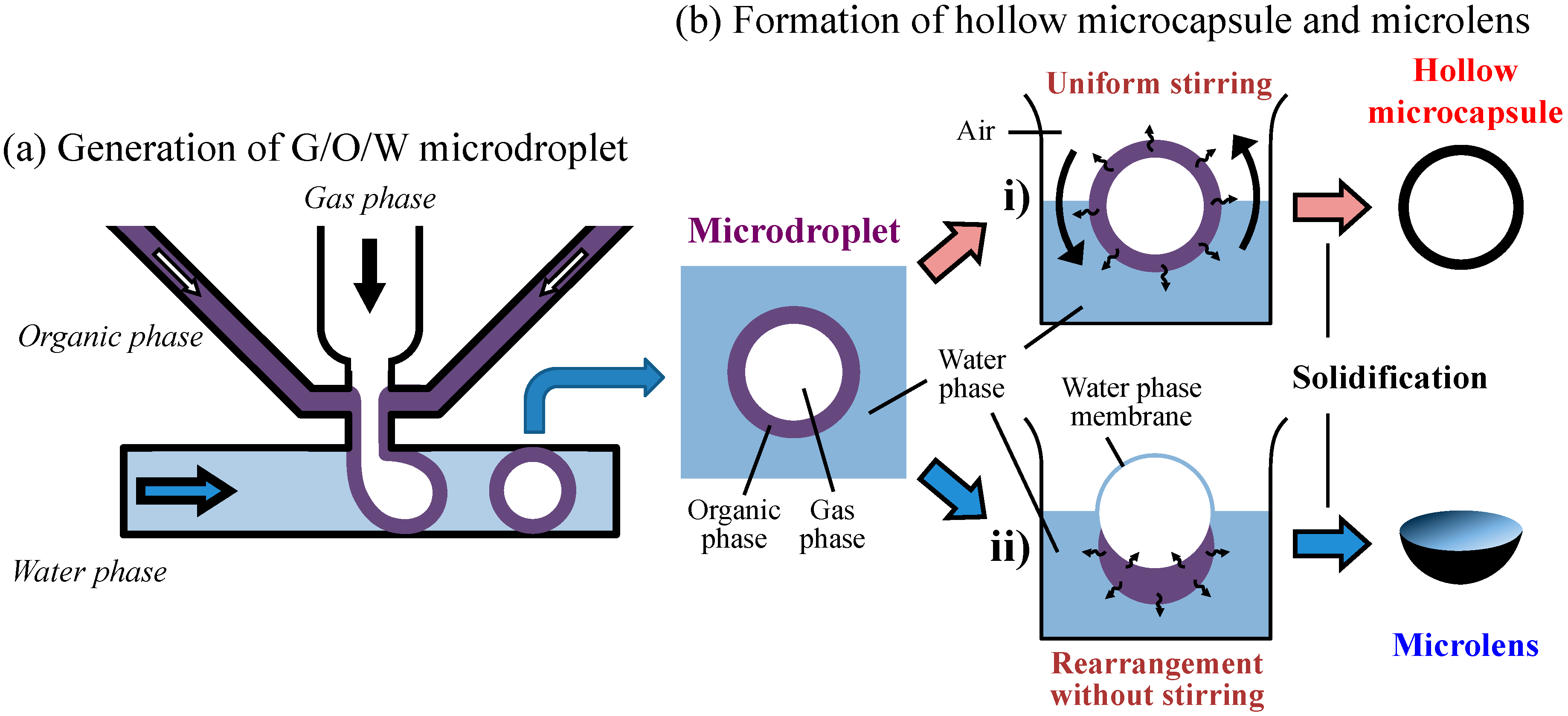
In contrast to these methods, we have proposed, in a previous work, a method for generating gas-in-organic-in-water (G/O/W) multiphase droplets on a single-junction silicon device [
38]. Gas cores and thin shell membranes were formed with high yield via this simple process. No complicated, difficult fabrication processes were involved to achieve efficient fluidic operation and a reproducible fluidic structure. Using this structure, we developed hollow microcapsules and microlenses from core-shell microdroplets.
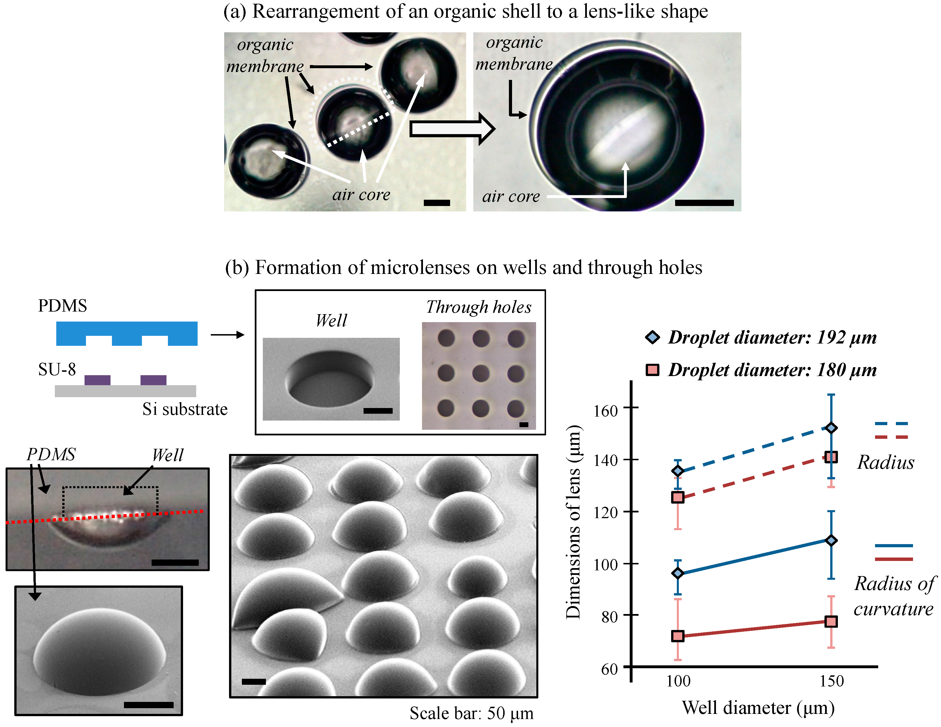
The gas core and organic shell droplets can be changed into a Janus droplet [
39,
40] according to its environmental condition such as stirring, thus our process has the flexibility of altering the positioning and arrangement of the droplets by varying synthesis conditions. In our method, the density of the gas core and the organic shell materials differed greatly. Therefore, when we varied the stirring and solidification conditions for the G/O/W droplets, organic shell layers were transformed into either a hollow capsule or a bowl-like or lens-like shape [
41]. Lens-shaped structures can be potentially used in optical element production. Since the volume of gas core and the properties of the organic shell dictate the lens shape, optical properties of these lenses can be controlled by varying the fluidic conditions. Based on this new technology, we developed a prototype on-demand microlens production system in wells and through-holes on wells and through-holes.
Hence, the polymeric materials and formation methods derived from our gas core and polymeric shell droplet technology can be useful for various applications in materials science and chemistry.
3. Device Design and Fabrication
The device used for microdroplet generation consisted of a multiphase junction, an observation area, three inlets, one outlet, and various microchannels, as shown in
Figure 2. The three inlets were designed to channel the gas, organic phase and water, respectively, onto a single junction. Microdroplets generated were observed within a cylindrical area 1 mm in diameter (the size of the droplets was larger than the width of the water phase channel).
A two-step photoresist pattering and silicon etching process formed the fluidic channels. The three inlets and one outlet were formed by etching the backside of a 200 μm thick silicon wafer to a depth of 100 μm using a deep reactive ion etching (DRIE) process. A second DRIE process was then applied to the front side of the silicon wafer. This second etching step produced the multiphase junction, observation area, and channels. The etching depth on the front side was also 100 μm. This procedure formed all of the channels for microdroplet generation and the through-holes for inlets and outlets, and also protected the fragile, fine patterns from contamination and mechanical damage during the second DRIE and cleaning process. Then we anodically bonded the front side of the newly pattered silicon wafer to glass (TEMPAX Float, Schott, Mainz, Germany) for visualization and fluidic sealing. Finally, we bonded copper ports to the backside for connection of the inlet and outlet tubes for use in our fluidic experiments.
Figure 2.
Silicon wafer design for microdroplet generation and, in the inset, detail of the multiphase junction.
Figure 2.
Silicon wafer design for microdroplet generation and, in the inset, detail of the multiphase junction.
4. Results and Discussion
Fluids used to form the G/O/W droplet were as follows: The gas phase was air, the organic phase was a solution of 5 wt % polystyrene (MW: 250000) in dichloromethane, and the water phase was a solution of 3 wt % polyvinyl alcohol (PVA) in deionized water. Polystyrene was selected because it is a widely available plastic with excellent manufacturability and hardness. Dichloromethane was selected because it is a good polystyrene solvent that has solubility in water and a high rate of evaporation in air. Furthermore, we used the PVA solution as a dispersion agent solution to prevent the generated droplets from merging with one another.
A syringe (1750CX, Hamilton, Reno, NV, USA) and syringe pump (KDS210, KD Scientific, Holliston, MA, USA) were used to inject the water and organic phases into the channels. A pressure regulator (2657 pneumatic pressure standard, Yokogawa, Tokyo, Japan) controlled the gas phase pressure. A high-speed camera (FASTCAM-NEO, Photron, Tokyo, Japan) monitored the continuous generation of droplets. Droplet size was measured by pixel analysis of the captured images.
4.1. Generation of G/O/W Microdroplets
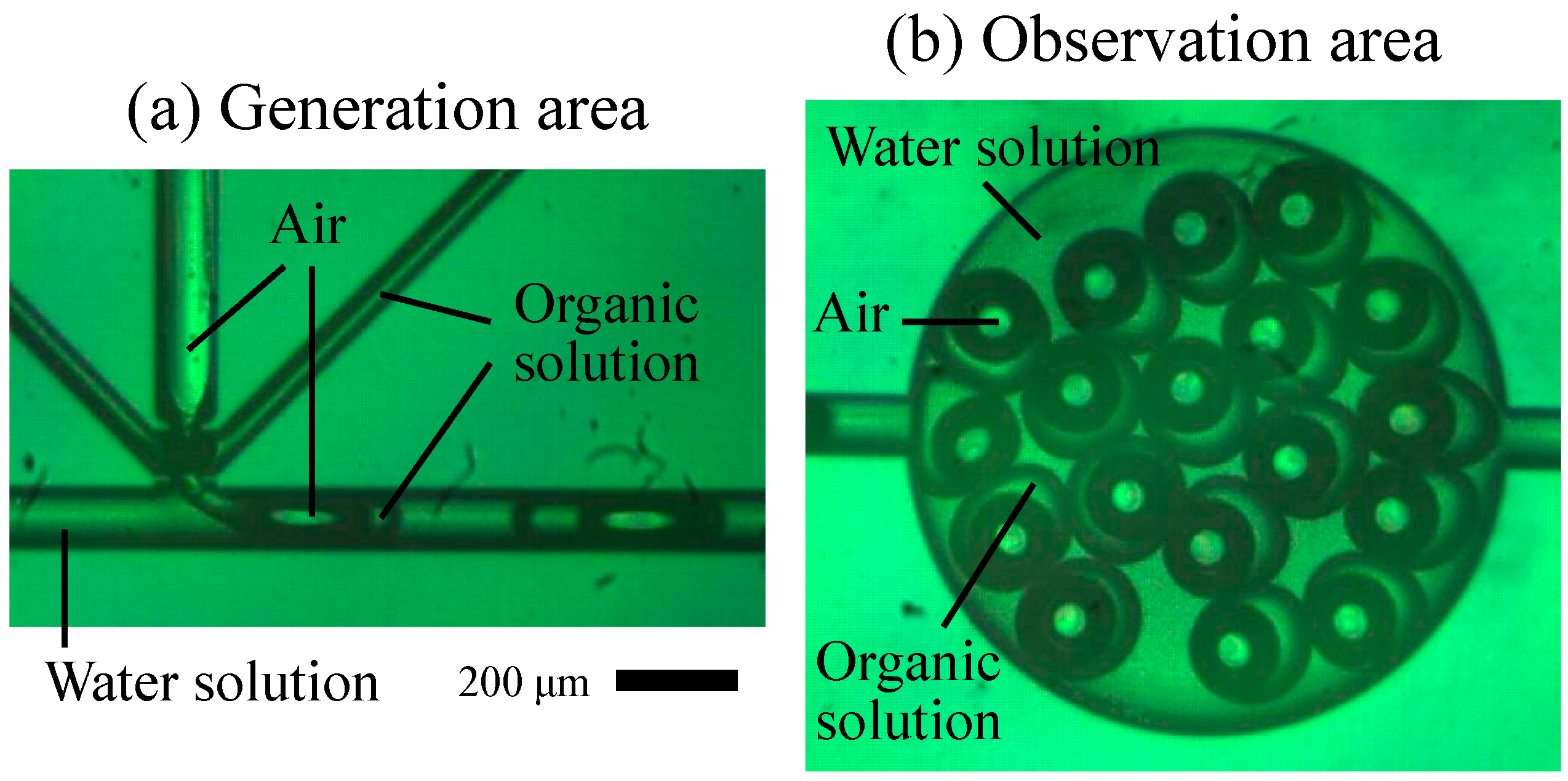
As shown in
Figure 3, microdroplets were successfully generated at a multiphase junction. Gas was directly injected into the organic membrane via the vertical channel, and then the gas and fluid phases were inflated which formed the G/O/W droplets.
The flow rates of each of the three phase fluids determined the gas core size and the organic membrane thickness of the droplets.
Figure 4 shows the dimensions of the G/O/W droplets
versus the flow rates of each fluid phase. Gas core size increased linearly with an increase in gas pressure, as shown in
Figure 4a. Gas core size decreased linearly with an increase in the organic phase flow rate, as shown in
Figure 4b. The size of whole droplets did not change dramatically relative to the size of the gas core when the gas pressure and organic phase flow rates were changed. We expected that, under a fixed water phase flow rate, droplet size would increase when the sample flow rate in the common T-junction increased, but this did not occur. The droplet consisting of organic and gas phases showed different results with W/O and O/W droplet generation. We believe this is because the gas and organic solution have different physical properties, surface tensions and viscosities. Consequently, the two fluids’ different properties and hydrodynamic shear force in the T-junction resulted in the different droplet sizes, hence, the minimum size of the generated droplets shifted up and down based upon the specific conditions of these two phases.
Figure 3.
Images of G/O/W microdroplets in (a) the generation area within the multiphase junction and (b) the observation area.
Figure 3.
Images of G/O/W microdroplets in (a) the generation area within the multiphase junction and (b) the observation area.
Figure 4.
Results of the multiphase droplet generation that occurred by controlling the flow rate of each phase fluid. (a) Droplet and core diameters vs. gas pressure; (b) droplet dimensions vs. organic phase flow; (c) droplet dimensions vs. water phase flow.
Figure 4.
Results of the multiphase droplet generation that occurred by controlling the flow rate of each phase fluid. (a) Droplet and core diameters vs. gas pressure; (b) droplet dimensions vs. organic phase flow; (c) droplet dimensions vs. water phase flow.
In contrast, the droplet and gas core size decreased simultaneously when the water phase flow rate increased, as shown in
Figure 4c. Furthermore, the droplet and core size changed when the organic flow rate and gas pressure was changed.
In conclusion, we demonstrated the systematic and independent control of droplet size, gas core size, and organic membrane thickness of microcapsules by varying the flow conditions of each fluid phase. We generated diameters of the droplet and gas core diameters ranging from 184–147 μm, and 159–95 μm, respectively.
4.4. Discussion
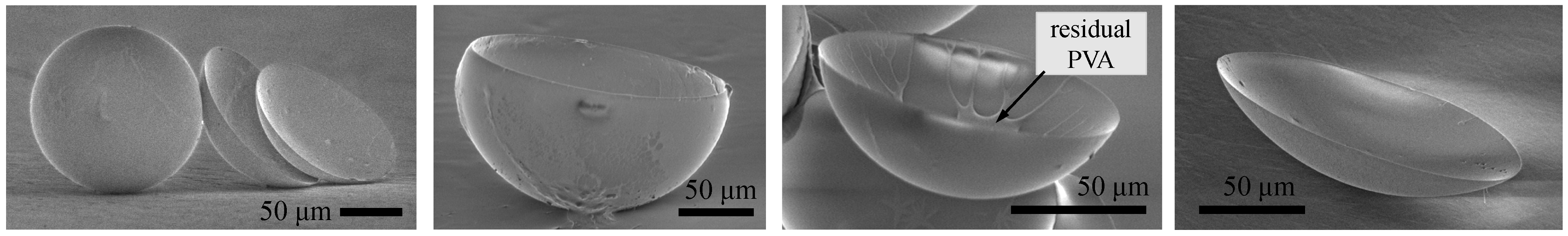
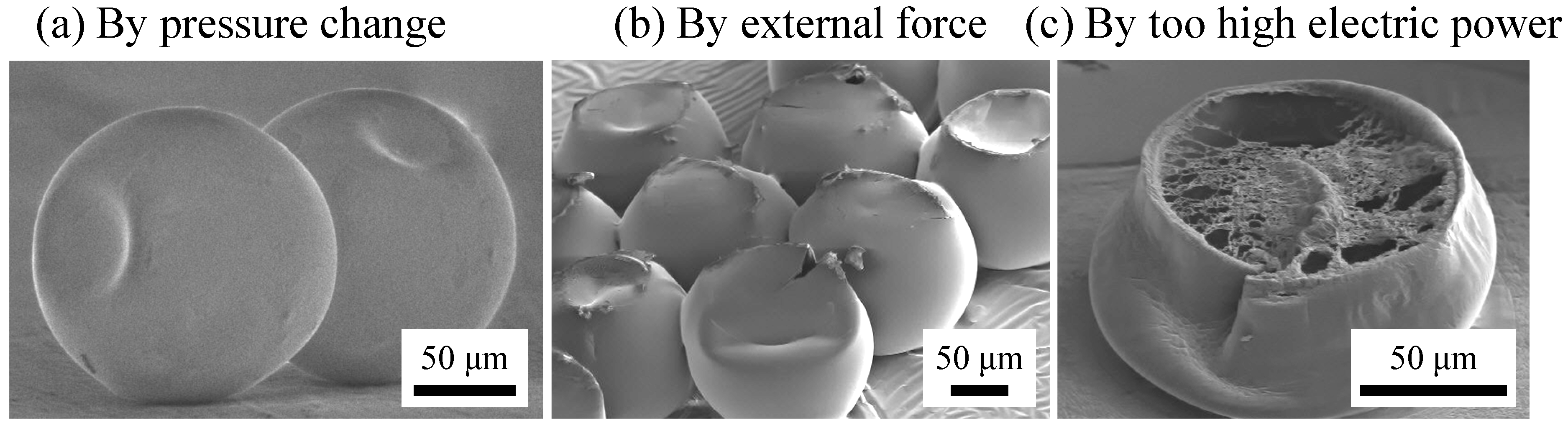
Compared to liquid droplet generation, the solidification process for microcapsule and microlens formation required particular conditions. Our work showed that capsule and lens formation and the shape of the solidified polymer were strongly dependent upon release conditions of organic solvent. We also demonstrated that the environmental conditions of the microcapsule/microlens system during its formation affected the gas core volume and the shell membrane thickness. Change in temperature also caused partial deformation of sphere capsules.
In addition, we determined that the efficiency of lens formation using a through-hole array was higher than using a well array. When we used a well array, the lens-like polymer layer frequently fell of the PDMS structure because this structure did not allow gas in the core to escape and large volumes disrupted contact of this structure with the polymer. Even using the through-hole structure, however, careful handling was required to assure microdroplets actually form microlenses.
5. Conclusions
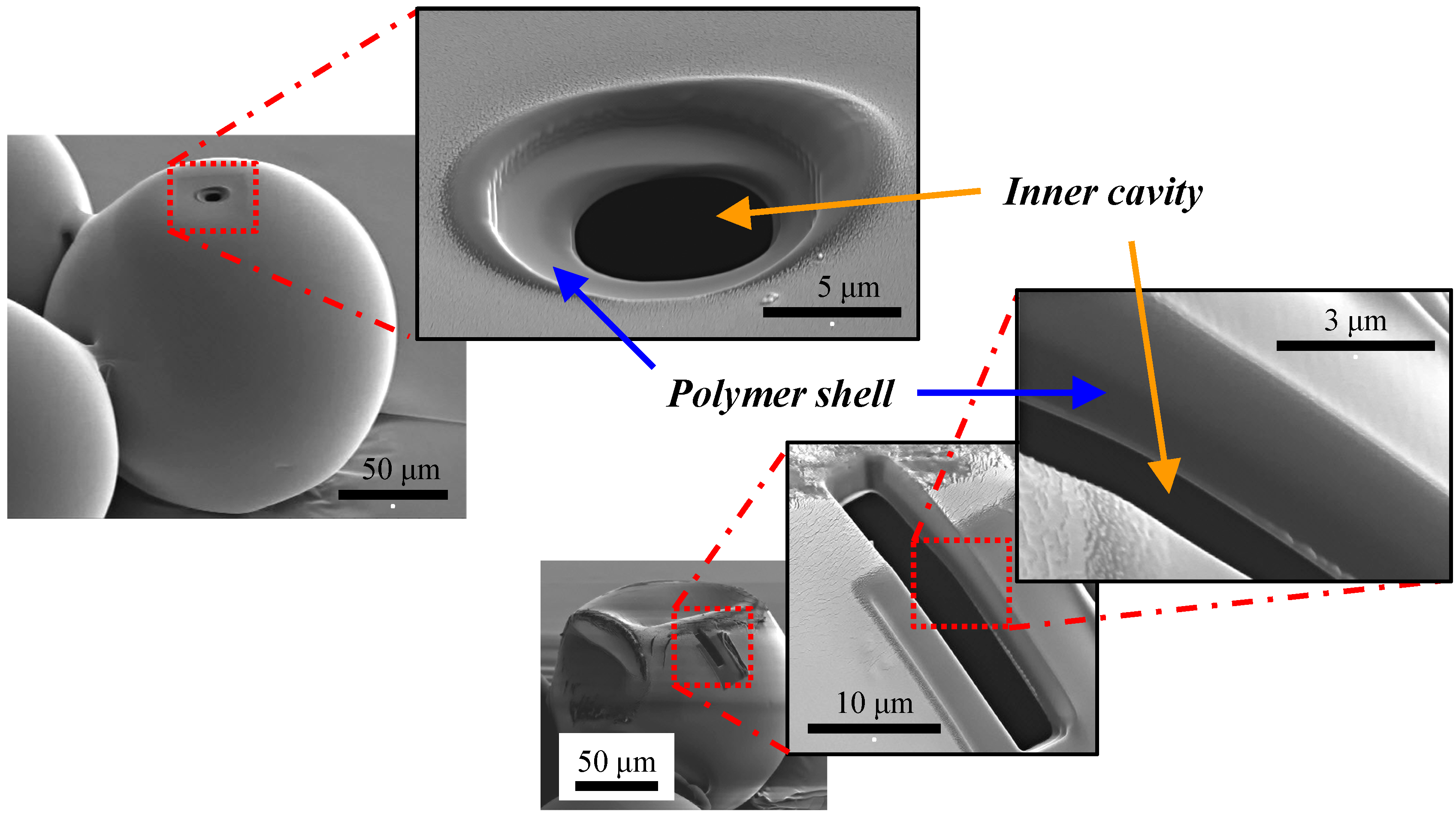
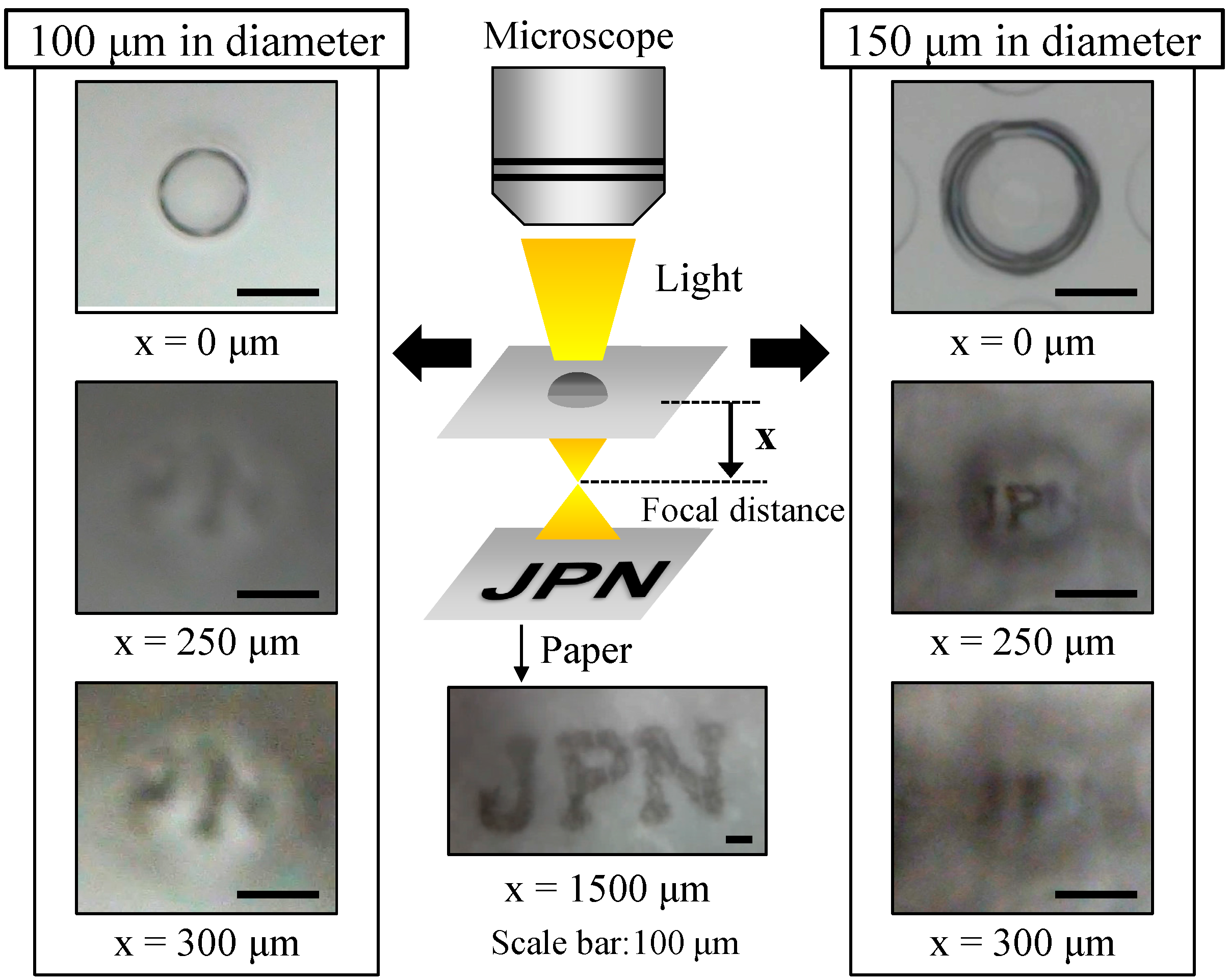
The polymeric hollow microcapsules and microlenses were successfully formed using gas-in-organic-in-water microdroplets. We controlled the size of the microdroplets and gas core by adjusting the flow rates of the gas, organic, and water phases. We could form microdroplets in hollow microcapsules or microlenses depending upon the solidification conditions employed. Hollow microcapsules formed when we used uniform stirring conditions. A non-porous polymer shell was formed with a membrane thickness of 2% of the capsule diameter, which effectively sealed the gas core for long periods of time. Furthermore, microlenses were formed from the core and shell materials that had greatly different densities. Under some conditions, microlenses formed on both well and through-hole structures. We could adjust the size and optical properties of the microlenses by adjusting the size of the PDMS structures.
The multiphase microdroplets were formed by a simply modified T-junction structure without surface treatment. This work provided practical applications of the multiphase microdroplets and potential availabilities to a variety of materials and synthesis methods. We believe our microcapsule device and synthesis methods will have a wide range of application in chemistry and biology. In addition, we believe our lens formation methods using multiphase droplets will have applications in the formation of in-channel and on-demand optical components.
Acknowledgments
This work is partly supported by Japan Ministry of Education, Culture, Sports Science & Technology (MEXT) Grant-in-Aid for Scientific Basic Research (S) No. 23226010. And the authors thank for MEXT Nanotechnology Platform Support Project of Waseda University.
Author Contributions
Dong Hyun Yoon, Takahiro Arakawa and Shuichi Shoji conceived and designed the device and experiments; Dong Hyun Yoon and Kenta Hasegawa fabricated devices and performed the experiments; Yuji Kaneko partially fabricated the device; Dong Hyun Yoon, Jeung Sang Go, Tetsushi Sekiguchi and Shuichi Shoji contributed materials and analysis; Dong Hyun Yoon wrote the paper.
Conflicts of Interest
The authors declare no conflict of interest.
References
- Lim, F.; Sun, A.M. Microencapsulated islets as bioartificial endocrine pancreas. Science 1980, 210, 908–910. [Google Scholar] [CrossRef] [PubMed]
- Chia, S.M.; Wan, A.C.; Quek, C.H.; Mao, H.Q.; Xu, X.; Shen, L.; Ng, M.L.; Leong, K.W.; Yu, H. Multi-layered microcapsules for cell encapsulation. Biomaterials 2002, 23, 849–856. [Google Scholar] [CrossRef] [PubMed]
- Hosokawa, M.; Hoshino, Y.; Nishikawa, Y.; Hirose, T.; Yoon, D.H.; Mori, T.; Sekiguchi, T.; Shoji, S.; Takeyama, H. Droplet-based microfluidics for high-throughput screening of a metagenomic library for isolation of microbial enzymes. Biosensors Bioelectron. 2015, 67, 379–385. [Google Scholar] [CrossRef]
- Orive, G.; Castro, M.D.; Kong, H.J.; Hemandez, R.M.; Ponce, S.; Mooney, D.J.; Pedraz, J.L. Bioactive cell-hydrogel microcapsules for cell-based drug delivery. J. Control. Release 2009, 135, 203–210. [Google Scholar] [CrossRef] [PubMed]
- Ricci, M.; Blasi, P.; Giovagnoli, S.; Rossi, C.; Macchiarulo, G.; Luca, G.; Basta, G.; Calafiore, R. Ketoprofen controlled release from composite microcapsules for cell encapsulation: Effect on post-transplant acute inflammation. J. Control. Release 2005, 107, 395–407. [Google Scholar] [CrossRef] [PubMed]
- Song, H.; Chen, D.L.; Ismagilov, R.F. Reactions in droplets in microfluidic channels. Angew. Chem. Int. Ed. 2006, 45, 7336–7356. [Google Scholar] [CrossRef]
- Yoon, D.H.; Jamshaid, A.; Ito, J.; Nakahara, A.; Tanaka, D.; Akitsu, T.; Sekiguchi, T.; Shoji, S. Active microdroplet merging by hydrodynamic flow control using a pneumatic actuator-assisted pillar structure. Lab Chip 2014, 14, 3050–3055. [Google Scholar] [CrossRef] [PubMed]
- Fukuda, T.; Funaki, N.; Kurabayashi, T.; Suzuki, M.; Yoon, D.H.; Nakahara, A.; Sekiguchi, T.; Shoji, S. Real-time monitoring of chemical reaction in microdroplet using fluorescence spectroscopy. Sens. Actuators B Chem. 2014, 203, 536–542. [Google Scholar] [CrossRef]
- Mazutis, L.; Griffiths, A.D. Selective droplet coalescence using microfluidic systems. Lab Chip 2012, 12, 1800–1806. [Google Scholar] [CrossRef] [PubMed]
- Langer, R. New methods of drug delivery. Science 1990, 249, 1527–1533. [Google Scholar] [CrossRef] [PubMed]
- Zhao, Q.; Li, B. pH-controlled drug loading and release from biodegradable microcapsules. Nanomed. Nanotechnol. Biol. Med. 2008, 4, 302–310. [Google Scholar] [CrossRef]
- Pariot, N.; Levy, F.E.; Andry, M.C.; Levy, M.C. Cross-linked β-cyclodextrin microcapsules. II. Retarding effect on drug release through semi-permeable membranes. Int. J. Pharm. 2002, 232, 175–181. [Google Scholar] [CrossRef] [PubMed]
- Kooiman, K.; Bohmer, M.R.; Emmer, M.; Vos, H.J.; Chlon, C.; Shi, W.T.; Hall, C.S.; de Winter, S.H.P.M.; Schroen, K.; Versluis, M. Oil-filled polymer microcapsules for ultrasound-mediated delivery of lipophilic drugs. J. Control. Release 2009, 133, 109–118. [Google Scholar] [CrossRef] [PubMed]
- Nelson, G. Application of microencapsulation in textiles. Int. J. Pharm. 2002, 242, 55–62. [Google Scholar] [CrossRef] [PubMed]
- Giraud, S.; Bourbigot, S.; Rochery, M.; Vroman, I.; Tighzert, L.; Delobel, R.; Poutch, F. Flame retarded polyurea with microencapsulated ammonium phosphate for textile coating. Polym. Degrad. Stab. 2005, 88, 106–113. [Google Scholar] [CrossRef]
- Miyazawa, K.; Yajima, I.; Kaneda, I.; Yanaki, T. Preparation of a new soft capsule for cosmetics. J. Cosmet. Sci. 2000, 51, 239–252. [Google Scholar]
- Comiskey, B.; Albert, J.D.; Yoshizawa, H.; Jacobson, J. An electrophoretic ink for all-printed reflective electronic displays. Nature 1998, 394, 253–255. [Google Scholar] [CrossRef]
- Song, J.K.; Choi, H.J.; Chin, I. Preparation and properties of electrophoretic microcapsules for electronic paper. J. Microencapsul. 2007, 24, 11–19. [Google Scholar] [CrossRef] [PubMed]
- Ren, H.; Xu, S.; Wu, S.T. Deformable liquid droplets for optical beam control. Opt. Express 2010, 18, 11904–11910. [Google Scholar] [CrossRef] [PubMed]
- Yang, Y.; Ward, J.; Chormaic, S.N. Quasi-droplet microbubbles for high resolution sensing applications. Opt. Express 2014, 22, 6881–6898. [Google Scholar] [CrossRef] [PubMed]
- Smolyaninova, V.N.; Smolyaninov, I.I.; Kildishev, A.V.; Shalaev, V.M. Maxwell fish-eye eaton lenses emulated by microdroplets. Opt. Lett. 2010, 35, 3396–3398. [Google Scholar] [CrossRef] [PubMed]
- Bauer, W.C.; Fischlechner, M.; Abell, C.; Huck, W.T.S. Hydrophilic PDMS microchannels for high-throughput formation of oil-in-water microdroplets and water-in-oil-in-water double emulsions. Lab Chip 2010, 10, 1814–1819. [Google Scholar] [CrossRef] [PubMed]
- Abraham, S.; Jeong, E.H.; Arakawa, T.; Shoji, S.; Kim, K.C.; Kim, I.; Go, J.S. Microfluidics assisted synthesis of well-defined spherical polymeric microcapsules and their utilization as potential encapsulants. Lab Chip 2006, 6, 752–756. [Google Scholar] [CrossRef] [PubMed]
- Wan, J. Microfluidic-based synthesis of hydrogel particles for cell microencapsulation and cell-based drug delivery. Polymers 2012, 4, 1084–1108. [Google Scholar] [CrossRef]
- Wan, J.; Stone, H.A. Microfluidic generation of a high volume fraction of bubbles in droplets. Soft Matter 2010, 6, 4677–4680. [Google Scholar] [CrossRef]
- Wan, J.; Stone, H.A. Coated gas bubbles for the continuous synthesis of hollow inorganic particles. Langmuir 2012, 28, 37–41. [Google Scholar] [CrossRef] [PubMed]
- Wan, J.; Bick, A.; Sullivan, M.; Stone, H.A. Controllable microfluidic production of microbubbles in water-in-oil emulsions and the formation of porous microparticles. Adv. Mater. 2008, 20, 3314–3318. [Google Scholar] [CrossRef]
- Wang, W.T.; Chen, R.; Xu, H.H.; Wang, Y.D.; Luo, G.S. One-step microfluidic approach for controllable production of gas-in-water-in-oil (G/W/O) double emulsions and hollow hydrogel microspheres. RSC Adv. 2014, 4, 16444–16448. [Google Scholar] [CrossRef]
- Xu, J.H.; Chen, R.; Wang, Y.D.; Luo, G.S. Controllable gas/liquid/liquid double emulsions in a dual-coaxial microfluidic device. Lab Chip 2012, 12, 2029–2036. [Google Scholar] [CrossRef] [PubMed]
- Chen, R.; Dong, P.F.; Xu, J.H.; Wang, Y.D.; Luo, G.S. Controllable microfluidic production of gas-in-oil-in-water emulsions for hollow microspheres with thin polymer shells. Lab Chip 2012, 12, 3858–3860. [Google Scholar] [CrossRef] [PubMed]
- Lee, M.H.; Lee, D. Elastic instability of polymer-shelled bubbles formed from air-in-oil-in-water compound bubbles. Soft Matter 2010, 6, 4326–4330. [Google Scholar] [CrossRef]
- Lee, M.H.; Prasad, V.; Lee, D. Microfluidic fabrication of stable nanoparticle-shelled bubbles. Langmuir 2010, 26, 2227–2230. [Google Scholar] [CrossRef] [PubMed]
- Brugarolas, T.; Park, B.J.; Lee, M.H.; Lee, D. Generation of amphiphilic Janus bubbles and their behavior at an air-water interface. Adv. Funct. Mater. 2011, 21, 3924–3931. [Google Scholar] [CrossRef]
- Hettiarachchi, K.; Lee, A.P. Polymer-lipid microbubbles for biosensing and the formation of porous structures. J. Colloid Interface Sci. 2010, 344, 521–527. [Google Scholar] [CrossRef] [PubMed]
- Gao, F.; Su, Z.G.; Wang, P.; Ma, G.H. Double emulsion templated microcapsules with single hollow cavities and thickness-controllable shells. Langmuir 2009, 25, 3832–3838. [Google Scholar] [CrossRef] [PubMed]
- Cheng, C.J.; Chu, L.Y.; Ren, P.W.; Zhang, J.; Hu, L. Preparation of monodisperse thermo-sensitive poly(N-isopropylacrylamide) hollow microcapsules. J. Colloid Interface Sci. 2007, 313, 383–388. [Google Scholar] [CrossRef] [PubMed]
- Gao, Q.; Wang, C.; Liu, H.; Wang, C.; Liu, X.; Tong, Z. Suspension polymerization based on inverse pickering emulsion droplets for thermo-sensitive hybrid microcapsules with tunable supracolloidal structures. Polymer 2009, 50, 2587–2594. [Google Scholar] [CrossRef]
- Arakawa, T.; Yamamoto, T.; Shoji, S. Micro-bubble formation with organic membrane in a multiphase microfluidic system. Sens. Actuators A Phys. 2008, 143, 58–63. [Google Scholar] [CrossRef]
- Yang, S.; Guo, F.; Kiraly, B.; Mao, X.; Lu, M.; Leong, K.W.; Huang, T.J. Microfluidic synthesis of multifunctional Janus particles for biomedical applications. Lab Chip 2012, 12, 2097–2102. [Google Scholar] [CrossRef] [PubMed]
- Lone, S.; Cheong, I.W. Fabrication of polymeric Janus particles by droplet microfluidics. RSC Adv. 2014, 4, 13322–13333. [Google Scholar] [CrossRef]
- Xu, K.; Xu, J.H.; Lu, Y.C.; Luo, G.S. A novel method of fabricating, adjusting, and optimizing polystyrene colloidal crystal nonspherical microparticles from gas-water Janus droplets in a double coaxial microfluidic device. Cryst. Growth Des. 2014, 14, 401–405. [Google Scholar] [CrossRef]
© 2015 by the authors; licensee MDPI, Basel, Switzerland. This article is an open access article distributed under the terms and conditions of the Creative Commons Attribution license (http://creativecommons.org/licenses/by/4.0/).


 ,
, 