Article

Nano-Workbench: A Combined Hollow AFM Cantilever and Robotic Manipulator †

by
Héctor Hugo Pérez Garza
1,‡,
Murali Krishna Ghatkesar
1,*,‡,
Shibabrata Basak
2,
Per Löthman
3 and
Urs Staufer
1
1
Precision and Microsystems Engineering, Delft University of Technology, Mekelweg 2, 2628 CD Delft, The Netherlands
2
National Centre for HREM, Kavli Institute of Nanoscience Delft, Delft University of Technology, Lorentzweg 1, 2628 CJ Delft, The Netherlands
3
Korea Institute of Science and Technology, KIST Europe, Nano Magnetics group, Campus E7 1, 66123 Saarbrücken, Germany
*
Author to whom correspondence should be addressed.
This paper is an extended version of our paper published in the 2nd International Conference on Microfluidic Handling Systems, Freiburg, Germany, 8–10 October 2014.
These authors contributed equally to this work.
Micromachines 2015, 6(5), 600-610; https://doi.org/10.3390/mi6050600
Submission received: 6 March 2015 / Revised: 4 May 2015 / Accepted: 7 May 2015 / Published: 13 May 2015

Abstract

:
To manipulate liquid matter at the nanometer scale, we have developed a robotic assembly equipped with a hollow atomic force microscope (AFM) cantilever that can handle femtolitre volumes of liquid. The assembly consists of four independent robots, each sugar cube sized with four degrees of freedom. All robots are placed on a single platform around the sample forming a nano-workbench (NWB). Each robot can travel the entire platform and has a minimum position resolution of 5 nm both in-plane and out-of-plane. The cantilever chip was glued to the robotic arm. Dispensing was done by the capillarity between the substrate and the cantilever tip, and was monitored visually through a microscope. To evaluate the performance of the NWB, we have performed three experiments: clamping of graphene with epoxy, mixing of femtolitre volume droplets to synthesize gold nanoparticles and accurately dispense electrolyte liquid for a nanobattery.

Graphical Abstract

1. Introduction

One of the goals within the field of nanotechnology is to develop novel tool systems and devices that are capable of manipulating objects at nanoscale with extreme precision and resolution [1]. In order to satisfy such critical requirement, different tools have been developed, among which the atomic force microscope (AFM) started to attract widespread attention due to numerous applications in biological and materials science technologies [2,3]. Soon after the invention of AFM, its further capabilities, beyond imaging, were realized. Consequently, researchers developed AFM-based nanomanipulation into a major technique that can be used in variety of applications [4,5]. However, the conventional AFM cantilevers have one sharp tip as the end-effector that can apply or detect a point force at the atomic scale. We have extended its capability from manipulating objects to manipulating small volume liquids. We have developed a hollow AFM cantilever that can handle femtolitre volumes of liquid [6,7]. It is not only used to interact with objects and surfaces by mechanical contact manipulation, imaging, force spectroscopy, but also to explore the possibilities of precise functionalization, dispensing/aspirating of different reagents and local/controlled mixing of droplets among many possibilities [8,9,10]. On the other front, robotics-based nanomanipulation is emerging as a new field that comprises design, modeling and fabrication of different nanotools to be used by robots, hence obtaining a programmable manipulation of matter at the nanoscale [11,12]. In the present work, we have combined both of these worlds to obtain robotic based precise nanomanipulation of femtolitre volume liquids. This combination enabled us to dispense liquids at unprecedented levels. We have attached our hollow AFM cantilever to an ultrasmall size piezoactuated sugar cube sized robot with a very small footprint. By combining multiple of these robots, we have made a robotic arena for micro and nanomanipulation that is referred to as the nano-workbench (NWB). The capability of the NWB is demonstrated by three experiments: clamping graphene, mixing femtolitre volume droplets to synthesize nanoparticles and precise placement of an electrolyte for nanobattery applications.

2. Experimental Section

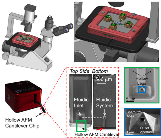
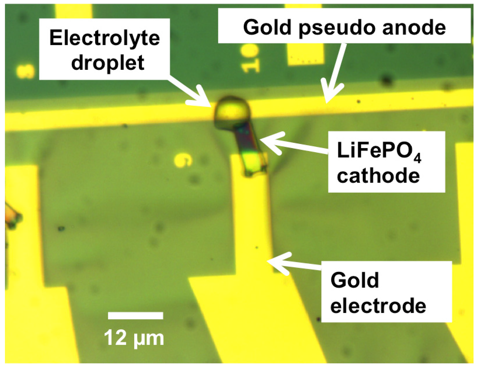
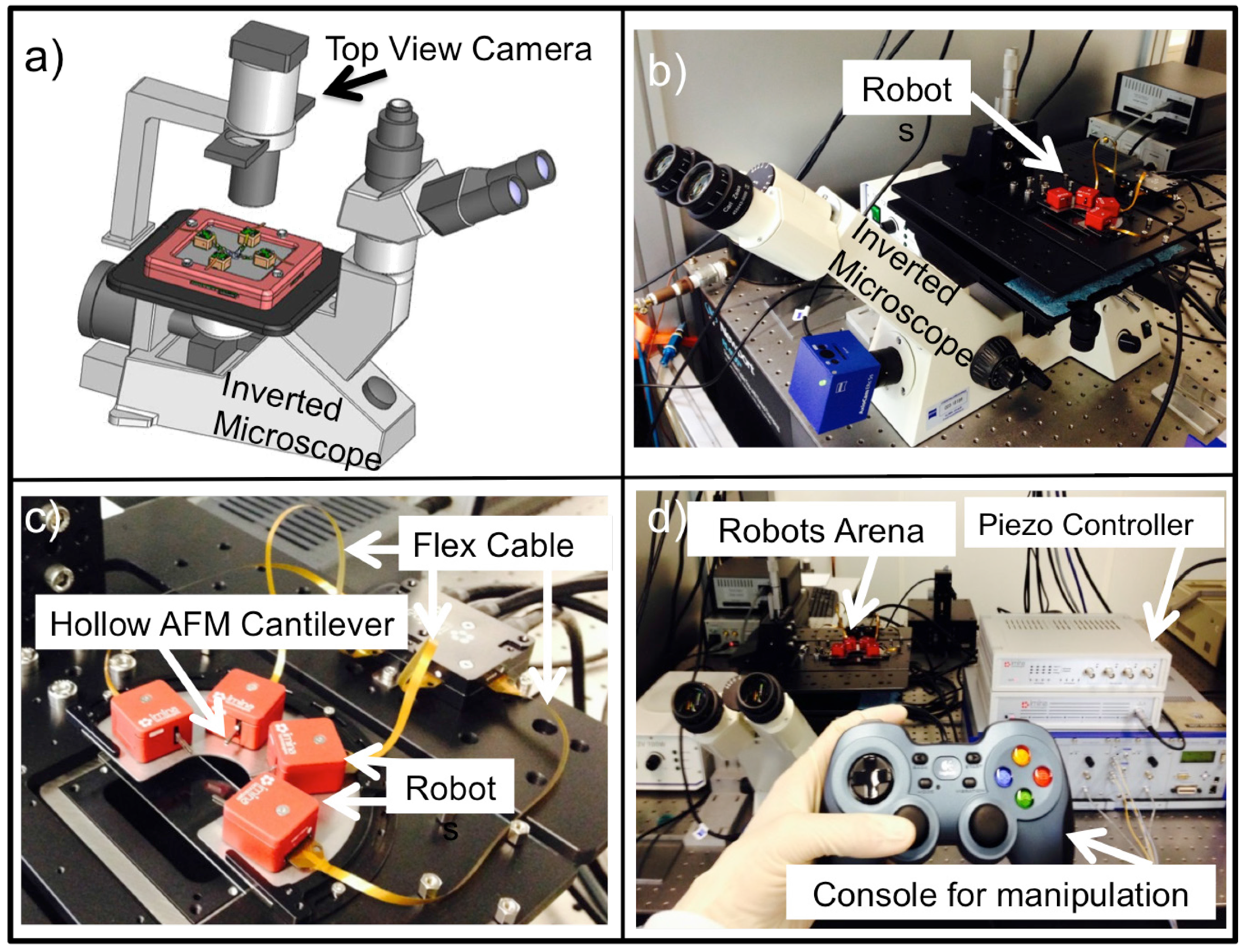
2.1. Nano-Workbench (NWB)

In order to achieve high precision and accuracy during manipulation, we used the commercially available robots (miBot) from Imina Technologies (Figure 1a). Such robot is a mobile nanomanipulator with 4 degrees of freedom (DoF), two translations and two rotations. It combines long traveling range displacements with nanometer resolution. This motion is obtained by using the piezo-actuators placed on the bottom-side of the robot (Figure 1b). These actuators can be operated in stepping mode or scanning mode. In the stepping mode, a stick-slip method is used to move the robots for large distances obtained with a series of small strokes each in the range of several hundreds of nanometers. In the scanning mode, a high-resolution motion of few nanometers within one step is obtained. The robot has a piezo-electric actuated arm that moves in the vertical direction. In order to equip the robot to perform fluid manipulations, the previously developed hollow AFM cantilever was mounted on the arm (Figure 1c). To make these devices, two silicon substrates with reservoir defined in one and hollow portion of the cantilever in the other were fused. Later, silicon dioxide layer was grown inside the hollow channels. Then, the cantilevers were released to form a transparent hollow AFM cantilever with a silicon nitride tip [6]. The device can be used to dispense liquids in the sub-femtolitre regime and image surfaces with the tip. As shown in Figure 1c, our device resembles a commercial AFM-chip, but with an inlet at the on-chip fluid reservoir located on one side, which is connected to an outlet located at the tip via the hollow cantilever on the other side. When the inlet is filled, the liquid travels through the integrated capillaries of the cantilever until the aperture at the AFM tip. The liquid was dispensed by capillarity obtained by bringing the cantilever in contact with the substrate. The interplay between the substrate surface energy and the surface tension of the liquid controlled the amount of liquid that was dispensed. Typically, the dispensing can be monitored from the force-distance curves in an AFM system, however, in our case, we do not have any in situ detection mechanism to monitor dispensing. The dispensing is monitored through a microscope by looking at the snapping of the cantilever tip to the substrate due to capillarity when it is taken very close to the substrate. Then, lifting the robot arm retracted cantilever leaving a droplet on the substrate. The chip was epoxy glued to the robotic arm in such way that the cantilever tip would always point downwards, such that the aperture located in the tip could be brought in touch with the intended sample/surface to manipulate. No additional external fluid connections were made to the chip.
Figure 1. Combined Hollow AFM cantilever and Robotic Nanomanipulator System. (a) The robot has four degrees of freedom that gives it the versatility to move and/or position the mounted chip in the required place. (b) The bottom side of the robot has three piezo actuators that can be operated to give the desired motion. (c) The chip was mounted on the arm in the front to obtain the desired out of plane motion. All the motions can be remotely controlled. The fluid reservoir is located on the topside and the cantilever is on the bottom-side. A desired liquid can be loaded in the fluid reservoir. (d) The hollow cantilever is connected to the on-chip reservoir through the microfluidic channels. In a close view of the hollow cantilever, an aperture near the tip is shown. The aperture is made using a focused ion beam on the side of the pyramid to preserve the sharp apex for imaging.
Micromachines 06 00600 g001
A control pad, which was plugged into a USB slot of the computer, allowed remote control of the nanomanipulators by increasing/decreasing the frequency and amplitude of the actuators for the vertical and horizontal motions. The external electronics, also plugged to the computer via a USB cable, was used for the control of piezoelectric actuators via flex cables. The robotic arena over which the robots were operating was made of a steel plate. An overview of the setup is shown in Figure 2. To monitor the performance of both the robot and hollow AFM cantilever during manipulation, the robotic arena is mounted either under an upright microscope with long working distance objectives or on top of an inverted fluorescence microscope to view through a transparent glass substrate and an additional top view camera. The speed and the resolution of positioning of the robot could be tuned by varying the frequency and the amplitude of the driving signals.
Figure 2. Nano-workbench. (a) Schematic of the working platform mounted on an inverted microscope with top view camera. (b) The picture of the setup. (c) Nanorobotic arena with four robots that can be operated in a time-multiplexed fashion. Robots are connected through a flex-cable to a hub, which in turn is connected to the computer. (d) The piezo controller and console for manipulation is shown.
Micromachines 06 00600 g002

2.2. Experiments with the Nano-Workbench

To demonstrate the capability and accuracy of using the NWB, we have performed three different experiments.
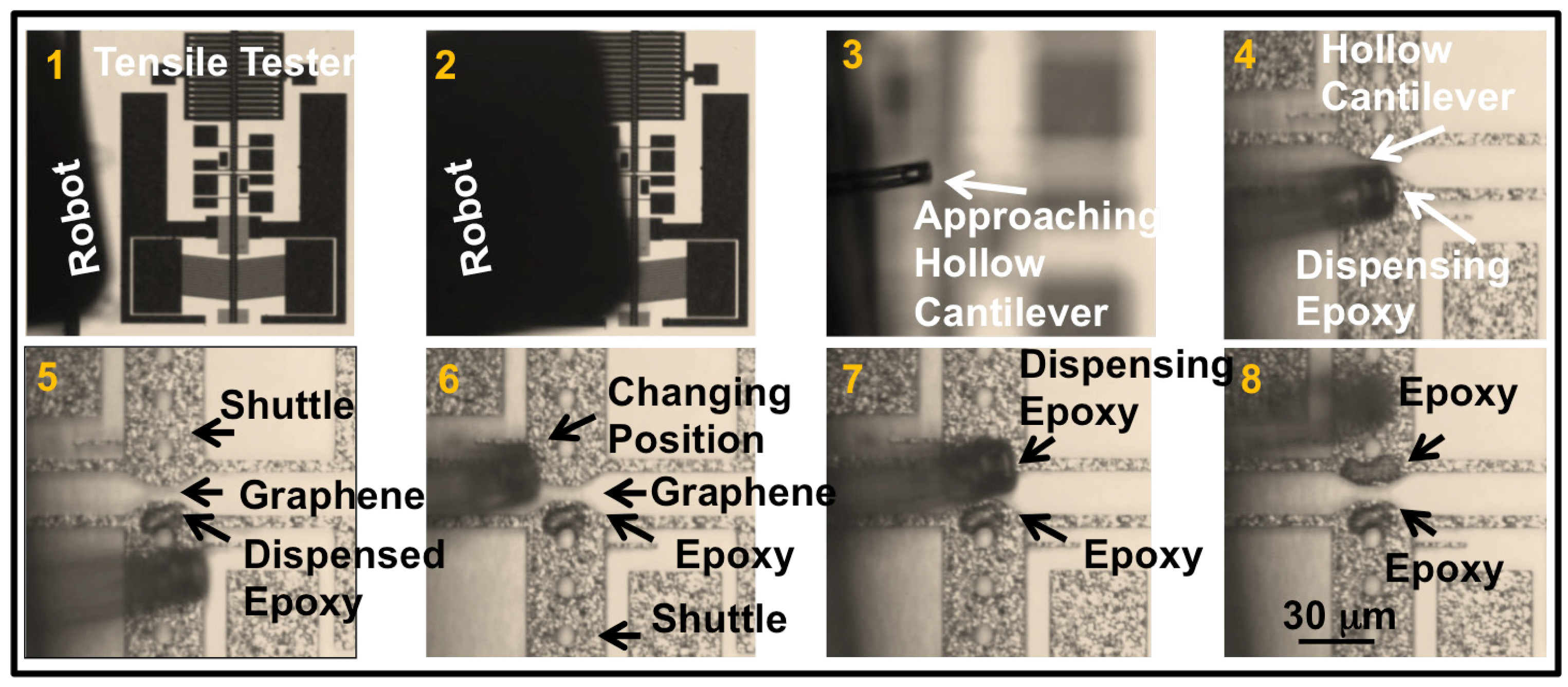
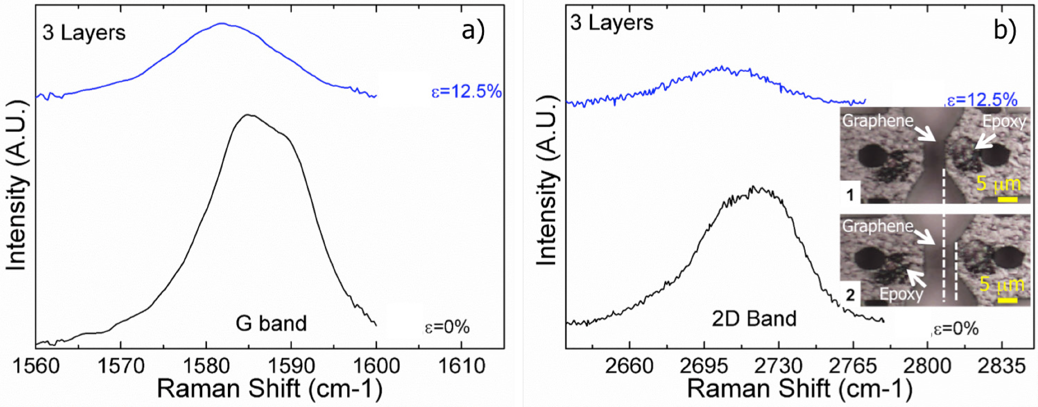
  • Clamping suspended graphene: In a micro-electro-mechanical system (MEMS) based tensile tester, there are two suspended shuttle beams with a separation of about 5 microns. The poly-silicon chevron-type thermal actuators connected to one of the shuttle pulled the sample suspended between the shuttle beams. Care was taken to keep the sample at room temperature with heat sinks attached to the shuttle. The detailed design and fabrication of the device is given elsewhere [6]. The sample under investigation for their tensile properties is placed between the shuttles to bridge the separation. In our experiment, we have transferred graphene between the shuttles. The van der Waals forces with the shuttle surface held the graphene. The shuttles were actuated such that the graphene would experience a tensile force. However, the graphene was always slipping away as the tensile force was overcoming the existing adhesion due to van der Walls forces between graphene and shuttle surface. To overcome this problem, clamping graphene was necessary. Using our NWB, we have locally dispensed epoxy on the shuttle-graphene interface present on both the shuttles of the MEMS device. The hollow cantilever was carefully brought to the point of interest by means of the remotely controlled robot. Once positioned in the vicinity of the graphene, the robot arm displaced the hollow cantilever slowly and accurately towards the edge of the graphene. Then, the hollow cantilever was snapped-in multiple times to locally dispense the epoxy along the edge of the shuttle over an area ranging about 10 μm × 10 μm (Figure 3). This area covered the entire graphene edge on the shuttle. The process was repeated on both edges, thus clamping graphene on both shuttles with epoxy. The graphene was stretched while recording the Raman spectra of the graphene. The 2D band and G band peaks were monitored in situ during stretching.
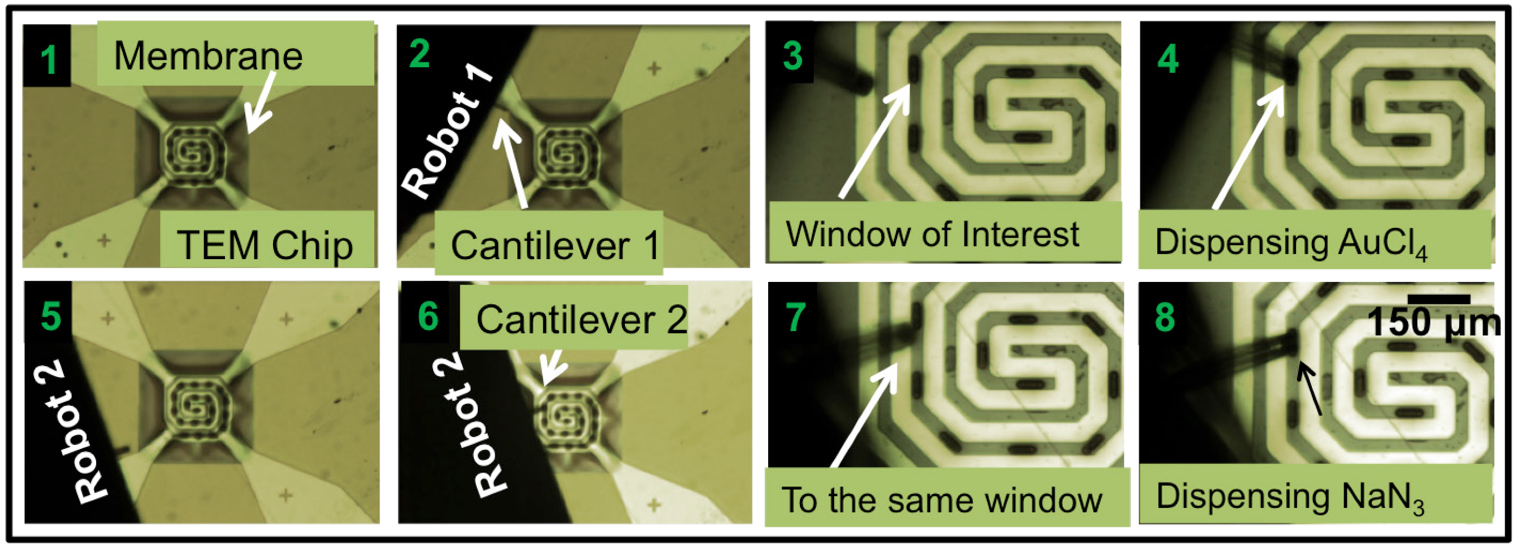
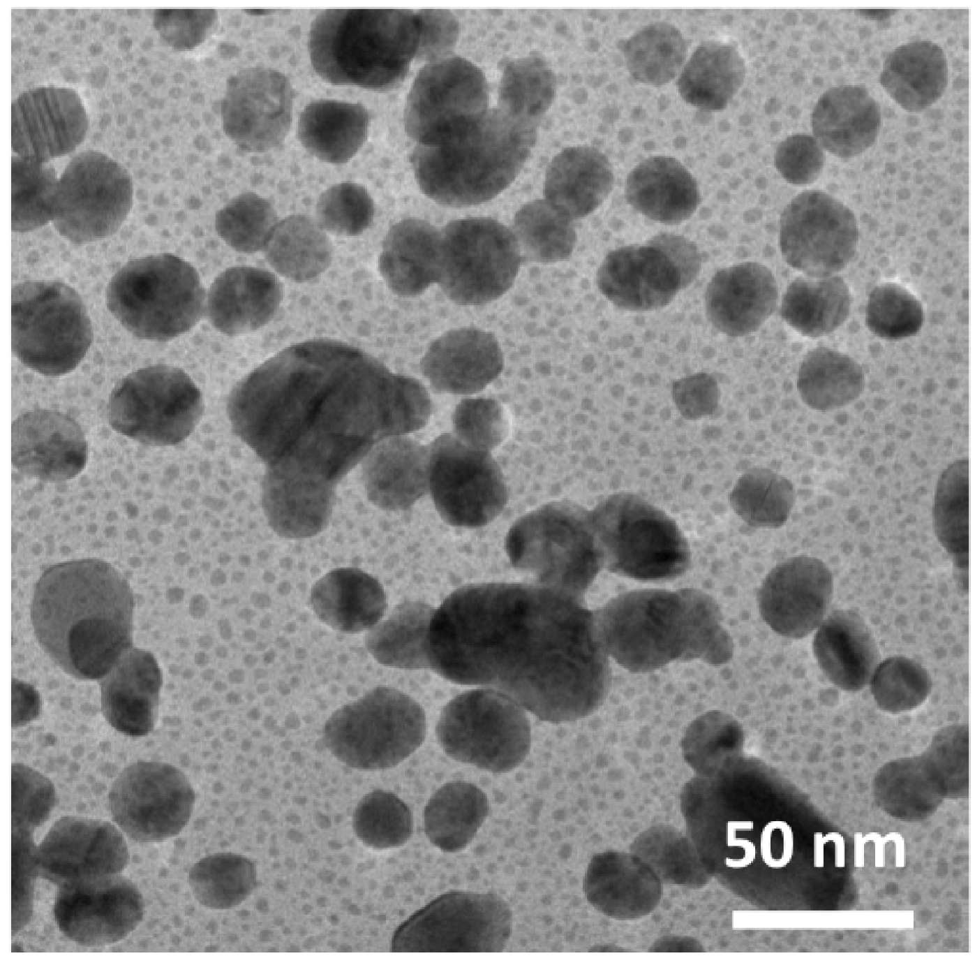
  • Mixing microdroplets: In this experiment, we have used the NWB to enable local deposition and controlled synthesis of gold nanoparticles. A chip containing a transmission electron microscopy (TEM) window of 50 nm thick Si3N4 and two different robots that were equipped with their own respective hollow cantilevers were used. One of them was filled with aqueous metallic salt solution (chloroauric acid–AuCl4), while the other was filled with aqueous reducing agent solution (sodium azide–NaN3). We first brought the robot carrying the metal salt solution near the TEM chip and approached the hollow cantilever towards the membrane window to dispense a droplet of controlled volume. After deposition, we brought the second robot containing the reducing agent and a droplet with the same volume was dispensed, allowing both reagents to coalesce and mix (Figure 4). Nanoparticles were synthesized in different droplet volumes ranging from 2.4 to 0.25 fL in equal quantities of both reagents on different windows. The results of the triggered chemical mixture were analyzed under TEM.
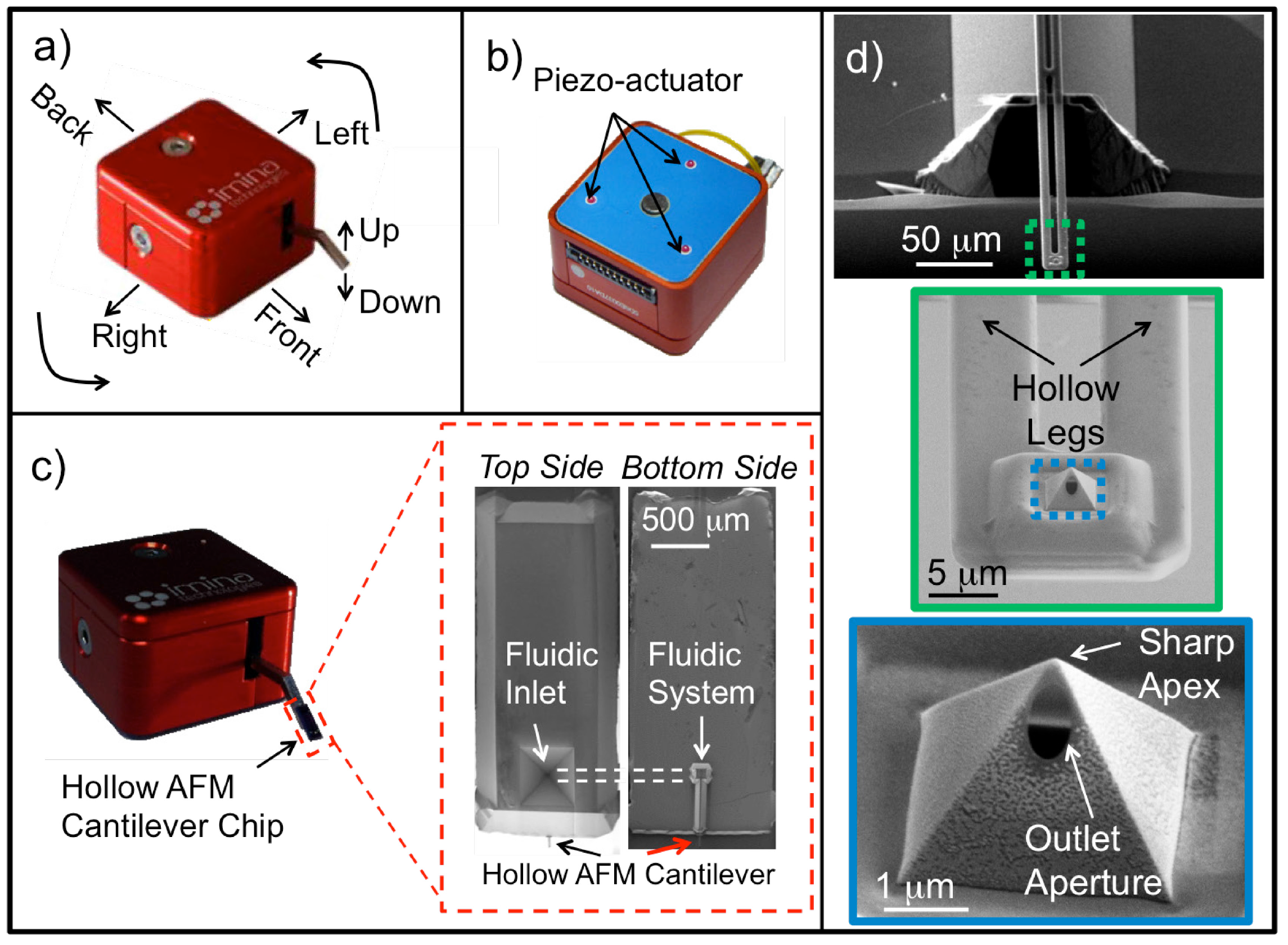
  • Dispensing electrolyte for nanobattery: In situ transmission electron microscope (TEM) with single grain electrode material can be used to visualize the lithium (de)intercalation process in real-time to understand the exact lithium transport mechanism inside the electrode material and thus better nanostructured electrode materials can be synthesized to improve the state of art lithium ion battery technology [6,13,14]. However, to prepare such a nanobattery assembly with single grain material, one needs to dispense tiny liquid electrolyte between the two electrodes with high accuracy [15]. The NWB was used to dispense not only tiny droplets of the ionic liquid (having low vapor pressure, stable in the high vacuum of TEM), namely 1 M lithium bis(trifluoromethane sulfonyl)imide (LiTFSI) in 1-Butyl-1-methylpyrrolidinium bis(trifluoromethylsulfonyl)imide, electrolyte but also precisely at the required position to complete the nanobattery assembly. Since the electrolyte was sensitive to air, dispensing was carried out inside the glove box, by placing the entire NWB setup inside the glove box. Battery assembly was made on a 20 nm silicon nitride membrane with appropriate electrical connections already fabricated before dispensing the electrolyte droplet.
Figure 3. Clamping of graphene on a MEMS device. The optical microscope images (1) to (8) are the snapshots of events happening during the process of clamping graphene with an epoxy. (1) The overview of MEMS tensile tester. By thermal expansion, one shuttle pulls the sample and the sample bridging the other shuttle moves. On-chip capacitive comb sensors detect motion of the shuttle. (2) Approaching with hollow cantilever to the location of dispensing. (3) Zoom into the approaching cantilever. (4) Dispensing epoxy on one of the shuttles. (5) Dispensed epoxy on one of the shuttle with graphene suspended between the shuttles. (6) Switching to the other shuttle. (7) Dispensing epoxy on the other shuttle. (8) The deposited epoxy on both shuttles, which eventually was cured and clamped the suspended graphene. The hollow cantilever attached to the robot arm was remotely controlled. The magnification for images (3) to (8) is same and the scale bar is given in (8).
Micromachines 06 00600 g003
Figure 4. Dispensing to mix two droplets of reagents to synthesis gold nanoparticles. The optical microscope images (1) to (8) are the snapshots of the events in time during dispensing of droplets on a 50 nm thin silicon nitride window. Scale bar for panels (3), (4), (7) and (8) is shown in panel (8). See supplementary material for the video.
Micromachines 06 00600 g004

3. Results and Discussion

The assembly of the NWB resulted in a well-mounted robotic arena on top of the inverted microscope that had an opened window in the center, such that the lens from the inverted microscope could have access to view the sample during manipulation. The robots were also portable enough to place them under upright microscope to visualize from top. The robots travel in two modes. On our setup, in the stepping mode, they made large distance motions covering a range of X: 25 mm, Y: 25 mm and Z: 8 mm, whereas in scanning mode they can be moved in the range of X: 150 nm, Y: 150 nm and Z: 300 nm. As for the positioning resolution, in stepping mode it was found to be X: 50 nm, Y: 50 nm and Z: 150 nm. Similarly, in scanning mode resolution was found to be X: 5 nm, Y: 5 nm, Z: 5 nm. The controller of the piezoactuators gave an output frequency of 0.7 Hz to 23.5 kHz and an output voltage ranging between 55–185 V (AC) and 0–185 V (DC).
The robots’ ability to position in a given spot and move the arm up and down was due to the piezoelectric actuators located under the robot. Basically, the actuators rely on inertia and friction, in a mode referred to as the stick-and-slip mode. Due to the typically limited displacement of the actuators, stick-slip offered the possibility to combine very high resolutions with very large range of displacements. Therefore, if the robot needed to be driven over large distances, the piezo-stick-slip actuator generated a series of small steps, each with hundreds of nanometers in displacement. This is also referred to as the stepping mode. When high resolution was needed, the robot could be positioned within one step with a resolution of a few nanometers depending on the input control used in the scanning mode.
With very low vapor pressure and high viscosity of the epoxy, dip and dispense technique was used for these experiments. The successful clamping of the graphene using the developed NWB, allowed achieving extreme strains in graphene, which were one order of magnitude higher than the previously reported values. Before clamping, a maximum strain of ~1.3% was obtained, after clamping we could achieve strains of ~12.5% (Figure 5). A significant decrease in the amplitude of the G-band and red shift in the 2D band are the signatures of the stretched graphene [16,17]. A detailed analysis of the above behavior is reported elsewhere [18]. Furthermore, tensile testing experiments were also performed on samples with various number of graphene layers suspended between the shuttles and clamping by epoxy. An unprecedented strains of 14% for monolayers and 11% for four layer graphene were obtained respectively and reported elsewhere [19].
Figure 5. Raman spectra of graphene showing signatures of 3 layers of graphene at G band and 2D band. The inset picture in the right panel is the image of the shuttles with graphene suspended between them before (1) and after stretching (2). The dashed lines are drawn as a guide to the reader indicating the displacement obtained with stretching resulting in a strain of 12.5% in graphene in the maximum stretched condition. (a) A shift in the G band with significant decrease in amplitude confirms the stretched graphene. (b) Similarly, a red shift in the 2D band also confirms the stretching of the graphene.
Micromachines 06 00600 g005
The experiments to synthesis gold nanoparticles on a thin silicon nitride membrane were performed in a non-condensing humid environment. The dispensed droplets being very small evaporated in less than a second without the humid environment. The volume of the dispensed droplet was separately measured using force distance curves on an AFM setup and reported elsewhere [20]. The local dispensing of the metal salt solution and reducing agent with equal volumes resulted in controlled synthesis of gold nanoparticles (Figure 6). Different droplet sizes were dispensed resulting in different sizes of synthesized nanoparticles. The dispensing of the droplet was by capillarity. The amount of volume dispensed depends on the surface energy of the substrate, surface tension of the liquid and the contact time during dispensing. A detailed analysis of the particle synthesis in such small droplets is reported elsewhere [20].
We could place the electrolyte drop with sub micron accuracy to prepare nanobattery for TEM experiments (Figure 7). During charging of the battery, Li+ ion will move out of the cathode, travel through the electrolyte and get deposited on the gold. While discharging, the Li+ will travel back to the cathode. Hence, the gold line pattern on the topside (see Figure 7) also acts as a pseudo anode.
Figure 6. TEM image of the synthesized nanoparticles obtained by mixing femtolitre volume droplets of chloroauric acid and sodium azide. The image was taken with particles on a 50 nm silicon nitride membrane.
Micromachines 06 00600 g006
Figure 7. Electrolyte droplet of ~6 μm dispensed on a 20 nm silicon nitride membrane to connect a lamella of 12 μm × 4 μm × 100 nm LiFePO4 cathode and gold pseudo anode electrode. The droplet is accurately dispensed between anode and cathode bridging a gap of 2 microns.
Micromachines 06 00600 g007

4. Conclusions

In conclusion, the hollow AFM cantilever mounted on a sugar cube sized robot can be used to locally and accurately dispense femtolitre volume liquid material on the target sites. A summary with the technical specifications of our NWB is shown in Table 1. Three experiments: Clamping of graphene on a MEMS tensile tester, synthesis of gold nanoparticles in femtolitre volume droplets on a 50 nm thin silicon nitride membrane and accurate dispensing of electrolyte droplets on a 20 nm thin silicon nitride membrane were performed to show the capabilities of the NWB. A significant improvement from 2% to 12.5% strain in three-layer graphene was obtained after clamping. As an outlook, the NWB provides an opportunity to study the mechanical properties (buckling, adhesion) of different samples (i.e., carbon nanotubes, graphene) and also to evaluate the behavior of a biological cell as a function of mechanical/chemical stimuli. By integrating piezoresistors on the attached hollow AFM cantilever [21], the amount of interface forces involved during fluid-fluid and fluid-surface interactions could be quantified. Furthermore, with on chip fluid reservoir interfaced to the external pressure control system, dispensing and aspiration can be well controlled. Other examples of manipulation of matter at this particular scale might include functionalization and assembly of micro and nano-electromechanical systems.
Table 1. Summary of technical specifications
Hollow AFM Cantilever
Resonance Frequency: 153.94 kHz
Spring Constant: 3.48 N/m
Typical Dispensed Volume: 30 fL
Storage Volume: 20 nL
Aperture Diameter: 300–2000 nm
Robot
Travelling Range
(a) Stepping Mode: X: 25 mm, Y: 25 mm, Z: 8 mm
(b) Scanning Mode: X: 150 nm, Y:150 nm, Z: 300 nm
Positioning Resolution
(a) Stepping Mode: X: 50 nm, Y: 50 nm, Z: 150 nm
(b) Scanning Mode: X: 5 nm, Y: 5 nm, Z: 5 nm
Controller
Output Frequency: 0.7 Hz to 23.5 kHz
Output Voltage: 55–185 V (AC) and 0–185 V (DC)

Acknowledgments

This work is supported by NanoNextNL, a micro and nanotechnology consortium of the government of the Netherlands and 130 partners.

Author Contributions

Héctor Hugo Pérez Garza, Murali Krishna Ghatkesar, Shibabrata Basak performed the experiments. Per Löthman contributed to gold nanoparticle synthesis chemistry. Urs Staufer conceived the idea of nano-workbench. Héctor Hugo Pérez Garza and Murali Krishna Ghatkesar wrote the manuscript. All authors commented and agreed with the content.

Supplementary Materials

The video shows the operation of two robotic arms in sequence to dispense liquids at desired location. Each robotic arm was attached with a hollow AFM cantilever. One was filled with aqueous metallic salt solution and the other with aqueous reducing agent solution. Dispensing was made on a 50 nm Si3N4 membrane. Supplementary materials can be accessed at: https://www.mdpi.com/2072-666X/6/5/600/s1.

Conflicts of Interest

The authors declare no conflict of interest.

References

  1. Research, I.A. Boy and His Atom: The World’s Smallest Movie. Available online: Http://www.research.ibm.com/articles/madewithatoms.shtml (accessed on 27 February 2015).
  2. Müller, D.J.; Dufrêne, Y.F. Atomic force microscopy: A nanoscopic window on the cell surface. Trends Cell. Biol. 2011, 21, 461–469. [Google Scholar] [CrossRef] [PubMed]
  3. Mohn, F.; Gross, L.; Moll, N.; Meyer, G. Imaging the charge distribution within a single molecule. Nat. Nanotechnol. 2012, 7, 227–231. [Google Scholar] [CrossRef]
  4. Li, G.; Xi, N. Overview of Nanomanipulation by Scanning Probe. In Introduction to Nanorobotic Manipulation and Assembly; Artech House: Norwood, MA, USA, 2012; pp. 93–110. [Google Scholar]
  5. Xi, N.; Fung, C.; Yang, R.; Seiffert-Sinha, K.; Lai, K.W.C.; Sinha, A.A. Bionanomanipulation using atomic force microscopy. IEEE Nanotechnol. Mag. 2010, 4, 9–12. [Google Scholar] [CrossRef]
  6. Ghatkesar, M.K.; Garza, H.H.P.; Staufer, U. Hollow AFM cantilever pipette. Microelectron. Eng. 2014, 124, 22–25. [Google Scholar] [CrossRef]
  7. Ghatkesar, M.K.; Garza, H.H.P.; Heuck, F.; Staufer, U. Scanning Probe Microscope-Based Fluid Dispensing. Micromachines 2014, 5, 954–1001. [Google Scholar] [CrossRef]
  8. Zambelli, T.; Meister, A.; Gabi, M.; Behr, P.; Studer, P.; Voros, J.; Niedermann, P.; Bitterli, J.; Polesel-Maris, J.; Liley, M.; Heinzelmann, H. Fluid FM: Combining Atomic Force Microscopy and Nanofluidics in a Universal Liquid Delivery System for Single Cell Applications and Beyond. Nano Lett. 2009, 9, 2501–2507. [Google Scholar] [CrossRef] [PubMed]
  9. Shibata, T.; Nakamura, K.; Horiike, S.; Nagai, M.; Kawashima, T.; Mineta, T.; Makino, E. Fabrication and characterization of bioprobe integrated with a hollow nanoneedle for novel AFM applications in cellular function analysis. Microelectron. Eng. 2013, 111, 325–331. [Google Scholar] [CrossRef]
  10. Kang, W.M.; Yavari, F.; Minary-Jolandan, M.; Giraldo-Vela, J.P.; Safi, A.; McNaughton, R.L.; Parpoil, V.; Espinosa, H.D. Nanofountain Probe Electroporation (NFP-E) of Single Cells. Nano Lett. 2013, 13, 2448–2457. [Google Scholar] [CrossRef] [PubMed]
  11. Xie, H.; Onal, C.; Régnier, S.; Sitti, M. Automated Control of AFM Based Nanomanipulation. In Atomic Force Microscopy Based Nanorobotics; Springer: Berlin, Germany, 2012; pp. 237–311. [Google Scholar]
  12. Hou, J.; Liu, L.; Wang, Z.; Wang, Z.; Xi, N.; Wang, Y.; Wu, C.; Dong, Z.; Yuan, S. Afm-based robotic nano-hand for stable manipulation at nanoscale. IEEE Trans. Autom. Sci. Eng. 2013, 10, 285–295. [Google Scholar] [CrossRef]
  13. Scrosati, B.; Garche, J. Lithium batteries: Status, prospects and future. J. Power Sources 2010, 195, 2419–2430. [Google Scholar] [CrossRef]
  14. Liu, X.H.; Huang, J.Y. In situ TEM electrochemistry of anode materials in lithium ion batteries. Energy Environ. Sci. 2011, 4, 3844–3860. [Google Scholar] [CrossRef]
  15. Wu, H.; Cui, Y. Designing nanostructured Si anodes for high energy lithium ion batteries. Nano Today 2012, 7, 414–429. [Google Scholar] [CrossRef]
  16. Mohiuddin, T.; Lombardo, A.; Nair, R.; Bonetti, A.; Savini, G.; Jalil, R.; Bonini, N.; Basko, D.; Galiotis, C.; Marzari, N. Uniaxial strain in graphene by Raman spectroscopy: G peak splitting, Grüneisen parameters, and sample orientation. Phys. Rev. B 2009, 79, 205433. [Google Scholar] [CrossRef]
  17. Ni, Z.H.; Yu, T.; Lu, Y.H.; Wang, Y.Y.; Feng, Y.P.; Shen, Z.X. Uniaxial strain on graphene: Raman spectroscopy study and band-gap opening. ACS Nano 2008, 2, 2301–2305. [Google Scholar] [CrossRef] [PubMed]
  18. Pérez Garza, H.H.; Kievit, E.W.; Schneider, G.F.; Staufer, U. Controlled, Reversible, and Nondestructive Generation of Uniaxial Extreme Strains (>10%) in Graphene. Nano Lett. 2014, 14, 4107–4113. [Google Scholar]
  19. Pérez-Garza, H.H.; Kievit, E.W.; Schneider, G.F.; Staufer, U. Highly strained graphene samples of varying thickness and comparison of their behaviour. Nanotechnology 2014, 25, 465708. [Google Scholar] [CrossRef] [PubMed]
  20. Garza, H.H.P.; Ghatkesar, M.K.; Löthman, P.; Manz, A.; Staufer, U. Enabling local deposition and controlled synthesis of Au-nanoparticles using a femtopipette. In Proceedings of the 2014 9th IEEE International Conference on Nano/Micro Engineered and Molecular Systems (NEMS), Waikiki Beach, HI, USA, 13–16 April 2014; pp. 323–328.
  21. Garza, H.; Stoute, R.; Ghatkesar, M.; Staufer, U. Self-sensing nanopipette for liquid dispensing and AFM imaging. In Proceedings of the 2013 Transducers & Eurosensors XXVII: The 17th International Conference on Solid-State Sensors, Actuators and Microsystems (TRANSDUCERS & EUROSENSORS XXVII), Madrid, Spain, 16–20 June 2013; pp. 2648–2651.

