Article

Extended Kalman Filter for Real Time Indoor Localization by Fusing WiFi and Smartphone Inertial Sensors

1
School of Information Science and Technology, Dalian Maritime University, Dalian 116026, China
2
Nanjing Research Institute of Electronics Technology, Nanjing 210039, China
*
Author to whom correspondence should be addressed.
Micromachines 2015, 6(4), 523-543; https://doi.org/10.3390/mi6040523
Submission received: 12 March 2015 / Revised: 11 April 2015 / Accepted: 20 April 2015 / Published: 22 April 2015
(This article belongs to the Special Issue Next Generation MEMS-Based Navigation—Systems and Applications)

Abstract

:
Indoor localization systems using WiFi received signal strength (RSS) or pedestrian dead reckoning (PDR) both have their limitations, such as the RSS fluctuation and the accumulative error of PDR. To exploit their complementary strengths, most existing approaches fuse both systems by a particle filter. However, the particle filter is unsuitable for real time localization on resource-limited smartphones, since it is rather time-consuming and computationally expensive. On the other hand, the light computation fusion approaches including Kalman filter and its variants are inapplicable, since an explicit RSS-location measurement equation and the related noise statistics are unavailable. This paper proposes a novel data fusion framework by using an extended Kalman filter (EKF) to integrate WiFi localization with PDR. To make EKF applicable, we develop a measurement model based on kernel density estimation, which enables accurate WiFi localization and adaptive measurement noise statistics estimation. For the PDR system, we design another EKF based on quaternions for heading estimation by fusing gyroscopes and accelerometers. Experimental results show that the proposed EKF based data fusion approach achieves significant localization accuracy improvement over using WiFi localization or PDR systems alone. Compared with a particle filter, the proposed approach achieves comparable localization accuracy, while it incurs much less computational complexity.

1. Introduction

Locating mobile objects enables various location based services [1] including object finding, human tracking, and emergency management, etc. In outdoor environments, Global Navigation Satellite Systems (GNSS) have been widely used in mobile devices and provided reasonable localization accuracy performance. Unfortunately, due to the GNSS signal attenuations, they are incapable of tracking indoors, where people spend the majority of their time. Though various indoor localization systems, such as WiFi localization using received signal strength (RSS) [2], ultra-wideband [3], radiofrequency identification (RFID) [4], and inertial sensors [5], have been developed, it is still a challenging task to provide accurate indoor localization with low cost.
WiFi localization systems using RSS have been considered as the most popular indoor localization approach due to its cost effectiveness. RSS readings can be easily collected by common smartphones with WiFi modules installed under the pervasively available WiFi infrastructures. The most widely used method for WiFi localization is a fingerprinting [6,7] based architecture. It collects RSS data from access points (APs) on predefined reference points to construct a database called radio map during offline phase, while it matches real time collected RSS with radio map to estimate the location during online phase. However, accurate localization results cannot be guaranteed by WiFi localization due to the severe RSS fluctuations [8,9] caused by complex indoor radio propagation conditions.
On the other hand, more and more smartphones with inertial sensors built in, including gyroscopes and accelerometers, make it feasible to deploy pedestrian dead reckoning (PDR) systems [10,11] in our daily lives. PDR systems estimate relative displacement by step detection and user heading estimation. If the initial user location is known, accurate absolute location estimation may be achieved when a pedestrian travels a short distance. In addition, PDR systems on smartphones are self-contained without requiring any external infrastructures. However, PDR systems incur drift error accumulations [12,13,14] along walking distances, especially for inexpensive but noisy inertial sensors built in smartphones.
Both systems mentioned above have their limitations and complementary strengths. WiFi localization systems provide necessary corrections for PDR systems to bind the accumulative drift errors, while PDR systems enable continuous tracking and smooth the localization results. Therefore, it is essential for indoor localization to fuse WiFi localization and PDR, which will obtain more significant performance improvement rather than deploying them alone.
Even though a lot of work [15,16,17,18,19,20,21,22] has been done in fusing both systems, some critical problems still need to be addressed to enhance accuracy and feasibility. On the one hand, previous data fusion approaches mainly focus on deploying a particle filter [18,19,20,21], which is computationally expensive and should be run on a server. However, rather than in a server, the localization system runs on a smartphone and is preferred due to its ability to protect the user’s privacy. Furthermore, the server based approaches involve a time consuming communication process, which is unsuitable for real time applications. On the other hand, light computation algorithms including Kalman filter and its variants cannot be directly deployed, since an explicit measurement equation and related noise statistics are not available. Therefore, it is a crucial task for real time indoor localization to develop a light computation fusion system run on resource-limited smartphones. In this paper, a novel data fusion framework based on extended Kalman filter (EKF) is firstly designed and implemented. In order to make EKF applicable, we develop a measurement model using kernel density estimation (KDE), which accurately characterizes the RSS-location relationship and adaptively measures the related noise statistics. For the PDR system, we accomplish another EKF for user heading estimation by fusing gyroscopes and accelerometers. In order to avoid singularity problems and reduce computation cost, we describe the device orientation by quaternions rather than Euler angles and direction cosine matrix (DCM). Experiments in a realistic indoor environment show that, the proposed EKF based fusion approach achieves significant accuracy improvement with respect to the individual approaches. Compared with a particle filter, the proposed EKF based fusion approach obtains comparable accuracy performance, while it reduces computation cost greatly.

2. Related Works

For indoor environments, though various localization approaches have been proposed, the optimal strategy is still an open issue. Recently, with the pervasive availabilities of WiFi infrastructures and low-cost inertial sensors built in smartphones, both WiFi localization and PDR systems have been considered as promising solutions for indoor localization. Consequently, due to their complementary strengths, fusing both systems has been paid increasing attention.
The earliest work fusing WiFi signals and inertial data is found in [18]. A particle filter is used to combine the pedestrian motion model, WiFi signals, and building maps. When the user’s current step is detected by an accelerometer, the estimated walking direction and step length are fed into the particle filter as a motion model to predict the new positions of particles. Then, the weight of a particle is updated by computing a Gaussian function of the Euclidean distance between the particle and the WiFi localization result, which is achieved by K-nearest neighborhood algorithm [23]. For PDR system, heading estimation is derived from the integration of gyroscope data, which are collected by a sensing box attached to the belt of a pedestrian. To compensate the integration drift error of heading estimation, a Kalman filter is deployed by fusing angles of the trajectory delivered in the WiFi localization system. Similar work can be found in [19], where a sequential importance resampling particle filter is applied to fuse a low-cost accelerometer, compass, and WiFi signals. Vertical acceleration signals are deployed to detect steps, while the user heading is obtained from a compass. In contrast to the particle updating scheme in [18], the weight of a particle is updated by the inverse Euclidean distance between real time collected RSS and RSS signals in the radio map.
In [20], Rai et al., propose an augmented particle filter, which simultaneously estimates location, step length, and user heading. For the PDR system, the user heading is firstly estimated by a compass, and then updated by the user’s trajectory in the measurement model of the augmented particle filter. For the WiFi localization system, the probability of observing real time RSS vector at the location of particles is computed as in [24], and then used to update the weight of particles. The key idea is that regular indoor layout information such as straight corridors may be exploited to correct the user’s path and related orientations. However, for a spacious indoor environment, there is always not enough layout information available, thus significantly degrading the performance of the augmented particle filter. In order to make the system as simple as possible to the user, instead of dedicated specific procedures, an auto-calibration procedure is further adopted in [21] to reduce the magnetic measurement errors. Though significant performance improvement is obtained, the calibration procedure model is founded on the two-dimensional horizontal plane and is inapplicable for the more common three-dimensional case.
Recently, a light computation approach based on Kalman filter is proposed in [22] to fuse PDR and WiFi localization. In real experiments, the proposed approach achieved significant improvements over individual approaches, while it reduced computation cost greatly. This approach formulates PDR as a linear function and considers the user heading estimated per step as known input vector without noise being introduced. As a result, significant estimation bias happens when Kalman filter computes the a priori error covariance of the state vector, thus degrading the performance of Kalman filter. For the WiFi localization system, the user location is estimated by the weighted coordinates of APs. The weights are normalized inverse physical distances between device and APs, which are computed by the RSS signal propagation model. Due to complex indoor radio propagation environment, the signal propagation model may be so inaccurate that little location information is obtained to correct PDR, especially when the number of APs available is limited and sparsely distributed in a large scale region.
Due to the heavy computational burden, the particle filter based approach should be run on a server and is unsuitable for real time applications. We propose a light computation fusion approach based on EKF. For heading estimation in the PDR system, instead of using a compass, we only deploy a gyroscope, since severe magnetic perturbations render poor performance of the compass in most indoor environments [25,26]. The perturbations are caused by universally available electromagnetic devices and magnetization of intricate modern structures, which include steel walls and concrete floors. Therefore, the perturbations always show complex patterns in terms of changing magnitudes and directions at different locations [26], and are difficult to be modeled and calibrated. Since gyroscopes can only provide relative heading change estimation, we assume that the user’s initial orientation is known as a priori in this paper. In fact, it can be obtained by various methods, such as Global Positioning System (GPS) tracking when pedestrians enter buildings [16], landmarks [27], and WiFi localization [28]. Furthermore, in order to guarantee accurate heading estimation from gyroscope data, a self-calibration procedure called “zero attitude updates” [29,30] is deployed to calibrate and compensate the gyroscope bias errors effectively. In our experiments, a zero attitude update, similar to the one implemented in [30], is performed just at the beginning of each experiment.
For device orientation representations of gyroscopes, there are mainly three kinds of descriptors: Euler angles [5], DCM [31], and quaternions [29]. The Euler angle based method is conceptually easy to understand, but it is computationally expensive and incurs singularity problems [32]. Both DCM and quaternion based methods may avoid the singularity problems. However, the quaternion based method requires much less computations than DCM, since it is easier to be normalized and needs only four variables updated during state propagating procedure. Therefore, we deploy quaternions for device orientation representations. Furthermore, to compensate the heading estimation drift caused by the tilt of hand-held smartphones, we develop an EKF to fuse the three dimensional gyroscope and accelerometer signals, which may infer tilt angles of smartphones.
For the WiFi localization system, due to various factors, such as obstacles, human body attenuations, and multi-path effects, it is impossible to construct an explicit equation for characterizing RSS-location relationship [24]. In [33], a stochastic model is developed to characterize the RSS-location relationship, with the posterior density approximated by a particle filter. In this paper, we deploy KDE [34] for density estimation to develop a RSS-location measurement model. The developed model may adaptively measure the noise statistics of WiFi localization, which cannot be achieved by previous fusion approaches. Besides, we further reduce the computation cost by restricting WiFi localization into the vicinity of the estimated location of the previous user step. Therefore, as shown in our experimental results, the proposed EKF based fusion approach obtains comparable accuracy in comparison to a particle filter, while it reduces computational complexity greatly.

3. Methodology

Figure 1 presents the architecture of the proposed EKF based fusion approach on smartphones. The proposed approach includes two EKFs. The first EKF is used to integrate gyroscope with accelerometer for heading estimation of PDR. The second EKF achieves the location estimation by fusing the WiFi localization system and PDR system. The measurement model of the second EKF is the developed RSS fingerprinting algorithm based on KDE. In addition, a spatial filtering process is introduced to restrict the WiFi localization into a sub-region. The state model of the second EKF is the PDR system, which comprises step detection, step length estimation, and quaternion based heading estimation modules.
Figure 1. Architecture of the proposed extended Kalman filter (EKF) based fusion approach.
Micromachines 06 00523 g001

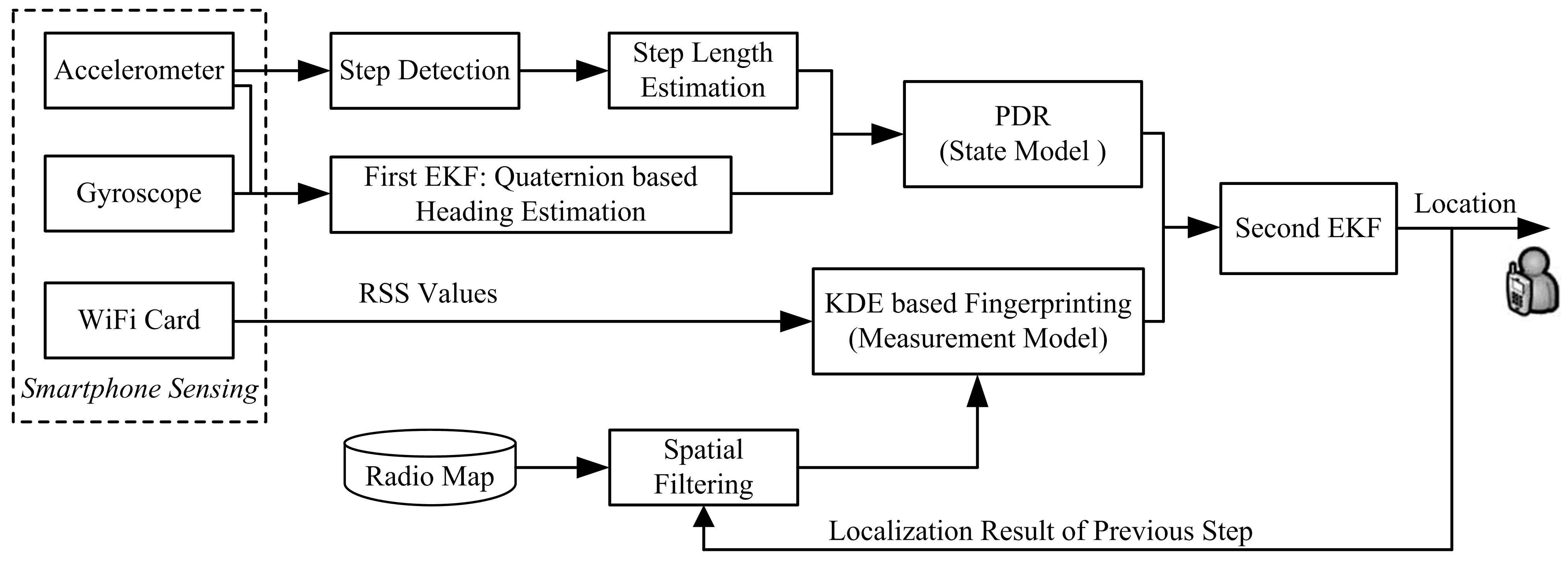
3.1. Pedestrian Dead Reckoning

We deploy the smartphone inertial sensors, including an accelerometer and a gyroscope, for pedestrian dead reckoning. Theoretically, the pedestrian walking distance can be obtained by the double integration of acceleration signals. However, this approach suffers from unbounded error growth due to sensor noises. An effective solution is the PDR approach, which detects the walking step, estimates the step length and user heading. Thus, the position of the current step can be determined by the position of a previous step as follows:
L i  =  L i 1  +  d i [  cos( ψ ˜ i ) sin( ψ ˜ i ) ]
where L i  =  ( x i , y i ) is the estimated coordinates of the i th step, d i is the estimated step length of the i th step, and ψ ˜ i is the estimated user heading. In this paper, we assume that the initial user’s location and walking direction are known, which can be obtained by various methods, such as the user’s input [11] and GPS tracking when a pedestrian enters a building [16].

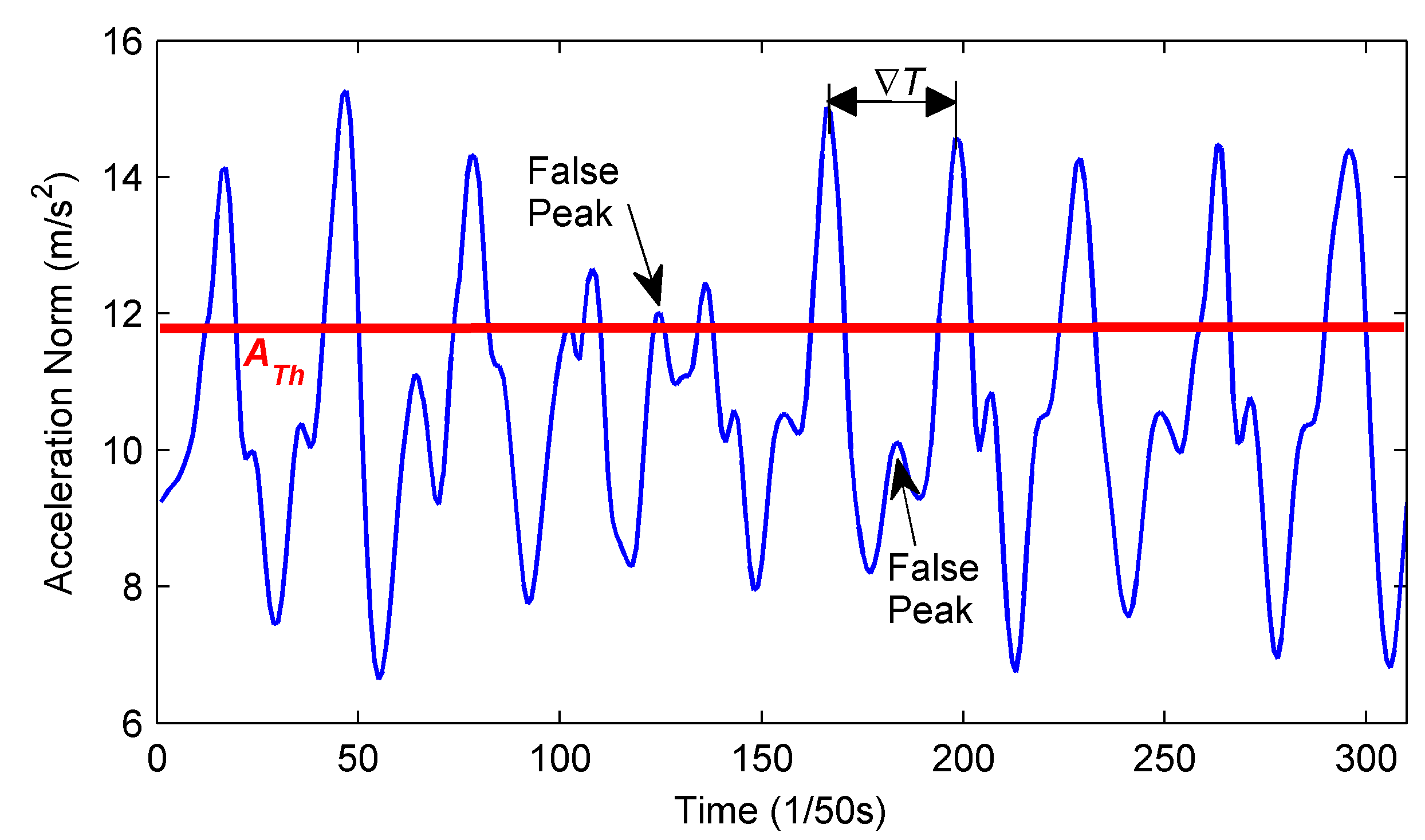
3.1.1. Step Detection and Step Length Estimation

Steps can be detected based on periodic acceleration fluctuation patterns during walking. To avoid the negative effect of the accelerometer unit tilt, we deploy the norm of measured three dimensional acceleration signals for step detection, since the pattern of acceleration signal norm is insensitive to different device orientations. To reduce the acceleration signal noise, a smoothing function [22] is deployed to average the raw acceleration data. After smoothing the raw data, a peak detection algorithm is applied to identify a distinct step, as shown in Figure 2. Two thresholds are used to filter out false peaks caused by acceleration jitters with too small magnitude or too short time intervals,
{ Δ T T Th | A c c N o r m g | A Th
where Δ T is the time interval between adjacent peaks, A c c N o r m is the norm of the measured three dimensional acceleration signal, g is the value of local gravity, T Th and A Th represent the time threshold and the magnitude threshold for peak detection, respectively. Practically, the time threshold is set around two-thirds of the walking period. The false peak with a small magnitude will be easily filtered out by the magnitude threshold A Th . For the false peak with a magnitude exceeding A Th , the motion law of the pedestrian walking makes the time interval between it and true peak within one step much shorter than the time threshold, and thus they can be easily distinguished between each other [11,12]. As shown in Figure 2, the marked false peak exceeding A Th will be firstly considered as a peak for a new step, if the time interval between it and the previous peak exceeds the time threshold. Then, this will be corrected by the following true peak with bigger magnitude and shorter time interval than the time threshold.
Figure 2. Peak detection based on periodic patterns of the acceleration norm.
Micromachines 06 00523 g002
The step lengths are determined by various factors, including height, attitude, and walking frequency [11,35]. Since step length models for different pedestrians vary a lot, it is difficult to develop a generic model that is accurate for all pedestrians. For the same person, the step length mainly depends on the walking speed. Therefore, we apply the empirical model [36] to estimate the step length in Equation (1) as follows:
d i = C 1 A c c max i - A c c min i C
where A c c max i and A c c min i represent the maximum and minimum of acceleration signal norms for step i , C and C 1 are the personalized coefficients for different pedestrians. The coefficients can be easily estimated by counting steps when pedestrians travel a known distance.

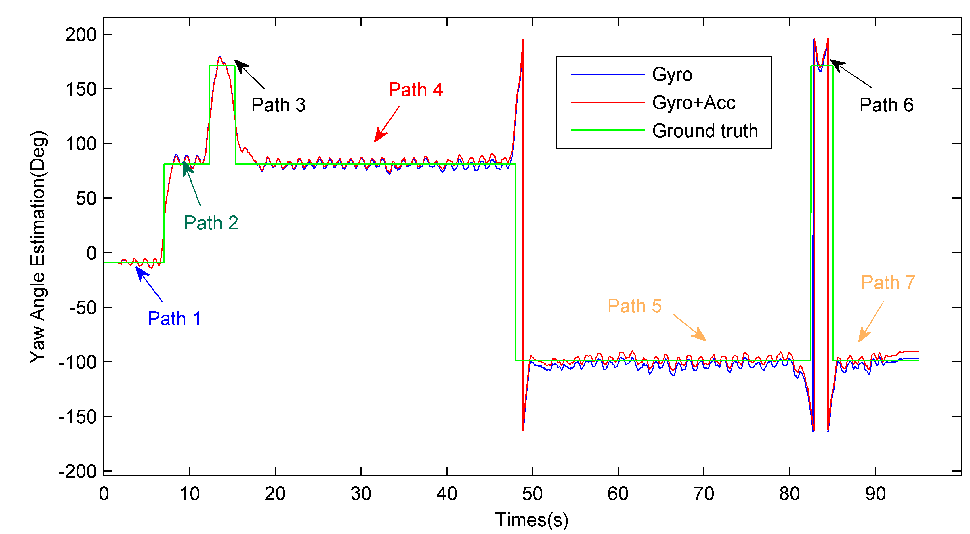
3.1.2. First EKF: Quaternion Based Heading Estimation

All inertial data, including three dimensional accelerations and angular velocities, are measured in a right-handed body frame B attached to the smartphone by axes X B , Y B and Z B . Define the front face of the screen as a plane F R . The X B axis is parallel to F R and points to the right; The Y B axis is parallel to F R and points forward; The Z B axis is perpendicular to F R and points outside of F R . Thus, the orientation of a smartphone is determined when the axis orientation of the frame B is specified with respect to the absolute coordinate system called navigation frame N A . Note that, during walking, the user heading may be different from the smartphone forward when a smartphone is put in a pocket or a bag. This paper only considers the most common hand-held situation [17,18,19], in which the smartphone is held in a hand faced in front. The smartphone’s forward axis is always the same as the user’s walking direction at the horizontal level frame. Therefore, we assume that the smartphone forward and the user heading are aligned in the same direction.
We apply rotation quaternion to describe the time model of smartphone orientations, since it can avoid the singularity problems and require the least computations [32]. First, we construct the relationship between a quaternion and the smartphone orientation. The transformation from frame N A to B can be represented as follows:
h b ( t ) = C n b ( q ( t ) ) h n ( t )
where C n b ( q ( t ) ) is the direction cosine matrix (DCM), h b ( t ) and h n ( t ) is the 3 × 1 column-vector at time t relative to B and N A . For the sake of simplicity, the argument t will be omitted. We deploy the rotation quaternion to describe the DCM,
C n b ( q ) [ q 0 2 + q 1 2 q 2 2 q 3 2 2 ( q 1 q 2 + q 0 q 3 ) 2 ( q 1 q 3 q 0 q 2 ) 2 ( q 1 q 2 q 0 q 3 ) q 0 2 q 1 2 + q 2 2 q 3 2 2 ( q 0 q 1 + q 2 q 3 ) 2 ( q 1 q 3 + q 0 q 2 ) 2 ( q 2 q 3 q 0 q 1 ) q 0 2 q 1 2 q 2 2 + q 3 2 ]
where q [ q 0 q 1 q 2 q 3 ] T is the normalized orientation quaternion, q 0 is the scalar part and q 1 , q 2 , q 3 is the vector part of the quaternion. Therefore, the orientation of a smartphone with respect to navigation frame N A is described by three angles as follows:
{ y a w = arctan ( 2 ( q 0 q 3 q 1 q 2 ) / ( q 0 2 q 1 2 + q 2 2 q 3 2 ) ) p i t c h = arcsin ( 2 ( q 2 q 3 + q 0 q 1 ) ) r o l l = arctan ( 2 ( q 0 q 2 q 1 q 3 ) / ( q 0 2 q 1 2 q 2 2 + q 3 2 ) )
Secondly, according to the rigid body kinematic equations [32], the discrete-time model of orientation quaternions can be given as:
q k + 1  =  exp ( 0.5 × Ω ( w k T s ) ) q k = ( I cos ( 0.5 × Δ θ k ) + Ω ( w k T s ) sin ( 0.5 × Δ θ k ) / Δ θ k ) q k
where T s is the system interval, w k = [ w k x w k y w k z ] T is the output of gyroscope at time instants k T s , I is an identity matrix, Δ θ k = T s ( w k x ) 2 + ( w k y ) 2 + ( w k z ) 2 , q k and q k + 1 are the quaternions at time instants k T s and ( k + 1 ) T s respectively, Ω ( w k T s ) is given as follows:
Ω ( w k T s ) = T s [ 0 w k x w k y w k z w k x 0 w k z w k y w k y w k z 0 w k x w k z w k y w k x 0 ]
The quaternion at time instants ( k + 1 ) T s is determined, starting from initial conditions q 0 that may be calculated by initial known orientation of the smartphone.
Finally, the EKF is applied to fuse gyroscopes with accelerometers for heading estimation. We deploy the rotation quaternion of a smartphone as the state vector, and thus the state transition vector equation is:
q k + 1  =  F k q k + w k q
where state transition matrix F k = exp ( Ω ( w k T s ) ) , and
w k q = Ξ k w k g y r o = T s 2 [ [ e k × ] + q 0 k I e k T ] w k g y r o
where q 0 k is the scalar part of the quaternion q k [ q 0 k q 1 k q 2 k q 3 k ] T at time instants k T s , e k [ q 1 k q 2 k q 3 k ] T is the vector part of q k , I is the 3 × 3 identity matrix, w k g y r o is the white Gaussian measurement noise vector for Gyroscope at time instants k T s , and [ e k × ] is a standard vector cross-product operator:
[ e k × ] = [ 0 q 3 k q 2 k q 3 k 0 q 1 k q 2 k q 1 k 0 ]
Equations (9) and (10) are derived from Equation (7) and can be considered as a first order approximation of the “noisy” transition matrix. The gyroscope measurement noise vector w k g y r o is assumed small enough in the application area, thus the first order approximation always performs well. Therefore, the process noise covariance matrix Q k can be given as follows:
Q k  =  Ξ k Q k g y r o Ξ k T
where Q k g y r o = σ g y r o 2 I is the covariance matrix for w k g y r o .
The measurement model is constructed by observed acceleration vectors,
a k + 1  =  C n b ( q k + 1 ) g + v k + 1 a
where a k + 1 is the acceleration vector of the smartphone, g is the local gravity vector relative to N A , and v k + 1 a is the white Gaussian measurement noise of the accelerometer. Note that Equation (13) is true only when the human body is not affected by any acceleration. Assume that the covariance matrix of the measurement noise v k + 1 a is R ˜ k + 1 . To filter out the disturbance of significant human motions, we construct adaptive measurement covariance matrix R ˜ k + 1 = σ a 2 R I ,
σ a 2 R = { σ a 2 , a k + 1 g 2 < ε a , otherwise
Because of the nonlinearity of Equation (13), the EKF approach linearizes the first part on the right side of Equation (13) by computing the Jacobian matrix:
H k + 1 = q k + 1 a k + 1 | q k + 1 = q k + 1 , v k + 1 a = 0
where the true state q k + 1 is not known; it is reasonable to replace the true state with the best estimate of the state available, namely the a priori state estimate q k + 1 . Thus, the measurement model can be approximated as a linearized formula:
a k + 1     H k + 1 q k + 1 H k + 1 q k + 1 + C n b ( q k + 1 ) g + v k + 1 a
Based on the state model in Equation (9) and the linearized formula of the measurement model in Equation (16), the a posteriori estimation of the quaternion q ^ k + 1 and the corresponding covariance matrix P q k + 1 may be obtained by the first EKF. The detailed procedures for the first EKF are given as follows:
Firstly, compute the a priori state estimation and related error covariance matrix:
q k + 1 = F k q ^ k
P q k + 1 = F k P q k F k T + Q k
where q ^ k is the a posteriori estimation of the quaternion at time instants k T s , and P q k is the related error covariance matrix.
Then, compute the Kalman gain:
K k + 1 = P q k + 1 H k + 1 T ( H k + 1 P q k + 1 H k + 1 T + R ˜ k + 1 ) 1
Finally, compute the a posteriori state estimate and related error covariance matrix:
q ^ k + 1 = q k + 1 + K k + 1 ( a k + 1 C n b ( q k + 1 ) g )
P q k + 1 = P q k + 1 K k + 1 H k + 1 P q k + 1
After obtaining q ^ k + 1 , the user heading at time instants ( k + 1 ) T s is ultimately determined as in Equation (6). More detailed descriptions about the EKF process can be found in [37].

3.2. WiFi Localization Based on Kernel Density Estimation

In this section, we propose the KDE based WiFi localization for measurement update. Due to the lack of explicit measurement equation and related noise statistics, WiFi localization cannot be directly deployed for measurement update in EKF. Instead of an explicit measurement equation, we note that the density function may accurately characterize the RSS-location relationship. Assume that r is the real time RSS vector collected by the user, l is the user’s coordinate vector, and the posterior density of the user’s location is f ( l | r ) . If we know f ( l | r ) , Minimum Mean Squared Error (MMSE) [37] location estimation and its covariance matrix can be given as follows:
l ^ = l f ( l | r ) d r
P r = ( l l ^ ) ( l l ^ ) T f ( l | r ) d r
However, the posterior density is unavailable in WiFi localization. To solve this problem, we propose KDE for approximating the posterior density due to its success in probability density distributions estimation. Given the radio map storing RSS training pairs { ( r ¯ i , l i ) | i = 1 , , N } with mean RSS vector r ¯ i at the reference point l i , and a Gaussian kernel , the posterior density estimation [34] is given as follows:
f ^ ( l | r ) = f ^ ( l , r ) f ^ ( r ) = i = 1 N ( r ; r ¯ i , Σ r ) ( l ; l i , Σ l ) i = 1 N ( r ; r ¯ i , Σ r ) = i = 1 N w ˜ i ( r ) ( l ; l i , Σ l )     
w ˜ i ( r ) = ( r ; r ¯ i , Σ r ) i = 1 N ( r ; r ¯ i , Σ r )
where N is the number of reference points at the target region, r ¯ i and l i are mean vector of the Gaussian kernels, and diagonal matrices Σ r and Σ l are the related covariance matrices, respectively. Essentially, the estimated probability density is a Gaussian mixture, whose first two moments [34] are:
l ^ = i = 1 N w ˜ i ( r ) l i
P r = i = 1 N w ˜ i ( r ) ( Σ l + ( l i l ^ ) ( l i l ^ ) T )
Equations (26) and (27) can be used for measurement update and the corresponding covariance of the second EKF, respectively.
Besides, to reduce the number of reference points involved in WiFi localization for measurement update, we deploy a spatial filtering process. The spatial filtering assumes that the pedestrian walking distance between adjacent steps cannot exceed a predefined distance threshold. Thus, we restrict the reference points involved in WiFi localization into a sub-region, whose centre is the localization result of the previous step and the radius is the distance threshold. Define that L ^ i 1 is the localization result by the proposed fusion approach at the i 1  th step, D Th is the distance threshold between adjacent steps, then a set of reference points involved in WiFi localization at the i th step can be given as follows:
S i _ s t e p = { ( r ¯ i , l i ) |   l i L ^ i 1 2 D Th ; i = 1 , , N }
Denote the cardinality of S i _ s t e p as N i _ s t e p , which is much smaller than N. Then, the spatial filtering process may effectively reduce the computation cost for measurement update of the second EKF by reducing the number of reference points involved.

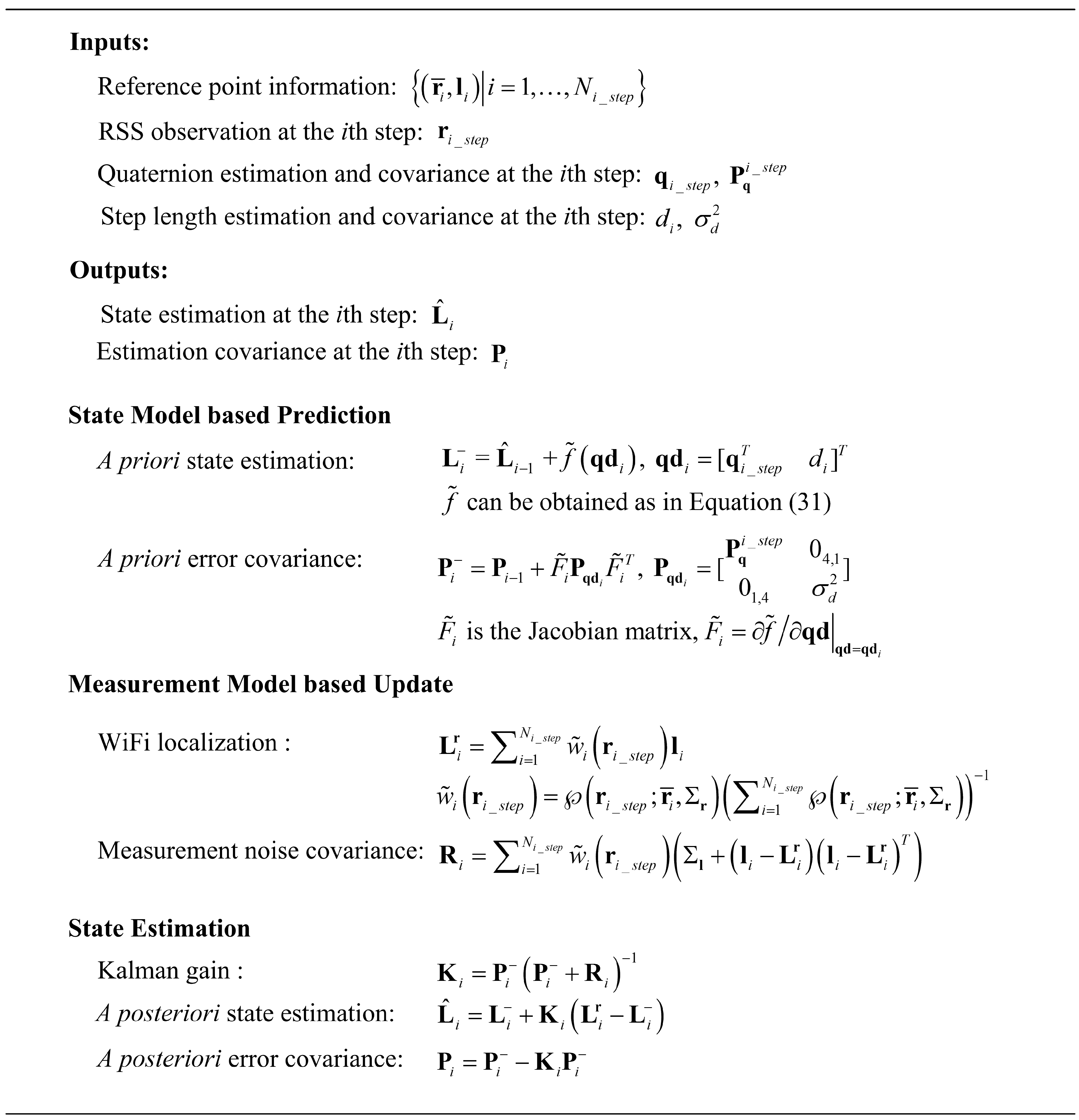
3.3. Second EKF: Fusing PDR and WiFi Localization
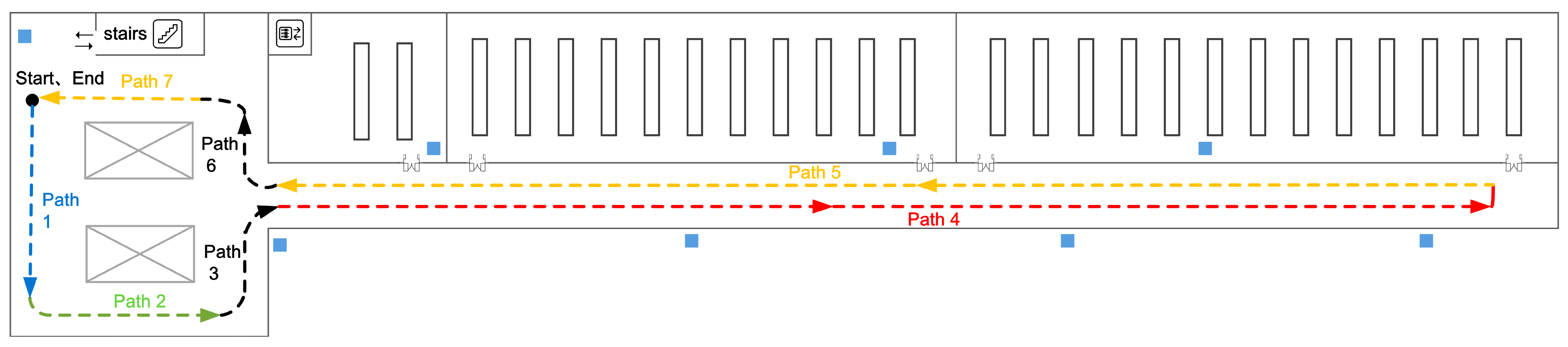
PDR and WiFi Localization systems both have their limitations and advantages. The PDR system can obtain relative displacement with high accuracy in a short period, while it suffers from cumulative drift errors during walking. The WiFi localization system can provide the absolute location estimation, while it incurs the inaccurate localization results when significant RSS fluctuations happen. Fusing both systems will exploit their complementary advantages. PDR enhances the accuracy of WiFi localization, while WiFi localization is useful for binding the cumulative PDR drift errors.
The most widely used fusion approach is a particle filter, which incurs substantial computation cost. It is unsuitable for real time indoor localization on resource-limited smartphones. Moreover, Kalman filter and its variants cannot be directly used since an explicit measurement equation and RSS noise statistics are unavailable. To make the proposed light computation EKF based approach applicable, Section 3.2 proposes a measurement model based on KDE. This section describes the detailed process of the proposed fusion approach. The complete summary of the second EKF is shown in Figure 3.
First, we give the formula of state model. Assume ψ i _ s t e p is the yaw angle estimated at the i th step from Equation (6) in the navigation frame NA, and ψ x _axis is the yaw angle of a predefined positive x-axis, whose definition is shown in Figure 4 in our experiments. Define ψ ˜ i as the anticlockwise rotation angle from the predefined positive x-axis to the user walking direction. Then, PDR model can be rewritten by substituting ψ ˜ i = ψ i _ s t e p ψ x _axis into Equation (1):
L i  =  L i 1  +  d i [  cos(ψ i _ s t e p )cos(ψ x _axis )+sin(ψ i _ s t e p )sin(ψ x _axis ) sin(ψ i _ s t e p )cos(ψ x _axis ) sin(ψ x _axis )cos(ψ i _ s t e p ) ]
where ψ i _ s t e p is obtained at the acceleration peak time of the i th step. Note that if the navigation frame NA is aligned with the predefined coordinate, the PDR model will be simplified and the same as Equation (1), since ψ ˜ i is equal to ψ i _ s t e p . We give the more general PDR model, because the predefined coordinate system may be different for different pedestrians according to the personalized requirements, especially for a large scale localization region. For cos( ψ i _ s t e p ) and sin( ψ i _ s t e p ) , they can be obtained from Equation (6):
{ cos ( ψ i _ s t e p ) = ( 1 2 ( q 1 i _ s t e p ) 2 2 ( q 3 i _ s t e p ) 2 ) ( 1 4 ( q 0 i _ s t e p q 1 i _ s t e p + q 2 i _ s t e p q 3 i _ s t e p ) 2 ) 0.5 sin ( ψ i _ s t e p ) = ( 2 q 0 i _ s t e p q 3 i _ s t e p 2 q 1 i _ s t e p q 2 i _ s t e p ) ( 1 4 ( q 0 i _ s t e p q 1 i _ s t e p + q 2 i _ s t e p q 3 i _ s t e p ) 2 ) 0.5
where q i _ s t e p = [ q 0 i _ s t e p q 1 i _ s t e p q 2 i _ s t e p q 3 i _ s t e p ] T is the quaternion estimated by the first EKF at the acceleration peak time of the i th step. Then, we rewrite Equation (29) as:
L i  =  L i 1  +  f ˜ ( q d i )
where f ˜ ( ) is the relative displacement function of q d i = [ q i _ s t e p T d i ] T , and can be obtained by substituting Equation (30) into the second part on the right side of Equation (29).
Secondly, compute the a priori state estimation L i and the a priori error covariance matrix P i ,
L i  =  L ^ i 1  +  f ˜ ( q d i )
P i = P i 1 + F ˜ i P q d i F ˜ i T
where L ^ i 1 is the a posteriori location estimation at the i 1  th step, F ˜ i = f ˜ / q d is the Jacobian matrix computed at q d = q d i , P i 1 is the a posteriori error covariance matrix at the i 1  th step,
P q d i = [ P q i _ s t e p 0 4 , 1 0 1 , 4 σ d 2 ]
where 0 i , j is the i × j all-zeros matrix, P q i _ s t e p is the a posteriori error covariance matrix of q i _ s t e p , and σ d 2 is the covariance of the estimated step length.
Thirdly, we apply the KDE based RSS measurement model proposed in Section 3.2,
L i  =  L i r
where L i r is the WiFi localization result using RSS vector r i _ s t e p , which is the averaged RSS vector of samples collected during the i th step. Similar to Equations (26) and (27),
L i r = i = 1 N i _ s t e p w ˜ i ( r i _ s t e p ) l i
R i = i = 1 N i _ s t e p w ˜ i ( r i _ s t e p ) ( Σ l + ( l i L i r ) ( l i L i r ) T )
where R i is the measurement noise covariance matrix, ( r ¯ i , l i ) S i _ s t e p is the training pairs involved at the i th step derived from Equation (28), N i _ s t e p is the number of reference points used.
Finally, the location at the i th step can be estimated by fusing state model in Equation (31) and measurement model in Equation (35). The Kalman gain can be given as follows:
K i = P i ( P i + R i ) 1
Then, the a posteriori location estimation at the i th step is given as follows:
L ^ i = L i + K i ( L i r L i )
The corresponding a posteriori error covariance matrix is given as follows:
P i = P i K i P i
Figure 3. Summary of the second EKF for fusing WiFi localization and PDR.
Micromachines 06 00523 g003

4. Evaluation

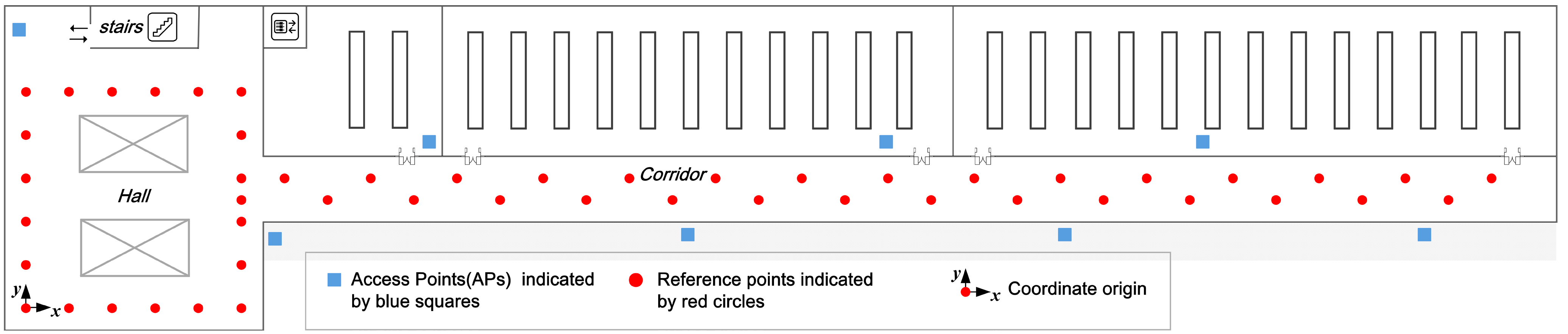
4.1. Experimental Setup

Experiments were carried out in a 43.5 m × 11.2 m indoor office area, part of the second floor of our department, as seen in Figure 4. The ground is laid with square floor tiles, whose sizes are 0.6 m × 0.6 m. We deploy a Huawei Mate smartphone running the Android 4.1 operation system as the experimental device. For the WiFi localization system, there are total 8 APs (indicated by blue squares) available and 50 reference points (indicated by red circles) deployed. The distance between neighbor reference points in the hall and corridor are 1.2 m and 1.34 m, which is the length and diagonal distance of two floor tiles, respectively. During offline phase, we collected 100 RSS training samples per reference point to build the radio map. During online phase, the user collected real time RSS vectors at about 2 Hz sampling rate. We define the reference point in the lower-left corner as the coordinate origin; the x-axis points to the right, being parallel to the corridor, and the y-axis points upward. The proposed fusion approach is compared with individual approaches of WiFi localization and PDR, the particle filter [19] using 1000 particles. To test the effectiveness of the proposed KDE based WiFi localization, we develop and test an improved particle filter (PF). Compared with the particle filter in [19], the only difference of the improved one is the particle weight update scheme, which is achieved by computing the Gaussian kernel function between the location of particles and WiFi localization results. As shown in Equations (26) and (27), the WiFi localization results are obtained by deploying KDE, while the kernel width of the Gaussian kernel function is adaptively adjusted by the related covariance. For the PDR system, we use the gyroscope module and accelerometer module built in the Huawei Mate smartphone to track the user. The gyroscope and accelerometer sensing rates are set to 100 Hz and 50 Hz, respectively. To make the gyroscope output more precise and robust, we do the necessary calibration process before carrying out experiments. Note that we only consider the common hand-held situation, and assume that the misalignment angle between the device forward and user heading is zero. The other situations, such as when the smartphone is put in a pocket or a bag, will be considered in our future works. As in much of the literature [11,16], we assume that the user’s initial location and orientation is known as a priori. To label the ground truth, we place some tags on the ground and apply a camera to record the entire walking process. Then, we manually label the coordinates of each step carefully. The localization error is calculated as the Euclidean distance between the estimated coordinates per step and the labeled coordinates per step along the true path.
Figure 4. Experimental environment includes a hall and a long corridor.
Micromachines 06 00523 g004

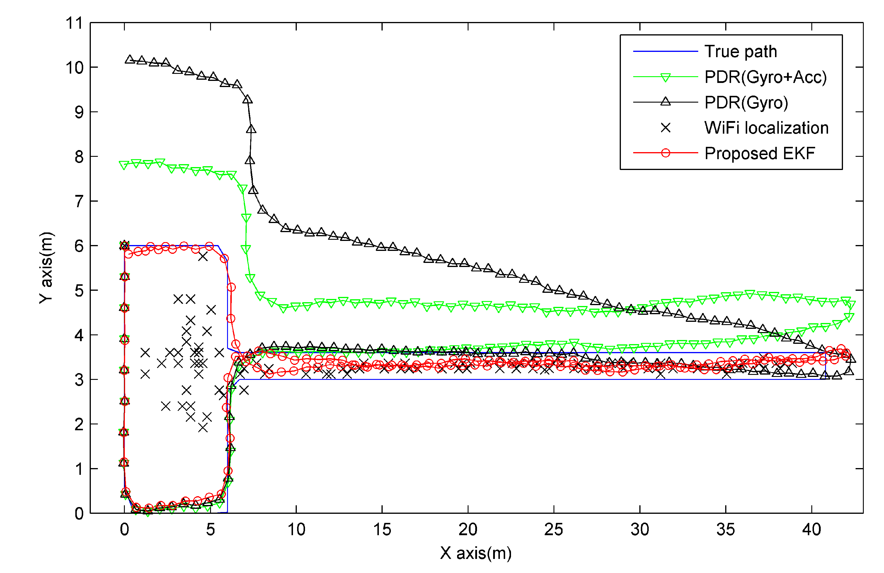
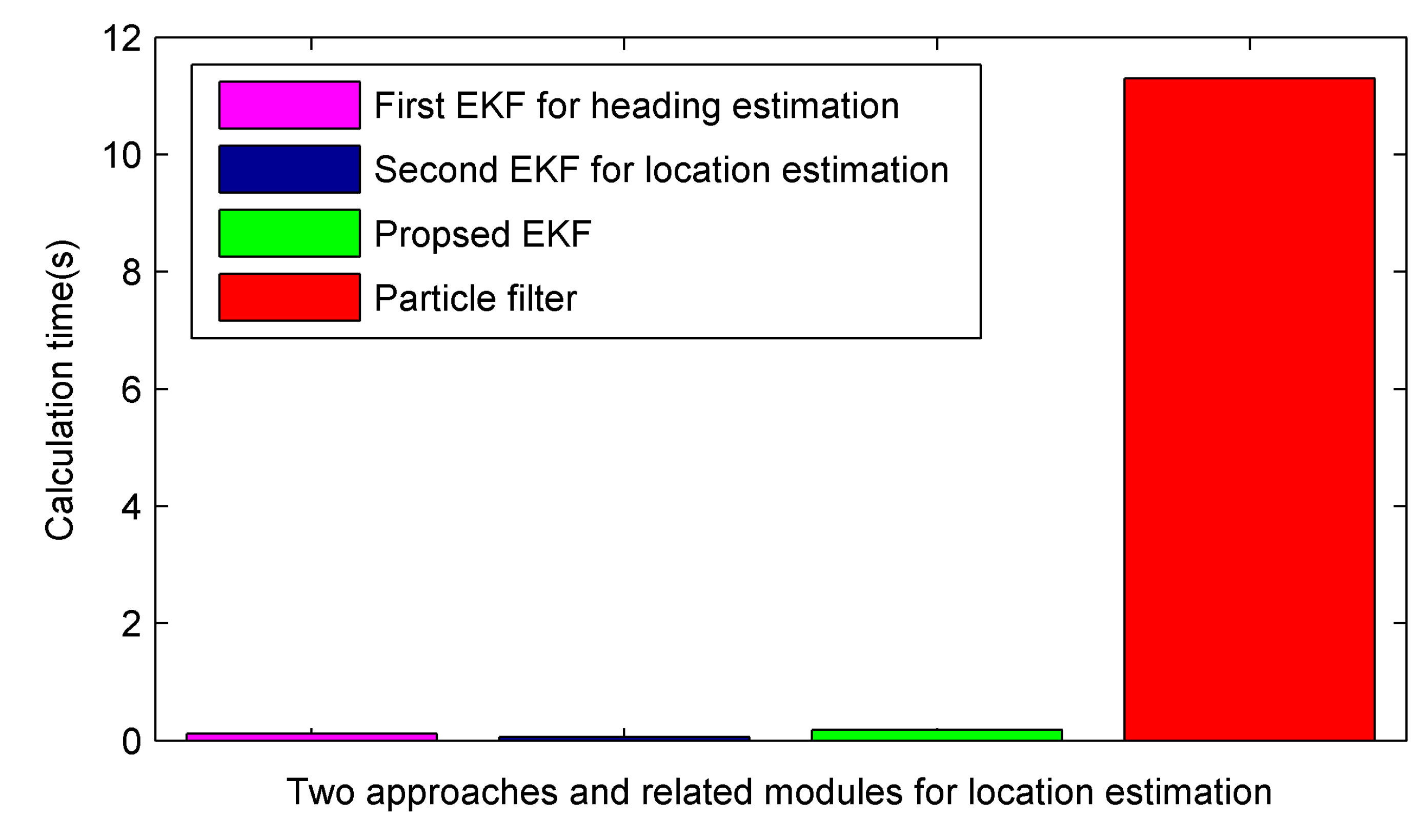
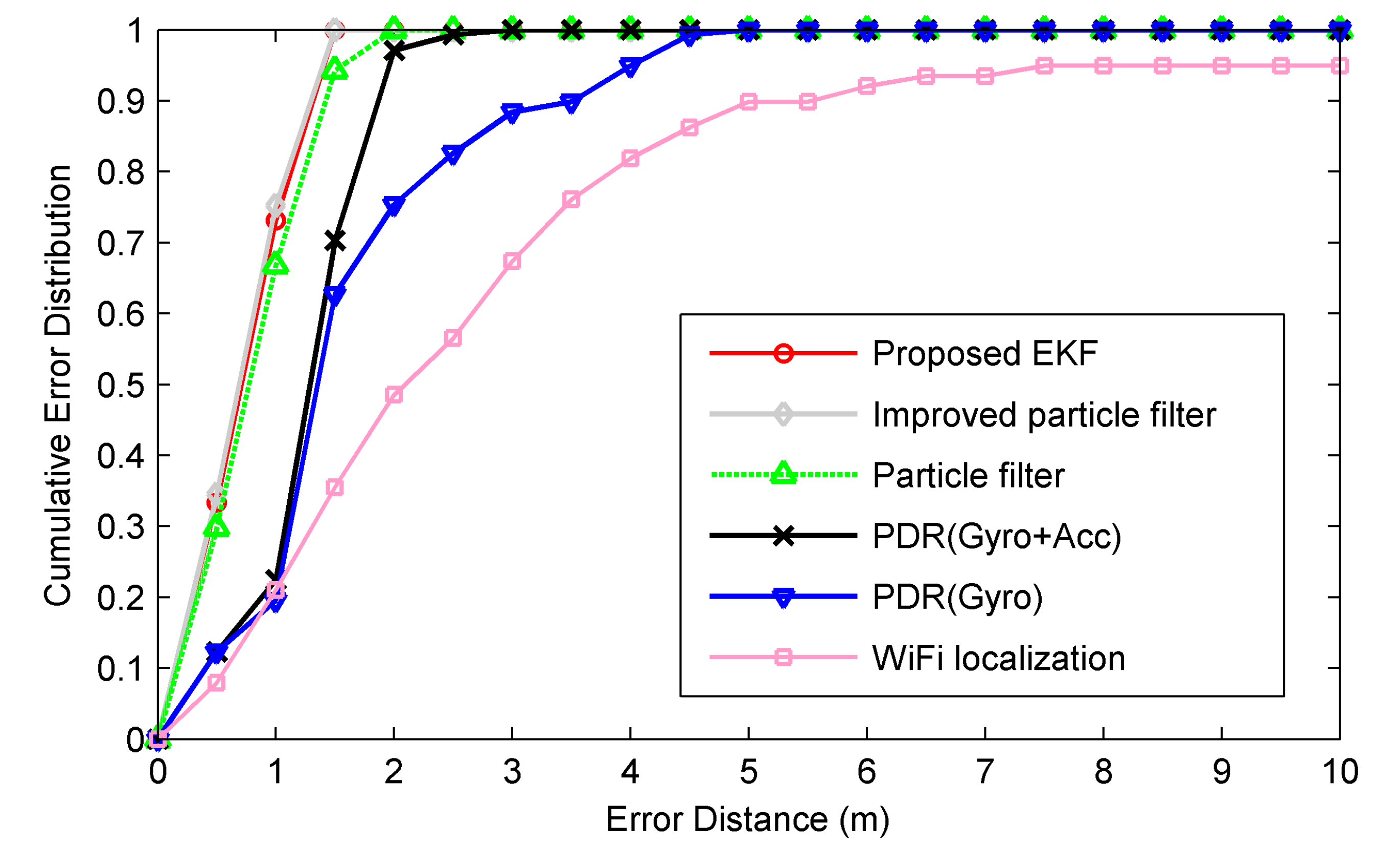
4.2. Performance Analysis

First, since the tracking performance is greatly affected by the heading estimation bias, we evaluate the heading estimation performance of the developed PDR system. Figure 5 shows the true path of the user. According to the different user heading, the whole path is divided into seven sub-paths. Figure 6 compares the heading estimation performance between approaches using gyroscope only (Gyro) and combining gyroscope with accelerometer (Gyro + Acc). One can clearly see that the estimated user headings of both approaches are close to the ground truth. Particularly, from path 1 to path 4, both approaches have approximate estimated user heading. However, from path 5 to path 7, the Gyro + Acc approach obtains better heading estimation performance than Gyro approach. The Gyro approach assumes the initial inclination angle of the hand-held smartphone is known and remains stable along the walking path. This assumption may be corrupted temporarily when drastic body swinging happens. In contrast, the EKF based Gyro + Acc approach may fuse the acceleration information well, which contains real time tilt angle information, and thus may decrease the negative effect caused by drastic body swinging.
Figure 5. True path in the experimental environment.
Micromachines 06 00523 g005
Figure 6. Yaw angle estimation performance comparison between approaches using gyroscope only and combining gyroscope with accelerometer.
Micromachines 06 00523 g006
Secondly, we compare the tracking performance between the proposed approach and the individual approaches of WiFi localization and PDR. Figure 7 shows the trajectories of the true path, PDR (Gyro), PDR (Gyro + Acc), WiFi localization and the proposed approach. PDR has comparable tracking accuracy with the proposed approach from path 1 to path 3, while it performs progressively worse with the tracking error accumulated. Particularly, from path 5 to path 7, PDR (Gyro + Acc) performs better than PDR (Gyro), since the former has a smaller heading estimation error than the latter, as can be seen in Figure 6. Though WiFi localization obtains inaccurate tracking results along the whole path, it also provides useful localization information, especially along path 4 and path 5, whose y-axis coordinates are restricted into a small region. Clearly, the proposed approach, whose estimated trajectories match the ground truth closest, performs best. This may be contributed to the effective corrections of the drift errors of PDR by fusing WiFi localization.
Figure 7. Comparisons between the true path, trajectories of PDR using gyroscope only, PDR with Gyro + Acc, WiFi localization and the proposed EKF based fusion approach.
Micromachines 06 00523 g007
Thirdly, we compare the localization accuracy between various approaches. As seen in Table 1, compared with PDR (Gyro), PDR (Gyro + Acc), WiFi localization and the particle filter, the proposed EKF reduces mean localization errors by 54.5% (0.85 m), 42.7% (0.53 m), 74.9% (2.12 m), and 12.3% (0.10 m), while it reduces standard deviations by 65.4% (0.70 m), 30.2% (0.16 m), 86.7% (2.42 m), and 7.5% (0.03 m), respectively. Compared with the improved particle filter, little performance degradation is achieved by the proposed EKF. The corresponding cumulative error distributions are shown in Figure 8. Clearly, the proposed EKF performs much better than the individual approaches, while it achieves comparable accuracy with that of the two particle filter based approaches. Particularly, the particle filter performs a little worse than both the improved particle filter and the proposed EKF, since its particle weight update scheme may incur the adverse effect caused by some RSS observations with severe fluctuations. In contrast, the improved particle filter and the proposed EKF may mitigate the adverse effect by giving a smaller weight to the noisy RSS observation, which renders a larger WiFi localization error covariance. The related error covariance may be adaptively estimated by deploying KDE during particle weight update or EKF filtering process.
Finally, we compare the calculation time of the location estimation per step between a particle filter and the proposed EKF, as shown in Figure 9. The calculation time is obtained by running the compared approaches in Matlab and averaging calculation time per step of ten traces along the true path. The calculation time required by the proposed EKF takes 0.185 s. It is mainly caused by two modules: first EKF for heading estimation takes 0.119 s; and second EKF for location estimation takes 0.064 s. The calculation time for step detection and step length estimation only takes 0.002 s. For a particle filter with 1000 particles, it takes 11.3 s and thus is unsuitable for real time applications. The proposed EKF based fusion approach greatly reduces calculation time in comparison to the particle filter in two ways. First, except for computing Jacobian matrix, EKF requires the same computation cost as that of a Kalman filter, while the particle filter needs to calculate and update the states of a great number of particles whenever implementing a new location estimation. Secondly, the computation cost for measurement update is reduced significantly by a spatial filtering process, which reduces the number of reference points involved in Equations (36) and (37). In summary, the proposed approach achieves comparable accuracy performance to that of a particle filter, while maintaining a low computation cost comparable to that of a Kalman filter. It is more suitable than the particle filter for real time indoor localization on resource-limited smartphones.
Table 1. Comparisons of mean localization errors (m) and standard deviations (m).
Compared ApproachProposed EKFPDR (Gyro + Acc)PDR (Gyro)WiFi LocalizationParticle FilterImproved PF
Mean error0.711.241.562.830.810.65
Standard deviation0.370.531.072.790.400.33
Figure 8. Accuracy comparisons between the proposed EKF based fusion approach, improved particle filter, particle filter, PDR with Gyro + Acc, PDR using gyroscope only and WiFi localization.
Micromachines 06 00523 g008
Figure 9. Comparisons of the calculation time for location estimation per step between a particle filter and the proposed EKF based approach, whose two main modules are: first EKF for heading estimation; and second EKF for location estimation.
Micromachines 06 00523 g009

5. Conclusions and Future Work

The main contributions of this work are three-fold. First, we design a novel data fusion framework for combing PDR and WiFi localization by using an extended Kalman filter. The proposed fusion approach reduces mean localization errors by 42.7% and 74.9% as compared to using PDR and WiFi localization alone, respectively. Compared with a particle filter, the comparable accuracy is achieved, while the computation cost is reduced greatly.
Secondly, to adapt the unknown measurement equation and related noise statistics, we propose a RSS-location measurement model by using KDE. Unlike previous approaches setting measurement noise covariance manually, we adaptively and accurately estimate it by approximating the probability density using KDE. In addition, a spatial filtering process is combined to reduce the computation cost by restricting localization into a vicinity of the localization result of previous step.
Finally, we develop a quaternion based heading estimation method by using another EKF to fuse gyroscopes and accelerometers. Instead of using the most widely used Euler angles and DCM based orientation descriptors, we use the quaternion descriptor, since it can both avoid the singularity problems and require the least computations simultaneously.
In future works, we will further expand the proposed approach to the situation when the placement of a smartphone is unconstrained, such as in a pocket or a handbag. This situation has been paid little attention, and may present critical challenges for heading estimation in PDR systems. In addition, building maps and related landmarks will also be combined to correct the heading estimations and improve the localization accuracy.

Acknowledgments

This research is supported by National Natural Science Foundation of China (Granted Nos. 61301132, 61300188, and 61301131) and the Fundamental Research Funds for the Central Universities (Granted No. 3132014211).

Author Contributions

Zhi-An Deng proposed the original idea and wrote this paper; Ying Hu analyzed the data and gave some valuable suggestions; Zhi-An Deng and Jianguo Yu developed the heading estimation algorithm based on the first EKF; Zhenyu Na designed the experiments and revised the paper.

Conflicts of Interest

The authors declare no conflict of interest.

References

  1. Petrova, K.; Wang, B. Location-based services deployment and demand: A roadmap model. Electron. Commer. Res. 2011, 11, 5–29. [Google Scholar] [CrossRef]
  2. Gu, Y.Y.; Lo, A.; Niemegeers, I. A survey of indoor positioning systems for wireless personal networks. IEEE Commun. Surv. Tutor. 2009, 11, 13–32. [Google Scholar] [CrossRef]
  3. Gezici, S.; Tian, Z.; Giannakis, G.B.; Kobayashi, H.; Molisch, A.F.; Poor, H.V.; Sahinoglu, Z. Localization via ultra-wideband radios: A look at positioning aspects for future sensor networks. IEEE Signal Proc. Mag. 2005, 22, 70–84. [Google Scholar] [CrossRef]
  4. Ni, L.M.; Liu, Y.; Lau, Y.C.; Patil, A.P. LANDMARC: Indoor location sensing using active RFID. Wirel. Netw. 2004, 10, 701–710. [Google Scholar] [CrossRef]
  5. Colombo, A.; Fontanelli, D.; Macii, D.; Palopoli, L. Flexible indoor localization and tracking based on a wearable platform and sensor data fusion. IEEE Trans. Instrum. Meas. 2014, 63, 864–876. [Google Scholar] [CrossRef]
  6. Zhou, M.; Xu, Y.B.; Tang, L. Multilayer ANN indoor location system with area division in WLAN environment. J. Syst. Eng. Electron. 2010, 21, 914–926. [Google Scholar] [CrossRef]
  7. Ma, L.; Xu, Y.B. Received signal strength recovery in green WLAN indoor positioning system using singular value thresholding. Sensors 2015, 15, 1292–1311. [Google Scholar] [CrossRef] [PubMed]
  8. Deng, Z.A; Xu, Y.B.; Ma, L. Indoor positioning via nonlinear discriminative feature extraction in wireless local area network. Comput. Commun. 2012, 35, 738–747. [Google Scholar] [CrossRef]
  9. Feng, C.; Au, W.S.A.; Valaee, S.; Tan, Z. Received-signal-strength-based indoor positioning using compressive sensing. IEEE Trans. Mob. Comput. 2012, 11, 1983–1993. [Google Scholar] [CrossRef]
  10. Oliver, W.; Robert, H. RF-based initialisation for inertial pedestrian tracking. In Proceedings of 7th International Conference, Pervasive 2009, Nara, Japan, 11–14 May 2009; pp. 238–255.
  11. Li, F.; Zhao, C.; Ding, G.; Gong, J.; Liu, C.; Zhao, F. A reliable and accurate indoor localization method using phone inertial sensors. In Proceedings of 14th ACM International Conference on Ubiquitous Computing, Pittsburgh, PA, USA, 5–8 September 2012; pp. 1–10.
  12. Tian, Z.; Zhang, Y.; Zhou, M.; Liu, Y. Pedestrian dead reckoning for MARG navigation using a smartphone. EURASIP J. Adv. Sign. Process. 2014, 65, 1–9. [Google Scholar]
  13. Wang, H.; Lenz, H.; Szabo, A.; Bamberger, J.; Hanebeck, U.D. WLAN-based pedestrian tracking using particle filters and low-cost MEMS sensors. In Proceedings of the 2007 4th Workshop on Positioning, Navigation and Communication (WPNC’07), Hannover, Germany, 22–22 March 2007; pp. 1–7.
  14. Ruiz, A.R.J.; Granja, F.S.; Honorato, J.C.P.; Rosas, J.I.G. Accurate pedestrian indoor navigation by tightly coupling foot-mounted IMU and RFID measurements. IEEE Trans. Instrum. Meas. 2012, 61, 178–189. [Google Scholar] [CrossRef]
  15. Tarrío, P.; Besada, J.A.; Casar, J.R. Fusion of RSS and inertial measurements for calibration-free indoor pedestrian tracking. In Proceedings of the 2013 16th International Conference on Information Fusion (FUSION), Istanbul, Turkey, 9–12 July 2013; pp. 1458–1464.
  16. Kim, Y.; Chon, Y.; Cha, H. Smartphone-based collaborative and autonomous radio fingerprinting. IEEE Trans. Syst. Man and Cybern. C Appl. Rev. 2012, 42, 112–122. [Google Scholar] [CrossRef]
  17. Tian, Z.; Fang, X.; Zhou, M.; Li, L. Smartphone-Based Indoor Integrated WiFi/MEMS Positioning Algorithm in a Multi-Floor Environment. Micromachines 2015, 6, 347–363. [Google Scholar] [CrossRef]
  18. Evennou, F.; Marx, F. Advanced integration of WiFi and inertial navigation systems for indoor mobile positioning. Eurasip J. Appl. Signal Proc. 2006, 1–11. [Google Scholar] [CrossRef]
  19. Wu, D.; Xia, L.; Mok, E. Hybrid location estimation by fusing WLAN signals and inertial Data. In Principle and Application Progress in Location-Based Services; Lecture Notes in Geoinformation and Cartography, Liu, C., Eds.; Springer: Berlin, Germany, 2013; pp. 81–92. [Google Scholar]
  20. Rai, A.; Chintalapudi, K.K.; Padmanabhan, V. N.; Sen, R. Zee: Zero-effort crowdsourcing for indoor localization. In Proceedings of the 18th Annual International Conference on Mobile Computing and Networking Istanbul, Turkey, 22–26 August 2012; pp. 293–304.
  21. Masiero, A.; Guarnieri, A.; Pirotti, F.; Vettore, A. A Particle Filter for Smartphone-Based Indoor Pedestrian Navigation. Micromachines 2014, 5, 1012–1033. [Google Scholar] [CrossRef]
  22. Chen, Z.; Zou, H.; Jiang, H.; Zhu, Q.; Soh, Y.C.; Xie, L. Fusion of WiFi, smartphone sensors and landmarks using the Kalman filter for indoor localization. Sensors 2015, 15, 715–732. [Google Scholar] [CrossRef] [PubMed]
  23. Sun, Y.; Xu, Y.; Li, C.; Ma, L. Kalman/Map Filtering-Aided Fast Normalized Cross Correlation-Based Wi-Fi Fingerprinting Location Sensing. Sensors 2013, 13, 15513–15531. [Google Scholar] [CrossRef] [PubMed]
  24. Youssef, M.; Agrawala, A. The Horus WLAN location determination system. In Proceedings of the IEEE Third International Conference on Mobile Systems, Applications, and Services, Seattle, WA, USA, 6–8 June 2005; pp. 205–218.
  25. Afzal, M.H.; Renaudin, V.; Lachapelle, G. Use of earth’s magnetic field for mitigating gyroscope errors regardless of magnetic perturbation. Sensors 2011, 11, 11390–11414. [Google Scholar] [CrossRef] [PubMed]
  26. Afzal, M.H.; Renaudin, V.; Lachapelle, G. Assessment of indoor magnetic field anomalies using multiple magnetometers. In Proceedings of the 23rd International Technical Meeting of The Satellite Division of the Institute of Navigation (ION GNSS 2010), Portland, OR, USA, 21–24 September 2010; pp. 1–9.
  27. Wang, H.; Sen, S.; Elgohary, A.; Farid, M.; Youssef, M.; Choudhury, R.R. No need to war-drive: unsupervised indoor localization. In Proceedings of the 10th International Conference on Mobile Systems, Applications, and Services (MobiSys’12), Low Wood Bay, Lake District, UK, 25–29 June 2012; pp. 197–210.
  28. Chen, L.H.; Wu, E.H.K.; Jin, M.H.; Chen, G.H. Intelligent fusion of Wi-Fi and inertial sensor-based positioning systems for indoor pedestrian navigation. IEEE Sens. J. 2014, 14, 4034–4042. [Google Scholar] [CrossRef]
  29. Sabatini, A. M. Quaternion-based extended Kalman filter for determining orientation by inertial and magnetic sensing. IEEE Trans. Biomed. Eng. 2006, 53, 1346–1356. [Google Scholar] [CrossRef] [PubMed]
  30. Sabatini, A.M.; Martelloni, C.; Scapellato, S.; Cavallo, F. Assessment of walking features from foot inertial sensing. IEEE Trans. Biomed. Eng. 2005, 52, 486–494. [Google Scholar] [CrossRef] [PubMed] [Green Version]
  31. Premerlani, W.; Bizard, P.; Premerlani, W.; Bizard, P. Direction cosine matrix IMU: Theory. Available online: http://gentlenav.googlecode.com/files/DCMDraft2.pdf (accessed on 21 April 2015).
  32. Chou, J.C.K. Quaternion kinematic and dynamic differential equations. IEEE Trans. Robot. Autom. 1992, 8, 53–64. [Google Scholar] [CrossRef]
  33. Cenedese, A.; Ortolan, G.; Bertinato, M. Low-density wireless sensor networks for localization and tracking in critical environments. IEEE Trans. Veh. Technol. 2010, 59, 2951–2962. [Google Scholar] [CrossRef]
  34. Scott, D.W. Multivariate Density Estimation; Wiley: Hoboken, NJ, USA, 1992. [Google Scholar]
  35. Jahn, J.; Batzer, U.; Seitz, J.; Patino-Studencka, L.; Boronat, J.G. Comparison and evaluation of acceleration based step length estimators for handheld devices. In Proceedings of 2010 International Conference on Indoor Positioning and Indoor Navigation (IPIN), Zurich, Switzerland, 15–17 September 2010; pp. 1–6.
  36. Zhang, R.; Bannoura, A.; Hoflinger, F.; Reindl, L.M.; Schindelhauer, C. Indoor localization using a smart phone. In Proceedings of 2013 IEEE Sensors Applications Symposium (SAS), The San Luis Resort Galveston, TX, USA, 19–21 February 2013; pp. 38–42.
  37. Bar-Shalom, Y.; Li, X.-R.; Kirubarajan, T. Estimation with Applications to Tracking and Navigation; Wiley: New York, NY, USA, 2001. [Google Scholar]

