Article

A Disposable Dispensing Valve for Non-Contact Microliter Applications in a 96-Well Plate Format †

1
Laboratory for MEMS Applications, IMTEK-Department of Microsystems Engineering, University of Freiburg, Georges-Koehler-Allee 103, 79110 Freiburg, Germany
2
BioFluidix GmbH, Georges-Koehler-Allee 103, 79110 Freiburg, Germany
*
Author to whom correspondence should be addressed.
This paper is an extended version of our paper published in the 2nd International Conference on Microfluidic Handling Systems, Freiburg, Germany, 8–10 October 2014.
Micromachines 2015, 6(4), 423-436; https://doi.org/10.3390/mi6040423
Submission received: 27 February 2015 / Revised: 30 March 2015 / Accepted: 30 March 2015 / Published: 3 April 2015

Abstract

:
We present a miniaturized, disposable, normally-closed electromagnetic dispensing valve for the microliter range to process 96-well plates. The novel injection-molded valve is designed to fit into a 9 mm grid to realize an eight channel dispensing head, enabling the serial processing of well plates row-by-row. The presented dispensing valve design originates from a miniaturization study of a previously developed functional model. The outer diameter of the valve, including all actuating components, was reduced by 8 mm to an overall diameter of 8.5 mm without compromising the performance. Additionally, the actuation current of the valve could be reduced to 5 A. The valve is characterized for a volume range between 840 nL and 5.3 μL. The performance of the injection molded valve is competitive to commercially available dispensing valves, featuring the advantages of low fabrication costs, disposability, low mounting size, easy handling, and super silent actuation.

1. Introduction

The requirements on the dispensing performance of liquid handling systems in terms of precision, trueness and costs are increasingly growing. Additionally, the risk of cross-contamination and the need of expensive cleaning steps are omnipresent issues [1]. Therefore, non-contact dispensing technologies [2,3,4] based on disposable components will be used preferably in fields applying many different biological sample solutions and where cross-contamination needs to be eliminated, e.g., assay development, immunochemistry, or drug discovery.
In a previous work [5], we developed a disposable, normally-closed, non-contact dispensing valve considering technical specifications provided by industry and researchers [6]. The valve consists of an external coil, a ferromagnetic plunger with a sealing layer on the bottom, an external normally-closed (NC) magnet, and a nozzle. The working principle is shown in Figure 1. In its initial, normally-closed state, the plunger is in contact with the valve seat formed by the rear end of a nozzle due to the attracting force FRingMagnet between the plunger (permanent rod magnet made of Neodymium-Iron-Boron (NdFeB)) and the NC magnet (hard ferrite ring magnet). The movement of the plunger is driven by an electrical current pulse through the coil inducing a magnetic field forcing the plunger to move up (Fcoil). After a certain actuation time, the current is turned off and the valve is closed again (FRingMagnet). The dispensed volume can be controlled by several parameters. In addition to the duration of the actuation pulse, which defines the dispensed volume for a certain flowrate over time, the flow rate can also be adjusted by either varying the applied external actuating pressure or the nozzle dimensions in length and inner diameter.
Figure 1. Working principle of the normally-closed, electromagnetic dispensing valve. In its initial state (a), the magnetic plunger is attracted by the normally-closed (NC) magnet. The valve is sealed by a thin silicone layer at the bottom of the plunger which is in contact with the sharp-edged nozzle. A current Iactuating will generate a magnetic field forcing the plunger to move up (b). After a defined actuation time, the current Iactuating is turned off and the valve is closed by the attracting force of the NC magnet (c).
Micromachines 06 00423 g001
The major issues of the functional model described in [5] were the large outer diameter of 16.5 mm including actuation coil, the heat coupling into the fluid induced by the required high actuation currents and the large fabrication tolerances of the used steel nozzles, which led to high tip-to-tip variation described in terms of the coefficient of variation (CV) between different tips. Therefore, the tip-to-tip CV has been further improved by using nozzles made from polyimide featuring smaller fabrication tolerances. In addition, by reducing the outer diameter of the valve down to 8.5 mm, one is able to process 96-well plates with an 8-channel dispensing head row by row, which will increase the throughput thus reducing analysis costs. Additionally, the heat induced by the high actuating current in the previous functional model led to a degraded performance that had to be improved: The heat produced by the actuating current inside the coil is coupled into the liquid and typically reduces the viscosity of the liquid. This leads to changes in the flowrate, and, thus, the precision of the dispensed volume over time is compromised. Therefore, the actuating current had to be lowered by the miniaturized design from 10 A, previously, down to 5 A for the presented valve.

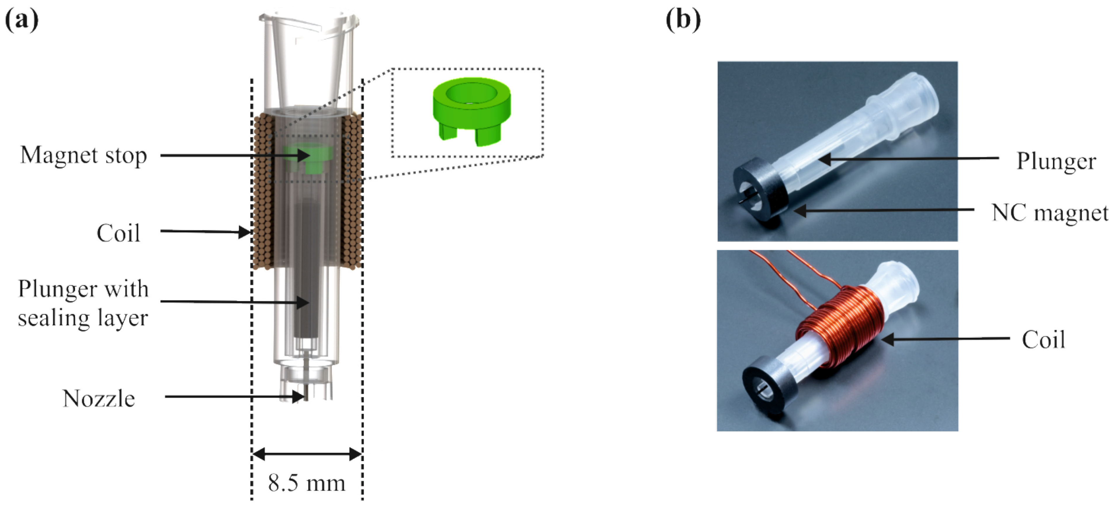
2. Miniaturization Process

In this chapter, we consider the main forces acting on the plunger in order to identify design rules to reduce the outer diameter of the valve, from 16.5 down to 8.5 mm, while maintaining high opening forces of the plunger and minimize the induced heat.

2.1. Main Acting Forces

The miniaturization study is based on the theoretical consideration of three general forces acting on the ferromagnetic plunger during actuation and are described in detail elsewhere [7,8]. These forces are: (a) the force between the coil and the plunger Fplunger, which is responsible for opening the valve, (b) the force between the normally-closed (NC) ring magnet and the plunger FRingMagnet, attracting the plunger to close the valve, and (c) the pressure force Fpressure(open), as illustrated in Figure 2.
Figure 2. Cross section of the disposable, electromagnetic dispensing valve and the three main forces acting on the ferromagnetic plunger.
Micromachines 06 00423 g002

2.2. Force between Two Permanent Magnets

The force FRingMagnet between the permanent ring magnet (NC ring magnet) and the permanent cylindrical magnet (plunger), both with axial magnetization is calculated using Equation (2) in [7]. Due to the constant magnetization of the plunger and the NC ring magnet, the Coulombian model of a permanent magnet is applied, thus, each magnet can be described by two charged planes located at their upper and lower surface. FRingMagnet depends mainly on the dimensions of the magnets and their magnetization.
Using a hard ferrite as an NC ring magnet, with an inner diameter of 4 mm, an outer diameter of 8 mm, and a height of 3 mm, as well as a solid NdFeB magnet as plunger, with an outer diameter of 2 mm and a height of 10 mm, leads to a maximum calculated force FRingMagnet of 30.11 mN at a distance of 2 mm between the lower surface of the plunger and the upper surface of the NC magnet. Figure 3b compares the calculated force with the measured force between the two magnets in dependency of the described distance.
The force is measured with a piezoelectric force sensor (shown in Figure 3a). Therefore, the magnetic plunger is aligned concentrically above the inner hole of the NC ring magnet whereby the lower side of the plunger is facing the upper side of the NC magnet. The NC magnet is fixed and in contact with the force sensor. The plunger is moved up and down in 1 mm steps to vary the distance d between the magnets. One can see a good correlation between the calculated and measured curve, which confirms the applicability of the used formula (Equation (2) in Reference [7]).
Figure 3. (a) Schematic set-up for measuring the force FRingMagnet between a ferromagnetic plunger and a ring magnet. Here, the ring magnet is in contact with a piezoelectric force sensor. The plunger is placed concentrically above it and can be vertically moved up and down, which will change the distance d. In (b) the comparison between the measured (red) and calculated (black) force FRingMagnet according to Equation (2) in Reference [7] is shown.
Micromachines 06 00423 g003

2.3. Pressure Force

A second force acting on the plunger is the pressure force appearing from the external actuating pressure in the liquid. The resulting pressure force depends on the surface ratio, which is directly affected by the pressure. We consider all areas off the magnet that are exposed to the actuating pressure. After adding these forces, one gets the resulting pressure force acting on the cross section of the outer diameter of the nozzle in direction of the external applied pressure:
F pressure(open) = p ext π r nozzle 2

2.4. Interactive Force between Coil and Plunger

In order to miniaturize the valve, we have to reduce the size of the coil on the one hand and achieve an opening force FPlunger high enough to actuate the valve on the other. A detailed calculation of the force FPlunger between a coil and a permanent magnet can be found in [8]. The opening force FPlunger is dependent on the coil dimensions, the current, the distance between the coil and the plunger, and the plunger properties and dimensions. The force between the plunger and the coil is linearly dependent on the current, the magnetization, and the windings. By increasing the radius of the plunger, FPlunger increases with the square. The opening force also strongly depends on the distance between the coil and the plunger, and by decreasing the radius of the coil at constant windings, length, and outer diameter, FPlunger increases with the square.
In addition to achieving a high enough opening force, we also want to minimize the Joule or ohmic heating, which occurs in every conductor [9]. Thereby, the electric energy is converted into thermal energy. It is an irreversible process and the thermal energy produced can thereby be calculated with the following formula [9]:
  W = I 2 R t = I 2 ρ e L A
where I is the current in A, ρe is the electric resistivty in Ωm, L is the length of the conductor in m, A is the cross-section of the wire in m and t the duration of the current pulse in s.
An omnipresent risk is that the Joule heating of the coil might be coupled into the liquid, thus reducing the viscosity of the fluid inside the valve. A reduced viscosity implies changes in the flowrate at constant driving pressure conditions, which leads to increased dispensed volumes over time. To minimize the risk, the Joule heating has to be reduced by increasing the wire diameter and reducing the windings and current. However, by reducing the current and the windings, one will decrease the opening force FPlunger. Therefore, the trade-off between reducing the Joule heating and achieving a proper opening force, which is high enough to actuate the valve, has to be found.
To calculate the required opening force according to Equation (11) in [8], a NdFeB magnet was used as plunger (OD = 2 mm, L = 10 mm), whereas the target actuation current was assumed to be not higher than a maximum of 5 A to reduce Joule heating. A pressure of 2 bar was specified to be the maximum applicable actuating pressure and the outer diameter of the nozzle was fixed at 355.4 μm, which corresponds to the dimensions of the available polyimide tube material. The required opening force FPlunger to guarantee a reliable functionality of the valve for the entire actuation pressure range can therefore be calculated by:
FPlunger > FRingMagnet + Fpressure(open) > 30.11 mN + 19.8 mN = 49.91 mN
As a further condition, the outer diameter of the coil was set to 8.5 mm. Based on these theoretical considerations, the design rules for the valve miniaturization could be identified and are listed in Table 1. The selected configuration for the miniaturized design entails a maximum opening force of FPlunger of 89.15 mN (Equation (11) in [8]), which guarantees a reliable opening of the valve up to 2 bar.
To depict the reduced Joule heating for the miniaturized coil design, we measured the temperature at the coil with a PT100 and compare it with the heat induced in the prior coil design (see Figure 4). Both coil dimensions are listed in Table 1. The actuation time is set to 250 ms and the current to 8 and 5 A, respectively. The pause between the current pulses was set to 16 s.
Table 1. Comparison of the dimensions of the prior functional model [5] and the miniaturized design of the disposable, electromagnetic dispensing valve.
DimensionsPrior functional model [5]Miniaturized design
Coil outer diameter16.5 mm8.5 mm
Coil inner diameter9 mm5.5 mm
Coil length8.5. mm12 mm
Number of windings10572
Required peak current8 A5 A
Overall valve length27.1 mm29.35 mm
Figure 4. Comparison of the induced heat in the prior and the miniaturized coil design. Temperature of the coil is measured after every actuation pulse. The pause between the actuation pulses was set to 16 s. The actuation current was set to 8 and 5 A (black) for the prior design and 5 A (red) for the new miniaturized design.
Micromachines 06 00423 g004
The prior functional model had a required minimal peak current of 8 A. After 24 dispenses we measured a temperature increase of the coil of 4.2 °C (see Figure 4). In the worst case, if the complete temperature increase would be coupled to the fluid, for example, for water the viscosity would be reduced from 0.93 to 0.85 mPas. This would increase the flow rate by 21% (see Equation (5)) over time, and could reduce the precision of the valve. For the miniaturized coil design, which needs a minimal peak current of 5 A, we detected a temperature increase of 1.2 °C, changing the viscosity of water in the worst case from 0.94 to 0.91 mPas, thus, reducing the maximal increase of the flow rate inside the valve down to 3%.

3. Fabrication Process

Based on the design parameters presented in Table 1, the entire valve design is adapted to the fabrication by an injection molding process using different medical-grade polypropylene materials (BORMED HD 850 MO, Purell RP 270 G and Purell HP 570 U provided by Braunform GmbH, Bahlingen, Germany) to implement cost effectiveness and the compatibility to medical applications. In contrast to the functional model presented in [5], the novel design consists of a one-part valve body, as given by the computer-aided design (CAD) model in Figure 5a.
As nozzle material, a polyimide (PI) capillary with an inner diameter of 223 ± 6.4 μm, an outer diameter of 355.4 ± 6.4 μm, and a length of 5.5 ± 0.5 mm, featuring very low fabrication tolerances, was used. The nozzle is inserted into the molding tool and then insert molded by polypropylene.
Figure 5. (a) CAD model of the one-part valve body with an insert molded polyimide nozzle. The plunger with a 1 mm thick silicone layer is inserted and the valve is closed with a stopper (green). (b) Photographs of the first samples of the injection molded, disposable, non-contact dispensing valve with and without coil.
Micromachines 06 00423 g005
Figure 5a shows the valve assembly consisting of the plunger, coated with Parylene C, having a thin silicone layer at the bottom, inserted in the one-part valve body and closed by a magnet stop (green). The inserted magnet stop limits the opening movement of the plunger to 2.75 mm. Furthermore, the valve body features a Luer-Lock fitting to connect to a liquid reservoir. Figure 5b shows the first samples of the injection-molded valve. The used coil for the valve characterization has an inner diameter of 5.5 mm, an outer diameter of 8.5 mm, and a length of 12 mm with 72 windings at a wire diameter of 0.45 mm.

4. Results and Discussion

In the following section, we present the characterization results of the dispensing performance of the miniaturized valve considering different actuating pressures. Furthermore, we will demonstrate the high impact of the fabrication tolerances of the nozzle on the tip-to-tip CV defined in [1].
The dispensing performance was characterized applying the gravimetric regression method (GRM). The GRM is based on a linear regression analysis of continuously monitored gravimetric results. Therefore, evaporation effects and environmental influence on the balance like vibrations, etc., are compensated and the volume at the time of dispense can be determined very precisely [10]. The experimental set-up is shown in Figure 6. The dispensing valve is connected to a pressurized reservoir. We use peak-and-hold driving electronics to control the actuation time and current of the valve. With these electronics, one is able to independently adjust the peak and the hold current. In order to open the valve, a higher peak current is needed to overcome the maximal force FRingMagnet acting in the initial state. Once the valve is fully opened, the distance between the plunger and the NC ring magnet increases from 2 to 4.75 mm, thus, reducing the acting closing force FRingMagnet from 30.11 down to 16.8 mN (cf. Figure 3b). In this state, the current through the coil can be reduced to the so-called hold current to keep the plunger at this position, which will lead to reduced power consumption and less heat coupling into the liquid.
In order to evaluate and compare the precision of the different fabricated valves, we use the coefficient of variation (CV). It describes the ratio between the standard deviation s and the mean volume V ¯ of n = 24 individual measurements following the definitions and notation given in [1].
CV intra run = s V ¯ = 1 n 1 i = 1 n ( d i V ¯ ) V ¯
where di is the volume of a single dispense in nL and n is the number of dispenses within one experimental run.
Figure 6. Measurement set-up to characterize the dosing performance of the electromagnetic valve consisting of a gravimetric balance, a dispensing valve, a pressurized reservoir, a pressure controller (not shown here), and the peak-and-hold electronics.
Micromachines 06 00423 g006

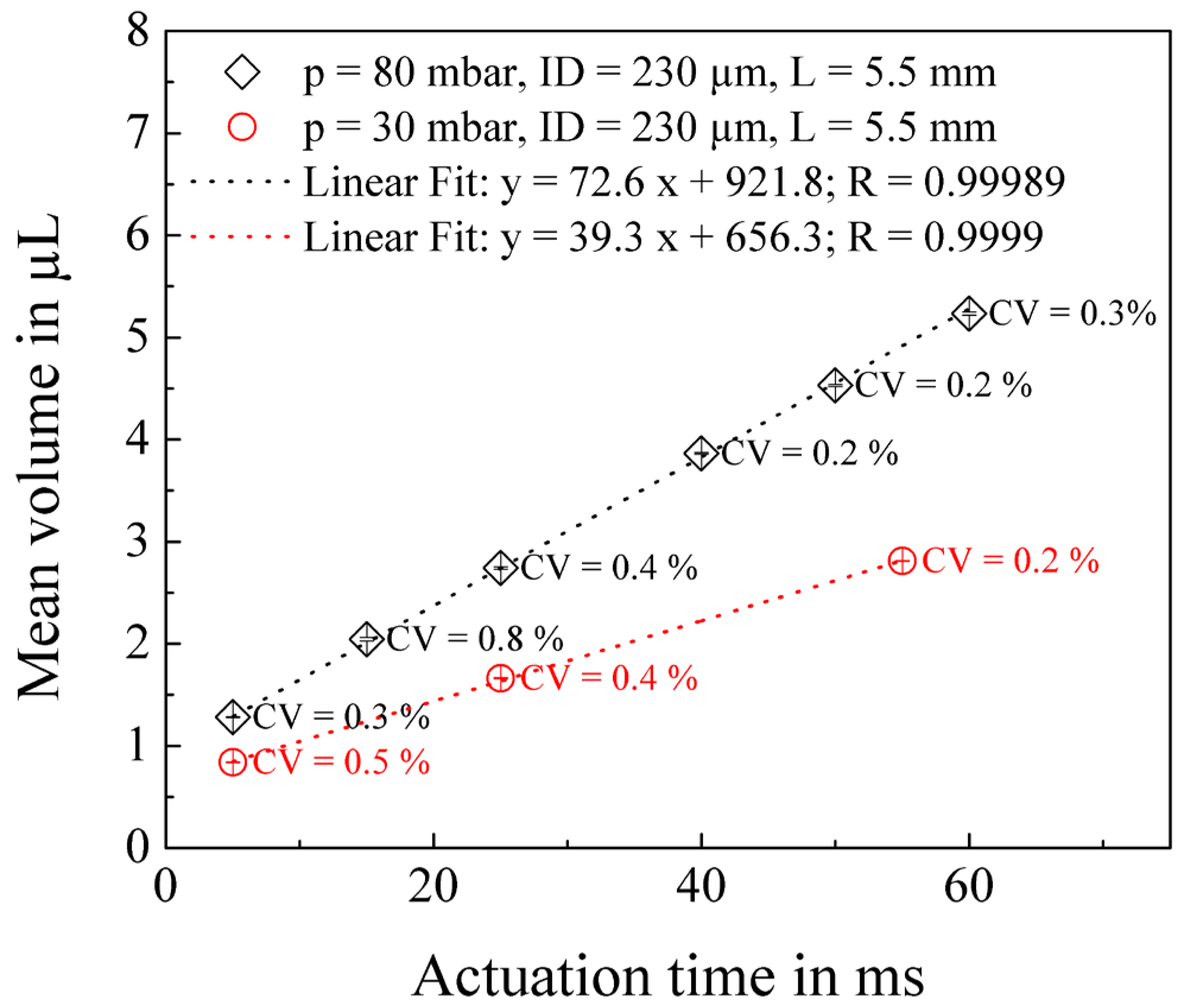
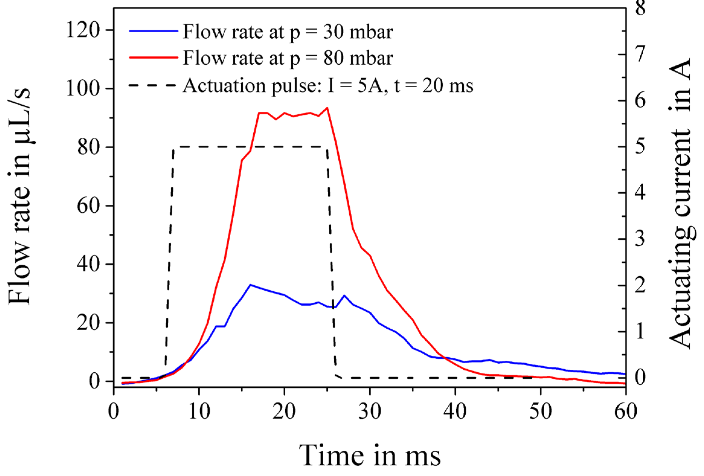
4.1. Dosing Performance at Different Actuation Pressures

To characterize the dosing performance of the injection molded valve experimentally, the amplitude of the peak pulse is set to 5 A for a duration of 5 ms, while the duration of the hold current (4 A) is varied between 0 and 55 ms. The actuating pressure is set to 30 and 80 mbar to investigate the influence of the pressure on the flow rate and the dispensed volume. The test medium is pure water. Figure 7 shows the results of this characterization. Each measurement point in the diagram states the mean volume V ¯ of one experimental run, consisting of n = 24 dispenses in combination with the corresponding intra-run CV value according to Equation (4). The very small error bars are the corresponding standard deviation s (cf. Equation (4)).
Figure 7. The dispensing performance shows a linear dependency between the actuation time and the dispensed mean volume. Each data point represents the mean volume of one run of 24 individual measurements. The percentage values state the respective CV.
Micromachines 06 00423 g007
Obviously, the valve shows an excellent precision with intra-run CVs between 0.2% and 0.8% for a volume range between 840 nL and 5.3 μL. One can see very good linear behavior in dependence of the opening time with linearity coefficients of R = 0.9999 at 30 mbar and R = 0.99989 at 80 mbar. Apparently, the amplitude of the actuating pressure also has an influence on the dispensed volume, as expected from theory, but not on the precision in the tested range. By increasing the pressure by a factor of 2.7, from 30 to 80 mbar, the dispensed volume per time was increased by a factor of 1.8. In a first order approximation, one could expect a proportional increase of the flow rate by the same factor of 2.7 under this circumstance. However, the more detailed investigation below will show how the relatively smaller increase can be explained.
Assuming that the flow rate through the valve is mainly restricted by the nozzle, which has the highest fluidic resistance of all involved components, one can approximate the fluidic resistance as follows [11]:
Q = Δ p   π   r 4 l
where Q is the flow rate in m³/s, Δp is the pressure drop over the fluidic resistance in Pa, r is the radius of the nozzle in m, η is the dynamic viscosity in Pas and l the length of the nozzle in m.
The theoretical flow rate at 20 °C according to Equation (5) for an applied pressure of 30 mbar is, thus, 33.1 μL/s and 88.3 μL/s at 80 mbar, respectively. In order to examine this experimentally, the flow profile was measured with a flow sensor (Sensirion AG, Staefa, Switzerland [12]) connected between the reservoir and the dispensing valve during operation (see Figure 8).
Figure 8. Flow profile during the dispensing for an applied actuating pressure of 30 and 80 mbar, respectively. The actuation time was set to 20 ms and the actuation current to 5 A.
Micromachines 06 00423 g008
Once the valve is completely open and a reasonably stable flow is established, the average measured flow rate amounts to 91.6 μL/s for an applied pressure of 80 mbar and 28.6 μL/s at 30 mbar, respectively. This correlates very closely with the theoretical expected values given by Equation (4). However, as depicted in Figure 8, the full flow profile is only established 10 ms after the current pulse is applied. The deviation of the dispensed volume per time from the first order approximation mentioned above can, therefore, be explained by the increasing and decreasing flow contributions before and after a stable flow through the valve is established. In particular, mechanical inertia of the plunger, fluidic inductivity of the liquid, and the electrical inductivity of the coil are responsible for this behavior outside of the steady state. Therefore, it becomes clear that no directly proportional increase in dispense volume as function of actuating pressure can be expected at constant actuation times. Furthermore, for actuation times smaller 10 ms, the linear fit, as shown in Figure 7, cannot be applied anymore to estimate the dispensed volume. For such very small actuation times, a higher decrease in the dispensed volume occurs, due to the fact that no constant flow condition is established and the opening and closing effects become pre-dominant.

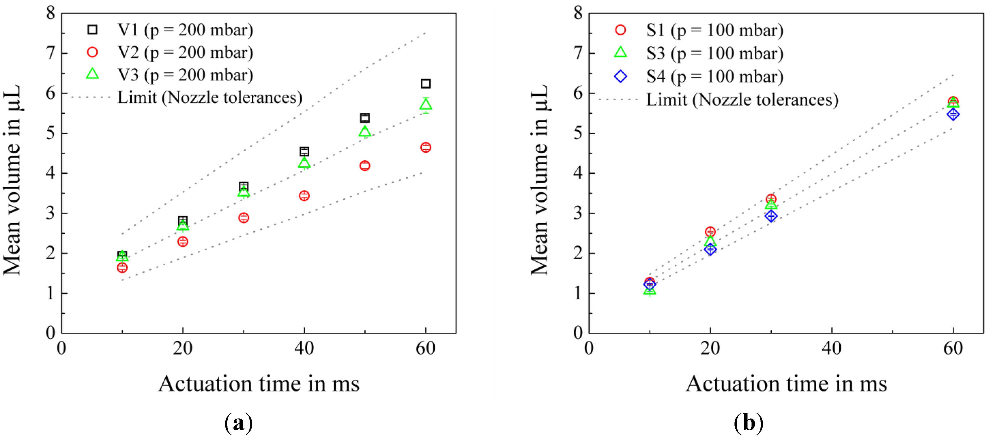
4.2. Impact of Fabrication Tolerances of the Nozzle on the Tip-to-Tip CV

A further considerable influence factor on the valve performance, namely the tip-to-tip CV [1] is given by fabrication tolerances of the nozzle. Since the inner diameter of the nozzle affects the fluidic resistance of the valve by a power of four, the established liquid flow per pressure depends strongly on the nozzle geometry (see Equation (5)). In order to evaluate this influence, three injection molded valves (S1, S3, and S4) having a PI capillary (ID = 223 ± 6.4 μm, L = 5.5 ± 0.5 mm) as nozzle have been compared to the performance of three valves (V1, V2, V3) having the same design, but that were fabricated by 3D printing and that had manually assembled steel capillaries, featuring higher fabrication tolerances (ID = 200 ± 15 μm, L = 5.5 ± 0.5 mm), especially as far as the diameter is concerned (cf. ±6.4 μm versus ±15 μm).
The length of the peak pulse in the experiments is again 5 ms at 5 A, while the duration of the hold current (4 A) is varied between 0 and 55 ms. The actuating pressure is set to 200 mbar for the valves featuring the steel capillaries (V1 to V3) and 100 mbar for the injection molded valves S1, S3, and S4 with PI capillaries as nozzles. The results of this characterization are shown in Figure 9.
Figure 9. Each data point states the mean volume of 24 dispenses. The inner dashed line is the linear fit to all data points, the outer dashed lines show the maximum respectively minimum volume calculated for the largest respectively smallest possible nozzles according to the given tolerances of the capillaries (a) Dosing performance of three valves with a steel capillary as nozzle. (b) Dosing performance of the injection molded valve with PI capillaries. Properties of these valves are listed in Table 2.
Micromachines 06 00423 g009
For a nozzle having a nominal inside diameter of 200 μm, one can expect, according to Equation (5), a theoretical mean flow rate of 142.8 μL/s for an actuating pressure of 200 mbar. At an internal diameter tolerance of ±15 μm, the theoretical average flow rate varies in the worst case by about ±31.5% from its mean value in the range between 104.5 μL/s (73%) and 190.7 μL/s (136%) (see corresponding limits given by dashed lines in Figure 9). In Figure 9a, the results for three different valves with nozzles featuring the mentioned tolerances above are shown. The mean measured tip-to-tip CV of 14.8% is even a bit smaller than expected, implying that the actual inner diameter tolerance of the nozzles could be smaller than specified by the manufacturer.
The theoretical consideration for the PI capillaries (ID = 223 ± 6.4 μm) results in an average flow rate of 110.37 μL/s for an applied pressure of 100 mbar and will vary about ±11.5% from its mean value in the range of between 98.2 μL/s (89%) and 123 μL/s (112%). Therefore, the expected tip-to-tip CV achieved with the PI capillaries should be smaller by a factor of approximately 3 as compared to the valves with steel nozzles. This is indeed proven in Figure 9b. The characterization results for the used PI capillaries in Figure 9b, showed a smaller tip-to-tip CV of 5.2%, which is well within the tolerance limits.
The intra-run CVs for all characterized valves are listed in Table 2. From the results shown, one can see that the two different fabrication methods used for the valve body, injection molding (S1 to S4) or 3D printing (V1 to V3), have no noticeable influence on the individual dosing performance. All valves showed an excellent performance with average intra-run CVs in the range from 0.9% to 2.3%.
Table 2. Precision data of three injection-molded and three 3D printed valves out of different fabrication batches having different nozzles (as shown in Figure 9). The CV i n t r a r u n ¯ was calculated as average over different volumes as displayed in Figure 9.
NumberNozzleMaterialBatchCVintra-run CV i n t r a r u n ¯
S1PI capillaryBORMED HD 850 MO (Injection molding)10.5%–3.7%1.4%
S3PI capillaryPurell RP 270 G (Injection molding)20.9%–4.8%2.3%
S4PI capillaryPurell HP 570 U (Injection molding)20.4%–1.9%0.9%
V1Steel capillaryVisijet EX 200 (3D printing)10.6%–3.2%1.3%
V2Steel capillaryVisijet EX 200 (3D printing)10.7%–2.6%1.6%
V3Steel capillaryVisijet EX 200 (3D printing)10.7%–3.4%1.8%

5. Conclusions and Summary

In summary, we successfully miniaturized a previously developed functional model of a dispensing valve without compromising its performance. The valve size could be reduced from an altogether outer diameter of 16.5 mm down to 8.5 mm. The reduced size enables the fabrication of an 8-channel dispensing head, arranging the valves in a 9 mm pitch for super-silent multi-channel processing. The reduced Joule heating entails less heat transfer to the sample liquid, thus improving the valve precision especially for longer operation times, thus higher volumes. This allows the utilization of temperature-sensitive liquids and reagents like blood, serum, enzymes, and proteins used in in vitro diagnostic applications. To overcome the closing force of the NC ring magnet high actuation currents are required. However the NC magnet entails a positive acceleration of the plunger during the closing process, thus guarantees a reliable droplet-tear off and the prevention of pending droplets.
The simple design in combination with the attached standard Luer Lock fitting enables easy handling of the valve and makes it compatible to a wide range of standard medical tubing material and commercially available reservoirs. The valve features a low dead volume of approximately 2.1 μL, minimizing the waste of expensive sample liquids needed in the area of molecular diagnostics and immunochemistry. The replacement of the previously used steel nozzles by high precision polyimide capillaries implied an enormous improvement in the tip-to-tip CV, from 14.8% down to 5.2%. The intra-run CV varies in the range between 0.2% and 4.8% for the studied volume range, considering all examined valves. The presented valve reveals comparable performance to standard high precision, non-disposable dispensing valves [1] at very low fabrication cost, which arise from the applied injection molding fabrication process.
This novel miniaturized and low-cost dispensing valve bridges the gap between standard pipetting technologies, handling samples down to the low microliter range, and nanoliter dispensing technologies that typically require expensive cleaning steps and are not suited for higher volume applications. Thus, it opens up new application fields for the high-throughput fabrication of miniaturized assays, e.g., for diagnostic applications. Overall, this low-cost valve will make dispensing applications more cost-effective and, therefore, more interesting to the market, since it combines high precision volume dispensing with cost-effectiveness and easy handling.

Acknowledgments

We gratefully acknowledge financial support from the German Federal Ministry of Education and Research (BMBF, contract number 16ES0058).

Author Contributions

Sabrina Kartman, Peter Koltay and Andreas Ernst conceived and designed the experiments. Sabrina Kartmanwas responsible for the conception of the valve design and Andreas Ernst for the electronics. Sabrina Kartman performed the experiments and analyzed the data together with Peter Koltay and Andreas Ernst. Sabrina Kartman was responsible for the drafting of the manuscript as well as preparing the figures and tables. Roland Zengerle and Peter Koltay supported data interpretation and edited the manuscript.

Conflicts of Interest

The authors declare no conflict of interest.

References

  1. Bammesberger, S.B.; Ernst, A.; Losleben, N.; Tanguy, L.; Zengerle, R.; Koltay, P. Quantitative characterization of non-contact microdispensing technologies for the sub-microliter range. Drug Discov. Today 2013, 18, 435–446. [Google Scholar] [CrossRef] [PubMed]
  2. Streule, W.; Lindemann, T.; Birkle, G.; Zengerle, R.; Koltay, P. PipeJet: A Simple Disposable Dispenser for the Nano- and Microliter Range. J. Lab. Autom. 2004, 9, 300–306. [Google Scholar] [CrossRef]
  3. Rose, D. Microdispensing technologies in drug discovery. Drug Discov. Today 1999, 4, 411–419. [Google Scholar] [CrossRef] [PubMed]
  4. Lee, S.; Kim, J. Development and characterization of a cartridge-type pneumatic dispenser with an integrated backflow stopper. J. Micromech. Microeng. 2010, 20, 015011. [Google Scholar] [CrossRef]
  5. Bammesberger, S.B.; Kartmann, S.; Tanguy, L.; Liang, D.; Mutschler, K.; Ernst, A.; Zengerle, R.; Koltay, P. A Low-Cost, Normally Closed, Solenoid Valve for Non-Contact Dispensing in the Sub-μL Range. Micromachines 2013, 4, 9–21. [Google Scholar] [CrossRef]
  6. Kong, F.; Yuan, L.; Zheng, Y.F.; Chen, W. Automatic Liquid Handling for Life Science: A Critical Review of the Current State of the Art. J. Lab. Autom. 2012, 17, 169–185. [Google Scholar] [CrossRef] [PubMed]
  7. Ravaud, R.; Lemarquand, G.; Lemarquand, V. Force and stiffness of passive magnetic bearings using permanent magnets. Part 1: Axial magnetization. IEEE Trans. Magn. 2009, 45, 2996–3002. [Google Scholar] [CrossRef]
  8. Mutschler, K.; Dwivedi, S.; Kartmann, S.; Bammesberger, S.B.; Koltay, P.; Zengerle, R.; Tanguy, L. Multi physics network simulation of a solenoid dispensing valve. Mechatronics 2014, 24, 209–221. [Google Scholar] [CrossRef]
  9. Avison, J. The World of Physics, 2nd ed.; Thomas Nelson and Sons Ltd: Cheltenham, UK, 1989. [Google Scholar]
  10. Liang, D.; Steinert, C.; Bammesberger, S.B.; Tanguy, L.; Ernst, A.; Zengerle, R.; Koltay, P. Novel gravimetric measurement technique for quantitative volume calibration in the sub-microliter range. Meas. Sci. Technol. 2013, 24, 025301. [Google Scholar] [CrossRef]
  11. Li, D.Q. Encyclopedia of Microfluidics and Nanofluidics; Springer: New York, NY, USA, 2008. [Google Scholar]
  12. SLI-Flow Meters for Life Science and Automation. Available online: http://www.sensirion.com/en/products/liquid-flow-sensors/industry-laboratory-devices/sli-universal-flow-meter/ (accessed on 2 February 2015).

