Article

Development of Micro-Grippers for Tissue and Cell Manipulation with Direct Morphological Comparison

1
Section of Forensic Medicine of the Department of Histological, Forensic & Orthopedic Sciences, Sapienza University of Rome, Piazzale Aldo Moro, 5-00185 Roma, Italy
2
Department of Mechanical and Aerospace Engineering, Sapienza University of Rome, Via Eudossiana, 18-00184 Roma, Italy
3
Department of Information Engineering, Electronic and Telecommunications, Sapienza University of Rome, Via Eudossiana, 18-00184 Roma, Italy
4
Department of Chemical Engineering Materials Environment, Sapienza University of Rome, Via Eudossiana, 18-00184 Roma, Italy
5
Department of Law, Philosophy and Economic Studies, Sapienza University of Rome, Piazzale Aldo Moro, 5-00185 Roma, Italy
6
Department of Dynamic and Clinical Psychology, Sapienza University of Rome, Via degli Apuli, 1-00185 Roma, Italy
7
Fondazione Bruno Kessler (FBK), Micro Nano Facility (MNF), Via S. Croce, 77-38122 Trento, Italy
*
Author to whom correspondence should be addressed.
Micromachines 2015, 6(11), 1710-1728; https://doi.org/10.3390/mi6111451
Submission received: 2 September 2015 / Revised: 20 October 2015 / Accepted: 2 November 2015 / Published: 6 November 2015

Abstract

:
Although tissue and cell manipulation nowadays is a common task in biomedical analysis, there are still many different ways to accomplish it, most of which are still not sufficiently general, inexpensive, accurate, efficient or effective. Several problems arise both for in vivo or in vitro analysis, such as the maximum overall size of the device and the gripper jaws (like in minimally-invasive open biopsy) or very limited manipulating capability, degrees of freedom or dexterity (like in tissues or cell-handling operations). This paper presents a new approach to tissue and cell manipulation, which employs a conceptually new conjugate surfaces flexure hinge (CSFH) silicon MEMS-based technology micro-gripper that solves most of the above-mentioned problems. The article describes all of the phases of the development, including topology conception, structural design, simulation, construction, actuation testing and in vitro observation. The latter phase deals with the assessment of the function capability, which consists of taking a series of in vitro images by optical microscopy. They offer a direct morphological comparison between the gripper and a variety of tissues.

1. Introduction

Tissue and cell manipulation is a complex task that currently represents an open problem in the rapidly-changing context of bio-engineering.
Some of the most promising devices are based on ultrasonic wave fields [1,2,3,4]. Ultrasonic particle manipulation was described extensively in a recent review [5], where the use of ultrasound is illustrated for the purpose of inducing and retaining cell-to-cell contact. Many other recent examples are available in the literature. For example, an optical tweezers setup has been proposed for controlled cell capture and array formation [6] to study a highly-effective Hog1 inhibitor in a single cell. Furthermore, using the concept of the flow reduction mechanism [7], a high resolution cell manipulation system was constructed by combining a macro-scale actuator and a macro-scale position sensor. Contact-free systems, like optical or magnetic tweezers, have the advantage of eliminating adhesive effects. On the other hand, generally, the allowable forces on micro-objects are quite small, and the processes are limited to specific materials, in terms of shape and physical properties. For example, biological cells could be damaged by the elevated power of a laser beam [8].
Contact-based manipulating systems can manipulate a wide range of materials and are able to exert considerable forces on the micro-object. Since adhesive forces play a significant role, a convenient releasing strategy could be necessary. Direct mechanical handling seems more complex, since it must be implemented by using purely mechanical devices, such as microgrippers or nanomanipulators.
Some simple and flexible mechanical structures can be used to develop either linear [9] or rotary [10,11] comb drives.
However, in many other cases, the mechanical structure of the devices suggests a specific topology, which is due to the relative position of flexible and pseudo-rigid sub-parts. Sometimes, the former consist of long and narrow beams that, taking advantage of their distributed compliance, deflect along their neutral axis. Some mechanical structures can be built by combining the action of such beams, as reported, for example, in [12,13]. The attitude of conferring mobility to a structure by means of flexible elements with distributed compliance can be exploited to obtain more complex gripping systems. In many cases, the property of the parallelogram structure has been used to create new micro-grippers [14,15,16,17,18], while, in other cases, distributed compliance made the structure motion as complex as in traditional mechanisms [19,20,21].
The idea of mimicking articulated mechanisms to build new gripping-compliant mechanism has been stressed since 2005, when a general purpose atlas of articulated four-bar linkage-based grippers, developed in 1993 [22], was integrally recopied, in its original shape and entirety, in another paper [23] dedicated to micro-grippers. As a matter of fact, another effective way to construct micro-grippers is the adoption of lumped compliance. In this kind of structure, small sub-parts are more flexible than the rest of the system. The device mobility is effectively due to the selective compliance of such parts, giving rise to concentrated or lumped elasticity. Recently, some micro-grippers were designed by using the same principle of concentrating flexibility in flexure hinges locally embedded in some portion of the whole structure [24,25,26,27,28]. This choice permits the achievement of more complex motion and a higher number of degrees of freedom.
As mentioned above, actuation can be provided by means of electrostatic actuators, either linear [9,17,29] or rotary [11,30]. However, thermal actuation can be also a good strategy, such as, for example, electrothermal actuation [31,32,33,34,35] or shape memory alloy actuation [36,37,38]. Finally, piezoelectric actuation [39,40,41,42,43] represents, for many applications, the best choice, also using bimaterial piezoelectric (BPE) [44,45] or bimorph [46] types.
Generally, due to the application of the actuation force, the flexible elements undergo large deflections, both in the case of distributed and lumped compliance. During such deflections, two adjacent pseudo-rigid parts may experience a positional shift of their relative rotation center, which leads to an inconsistency with respect to the original design of the compliant system: in fact, as a final result, the whole system behaves differently from its design specifications. Furthermore, flexible parts can experience high stress levels.
Recently, a new conjugate surfaces flexure hinge (CSFH) flexure was proposed to improve the performance of compliant systems, especially in terms of displacement accuracy [47]. The gripper presented in this paper is based on this hinge and offers a number of advantages, like the possibility of adopting rotary comb drives as the actuation system, the intrinsic high rotation precision and low stress levels in the flexible elements.
The present paper is the result of the collaborative work of a multidisciplinary team composed of researchers with different backgrounds. This cooperation made it possible to integrate all stages of the device development: topological and conceptual design, actuation, construction and prototyping, testing and ethical aspects. The following paragraphs are dedicated to these different aspects of the device development.

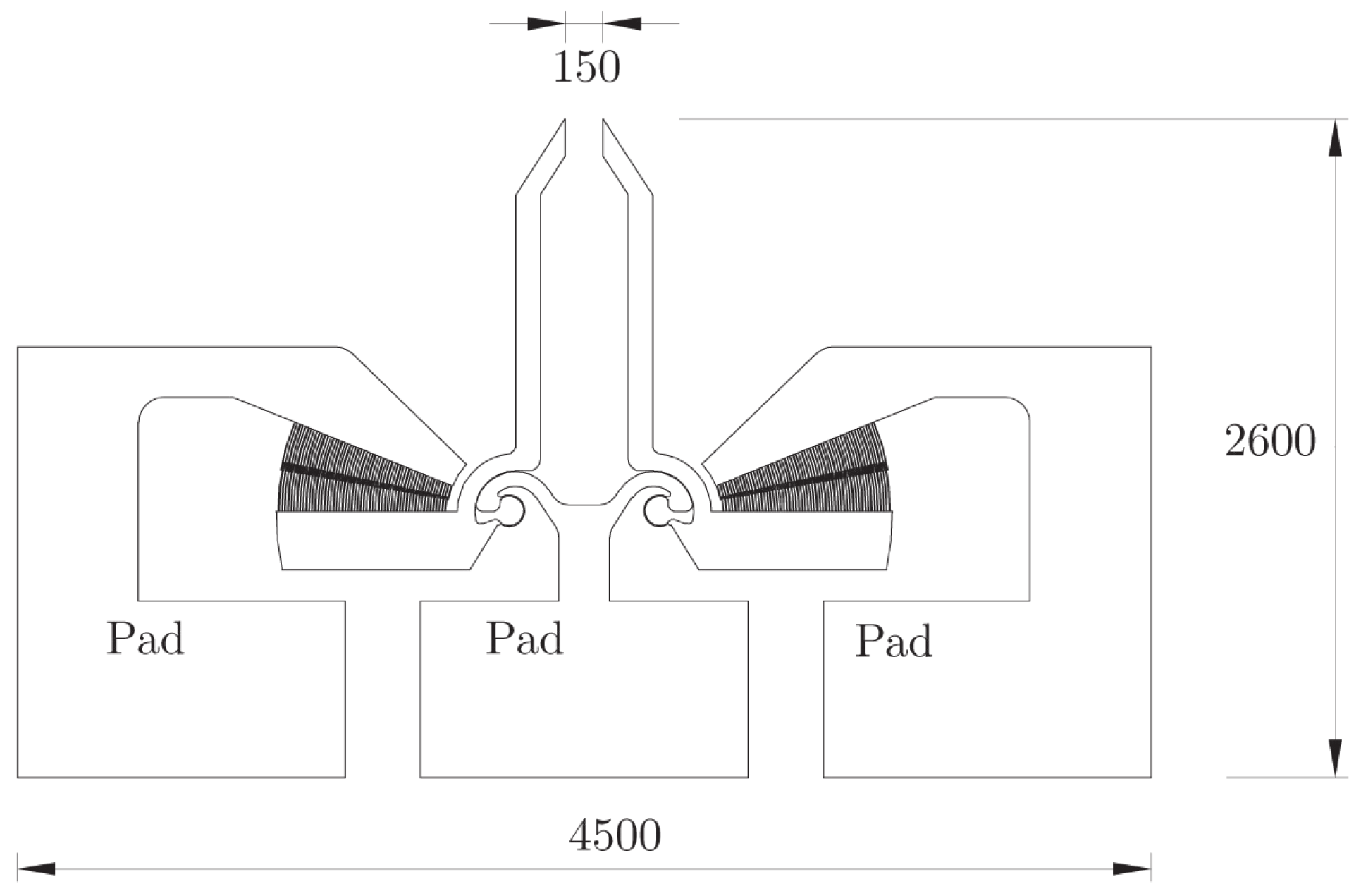
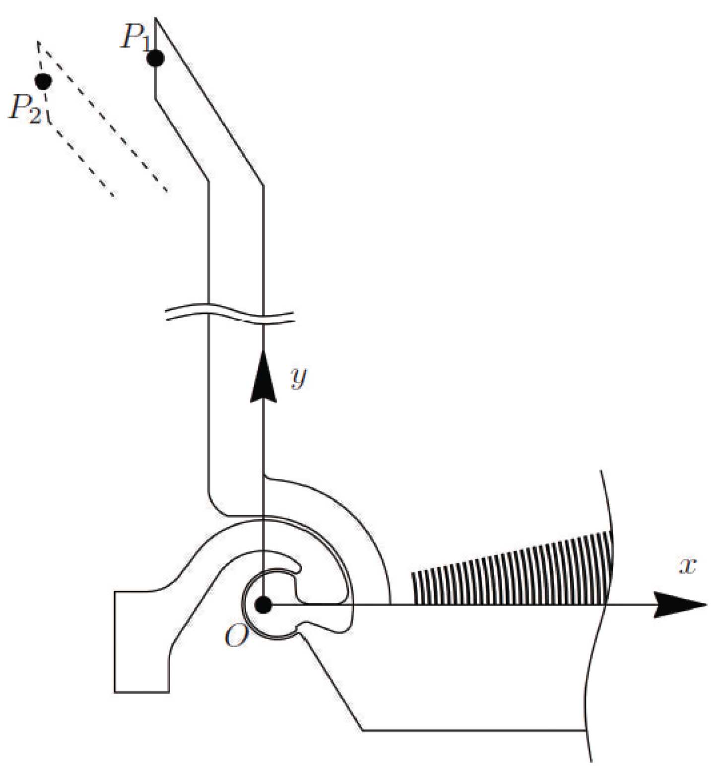
2. Design of a CSFH Silicon Micro Gripper

The first stage of construction consists of the topological and functional synthesis. Usually, the topological synthesis is performed by means of graph theory [22,48,49,50,51,52,53], while functional synthesis is performed by means of classical methods of kinematic synthesis for infinitesimal or finite motion [54,55,56]. Depending on the application, three classes of problems can be defined: function generator, rigid body guidance and path generator. Firstly, the devices are designed as standard mechanisms with classical joints, in particular revolute joints (hinges). After the generation of a feasible solution, a compliant mechanism is created starting from the essential information contained in the traditional mechanism. This task represents the reverse approach to the typical problem of generating a pseudo-rigid-body model from a compliant mechanism. According to this methodology, rather than applying optimization techniques to the morphological characteristics of the compliant mechanism, a kinematic synthesis problem can be solved by means of the classical methods of kinematics.
The mechanical device presented in this paper is the result of a long evolutionary design process. After preliminary works [57,58,59,60,61,62], a new concept CSFH was introduced [63] with the purpose of extending freedom in MEMS design. This hinge consists of a pair of pseudo-rigid bodies, which are in contact along a portion of conjugate circular surfaces and which are joined together by means of an elastic beam (linear, circular or with other shape), which has the following peculiar property:
The center of its elastic weights is positioned in the center of the circular arc which represents the conjugate surfaces.
In this way, two effects are obtained:
  • The motion of the compliant mechanism (equipped with CSFHs) is very similar to the motion of the classical mechanisms that have been synthesized by means of the well-known kinematic methods;
  • The overall stress is minimized in the flexible element.
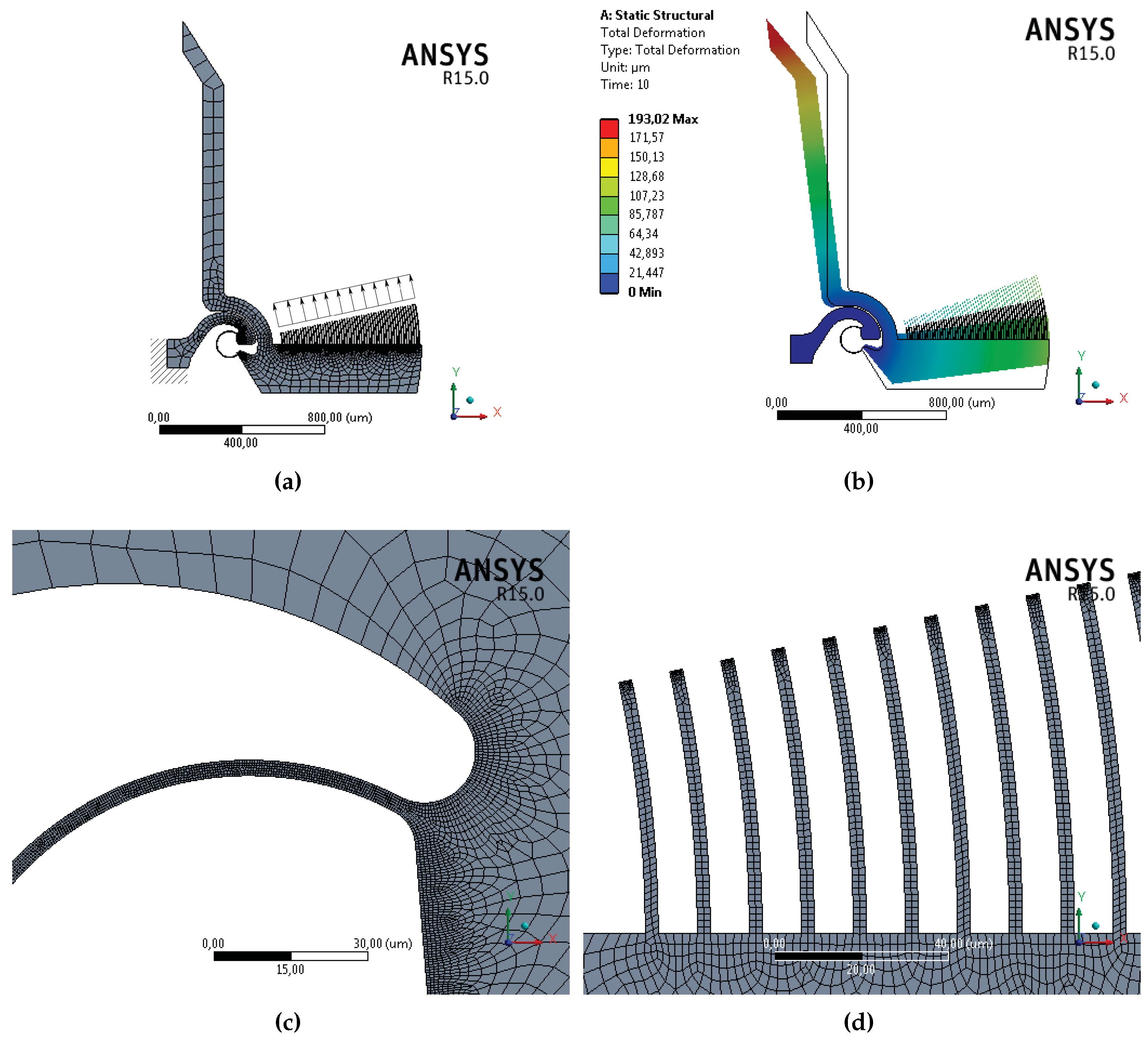
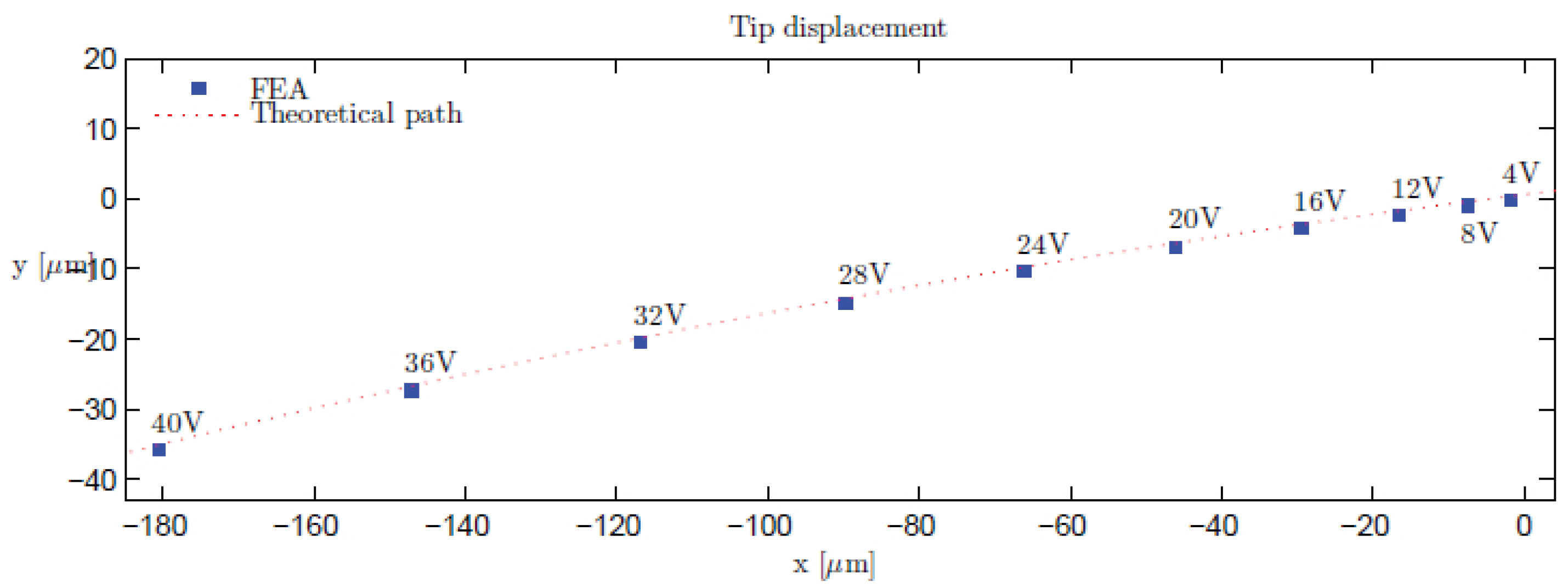
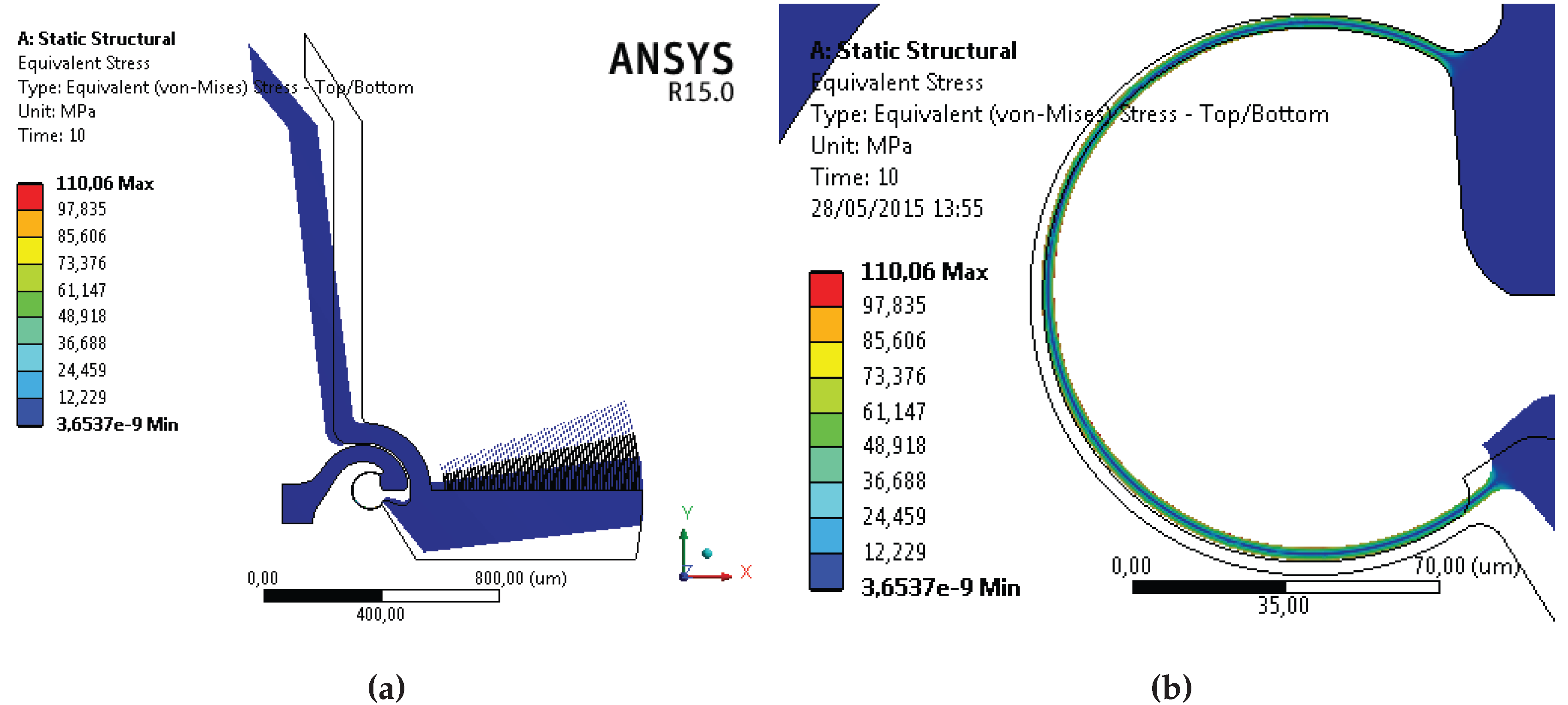
The developed gripper consists of one on-chip, single block, MEMS device, which makes use of two CSFHs. Further details about CSFH, concerning more specific subjects, such as dimensioning and construction, can be found in previous contributions [47,64,65]. In the present paper, the CSFH has been adopted in order to build the new gripper, whose corresponding mask is reported in Figure 1. In this first layout, the peculiarity of the device consists of the adoption of the CSFH hinge, which is able to work with as good an approximation as a normal revolute joint.
Figure 1. Mask corresponding to the conjugate surfaces flexure hinge (CSFH) microgripper, pads and overall dimensions (μm).
Micromachines 06 01451 g001

3. Simulation

After the conceptual design stage and before constructing the wafer mask, device simulation is a necessary step to ascertain if the system is able to fulfill all of the requirements. In the present investigation, a commercial finite elements analysis (FEA) package (ANSYS) has been adopted to evaluate the static response of the microgripper to the action exerted by the radial comb drive.
With reference to Figure 2a, a fixed support is introduced on the bottom left part of the structure, to simulate the clamping effect of the silicon oxide layer. The actuator action is modeled as a series of electrostatic forces F, schematically represented in the figure, each one acting perpendicularly to the free-end section of the movable finger and having magnitude equal to [66]:
F = ϵ h V 2 g
where ϵ is the dielectric constant of the air, h is the thickness of the finger, g is the radial distance between the movable and fixed finger and V is the applied voltage. Figure 2a shows the generated mesh, composed of 27,123 nodes and of 20,955 elements. The mesh is properly refined in the constant curvature beam and in the fingers’ regions, as shown in Figure 2c,d, respectively. A multi-step simulation is conducted, considering an applied voltage ranging from 4 to 40 V, by steps of 4 V. An additional simulation is conducted for an applied voltage equal to 11 V. For each voltage value, the force acting on the finger is calculated by means of Equation (1), by a total of 56 fingers. Nonlinearity due to large deflections is considered in the analysis setup. Anisotropic silicon is selected as the material, and an anisotropic formulation of elasticity is considered [67]. Figure 2b shows the total displacement corresponding to the last step of the simulation (40 V). Figure 3 shows the von-Mises equivalent stress distribution corresponding to the final step of the simulation (40 V). While the constant curvature flexure presents the highest stress values (Figure 3b), the major part of the structure shows stress values close to zero (Figure 3a). Then, assuming equal to zero the deformation of the free-end section of the jaw, it is possible to consider the displacement of the section as a rigid displacement. Under this assumption, and with reference to Figure 4, the coordinates of the center of rotation C r are given by [68]:
x C r = 1 2 x 1 + x 2 - y 2 - y 1 cot θ 2 - θ 1 2
y C r = 1 2 y 1 + y 2 + x 2 - x 1 cot θ 2 - θ 1 2
where x i , y i , are the coordinates of the tip point P (the mid-point of the free-end section) attached to the rigid jaw in the neutral ( P 1 ) and deformed ( P 2 ) configurations and θ i , represents the body orientation in the two mentioned configurations. The origin O of the local reference frame R { O , x , y , z } is positioned on the center of the elastic weights of the flexures.
By iterative FEA simulations, it is possible to obtain a map of the different positions of the tip point P for the set of the applied voltages. Figure 5 shows a portion of the workspace where such points are reported. By setting a new reference frame for the analyzed planar spot for which P = 0 , 0 , 0 for V = 0 , it becomes evident that the smallest displacements correspond to small values of the voltage. In Figure 5, the red dotted line represents the theoretical path of point P. It is worth noticing that this curve is a very good approximation of an arc whose center is positioned in correspondence to the center of rotation C R and whose radius coincides with the oriented segment C R P ¯ .
Considering the position of the center C R of the finite rotation of the jaw and according to the assumption on which the CSFH is based, the most desirable outcome would be a null displacement of such a point: this would imply that the body rotates around a fixed rotation center. However, this ideal feature is not intrinsic for a flexure hinge, because it is difficult, in most cases, to maintain C R , even in a restricted region. Anyway, for the highest tension levels, the center C R changed its position by less than 2 μm.
Figure 2. Finite element analysis: mesh and load conditions (a); total displacement corresponding to the applied voltage of 40 V (b); mesh refinement in the flexure (c) and in the fingers (d).
Micromachines 06 01451 g002
Figure 3. Von-Mises equivalent stress distribution corresponding to the applied voltage of 40 V (a) and flexure detail (b).
Micromachines 06 01451 g003
Figure 4. Determination of the center of rotation: reference frame and nomenclature.
Micromachines 06 01451 g004
Figure 5. Tip displacements (point P) for different values of the applied voltage and the theoretical path of point P (dotted line).
Micromachines 06 01451 g005
Figure 6 displays the Cartesian coordinates of the center of rotation x C R and y C R for the same set of applied voltages. Up to 40 V of applied voltage, the maximum distance of the center of rotation to the center of the elastic weights is 1 . 51 μm along the x axis and - 1 . 05 μm along the y axis.
Figure 6. Cartesian coordinates in R { O , x , y , z } of the center of rotation for the set of the applied voltages.
Micromachines 06 01451 g006
The force exerted by the fingertip during manipulation can be easily controlled by means of the applied tension. In fact, a previous investigation [65] led to the validation of both a theoretical and a numerical approach to the simulation of the gripping force under quasi-static conditions.

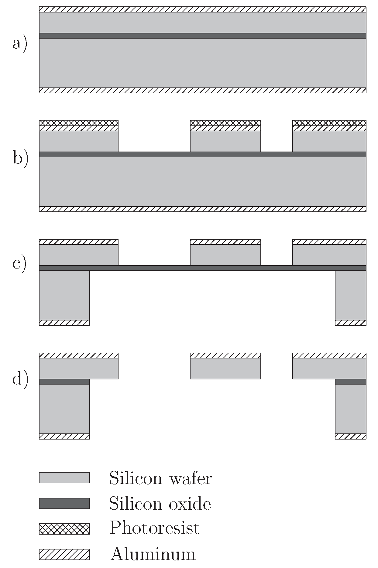
4. Technological Process Design and Actual Construction

Based on previous work and on the actual state of the art, the research group has decided to adopt a combined surface and bulk micro-machining technique applied on silicon on insulator (SOI) wafers.
The SOI wafers are often used for micro-electro-mechanical systems (MEMS) to obtain suspended structures, like cantilevers or resonators. In fact, the SOI frame is composed of a top layer of silicon, called the device layer, a middle layer of silicon dioxide, called the buried oxide (BOX), and a bottom layer, called the handle layer.
In this investigation, the devices were obtained as monolithic silicon-compliant mechanisms, with suspended and clamped parts. Two pads were used for the actuation of the rotary comb-drives. Four inch SOI wafer were selected with the following characteristics:
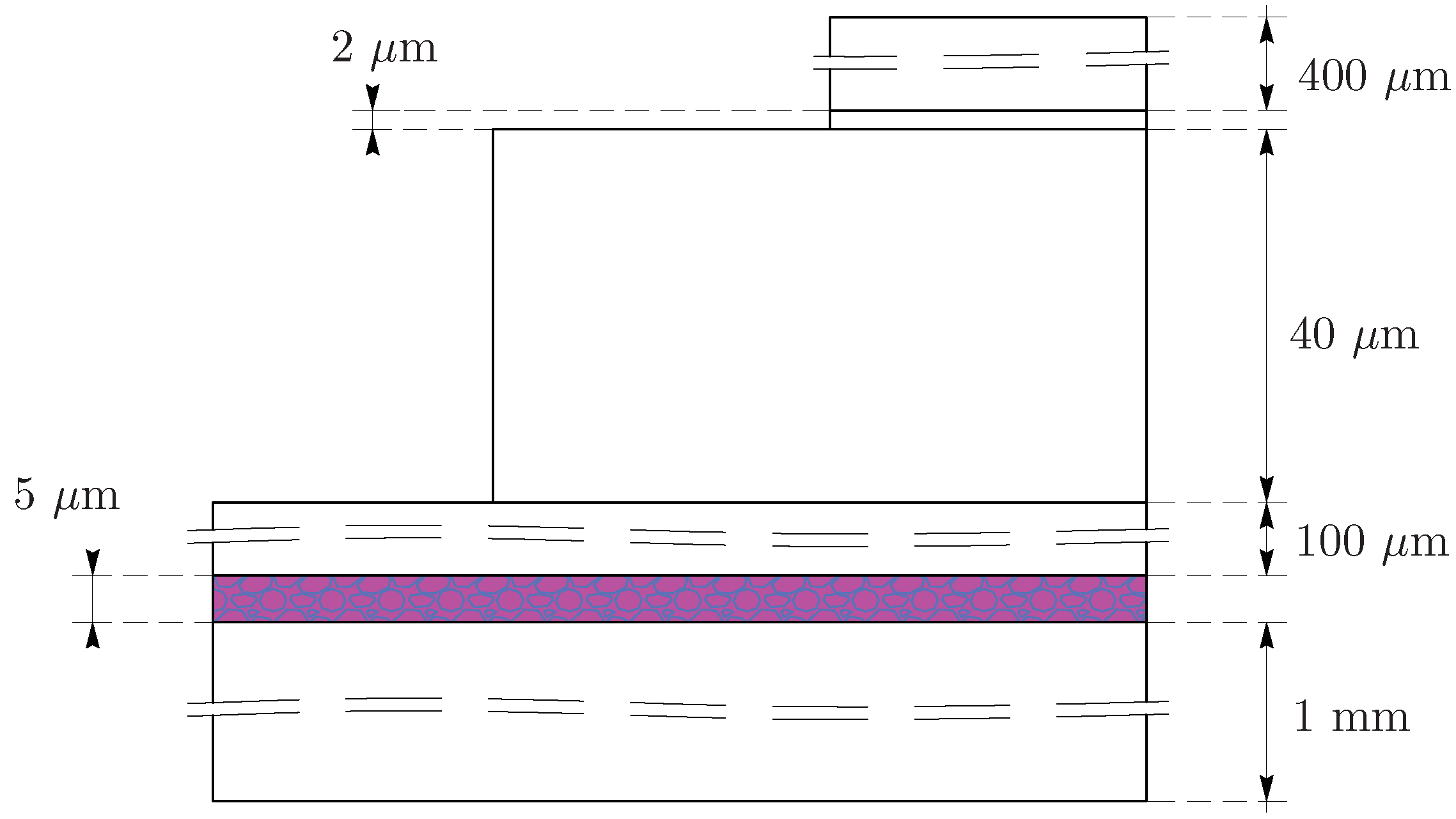
  • Device layer thickness of 40 μm;
  • Buried SiO 2 thickness of 2 μm;
  • Handle wafer thickness of 475 μm.
This kind of substrate suites our purposes very well and allows the realization of suspended structures by etching, separately, both the device and the handle silicon layers and, then, removing the buried oxide film. In this way, the top silicon parts resulted in being not in contact with the bottom parts.
The process sequence is based on Bosch process of DRIE (deep reactive ion etching). The full realization has been carried out at FBK-MNF.
SOI wafers were provided by Semiconductor Wafer Inc (SWI, Hsinchu, Taiwan). The corresponding technological steps are represented in Figure 7 and are herein briefly resumed for the sake of completeness.
  • The first step is the deposition of one 200 nm-thick layer of aluminum on both wafer sides by magnetron sputter deposition. An Eclipse sputter Physical Vapour Deposition (PVD) machine (OEM Group, Phoenix, AZ, USA) has been used at room temperature (Figure 7a).
  • A 750 nm-thick photoresist layer is deposited on the aluminum front layer by spin coating (OIR674, Fujifilm, Tokyo, Japan).
  • The third step consists of positioning the photolithographic mask, which contains the desired pattern, between the wafer and the UV source in order to perform the exposure (exposure tool: Karl Suss MA150 mask aligner (SUSS MicroTec, Garching, Germany) ).
  • The mask features are transferred on the sample by photoresist development by using an EVG E110 spin process tool (EV Group, Suben, Austria).
  • The unprotected aluminum layer is etched by a dedicated plasma etching process (Tegal6510 plasma etcher (Allwin21 Corp., Morgan Hill, CA, USA), Cl-HBr-O (23-20-20sccm), 60 W, 500 MHz).
  • A deep reactive ion etching is then applied to the masked SOI wafer (Alcatel Micromachining Systems MS200 (Alcatel Micromachining Systems, Annecy, France), Bosch proprietary process sequence, chuck temperature −12 C).
  • The process stops when the deep etching reaches the buried silicon oxide layer, obtaining a solid device constrained to the silicon oxide layer (Figure 7b).
  • The same process chain is repeated on the bottom part, generating a tridimensional-shaped layer on both sides, joined by a continue layer of silicon dioxide (Figure 7c).
  • Finally, the exposed silicon dioxide is etched using Texas Instruments etching solution H 2 O : CH 3 COOH : 40% NH 4 F at a 1:1:1 ratio) to preserve aluminum, and the floating parts are separated (Figure 7d).
Figure 7. Process phases adopted for the realization of the device. (a) Deposition of aluminum layer on both wafer sides by magnetron sputter deposition; (b) DRIE process applied to the device layer; (c) DRIE process applied to the handle layer; (d) etching of the exposed silicon dioxide layer.
Micromachines 06 01451 g007
Some preliminary test have shown the presence of the following problems:
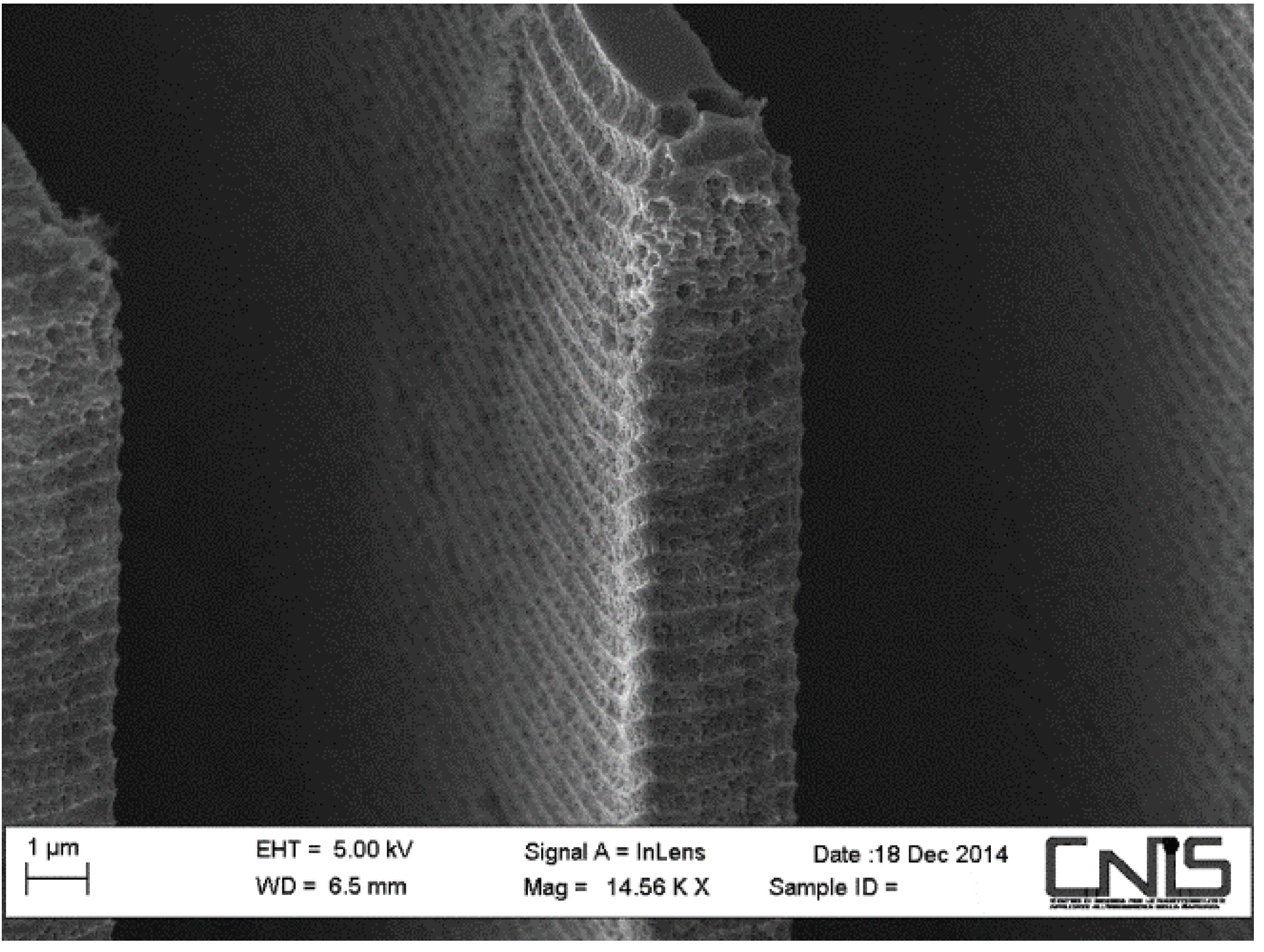
  • Loading effects, due to the great difference between opening areas, plasma etching shows the limitations of etching homogeneity with respect to openings dimensions;
  • Grass, unwanted silicon spikes due to resilient particles masking on the bottom of the etching cavity;
  • Scalloping, a characteristic roughness of the vertical surfaces produced by the two phases of the Bosch-type DRIE process.
The first problem has been solved by redesigning the photolithographic masks to reduce the opening areas exposed to the DRIE etching.
The second one has been solved by optimizing the reactive gas composition. The third one is yet under study, and it is aimed at reducing the scalloping gap profile. Once the realization was concluded, devices were separated from the wafer for the test stage.
One of these sample prototypes has been analyzed with SEM, and the results are reported in Figure 8.
Figure 8. A SEM image of the gripper built by the research group.
Micromachines 06 01451 g008

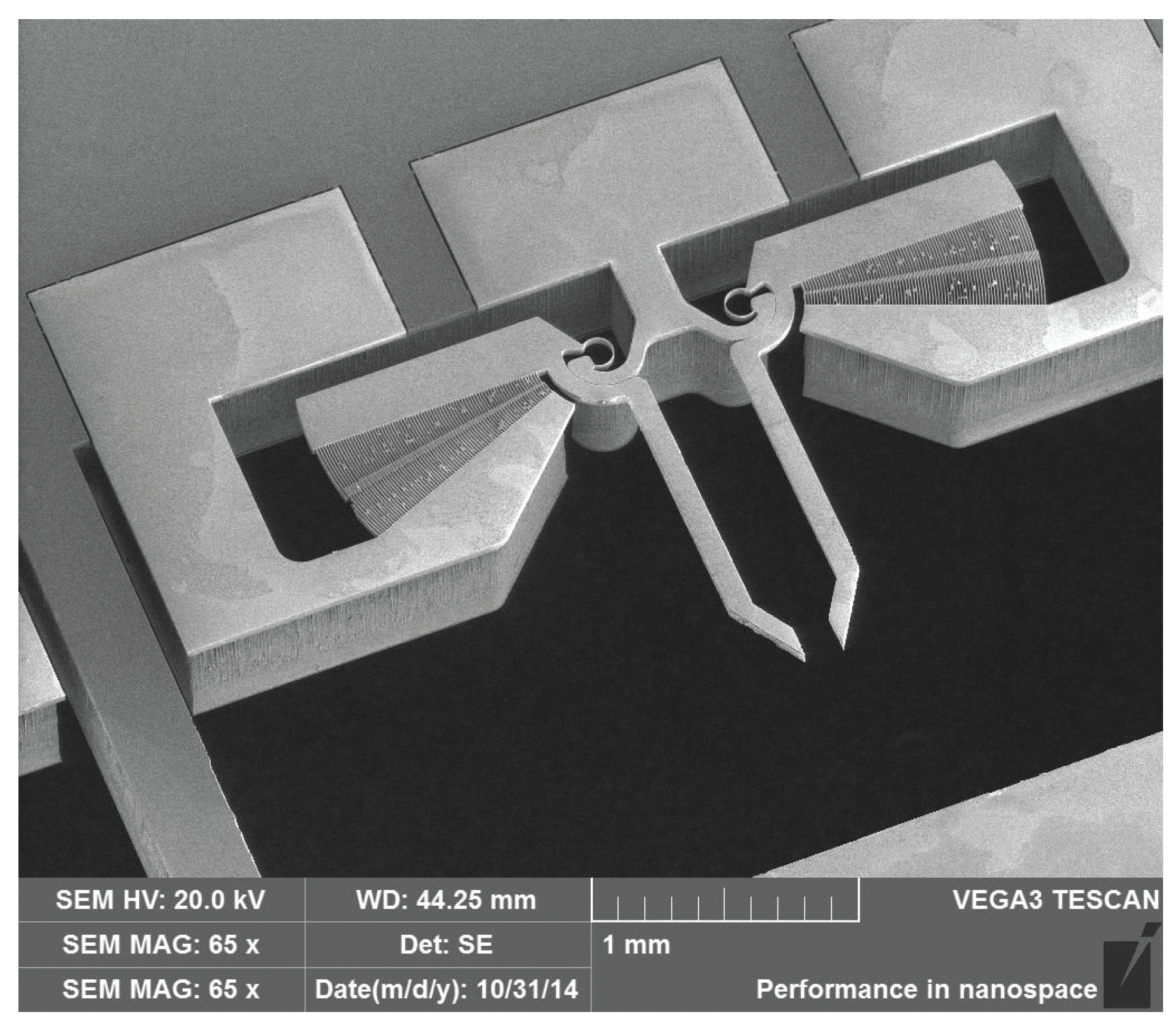
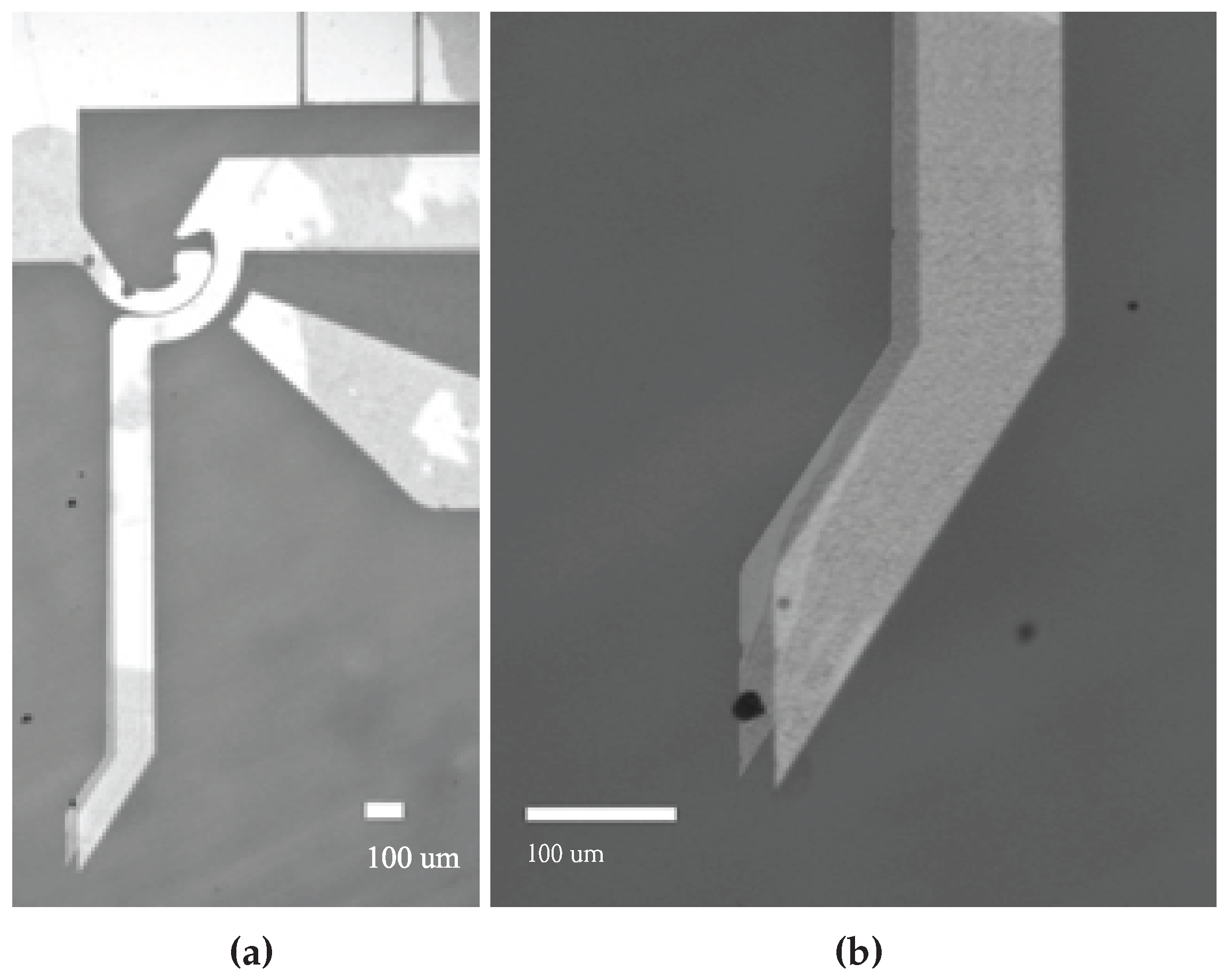
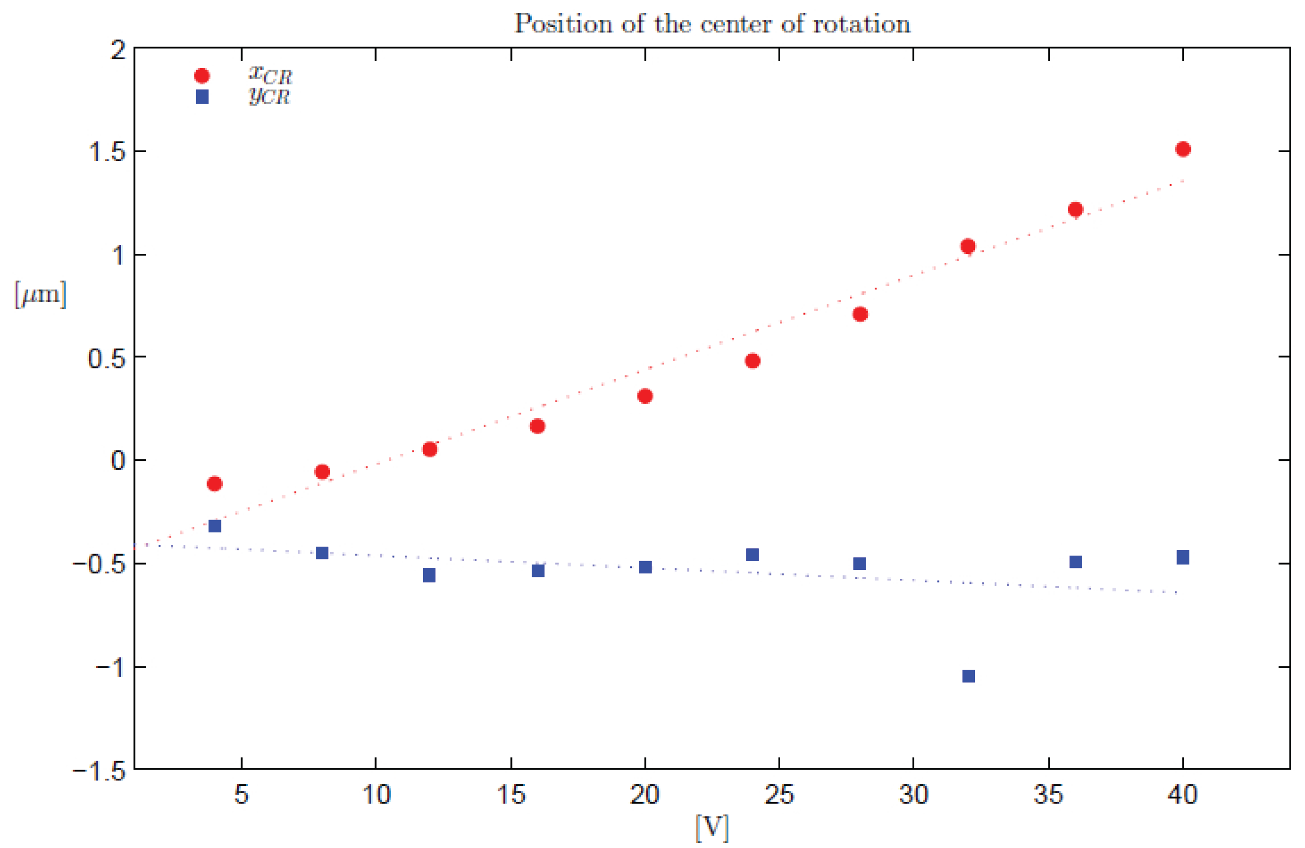
5. Experimental Testing on Prototype Samples

The realization process, because of the reduced microgripper dimension, yields a large number of devices ready to undergo testing procedures. At this point of the work, tests are mainly focused on evaluation of the feasibility of the comb drives and of the whole structure. For this purpose, they have been accurately positioned in a phase shifting interferometry profilometer equipped with both digital data acquisition and a micro-positioning tool. Contact pads of the devices under test have been wired to the external measurement circuit, which provides device controls. Actuation requires the setting of simple parameters, such as voltage and current. By applying a variable voltage, the clamping and releasing motion could be registered into a file. The image reported in Figure 9a is obtained by overlapping the neutral and most deflected configurations of the microgripper. During the test, jaw rotations could be measured, and some contact problems have been observed, due to the very narrow gaps between the fingers of the comb drive. The acquisition system provides more detailed images, such as reported in Figure 9b, thus giving the possibility to extract the positions of the tip point as a function of the applied voltage to the comb drive. These displacements of the tip point P (defined in Section 3) have been experimentally measured at different applied voltages and compared to those obtained by using finite element analysis. The result of this comparison is reported in Figure 10, where the simulated point P displacement (blue squares) is reported together with the experimental one (red circles) for three different voltage values (4, 8, 11 V). According to Figure 10, the tip displacements experimentally obtained using eight and 11 V were larger than those calculated via FEA. One possible explanation consists of a reduction of the nominal bending stiffness of the beam, due to some critical DRIE process parameters. For example, sulfur hexafluoride flow rate and the ratio of etching to passivation cycle time can produce wide opening trenches [69]. Furthermore, side effects of the process, such as undercut and scalloping, can further reduce the width both of the comb drive fingers and of the flexible beam. The reduction of the finger width implies an increasing gap between the fingers (g) and then a reduction of the exerted force ( F 1 / g , Equation (1)). On the other hand, a reduction of the beam width (b) produces a reduction of the bending stiffness that results in a more compliant behavior of the structure (for beams with a rectangular cross-section, K = E I b 3 ). As a qualitative example, Figure 11 shows undercut and scalloping effects on the vertical walls of the comb drive fingers.
Figure 9. Experimental test corresponding to the applied voltage of 11 V: gripper arm and comb drive (a) and jaw detail (b).
Micromachines 06 01451 g009
Figure 10. Comparison of the displacements obtained by the FEA model (blue squares) and the experimental measurements (red plain circles).
Micromachines 06 01451 g010
Figure 11. Scalloping effect on comb drive fingers.
Micromachines 06 01451 g011

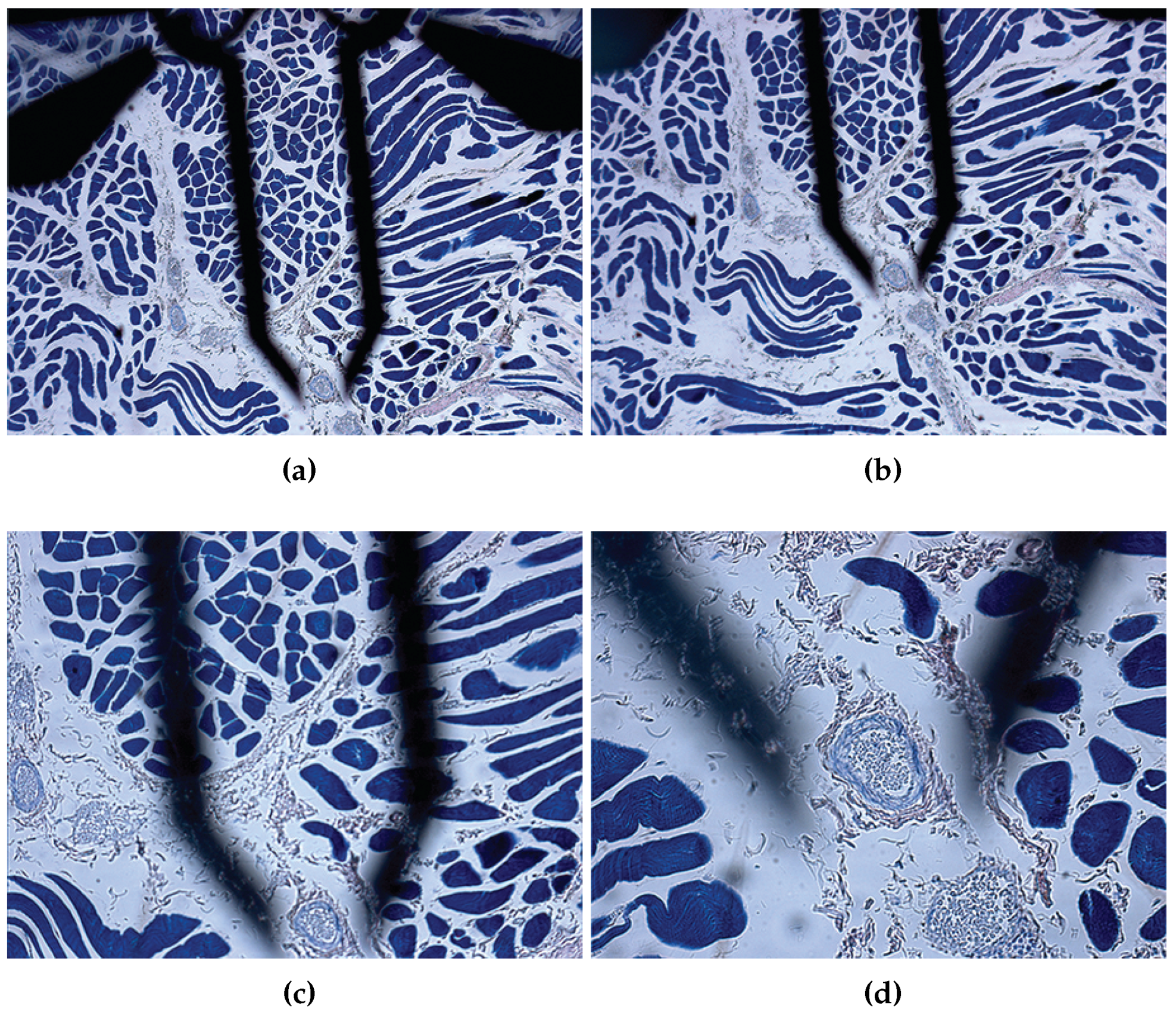
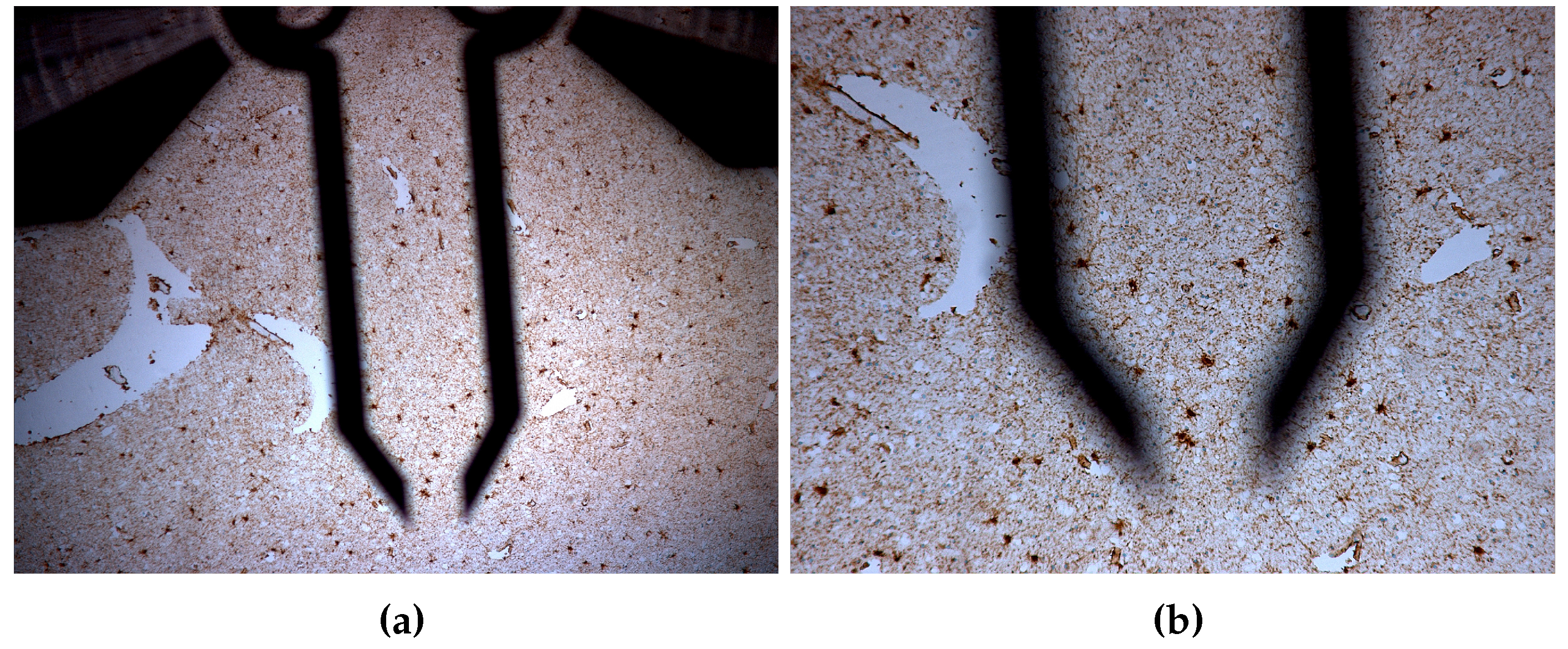
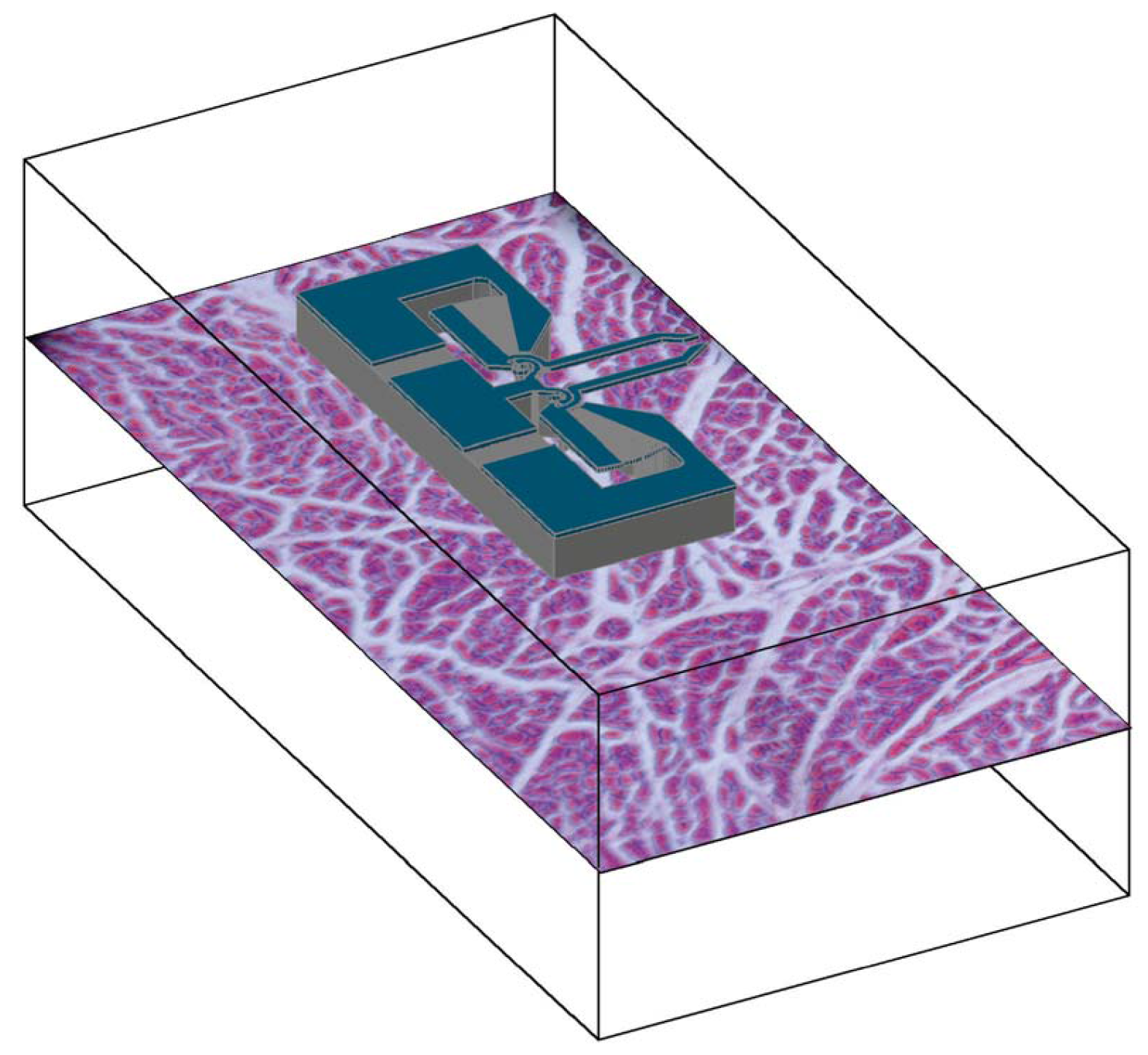
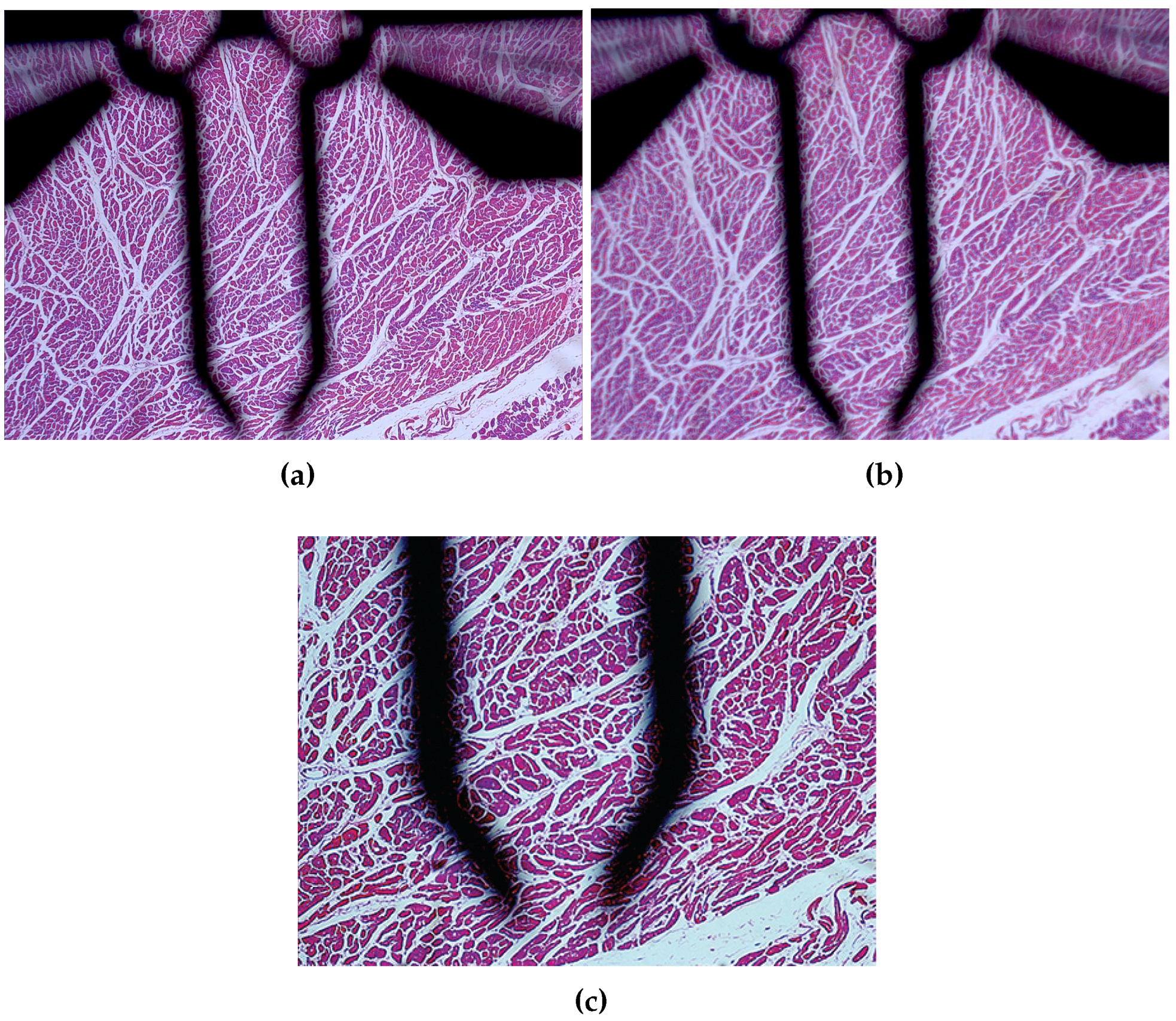
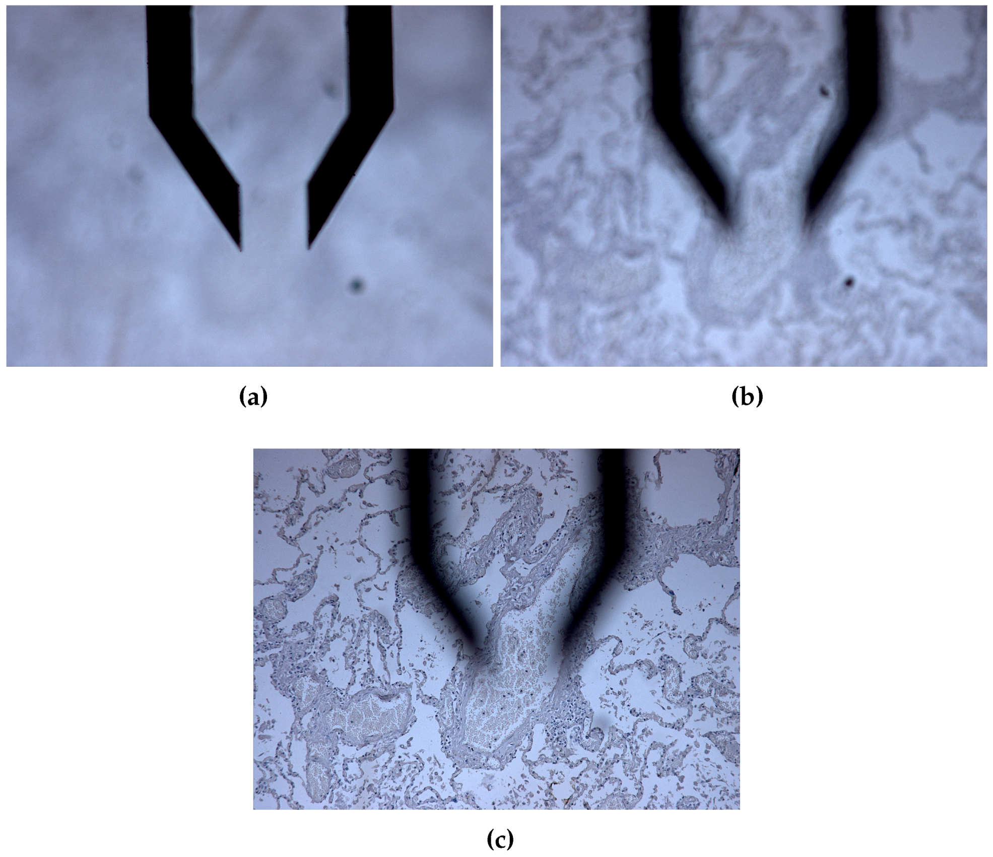
6. Morphological Analysis of in Vitro Microgripping Operations

Before in vivo experiments, it is necessary to plan an experimental campaign during which the device is tested in vitro. Unfortunately, the first experience showed that it is not so easy to prepare in vitro experimental tests with both artificial micro-devices and human cells or tissues. In fact, a certain amount of attention must be paid for the single preparation of the tissue samples, which requires some typical phases, such as fixing (for example, by chemical fixation with formaldehyde or other chemicals), dehydration, clearing, infiltration, embedding, sectioning and staining. Therefore, although it is relatively simple to obtain a variety of tissue samples ready for observation, it is very difficult to prepare an experiment where a gripper interacts directly with the tissues. The main problem consists of the inclusion of the device inside the tissue, which makes the fixing process very difficult to complete. For this reason, the device has been positioned over the sample coverslip, as illustrated in Figure 12.
Figure 12. Artificial reconstruction of the superposition of the tissue package and the microgripper blocks.
Micromachines 06 01451 g012
As represented in a vertical cross-section reported in Figure 13, a 5-μm tissue layer is disposed over a 1-mm glass support and protected by a 100-μm coverslip. Then, the 40-μm device layer is positioned over the coverslip. Since the device is obtained by means of the SOI wafer, there are also a 2 μm oxide and a 400 μm silicon handling or back layer. It is very evident that with this configuration, the act of gripping is impossible to implement because the device is on a plane that is different from the tissue plane. However, there is only a 100-μm separation gap between the device and the gripper, and so, optical microscopy can handle the situation by taking multiple images with different focal lengths. In this way, both the tissue and the gripper can be observed. Of course, the above-mentioned gap will make either the device or the tissue out of focus.
Figure 14 shows the histology of the left ventricle of the heart colored with hematoxylin-eosin (HE) and observed by a light microscope (Leica DRMB, Leica Microsystems GmbH, Wetzlar, Germany) with a 5×/0.12 PL Fluotar eyepiece (Leica Microsystems GmbH) (Figure 14a,b) and a 10×/0.30 PL Fluotar eyepiece (Figure 14c). The image shows the typical structure of the myocardial tissue in which connective tissue (thin pale gray fibers) runs between the bundles of muscle cells (pink). The white space separating the bundles becomes wider than in vivo during tissue preparation. In Figure 14c, it is possible to notice the paler perinuclear region of the nuclei of the cardiac fibers, found near the middle of the cross-section. The myocardium of the left ventricle is constituted by layers of bundles of muscle cells intimately interdigitated. Therefore, when the sample of cardiac tissue is cut by the microtome, before being colored, the muscle fibers show different sizes and shapes, roughly circular in cross-sections, and elongated in longitudinal sections.
Figure 13. Transverse section of the glass, tissue, glass, silicon, oxide and silicon layers.
Micromachines 06 01451 g013
Figure 14. Heart tissue with gripper (ac). (a) Heart (Focus a); (b) Heart (Focus b); (c) Heart (Focus c).
Micromachines 06 01451 g014
The comparisons between the tissue samples and the microgripper are reported in Figure 14 and Figure 15 (heart tissues), Figure 16 (brain tissue) and Figure 17 (lung tissue).
Figure 15 shows the histology of the left ventricle of the heart colored with phosphotungstic acid hematoxylin (PTAH) and observed by a light microscope (Leica DRMB) with a 5×/0.12 PL Fluotar eyepiece (Figure 15a,b), a 10×/0.30 PL Fluotar eyepiece (Figure 15c) and a 20×/0.50 PL Fluotar eyepiece (Figure 15d). The bundles of muscle cells are colored in dark blue. Although the device and the tissue are in different planes, as described in Figure 13, Figure 15 offers a direct comparison of the gripper jaw opening run and of a real arteriole, which demonstrates the technical possibility, for the gripper, to clamp this kind of vessel. For convenience, arterioles are said to have a diameter of less than 100 μm. Larger arterioles have an obvious media, in which elastic fibers prevail on muscular ones, and an adventitial layer of connective tissue. The arteriole in the figure is a smaller one (the diameter is about the gripper jaws’ distance, 150 μm), and has a media layer of only a few cells in thickness (thickness of 20 μm on average), in which muscular fibers prevail on elastic ones.
Figure 16 shows a sample of brain tissue colored with immunohistochemistry (IHC). An antibody anti-glial fibrillary acid protein (GFAP) was used in order to identify astrocytes (brown), characteristic star-shaped glial cells involved in the physical structuring of the brain.
Finally, Figure 17 shows three images of lung tissue samples at three different focal distances. The images show the histology of the lung tissue colored with immunohistochemistry, counterstained with hematoxylin and observed by a light microscope (Leica DRMB) with a 20×/0.50 PL Fluotar eyepiece with three different foci (a, b, c). It is possible to easily distinguish the lung’s alveoli thanks to their thin wall composed of a single layer of connective tissue and numerous capillaries, also lined with single squamous epithelium. The slide shows the gripper clamping a venule of about 150 μm in diameter.
Figure 15. Heart and gripper with different focus distances. (a) Heart (Focus a); (b) Heart (Focus b); (c) Heart (Focus c); (d) Heart (focus d).
Micromachines 06 01451 g015
Figure 16. Brain tissue and gripper at different focus distances. (a) Brain (Focus a); (b) Brain (Focus b).
Micromachines 06 01451 g016
Figure 17. Lung tissue with gripper (ac). (a) Lung (Focus a); (b) Lung (Focus b); (c) Lung (Focus c).
Micromachines 06 01451 g017

7. Future Developments

In this section, some future developments concerning the next possible experimental test stands, some power supply strategies and some ethical implications are presented. These further steps will enlarge the applicative range to unusual fields, like, for example, psychology and psychophysiology. In fact, in the case of both cognitive and sensorial disabilities, the role of wearable devices could support and integrate lost sensory functions. As far as blindness is concerned, for example, they are planned to be used to construct space-maps, which help persons in motion and orientation.

7.1. Tests Development

In the further developments of the investigation, a new group of tests will be performed in such a way that the micro-device is exactly on the same plane as the tissue. One feasible way to achieve this result consists of arranging the experiments with smear tests. For example, in cytopathologic tests, the organic material is smeared across a glass microscope slide for subsequent staining and microscopic examination. With this kind of test, the interaction between the artificial craft and the tissue, or the solute cells in saline drops, can be studied to provide experimental information and feedback to improve actuation and control.
Furthermore, forthcoming prototypes will be realized by means of a more elaborated process, taking advantage of the insulator layer of silicon dioxide and of a reduced handle layer, to electrically insulate the gripper jaws.

7.2. Power Supply

It is worth noting that the required voltages and current to actuate this first prototype device are quite low. Therefore, the actual design is paving the way for a low power device that is going to be developed in the near future. In fact, starting from the present device version, a design revision is planned in order to further reduce the power consumption, thus opening the possibility to use “non-conventional” power sources. In other words, the power strategy is going to be taken into account together with the already considered kinematics and dynamics aspects for the next device realization. This approach will make the next version of the device even smaller and possibly wireless by integrating a power source based on the energy harvesting concept.
There are different power and actuation strategies, although our attention has been focused on net zero energy systems. The strategy of net zero energy is a concept that has its origin in smart architecture, and has been applied to houses and buildings (see, for example, [70,71]). As far as MEMS are concerned, three fundamental functions have been identified [72], namely energy capturing, energy storage and drive actuation. Depending on the device’s overall dimensions, a power source and its corresponding energy density have to be identified first. Other than combustion reactants, thin-film solid-state batteries could be used for the micro-scale or, as an alternative, thermal energy might be stored as sensible heat of a proper material. There are also other interesting alternative solutions that will be analyzed for the sake of the present application: electrochemical cells, fuel cells, elastic strain energy, kinetic energy, magnetic field and pressure differential. However, in line with the idea of adopting a net zero energy strategy, regenerative power supply systems will be preferred [73], and so, batteries should be excluded, while micro-combustion systems, micro-turbines and heat engines could be adopted only in case they make use of waste energy. Using the same criterion, micro-fuel cells will not be considered for the sake of the present investigation, while an attempt will be made to ascertain the feasibility of solar cells, Seebeck effect-based thermoelectric systems, vibration or kinetic energy harvesting systems, some of which based on piezoelectric materials.

7.3. Ethics in the Design of Active Biomedical Devices with an Increasing Degree of Independence

One main feature of the constructed gripper is the presence of a CSFH hinge. Such a hinge will be used by the research group also for other MEMS that can be applied in the fields of biology and medicine, improving the psychological response of the patient, where MEMS have a chance to play a growing role. In fact, the possibility of using sensors and non-invasive devices seems to be one of the most important features in the process of acquiring physiological data with minimal influence on the recorded behavior [74,75].
Besides, the doctor-patient relationship has been regulated by ethical principles and legally binding regulations, and the employment of micro-devices in medicine will need to face the informed-consent of the patient, no maleficent action, safety in acting on the patient and safety of the materials. These are ethical themes that deserve to be investigated in a future work.

8. Conclusions

This paper presented the full development of a MEMS-technology-based device from its conceptual stage to the applications, considering topology conception, design, simulation, construction, testing and in vitro observation.
Comparison between experimental evidence and FEA simulation showed good agreement. The device showed promising performance in terms of kinematic behavior and energy requirements for the actuation system and applicability to various kinds of tissues. Finally, some ethical implications in the use of the device will be discussed in a future work.
The authors would like to point out that the reported working program output has an intrinsic added value that comes from the successful collaboration among partners belonging to a broad competence field, this being a condition that is more and more required to extract usable value from new technologies.

Acknowledgments

The research team was supported by Sapienza University, through the Grant: Ricerche di Ateneo 2014.

Author Contributions

This paper is the result of the cooperation of several researchers who have different backgrounds: functional design, mechanical engineering, material science, technology, microelectronics, process design for micro-electronics, continuum mechanics, thermo-fluid-mechanics, thermal engines, medicine, law. This consortium of members, which received financial aid from Sapienza University and FBK-MNF, have written the present paper in partial fulfillment of some reporting international activities. Although the paper is the result of genuine cooperative work, the following specific contributions can be stated. Rossana Cecchi was responsible for the morphological analysis of in vitro microgripping operations and gave a contribution to the definition of some ethic principles described in the paper. Matteo Verotti developed the simulation described in the third section and contributed to the development of the fifth section. Roberto Capata contributed to the development of the fifth section. Alden Dochshanov contributed to the drawing up of the first two sections. Giovanni B. Broggiato was the reference person for continuum mechanics and for finite element analysis. Rocco Crescenzi was the coordinator of the activities at the microelectronic lab. Marco Balucani was the reference person for the technological aspect of gripper design. Stefano Natali was the reference person for the experimental activities concerning observation and material characterization. Giovanna Razzano was responsible for the activities concerning ethics in the design of active biomedical devices with an increasing degree of independence. Franco Lucchese was the reference person for the applications of the gripper to biomedicine, neuroscience and psychology. Alvise Bagolini was responsible for the micro-silicon gripper design review and device realization. Pierluigi Bellutti was the reference person for the activities at FBK-MNF. Enrico Sciubba was the reference person for all aspects related to power, energy storage and harvesting. Nicola Pio Belfiore is the principal investigator and corresponding author.

Conflicts of Interest

The authors declare no conflict of interest.

References

  1. Bernassau, A.; Glynne-Jones, P.; Gesellchen, F.; Riehle, M.; Hill, M.; Cumming, D. Controlling acoustic streaming in an ultrasonic heptagonal tweezers with application to cell manipulation. Ultrasonics 2014, 54, 268–274. [Google Scholar] [CrossRef] [PubMed]
  2. Hagiwara, M.; Kawahara, T.; Yamanishi, Y.; Masuda, T.; Feng, L.; Arai, F. On-chip magnetically actuated robot with ultrasonic vibration for single cell manipulations. Lab Chip 2011, 11, 2049–2054. [Google Scholar] [CrossRef] [PubMed]
  3. Qiu, Y.; Demore, C.; Sharma, S.; Cochran, S.; Hughes, D.; Weijer, K. Multi-wavelength ultrasonic standing wave device for non-invasive cell manipulation and characterisation. In Proceedings of the 2011 IEEE International Ultrasonics Symposium (IUS), Orlando, FL, USA, 18–21 October 2011; pp. 188–191.
  4. Coakley, W.; Bardsley, D.; Grundy, M.; Zamani, F.; Clarke, D. Cell manipulation in ultrasonic standing wave fields. J. Chem. Technol. Biotechnol. 1989, 44, 43–62. [Google Scholar] [CrossRef]
  5. Wiklund, M.; Christakou, A.E.; Ohlin, M.; Iranmanesh, I.; Frisk, T.; Vanherberghen, B.; Önfelt, B. Ultrasound-induced cell-cell interaction studies in a multi-well microplate. Micromachines 2014, 5, 27–49. [Google Scholar] [CrossRef]
  6. Blomqvist, C.H.; Dinér, P.; Grøtli, M.; Goksör, M.; Adiels, C.B. A single-cell study of a highly effective Hog1 inhibitor for in situ yeast cell manipulation. Micromachines 2014, 5, 81–96. [Google Scholar] [CrossRef]
  7. Sakuma, S.; Kuroda, K.; Arai, F.; Taniguchi, T.; Ohtani, T.; Sakata, Y.; Kaneko, M. High resolution cell positioning based on a flow reduction mechanism for enhancing deformability mapping. Micromachines 2014, 5, 1188–1201. [Google Scholar] [CrossRef]
  8. Norregaard, K.; Jauffred, L.; Berg-Sorensen, K.; Oddershede, L.B. Optical manipulation of single molecules in the living cell. Phys. Chem. Chem. Phys. 2014, 16, 12614–12624. [Google Scholar] [CrossRef] [PubMed]
  9. Legtenberg, R.; Groeneveld, A.W.; Elwenspoek, M. Comb-drive actuators for large displacements. J. Micromech. Microeng. 1996, 6, 320. [Google Scholar] [CrossRef]
  10. Chang, H.; Zhao, H.; Ye, F.; Yuan, G.; Xie, J.; Kraft, M.; Yuan, W. A rotary comb-actuated microgripper with a large displacement range. Microsyst. Technol. 2014, 20, 119–126. [Google Scholar] [CrossRef]
  11. Yeh, J.A.; Chen, C.N.; Lui, Y.S. Large rotation actuated by in-plane rotary comb-drives with serpentine spring suspension. J. Micromech. Microeng. 2005, 15, 201. [Google Scholar] [CrossRef]
  12. Kim, C.J.; Pisano, A.; Muller, R. Silicon-processed overhanging microgripper. J. Microelectromech. Syst. 1992, 1, 31–36. [Google Scholar] [CrossRef]
  13. Rakotondrabe, M.; Ivan, I. Development and Force/Position Control of a New Hybrid Thermo-Piezoelectric MicroGripper Dedicated to Micromanipulation Tasks. IEEE Trans. Autom. Sci. Eng. 2011, 8, 824–834. [Google Scholar] [CrossRef] [Green Version]
  14. Wierzbicki, R.; Adda, C.; Hotzendorfer, H. Electrostatic Silicon Microgripper with Low Voltage of Actuation. In Proceedings of the International Symposium on Micro-NanoMechatronics and Human Science (MHS ’07), Nagoya, Japan, 11–14 November 2007; pp. 344–349.
  15. Hamedi, M.; Salimi, P.; Vismeh, M. Simulation and experimental investigation of a novel electrostatic microgripper system. Microelectron. Eng. 2012, 98, 467–471. [Google Scholar] [CrossRef]
  16. Piriyanont, B.; Moheimani, S.; Bazaei, A. Design and control of a MEMS micro-gripper with integrated electro-thermal force sensor. In Proceedings of the 2013 3rd Australian Control Conference (AUCC), Fremantle, WA, USA, 4–5 November 2013; pp. 479–484.
  17. Wierzbicki, R.; Houston, K.; Heerlein, H.; Barth, W.; Debski, T.; Eisinberg, A.; Menciassi, A.; Carrozza, M.; Dario, P. Design and fabrication of an electrostatically driven microgripper for blood vessel manipulation. Microelectron. Eng. 2006, 83, 1651–1654. [Google Scholar] [CrossRef]
  18. Zhang, Y.; Chen, B.K.; Liu, X.; Sun, Y. Autonomous robotic pick-and-place of microobjects. IEEE Trans. Robot. 2010, 26, 200–207. [Google Scholar] [CrossRef]
  19. Carrozza, M.C.; Eisinberg, A.; Menciassi, A.; Campolo, D.; Micera, S.; Dario, P. Towards a force-controlled microgripper for assembling biomedical microdevices. J. Micromech. Microeng. 2000, 10, 271. [Google Scholar] [CrossRef]
  20. Chen, T.; Chen, L.; Sun, L.; Li, X. Design and Fabrication of a Four-Arm-Structure MEMS Gripper. IEEE Trans. Ind. Electron. 2009, 56, 996–1004. [Google Scholar] [CrossRef]
  21. Kim, D.H.; Kim, B.; Kang, H. Development of a piezoelectric polymer-based sensorized microgripper for microassembly and micromanipulation. Microsyst. Technol. 2004, 10, 275–280. [Google Scholar] [CrossRef]
  22. Belfiore, N.P.; Pennestrì, E. An atlas of linkage-type robotic grippers. Mech. Mach. Theory 1997, 32, 811–833. [Google Scholar] [CrossRef]
  23. Tsai, Y.C.; Lei, S.H.; Sudin, H. Design and analysis of planar compliant microgripper based on kinematic approach. J. Micromech. Microeng. 2005, 15, 143. [Google Scholar] [CrossRef]
  24. Menciassi, A.; Eisinberg, A.; Mazzoni, M.; Dario, P. A sensorized μelectro discharge machined superelastic alloy microgripper for micromanipulation: Simulation and characterization. In Proceedings of the IEEE/RSJ International Conference on Intelligent Robots and Systems, Lausanne, Switzerland, 30 September–4 October 2002; Volume 2, pp. 1591–1595.
  25. Greminger, M.; Sezen, A.; Nelson, B. A four degree of freedom MEMS microgripper with novel bi-directional thermal actuators. In Proceedings of the 2005 IEEE/RSJ International Conference on Intelligent Robots and Systems (IROS 2005), Edmonton, AB, Canada, 2–6 August 2005; pp. 2814–2819.
  26. Chang, R.; Chen, C. Using Microgripper for Adhesive Bonding in Automatic Microassembly System. In Proceedings of the International Conference on Mechatronics and Automation (ICMA 2007), Harbin, China, 5–8 August 2007; pp. 440–445.
  27. Chronis, N.; Lee, L. Polymer MEMS-based microgripper for single cell manipulation. In Proceedings of the 17th IEEE International Conference on Micro Electro Mechanical Systems (MEMS 2004), Maastricht, The Netherlands, 25–29 January 2004; pp. 17–20.
  28. Sun, X.; Chen, W.; Fatikow, S.; Tian, Y.; Zhou, R.; Zhang, J.; Mikczinski, M. A novel piezo-driven microgripper with a large jaw displacement. Microsyst. Technol. 2015, 21, 931–942. [Google Scholar] [CrossRef]
  29. Chen, T.; Sun, L.; Chen, L.; Rong, W.; Li, X. A hybrid-type electrostatically driven microgripper with an integrated vacuum tool. Sens. Actuators A Phys. 2010, 158, 320–327. [Google Scholar] [CrossRef]
  30. Yeh, J.; Jiang, S.S.; Lee, C. MOEMS variable optical attenuators using rotary comb drive actuators. IEEE Photonics Technol. Lett. 2006, 18, 1170–1172. [Google Scholar] [CrossRef]
  31. Kim, K.; Liu, X.; Zhang, Y.; Sun, Y. Nanonewton force-controlled manipulation of biological cells using a monolithic MEMS microgripper with two-axis force feedback. J. Micromech. Microeng. 2008, 18, 055013. [Google Scholar] [CrossRef]
  32. Kim, K.; Liu, X.; Zhang, Y.; Cheng, J.; Yu, W.X.; Sun, Y. Elastic and viscoelastic characterization of microcapsules for drug delivery using a force-feedback MEMS microgripper. Biomed. Microdevices 2009, 11, 421–427. [Google Scholar] [CrossRef] [PubMed]
  33. Solano, B.; Wood, D. Design and testing of a polymeric microgripper for cell manipulation. Microelectron. Eng. 2007, 84, 1219–1222. [Google Scholar] [CrossRef]
  34. Zeman, M.J.F.; Bordatchev, E.V.; Knopf, G.K. Design, kinematic modeling and performance testing of an electro-thermally driven microgripper for micromanipulation applications. J. Micromech. Microeng. 2006, 16, 1540. [Google Scholar] [CrossRef]
  35. Zhang, R.; Chu, J.; Wang, H.; Chen, Z. A multipurpose electrothermal microgripper for biological micro-manipulation. Microsyst. Technol. 2013, 19, 89–97. [Google Scholar] [CrossRef]
  36. Chang, R.; Wang, H.; Wang, Y. Development of mesoscopic polymer gripper system guided by precision design axioms. Precis. Eng. 2003, 27, 362–369. [Google Scholar] [CrossRef]
  37. Kohl, M.; Just, E.; Pfleging, W.; Miyazaki, S. SMA microgripper with integrated antagonism. Sens. Actuators A Phys. 2000, 83, 208–213. [Google Scholar] [CrossRef]
  38. Kohl, M.; Krevet, B.; Just, E. SMA microgripper system. Sens. Actuators A Phys. 2002, 97–98, 646–652. [Google Scholar] [CrossRef]
  39. Chen, T.; Chen, L.; Sun, L.; Wang, J.; Li, X. A sidewall piezoresistive force sensor used in a MEMS gripper. In Intelligent Robotics and Applications; Springer: Berlin, Germany, 2008; pp. 207–216. [Google Scholar]
  40. Jeon, C.S.; Park, J.S.; Lee, S.Y.; Moon, C.W. Fabrication and characteristics of out-of-plane piezoelectric micro grippers using MEMS processes. Thin Solid Films 2007, 515, 4901–4904. [Google Scholar] [CrossRef]
  41. Kim, B.S.; Park, J.S.; Kang, B.H.; Moon, C. Fabrication and property analysis of a MEMS micro-gripper for robotic micro-manipulation. Robot. Comput. Integr. Manuf. 2012, 28, 50–56. [Google Scholar] [CrossRef]
  42. Zubir, M.N.M.; Shirinzadeh, B.; Tian, Y. Development of a novel flexure-based microgripper for high precision micro-object manipulation. Sens. Actuators A Phys. 2009, 150, 257–266. [Google Scholar] [CrossRef]
  43. Zubir, M.N.M.; Shirinzadeh, B.; Tian, Y. A new design of piezoelectric driven compliant-based microgripper for micromanipulation. Mech. Mach. Theory 2009, 44, 2248–2264. [Google Scholar] [CrossRef]
  44. Desmaële, D.; Boukallel, M.; Régniér, S. Actuation means for the mechanical stimulation of living cells via microelectromechanical systems: A critical review. J. Biomech. 2011, 44, 1433–1446. [Google Scholar] [CrossRef] [PubMed] [Green Version]
  45. Srinivasan, P.; Spearing, S. Optimal Materials Selection for Bimaterial Piezoelectric Microactuators. J. Microelectromech. Syst. 2008, 17, 462–472. [Google Scholar] [CrossRef]
  46. Jain, R.K.; Majumder, S.; Ghosh, B.; Saha, S. Design and manufacturing of mobile micro manipulation system with a compliant piezoelectric actuator based micro gripper. J. Manuf. Syst. 2015, 35, 76–91. [Google Scholar] [CrossRef]
  47. Verotti, M.; Crescenzi, R.; Balucani, M.; Belfiore, N.P. MEMS-Based Conjugate Surfaces Flexure Hinge. J. Mech. Des. Trans. ASME 2015, 137, 012301. [Google Scholar] [CrossRef]
  48. Belfiore, N.P. Atlas of remote actuated bevel gear wrist mechanisms of up to nine links. Int. J. Robot. Res. 1993, 12, 448–459. [Google Scholar] [CrossRef]
  49. Belfiore, N.P.; Pennestrì, E. Automatic sketching of planar kinematic chains. Mech. Mach. Theory 1994, 29, 177–193. [Google Scholar] [CrossRef]
  50. Belfiore, N.P. Distributed Databases for the development of Mechanisms Topology. Mech. Mach. Theory 2000, 35, 1727–1744. [Google Scholar] [CrossRef]
  51. Belfiore, N.P. Brief note on the concept of planarity for kinematic chains. Mech. Mach. Theory 2000, 35, 1745–1750. [Google Scholar] [CrossRef]
  52. Belfiore, N.P.; di Benedetto, A. Connectivity and redundancy in spatial robots. Int. J. Robot. Res. 2000, 19, 1245–1261. [Google Scholar] [CrossRef]
  53. Liberati, A.; Belfiore, N.P. A method for the identification of the connectivity in multi-loop kinematic chains: Analysis of chains with total and partial mobility. Mech. Mach. Theory 2006, 41, 1443–1466. [Google Scholar] [CrossRef]
  54. Pennestrì, E.; Belfiore, N.P. Modular Third-Order Analysis of Planar Linkages with Applications; American Society of Mechanical Engineers, Design Engineering Division (Publication) DE: New York, NY, USA, 1994; Volume 70, pp. 99–103. [Google Scholar]
  55. Pennestrì, E.; Belfiore, N.P. On the numerical computation of Generalized Burmester Points. Meccanica 1995, 30, 147–153. [Google Scholar] [CrossRef]
  56. Belfiore, N.P. Functional Synthesis of a New Class of Micro Electro-Mechanical Systems. In Advances in Soft Computing, Intelligent Robotics and Control; Fodor, J., Fuller, R., Eds.; Springer International Publishing: Cham, Switzerland, 2014; pp. 81–93. [Google Scholar]
  57. Belfiore, N.P.; EmamiMeibodi, M.; Verotti, M.; Crescenzi, R.; Balucani, M.; Nenzi, P. Kinetostatic Optimization of a MEMS-Based Compliant 3 DOF Plane Parallel Platform. In Proceedings of the IEEE 9th International Conference on Computational Cybernetics (ICCC 2013), Tihany, Hungary, 8–10 July 2013.
  58. Belfiore, N.P.; Simeone, P. Inverse kinetostatic analysis of compliant four-bar linkages. Mech. Mach. Theory 2013, 69, 350–372. [Google Scholar] [CrossRef]
  59. Belfiore, N.P.; Verotti, M.; Crescenzi, R.; Balucani, M. Design, Optimization and Construction of MEMS-Based Micro Grippers for Cell Manipulation. In Proceedings of the IEEE International Conference on System Science and Engineering (ICSSE 2013), Budapest, Hungary, 4–6 July 2013.
  60. Belfiore, N.; Balucani, M.; Crescenzi, R.; Verotti, M. Performance analysis of compliant mems parallel robots through pseudo-rigid-body model synthesis. In Proceedings of the ASME 2012 11th Biennial Conference on Engineering Systems Design and Analysis (ESDA 2012), Nantes, France, 2–4 July 2012; Volume 3, pp. 329–334.
  61. Nenzi, P.; Crescenzi, R.; Dolgyi, A.; Klyshko, A.; Bondarenko, V.; Belfiore, N.P.; Balucani, M. High density compliant contacting technology for integrated high power modules in automotive applications. In Proceedings of the Electronic Components and Technology Conference, San Diego, CA, USA, 29 May–1 June 2012; pp. 1976–1983.
  62. Balucani, M.; Belfiore, N.; Crescenzi, R.; Verotti, M. The development of a MEMS/NEMS-based 3 D.O.F. compliant micro robot. Int. J. Mech. Control 2011, 12, 3–10. [Google Scholar]
  63. Belfiore, N.P.; Prosperi, G.; Crescenzi, R. A SImple Application of Conjugate Profile Theory to the Development of a Silicon Micro Tribometer. In Proceedings of the ASME 2014 12th Biennial Conference on Engineering Systems Design and Analysis, Copenhagen, Denmark, 25–27 July 2014.
  64. Belfiore, N.; Broggiato, G.; Verotti, M.; Crescenzi, R.; Balucani, M.; Bagolini, A.; Bellutti, P.; Boscardin, M. Development of a MEMS technology CSFH based microgripper. In Proceedings of the 23rd International Conference on Robotics in Alpe-Adria-Danube Region (RAAD), Smolenice, Slovakia, 3–5 September 2014.
  65. Belfiore, N.P.; Broggiato, G.B.; Verotti, M.; Balucani, M.; Crescenzi, R.; Bagolini, A.; Bellutti, P.; Boscardin, M. Simulation and Construciton of a MEMS CSFH Based Microgripper. Int. J. Mech. Control 2015, 16, 21–30. [Google Scholar]
  66. Hou, M.T.K.; Huang, J.Y.; Jiang, S.S.; Yeh, J.A. In-plane rotary comb-drive actuator for a variable optical attenuator. J. Micro/Nanolithogr. MEMS MOEMS 2008, 7, 043015. [Google Scholar] [CrossRef]
  67. Hopcroft, M.; Nix, W.; Kenny, T. What is the Young’s Modulus of Silicon? J. Microelectromech. Syst. 2010, 19, 229–238. [Google Scholar] [CrossRef]
  68. Bottema, O.; Roth, B. Theoretical Kinematics; Courier Dover Publications: Mineola, NY, USA, 2011. [Google Scholar]
  69. Dixit, P.; Miao, J. Effect of SF6 flow rate on the etched surface profile and bottom grass formation in deep reactive ion etching process. J. Phys. Conf. Ser. 2006, 34, 577. [Google Scholar] [CrossRef]
  70. Sartori, I.; Napolitano, A.; Voss, K. Net zero energy buildings: A consistent definition framework. Energy Build. 2012, 48, 220–232. [Google Scholar] [CrossRef]
  71. Leckner, M.; Zmeureanu, R. Life cycle cost and energy analysis of a Net Zero Energy House with solar combisystem. Appl. Energy 2011, 88, 232–241. [Google Scholar] [CrossRef]
  72. Koeneman, P.; Busch-Vishniac, I.; Wood, K. Feasibility of micro power supplies for MEMS. J. Microelectromech. Syst. 1997, 6, 355–362. [Google Scholar] [CrossRef]
  73. Cook-Chennault, K.; Thambi, N.; Sastry, A. Powering MEMS portable devices—A review of non-regenerative and regenerative power supply systems with special emphasis on piezoelectric energy harvesting systems. Smart Mater. Struct. 2008, 17, 043001. [Google Scholar] [CrossRef]
  74. Guidetti, V.; Lucchese, F.; Bellini, B. Is the migrainous female brain different? Some new evidence. Brain 2012, 135, 2311–2313. [Google Scholar] [CrossRef] [PubMed]
  75. Lucchese, F.; Mecacci, L. Visual evoked potentials and heart rate during white noise stimulation. Int. J. Neurosci. 1999, 97, 109–114. [Google Scholar] [CrossRef] [PubMed]

