1. Introduction
Impact load is a common threat for many structures. Some hidden damages (for example, matrix cracking, fiber breakage, etc.) could be induced by even low-velocity impact loads in the structures. As stressing members, the safety risk of the structures could be increased by these types of damages. Therefore, it is very important to seek new ways to reduce the severity of impact damages and help identify the impact possibility. Adaptive piezoelectric structures might be suitable candidates for impact parameter identification, damage monitoring and assessment, especially for the application in the airplane taking-off and landing safety by monitoring the deformation of the runway in real time.
Piezoelectric materials have found wide applications in such fields such as ultrasonic transducers, sensors, actuators, generators, and transformers [
1,
2,
3,
4,
5,
6], due to their ability to convert electrical energy from and into mechanical energy. This reciprocity in energy conversion makes piezoelectric materials such as PZT (lead zirconium titanate) very attractive for a wide variety of applications, ranging from aeronautical and automotive systems (e.g., shape control of large space antennas, active or passive control of vibration) [
7,
8,
9,
10], to miniature positioning devices (e.g., micro-robots, medical apparatus, micro-pumps) [
11], to name only a few. With regard to applications of dynamic properties, Irschik
et al. have done a series of work on the static and dynamic shape control of certain structures by piezoelectric actuation and given useful conclusions [
12,
13]. Moreover, typical uses of dynamic impact response are found to be related with energy conversion. Basari
et al. have presented an analytical and experimental study on the effect of mechanical impact parameters on impact-mode piezoelectric ceramic power generators [
14]. An impact energy harvester through piezoelectric device was investigated by utilizing the piezoelectric material to convert mechanical energy into electrical energy [
15,
16]. These studies would benefit the design of an impact-mode piezoelectric power generator to harvest vibration energy in the vehicle systems and industry. On the other hand, theoretical studies of piezoelectric material performances under impact load, especially in the aspect of basic theory, are quite few when compared to extensive experimental studies. Saravanos and Christoforou established a semi-analytical model for the impact response of composite plates with distributed active and sensor piezoelectric layers. The active control of the impact response of the composite plates and shells by means of piezoelectric layers and patches towards the minimization of contact force was studied. An analytical solution was developed based on the first-order shear kinematics for the composite laminate and a linear layer-wise approximation of the electric potential [
17,
18]. Plagianakos and Papadopoulos have presented an efficient model reduction based methodology to predict the global and through-thickness local dynamic response of pristine simply-supported cross-ply composite and sandwich composite plates with piezoelectric sensory layers subjected to low-energy impact [
19]. In Krommer’s work, the influence of the electro-mechanical coupling is considered by means of the direct and inverse piezoelectric effect upon the mechanical and electrical behavior of Reissner-Mindlin-type composite plates [
20]. Shi and his coworkers have studied the static and dynamic properties for multilayer structures, including multilayered piezoelectric cantilevers, multilayered piezoelectric curved actuators, 2–2 cement-based piezoelectric composites and piezoelectric composite stack transducers [
21,
22,
23,
24,
25]. S. Ueda had studied the impact response of a functionally graded piezoelectric material strip with a vertical crack [
26,
27].
In this work, an analytical model is established for the dynamic properties of a piezoelectric structure under impact load without considering the noise and perturbations. The basic equations are listed in
Section 2. In
Section 3, by using the standing wave method and traveling wave method, the theoretical solutions are obtained for this type of piezoelectric structure under impact load.
Section 4 is focused on the comparisons and discussions between the theoretical and numerical results. The triangle pulse load and the step pulse load are used to simulate the impact load, respectively. The finite element analysis model of the 0–3 cement-based piezoelectric smart structures under impact load is established by solid5 element in ANSYS. The influence of the material parameters, load type and magnitude of the load on the impact behavior of the devices is discussed. Consistency is found between the theoretical results and the numerical results, proving the validity of the present study. Besides, the influences of the material parameters and frequency of the impact load on the displacement and potential of the piezoelectric structure are also discussed.
2. Basic Equations
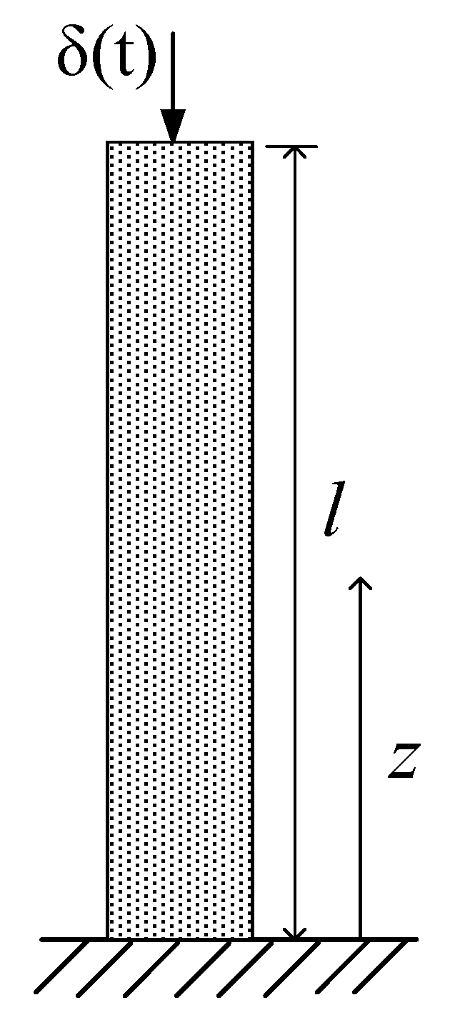
Figure 1 is a schematic of a piezoelectric structure with one end fixed and the other free. The free end of the structure is subjected to an impact load. The height of the structure is
l. Referring to the Cartesian coordinate system, symbols ε, σ,
D and
E denote the strain, stress, induction and electric field, respectively. This paper considers the structure only in one dimension,
i.e., in the
z direction.
For the above structure, according to the model and without the consideration of the body force and body charge, the basic equations for piezoelectric materials can be written as:
It can be known from the basic knowledge of physics that the geometric equation is:
Without external source of electric load, the equation of motion is:
where
and
are coefficients of the piezoelectric and dielectric impermeability for the 0–3 cement based piezoelectric structure, respectively;
is the density of the piezoelectric material;
is the coefficient of elastic stiffness.
Figure 1.
Schematic of a piezoelectric structure under impact load.
Figure 1.
Schematic of a piezoelectric structure under impact load.
By combining Equations (1)–(3), one obtains:
with
Considering the impact load
(for
t < 0,
f(
t) = 0) and the boundary conditions of the structure, the equations of motion and the definite conditions are assumed to be:
where
is the modulus of elasticity of the material.
3. Analytical Solutions of the Piezoelectric Structure under Impact Load
In this section, the theoretical solutions of the mechanical and electrical fields of the structure will be obtained by utilizing standing wave method and traveling wave method, respectively.
(1) Theoretical solutions following the standing wave method
Firstly, in order to use the standing wave method, the nonhomogeneous condition need to be homogeneously transformed, therefore the solution can be assumed to have the form:
where
Q(
z,
t) satisfies:
Obviously, there are many forms of
Q(
z,
t) satisfying Equation (8). Here,
Q(
z,
t) is chosen to have the form:
Moreover, attention should be paid that
Q(
z,
t) = 0 when
z <
l, and
U(
z,
t) =
u(
z,
t) when
. Therefore, the substitution of Equation (7) into Equation (6) gives:
If Equation (10) is a homogeneous equation, the natural frequency of the above equations can be readily obtained to be:
and the corresponding normal modes are:
If Equation (10) is a nonhomogeneous equation, it can be assumed that:
By substituting Equation (13) into the first equation of Equation (10), one obtains:
Meanwhile, the substitution of the second equation of Equation (10) into Equation (13) results in the initial condition of
Tn:
and an algebraic equation about
can be obtained by the Laplace transform:
If ƒ(
t) = δ(
t) (the free end of the structure is under an impact load
), it can be readily obtained from the Laplace transform table:
Therefore, the exact solution of the displacement of the piezoelectric structure under impact load can be obtained as:
where
Using the boundary condition of the free end, the exact solutions of the mechanical and electrical quantities of the piezoelectric structure under impact load are obtained as follows:
Electric field intensity:
Up to now, the exact mechanical and electrical fields of the piezoelectric structure under the impact load have been fully determined by the standing wave method.
(2) Theoretical solutions following the traveling wave method
By utilizing the method for solving the semi-unbounded domain wave equation, the solution of Equation (6) can be obtained as:
where
H(…) is the Heaviside step function.
For the structure under consideration, waves obtained by Equation (25) will be reflected at the fixed end (
z = 0). The reflection coefficient of displacement wave at the fixed end is −1, so displacement of particles in the structure becomes zero after a reflected wave. The reflection coefficient of the displacement wave at the free end is 1, because the reflection occurs again when the reflected wave reaches the free end (
z = 1). Therefore, the elastic waves are reflected back and forth between the two ends, and the expression of the displacement has the form:
which can be simplified to:
Here, the exact displacement of the piezoelectric structure under the impact load has been obtained by the travelling wave method.
4. Numerical Analysis
Traditional piezoelectric structure has poor compatibility with cement structure, therefore limiting its precision in the application of real time monitoring of airport pavement. In contrast, piezoelectric composite structures such as the cement-based smart structure have found more and more applications due to their good compatibility. The solutions obtained in the previous section could be used with 0–3 cement-based piezoelectric composite structure. Based on the schematic and data of Li’s experiment [
28], we assume the following parameter values for the 0–3 cement based piezoelectric structure:
(thickness),
,
,
,
(
is the vacuum dielectric constant). ANSYS is used for the numerical simulation, where an analytical model of the size 4 mm × 4 mm × 40 mm is considered. The direction of the polarization is along
Z-axis. The unit partition of the model is divided into 12 segments along
X-axis and
Y-axis, and 10 segments along
Z-axis. Detailed form of the load is shown in
Figure 2. Here, two types of triangular and step load forms are assumed for the simulation.
Figure 2.
Schematic of the triangular load (a) and the step load (b).
Figure 2.
Schematic of the triangular load (a) and the step load (b).
(1) Comparisons between the standing wave and traveling wave methods
The displacements at the free end and the midpoint are shown in
Figure 3 and
Figure 4, respectively, with different
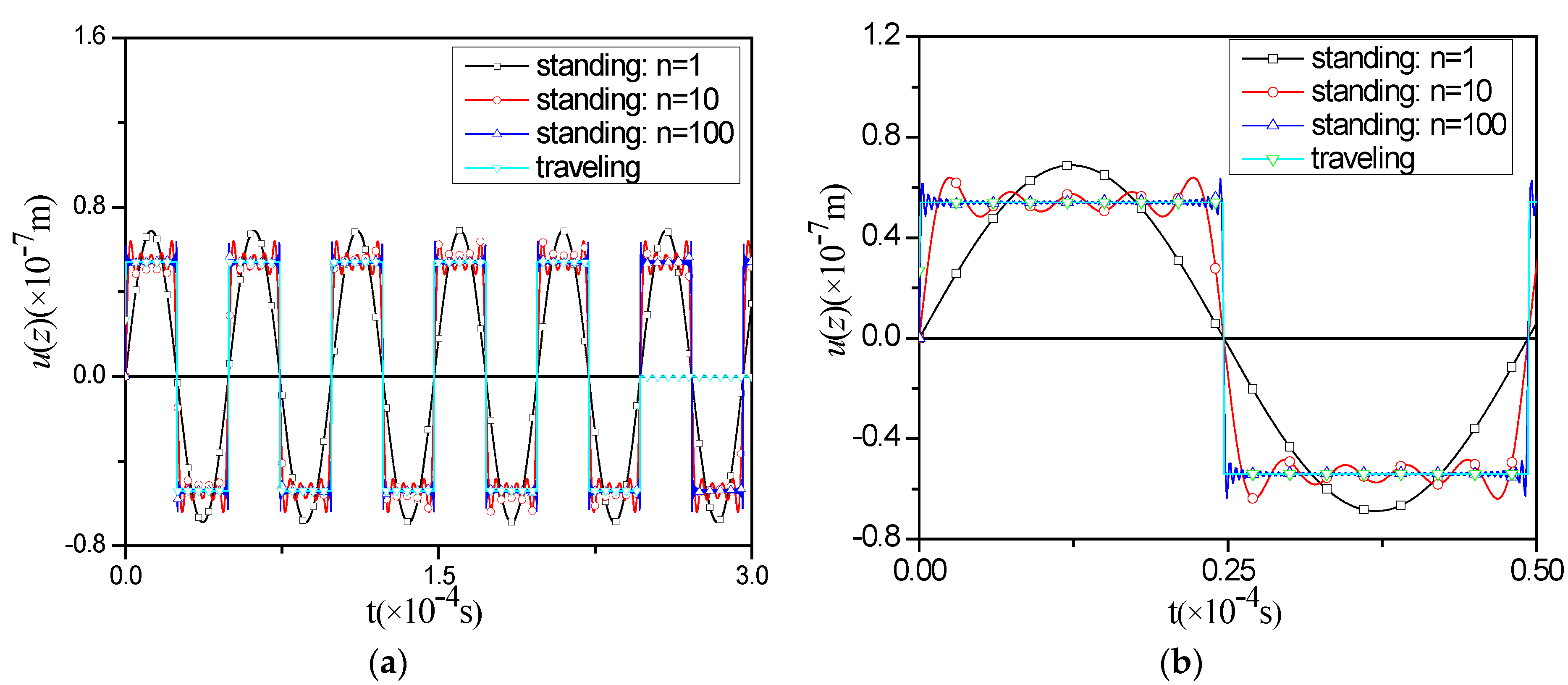
nmax values. The convergence of the traveling wave method is faster than that the standing wave method, indicating that the former is more suitable for simulating the short-term response of the model under investigation. However, the traveling wave method also has limitations. The displacement of the structure obtained by the traveling wave method remains zero when
t is greater than about 2.4 × 10
−4 s. The reason is that by definition the Heaviside step function
H(0) equals 0.5. From this point of view, it is better to use the standing wave method to study the response after a long time since the beginning of the impact load. Moreover, it can be seen that the convergence of the exact solutions following the standing wave method becomes better as
nmax increases.
Figure 3.
Comparisons of the vertical displacement u(z) at the free end between standing wave method and traveling wave method in (a) and (b).
Figure 3.
Comparisons of the vertical displacement u(z) at the free end between standing wave method and traveling wave method in (a) and (b).
Figure 4.
Comparisons of the vertical displacement u(z) at the midpoint between standing wave method and traveling wave method in (a) and (b).
Figure 4.
Comparisons of the vertical displacement u(z) at the midpoint between standing wave method and traveling wave method in (a) and (b).
Furthermore, for this model, a balance position exists for each point. The central point is the balance position of the center-of-mass vibration of the model.
(2) Comparison between results following the standing wave method and the numerical results.
The influences of the impact load on the displacement
u(
z) at the free end in case of the two types of triangular and step load forms are shown in
Figure 5 and
Figure 6, respectively. Good agreements between theoretical and numerical results are found. Although the lasting time and magnitude of the impact load are different, the total impact energy remains the same, therefore the magnitude of the free end displacement
u(
z) keeps unchanged. To be brief and clear, the following numerical results in
Figure 7,
Figure 8 and
Figure 9 are obtained under the triangular impact load of 200 kpa.
Figure 5.
Influence of the load on displacement u(z) at the free end with triangular load.
Figure 5.
Influence of the load on displacement u(z) at the free end with triangular load.
Figure 6.
Influence of load on displacement u(z) at the free end with step load.
Figure 6.
Influence of load on displacement u(z) at the free end with step load.
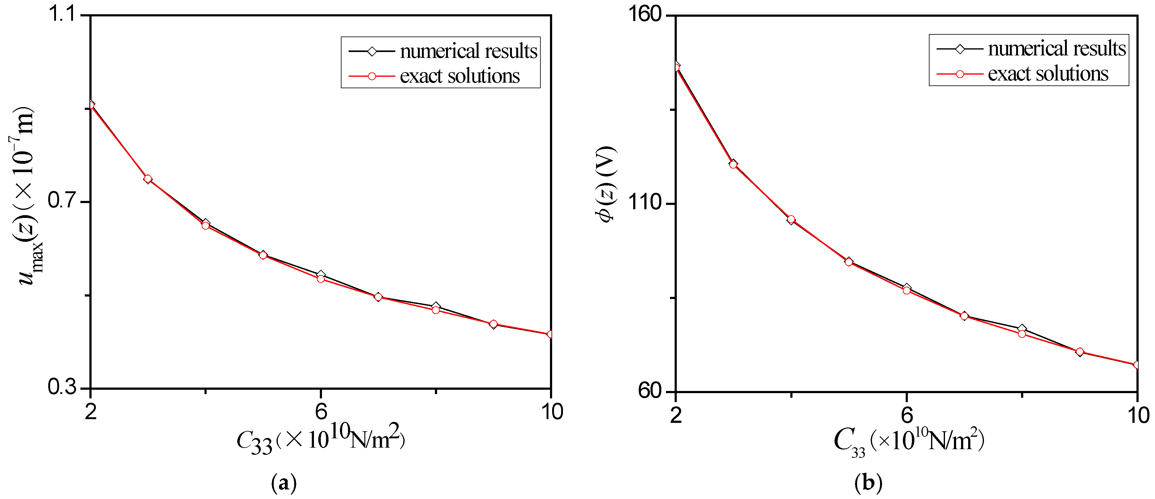
Figure 7.
Influence of on the displacement amplitude umax(z) (a) and the electric potential amplitude (b) at the free end under impact load.
Figure 7.
Influence of on the displacement amplitude umax(z) (a) and the electric potential amplitude (b) at the free end under impact load.
Figure 8.
Influence of on the displacement amplitude umax(z) (a) and the electric potential amplitude (b) at the free end under impact load.
Figure 8.
Influence of on the displacement amplitude umax(z) (a) and the electric potential amplitude (b) at the free end under impact load.
Figure 9.
Influence of on the displacement amplitude umax(z) (a) and the electric potential the amplitude (b) at the free end under impact load.
Figure 9.
Influence of on the displacement amplitude umax(z) (a) and the electric potential the amplitude (b) at the free end under impact load.
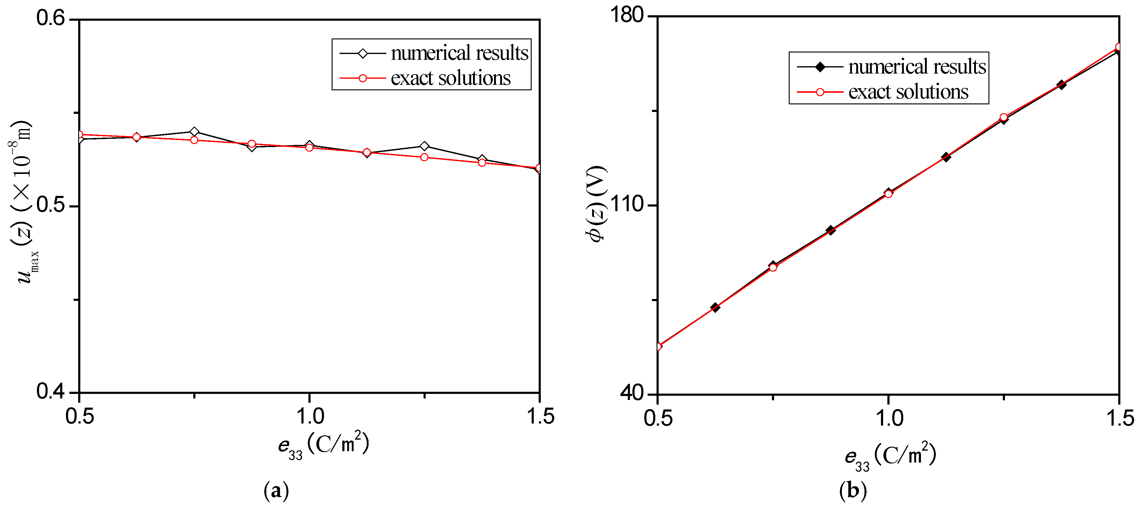
Figure 7a,b shows how the displacement amplitude
umax(
z) and the electric potential amplitude
change with the coefficient of the elastic stiffness
, respectively. It can be found that the displacement amplitude
umax(
z) and the electric potential amplitude
decrease as
increases. Besides, with the increasing of
, the changes of both the displacement amplitude and electric potential amplitude become flatter. The influences of the piezoelectric stress constant
on
umax(
z) and
of the free end are shown in
Figure 8a,b. It can be seen that
umax(
z) decreases with
, but changes quite slowly in
Figure 8a, while
increases almost linearly with
in
Figure 8b. Moreover, the two figures show that
has larger influence on
, providing the guidance for the desired larger electric potential.
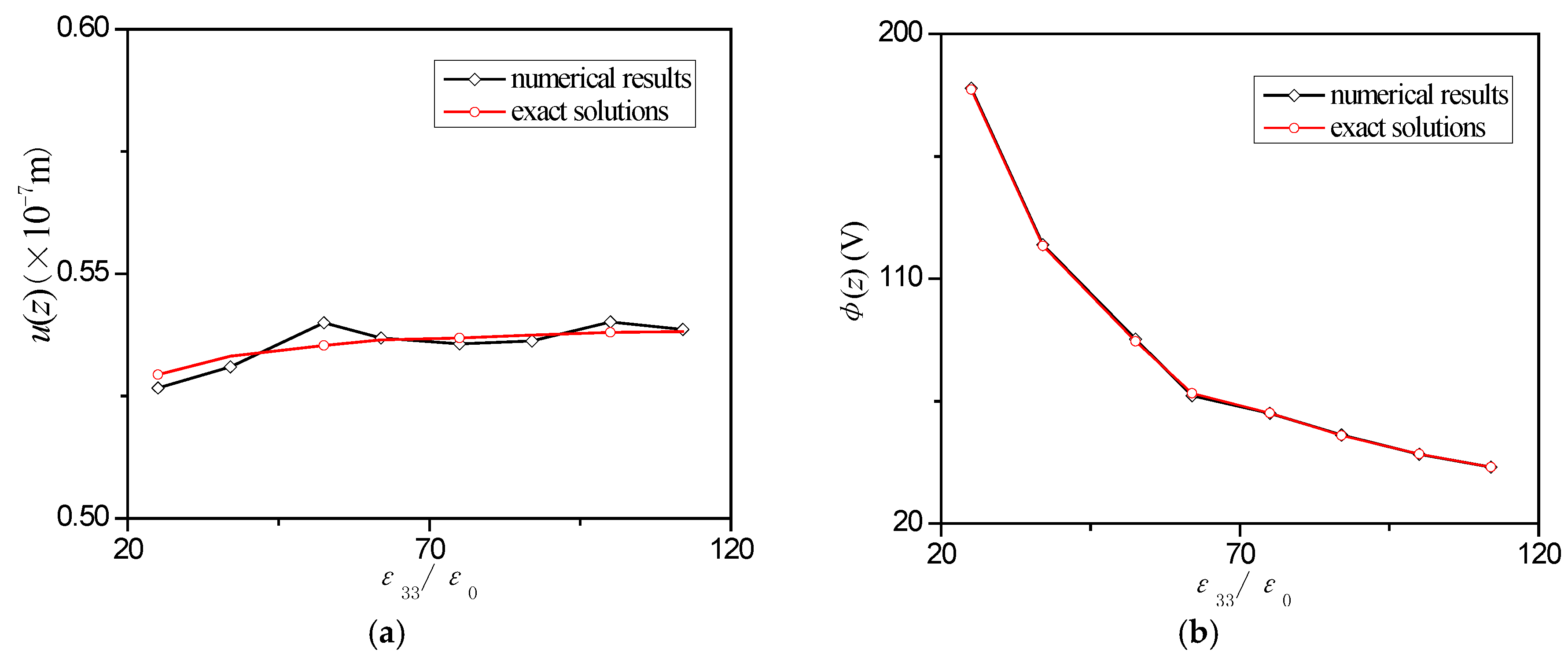
Figure 9a,b shows the influence of the relative dielectric constant
on
umax(
z) and
at the free end under the impact load. It can be seen that
umax(
z) increases quite slowly, while
decreases faster as
increases. Furthermore, it can be noticed that
has larger influence on
.
Figure 7,
Figure 8 and
Figure 9 can be for study of the influence of different parameters on the mechanical and electrical behaviors of this structure, and the guiding role of these parameters in the configuration of the devices. For example, the displacement for this kind of devices used for some sensors might be large enough. Therefore, one could be referenced to the influence given by the theory on the displacement, and as a result piezoelectric material that could provide larger displacement could be selected.
5. Conclusions
The paper established an analytical model of the dynamic properties of a piezoelectric structure under impact load. The theoretical solutions are obtained by using the standing wave method and the traveling wave method, respectively. The results indicate:
(1) Although we applied two approaches to obtain the solutions, they should be mathematically equivalent but attention should be paid when applied for different situations. For studying short time response of piezoelectric bar under impact load, the convergence of the traveling wave method solution is fast. On the other hand, the always existing damping in realistic material increases as the frequency increases. Therefore, the standing wave method solution is better due to the fast attenuation of high-frequency terms. In this case, the lowest frequency term and next few terms would be enough.
(2) The trend of the displacement as a function of t approximates a rectangular wave; and the magnitude of the impact load has weak influence on the displacement of the structure along the axial direction.
(3) The coefficient has obvious influence on both and umax(z); while and have larger influence on than umax(z) in the structure. By selecting different piezoelectric materials, one could obtain experimentally the piezoelectric structures with different mechanical and electrical components, therefore satisfying different applications. Furthermore, this characteristics may benefit the collection of the electric potential.
Moreover, the obtained analytical solutions can provide some guidance for the design of the piezoelectric smart devices under impact load, which would benefit the application in the airplane take-off and landing safety by monitoring the deformation of the runway in real time. The research of the piezoelectric structure has been attracting more and more attentions and needs further investigations. Among others, the study of the piezoelectric structure is of special importance for the application of the piezoelectric device in civil engineering.

