
A Surface Micromachined CMOS MEMS Humidity Sensor


Key Laboratory of MEMS of the Ministry of Education, Southeast University, Nanjing 210096, China
*
Author to whom correspondence should be addressed.
Micromachines 2015, 6(10), 1569-1576; https://doi.org/10.3390/mi6101440
Submission received: 31 August 2015
/
Revised: 24 September 2015
/
Accepted: 12 October 2015
/
Published: 16 October 2015
(This article belongs to the Special Issue CMOS-MEMS Sensors and Devices)
Abstract
:This paper reports a CMOS MEMS (complementary metal oxide semiconductor micro electromechanical system) piezoresistive humidity sensor fabricated by a surface micromachining process. Both pre-CMOS and post-CMOS technologies were used to fabricate the piezoresistive humidity sensor. Compared with a bulk micromachined humidity sensor, the machining precision and the sizes of the surface micromachined humidity sensor were both improved. The package and test systems of the sensor were designed. According to the test results, the sensitivity of the sensor was 7 mV/%RH (relative humidity) and the linearity of the sensor was 1.9% at 20 °C. Both the sensitivity and linearity were not sensitive to the temperature but the curve of the output voltage shifted with the temperature. The hysteresis of the humidity sensor decreased from 3.2% RH to 1.9% RH as the temperature increased from 10 to 40 °C. The recovery time of the sensor was 85 s at room temperature (25 °C).
1. Introduction
Electrical humidity sensors date back to the first electrolytic humidity sensor reported in 1938 [1]. Nowadays, humidity sensors have been widely used in many kinds of electrical systems such as industrial monitoring systems, agricultural monitoring systems, weather systems, medical equipment, household appliances, and so on [2,3,4]. Owing to the development of micromachining technology, both the sizes and the performances of the sensors were improved while the costs become much lower [5].
Today the most popular commercial humidity sensors are resistive humidity sensors and capacitive humidity sensors. Although the resistive humidity sensors are easily fabricated and the readout circuits are simple, the drawbacks of long recovery time and low stability limit their applications [2,3]. The capacitive humidity sensors offer several advantages such as low power consumption, wide temperature range, and long-term stability, but the readout circuits may be complex for high precision applications [6,7].
In both resistive humidity sensors and capacitive humidity sensors, the performances of a sensor are directly affected by the electrical characteristics of a sensitive material. This usually leads to a nonlinear property of the sensor at low relative humidity (typically for a resistive sensor [2,8]) or high relative humidity (typically for a capacitive humidity [9,10]). To solve this problem, we can separate the sensitive material into a humidity-sensitive material and a mechanical-sensitive material, which promote the study of a piezoresistive humidity sensor.
Figure 1 depicts the operation principle of a piezoresistive humidity sensor. The sensor utilizes the expansion of the humidity-sensitive material due to the uptake of water molecules. The expansion leads to a stress change in the structure and the piezoresistor (a mechanical sensitive element) transforms the stress change into an electrical signal. The piezoresistive humidity sensors have the advantages of high linearity, long-term stability, and simple readout circuit. The major problem of the piezoresistive humidity sensor is the temperature drift, but it can be compensated by a circuit.
Figure 1.
Schematic of a microcantilever piezoresistive humidity sensor: (a) The shape of the microcantilever before uptake of water molecules; (b) After uptake of water molecules.
Figure 1.
Schematic of a microcantilever piezoresistive humidity sensor: (a) The shape of the microcantilever before uptake of water molecules; (b) After uptake of water molecules.

Usually, a bulk micromachining process was used to fabricate a piezoresistive humidity sensor [11,12,13,14]. However, the machining precision was always limited by the bulk wet etching process and some chip area was wasted because of a large pattern on the backside of the wafer [15]. Alternatively, the bulk wet etching process can be replaced by a deep reactive ion etching process, but a dual side fabrication process always leads to additional machining errors. To solve these problems, a surface machined microcantilever piezoresistive humidity sensor was developed in this paper. The fabrication process of the sensor was CMOS compatible. Both pre-CMOS machining and post-CMOS machining were carried out to fabricate the sensitive structure. Additionally, single-crystal silicon was used as the mechanical-sensitive material (piezoresistive material) so that both good mechanical and electrical properties were achieved.
2. Experimental Section
2.1. Fabrication of the Humidity Sensor
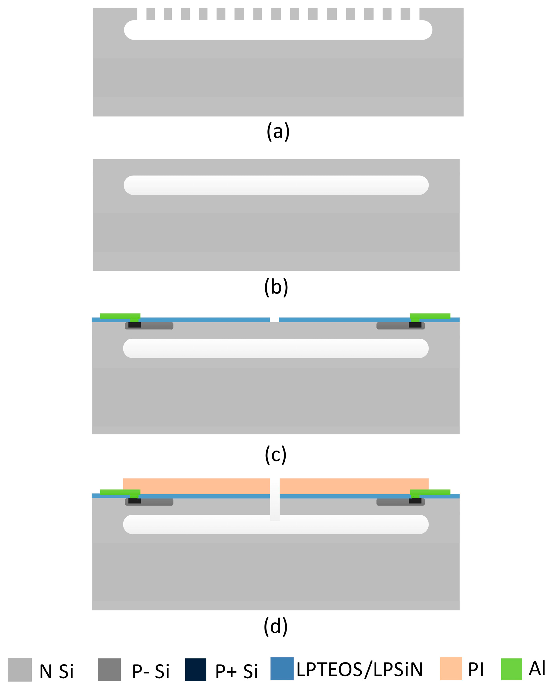
Figure 2 illustrates the fabrication process of the microcantilever piezoresistive humidity sensor. Fabrication started with an N type (100) wafer. Before the CMOS process, a two-step etching process was performed as shown in Figure 2a. First, an array of grooves was fabricated by anisotropic dry etching. Next, a cavity was fabricated by isotropic dry etching below the grooves. Then the cavity was sealed by an epitaxial growth process as shown in Figure 2b. As follows, a typical CMOS process was used to form piezoresistors, dielectric and metal wires, as shown in Figure 2c. In the CMOS process, ion-implanted p-type resistors with a sheet resistance of 400 Ω/sq and a junction depth of 1 μm were fabricated as the piezoresistors. The resistance of each piezoresistor was 3.2 kΩ. After the CMOS process, a polyimide layer was spun on the wafer with a speed of 3000 rad/min and patterned to form the humidity-sensitive material. The polyimide was cured in a nitrogen atmosphere with a three-step heating process (150 °C for 1 h, 250 °C for 1 h and 300 °C for 1 h; the heating rate was 4 °C/min from room temperature to 150 °C, 3 °C/min from 150 to 250 °C and 1.6 °C/min from 250 to 300 °C, respectively). Lastly, an anisotropic dry etching process was used to release the microcantilevers (Figure 2d). Table 1 shows some details of the materials and fabrication process.
Figure 3 shows the SEM (scanning electron microscope) image of the microcantilever piezoresistive humidity sensor. As shown in Figure 3a, four cantilevers were fabricated in the sensor. The piezoresistors located near the fix end of the cantilevers were connected as a Wheatstone bridge. The size of the cantilevers was 400 μm wide by 100 μm long. There are two advantages to fabricating such short cantilevers: First, the sensitivity of the sensor was increased with the stress optimization [16]; Second, the reliability was improved with a robust structure.
Figure 2.
Fabrication process of the microcantilever piezoresistive humidity sensor: (a,b) Pre-process of the substrate; (c) Structure after CMOS (complementary metal oxide semiconductor) process; (d) Structure after post-process.
Figure 2.
Fabrication process of the microcantilever piezoresistive humidity sensor: (a,b) Pre-process of the substrate; (c) Structure after CMOS (complementary metal oxide semiconductor) process; (d) Structure after post-process.


| Layer | Material | Thickness (μm) |
|---|---|---|
| epitaxial layer | single crystal silicon | 8 |
| dielectric | TEOS (tetraethoxysilane)/SiN (silicon nitride) | 0.3/0.1 |
| metal | AlCu | 1.9 |
| humidity sensitive material | Polyimide (PI) | 3 |
Figure 3.
SEM (scanning electron microscope) image of the microcantilever piezoresistive humidity sensor: (a) Front view of the micromachined structure; (b) Details at the center of the structure.
Figure 3.
SEM (scanning electron microscope) image of the microcantilever piezoresistive humidity sensor: (a) Front view of the micromachined structure; (b) Details at the center of the structure.
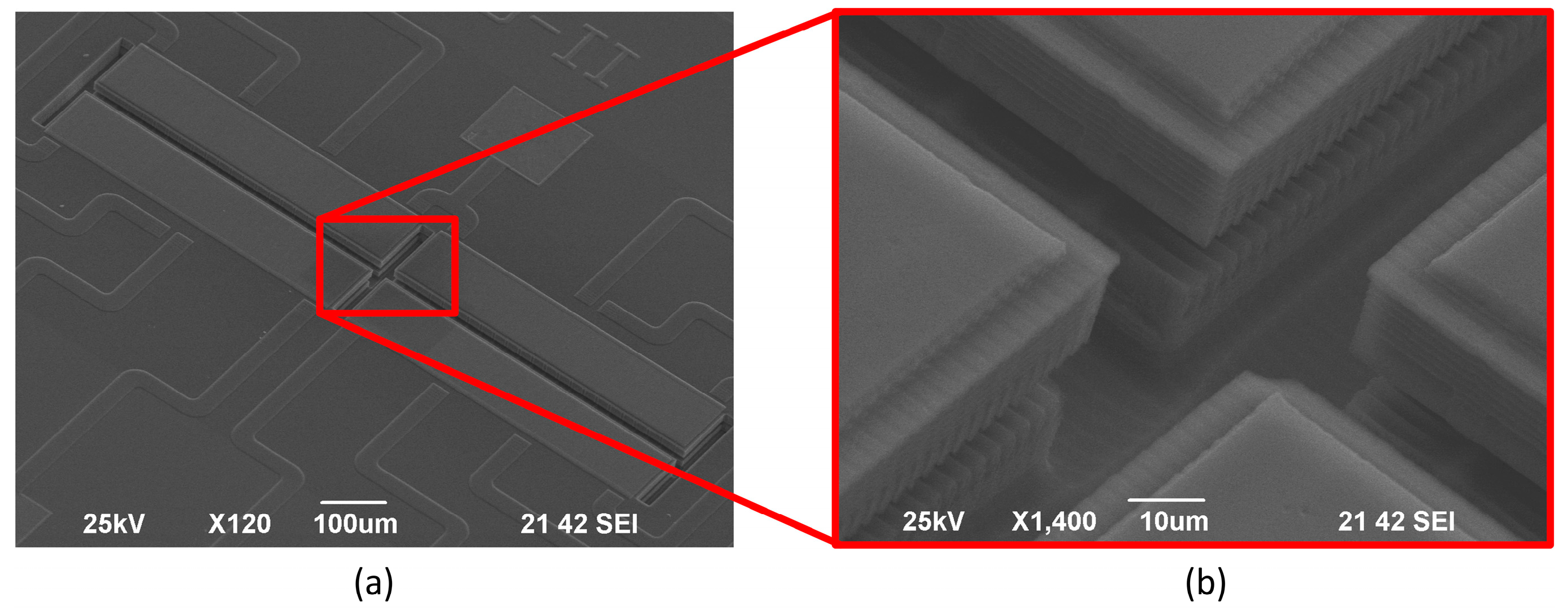
Figure 3b shows the details of the cantilevers. It can be seen that a network of ripples distributed on the cantilever. The ripples resulted from the grooves fabricated at the first step, as shown in Figure 2a. In this paper, the depth of the grooves was 5 μm and the thickness of the epitaxial layer was 8 μm so that the average thickness of the silicon layer in the cantilevers was about 10.5 μm. Although uniform grooves were used in the paper, the shapes and distributions of the grooves can be designed to achieve a stress concentrated structure in the future.
2.2. Package of the Humidity Sensor
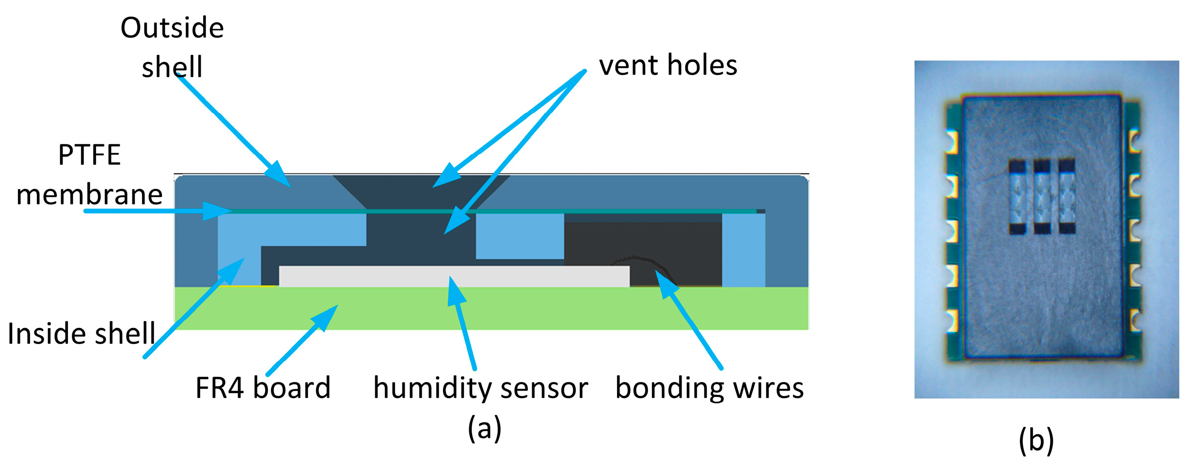
Figure 4 depicts the package of the humidity sensor. As shown in Figure 4a, an FR4 board (a kind of printed circuit board) was used as the substrate of the package. The humidity sensor was fixed on the FR4 board, wire-bonded, and covered with two shells. A hydrophobic porous polytetrafluoroethylene (PTFE) membrane with good humidity penetration was sandwiched between the two shells to protect the sensor from contamination of dust and other chemicals. Some vent holes were designed on both shells to guarantee the humidity exchange between the sensitive material and the outside atmosphere through the PTFE membrane. A photograph of the packaged humidity sensor is shown in Figure 4b.
Figure 4.
Package of the microcantilever piezoresistive humidity sensor: (a) Schematic illustration of a cross-sectional view of the package structure; (b) Photograph of the package.
Figure 4.
Package of the microcantilever piezoresistive humidity sensor: (a) Schematic illustration of a cross-sectional view of the package structure; (b) Photograph of the package.

3. Results and Discussion
To characterize the microcantilever piezoresistive humidity sensor, both static and transient responses were tested. A typical Wheatstone bridge circuit was developed to transform the change of the piezoresistance into an output voltage. In the circuit, the bridge excitation current is 0.6 mA and the output voltage was amplified 100 times by an amplifier module.
3.1. Static Responses of Humidity Sensor
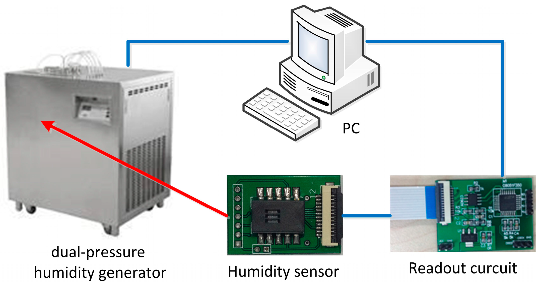
The static responses of the micorcantilever piezoresistive humidity sensor were tested by the system descripted in Figure 5. A dual-pressure humidity generator was used to provide a stable humidity atmosphere at a fixed temperature. The packaged humidity sensor was put into the test chamber of the dual-pressure humidity generator and connected to the Wheatstone bridge readout circuit. The humidity and the temperature in the test chamber were controlled by a computer and the output voltage data were recorded by the computer as well.
Figure 5.
The system for static measurement of the humidity sensor.

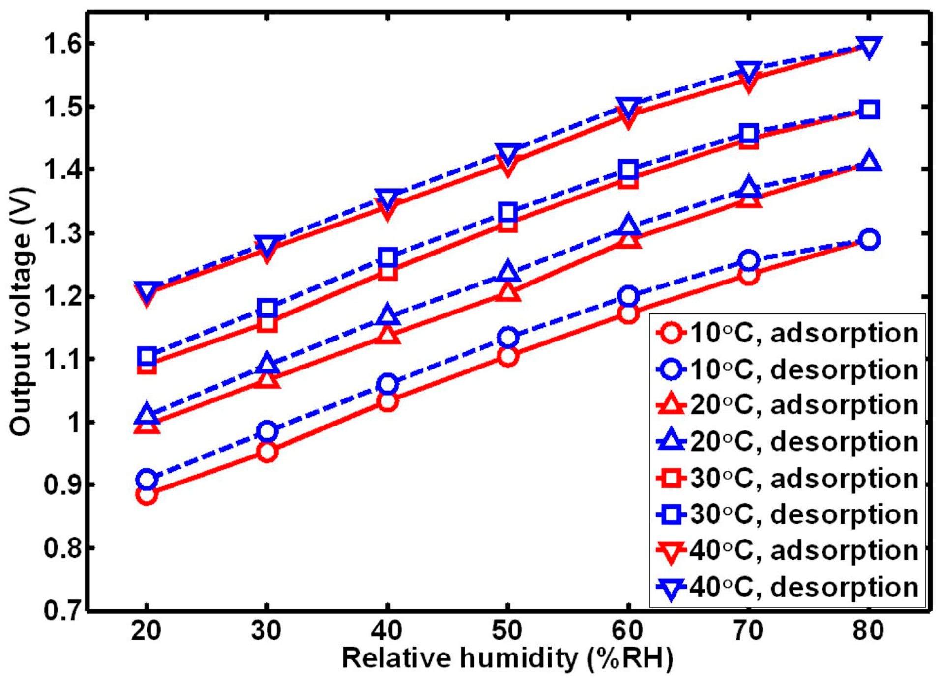
Figure 6 shows the relationship between the output voltage of the microcantilever piezoresistive humidity sensor and the relative humidity. The humidity sensor was tested at 20%, 40%, 60% and 80% relative humidity when the temperature was controlled at 10, 20, 30 and 40 °C. Both the adsorption and desorption processes were carried out. According to the test results, the output voltage changed monotonically with the relative humidity and the sensitivity of the humidity sensor decreased slightly with the relative humidity. Both the sensitivity and the linearity of the humidity sensor changed little with the temperature. At 20 °C, the sensitivity of the sensor was 7 mV/%RH and the linearity of the sensor was 1.9%. The hysteresis property of the humidity sensor was improved by a higher temperature because the diffusion of the water vapor was promoted. Although the sensitivity of the humidity sensor was barely affected by the temperature, the curves of the output voltage shifted with the temperature due to both the thermal stresses in the composite beam and the leakage current across the piezoresistor-substrate p-n junction. The leakage current across the p-n junction is defined as the reverse current which contributes to the thermal drift of the bridge offset voltage as well [17]. As in all kinds of piezoresistive sensors, the thermal drift is a major problem of the microcantilever piezoresistive humidity sensor. A temperature sensor (for instance, a thermal resistor) fabricated near the humidity sensor and a circuit should be used to compensate for the thermal drift. According to the characteristics of the curves as shown in Figure 6, the thermal drift can be simply compensated by an offset voltage which is determined by the temperature sensor.
Figure 6.
Relationship between the output voltage of the sensor and the relative humidity at different temperatures.
Figure 6.
Relationship between the output voltage of the sensor and the relative humidity at different temperatures.

To characterize the accuracy of the sensor, the microcantilever piezoresistive humidity sensor was calibrated at 20 °C. A precision dew-point hygrometer was used as a measurement standard. According to the test results, the maximum error of the microcantilever piezoresistive humidity sensor was 1.8% RH and the uncertainty of the measurement results was 1.2% RH for repeated measurements.
3.2. Transient Response of Humidity Sensor
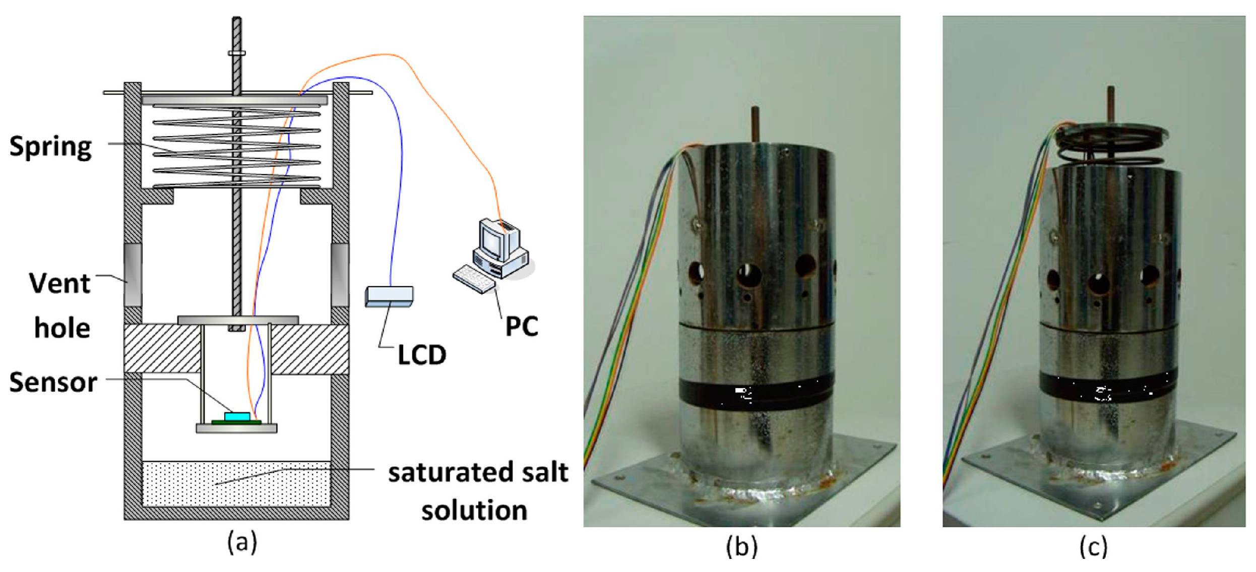
To test the transient response of the microcantilever piezoresistive humidity sensor, equipment was developed as shown in Figure 7. There were two chambers in the equipment: the upper chamber was connected to the outside atmosphere via several vent holes; the lower chamber was sealed where the atmosphere of the humidity was produced by a saturated salt solution. First, the humidity sensor was sealed in the lower chamber. The test data of the sensor were read out by an LCD (liquid crystal display). After the output stable state was obtained, the sensor was quickly pulled up by a spring and a humidity step was achieved. In this process, the output data of the sensor were recorded by a computer and used to evaluate the transient property of the sensor later.
Figure 7.
Test equipment used for transient measurement: (a) Operation principle of the equipment; (b) Photograph of the equipment as the sensor sealed in the lower chamber; (c) Photograph of the equipment as the sensor pulled up.
Figure 7.
Test equipment used for transient measurement: (a) Operation principle of the equipment; (b) Photograph of the equipment as the sensor sealed in the lower chamber; (c) Photograph of the equipment as the sensor pulled up.

It is well known that a desorption process is always slower than an adsorption process. To evaluate the transient property of the sensor, a step response experiment was carried out for a desorption process. In the experiment, a K2SO4 saturated salt solution was used to provide 97% relative humidity in the lower chamber and the humidity outside was 67% RH, so the humidity step was from 97% RH to 67% RH.
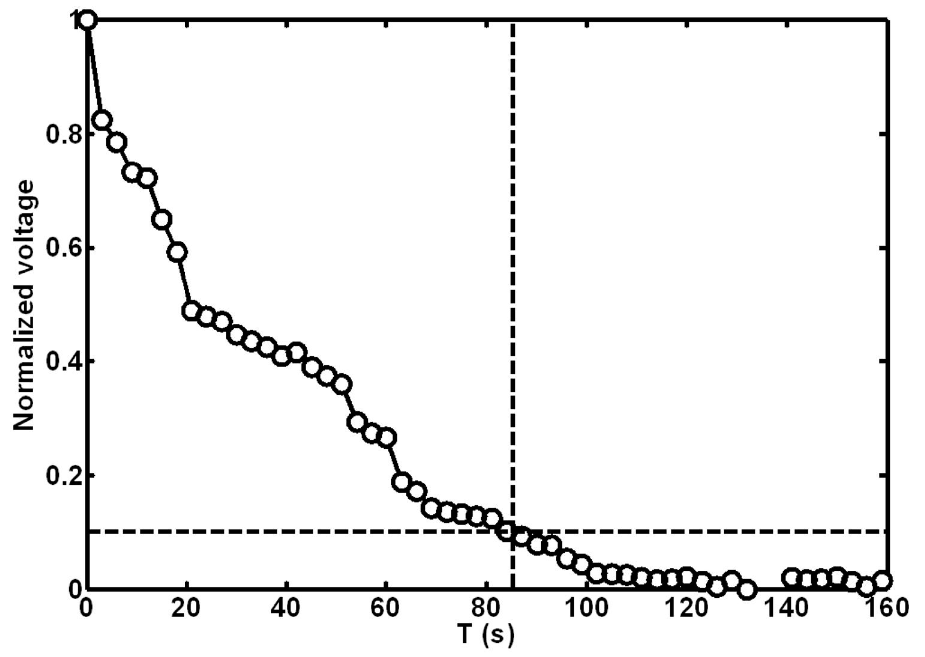
The recovery time is an important parameter of the humidity sensor. It is defined as the time for the output to reach 90% of its final value as the humidity step drops. As shown in Figure 8, the recovery time of the microcantilever piezoresistive humidity sensor was 85 s at room temperature (25 °C). In Figure 8, there were some fluctuations in the curve. The fluctuations may have resulted from the shock of the sensor in the pull-up process. To improve the transient property of the sensor, a thinner humidity-sensitive layer could be applied, but the sensitivity of the sensor will be degraded at the same time, so a tradeoff between the time constant and the sensitivity is needed.
Figure 8.
Transient response of the humidity sensor.
4. Conclusions
A microcantilever piezoresistive humidity sensor was presented in this paper. The sensor was surface micromachining fabricated by a CMOS MEMS process. Both pre-CMOS technology and post-CMOS technology were used in the fabrication process. Compared with a bulk fabricated microcantilever piezoresistive humidity sensor, the machining precision was improved and the structure was more compact.
A package of the humidity sensor was designed and fabricated. To characterize the performance of the humidity sensor, both static and transient tests were performed. According to the test results, the sensitivity of the sensor was 7 mV/%RH and the linearity of the sensor was 1.9% at 20 °C. Both the sensitivity and linearity were not sensitive to the temperature. However, the hysteresis of the humidity sensor decreased from 3.2% RH to 1.9% RH as the temperature increased from 10 to 40 °C. The recovery time of the sensor was 85 s at room temperature (25 °C).
Because of thermal stresses, the curve of the output voltage shifted with the temperature. The work in the future will focus on the temperature drift compensation and stress optimization of the structure.
Acknowledgments
The project is supported by the National Natural Science Foundation of China under contract No. 61302021.
Author Contributions
Jian-Qiu Huang designed the sensor and the test systems, and also prepared and approved the manuscript. Fei Li, Min Zhao and Kai Wang carried out the package and test experiments. All authors reviewed the manuscript.
Conflicts of Interest
The authors declare no conflict of interest.
References
- Dunmore, F.W. An electric hygrometer and its application to radio meteorography. J. Res. Natl. Bur. Stand. 1938, 20, 723–744. [Google Scholar] [CrossRef]
- Farhani, H.; Wagiran, R.; Hamidon, M.N. Humidity sensors principle, mechanism and fabrication technologies: A comprehensive review. Sensors 2014, 14, 7881–7939. [Google Scholar] [CrossRef] [PubMed]
- Lee, C.-Y.; Lee, G.-B. Humidity sensors: A review. Sens. Lett. 2005, 3, 1–14. [Google Scholar] [CrossRef]
- Stanislav, A.K.; Neil, T.G.; Chengbo, M.; Kaiming, Z. Toward a new generation of photonic humidity sensors. Sensors 2014, 14, 3986–4013. [Google Scholar]
- Hierlemann, A.; Brand, O.; Hagleitner, C.; Baltes, H. Microfabrication techniques for chemical/biosensors. Proc. IEEE. 2003, 91, 839–863. [Google Scholar] [CrossRef]
- Chen, Z.; Lu, C. Humidity sensors: A review of materials and mechanisms. Sens. Lett. 2005, 3, 274–295. [Google Scholar] [CrossRef]
- Fenner, R.; Zdankiewicz, E. Micromachined water vapor sensors: A review of sensing technologies. IEEE Sens. J. 2001, 1, 309–317. [Google Scholar] [CrossRef]
- Li, Y.; Hong, L.; Chen, Y.; Wang, H.; Lu, X.; Yang, M. Poly(4-Vinylpyridine)/carbon black composite as a humidity sensor. Sens. Actuators B Chem. 2007, 123, 554–559. [Google Scholar] [CrossRef]
- Kim, Y.; Jung, B.; Lee, H.; Kim, H.; Lee, K.; Park, H. Capacitive humidity sensor design based on anodic aluminum oxide. Sens. Actuators B Chem. 2009, 141, 441–446. [Google Scholar] [CrossRef]
- Wang, Y.; Park, S.; Yeow, J.T.W.; Langner, A.; Müller, F. A capacitive humidity sensor based on ordered macroporous silicon with thin film surface coating. Sens. Actuators B Chem. 2010, 149, 136–142. [Google Scholar] [CrossRef]
- Guo, H.; Lou, L.; Chen, X.; Lee, C. PDMS-coated piezoresistive NEMS diaphragm for chloroform vapor detection. IEEE Electron Device Lett. 2012, 33, 1078–1080. [Google Scholar] [CrossRef]
- Buchhold, R.; Nakladal, A.; Gerlach, G.; Neumann, P. Design studies on piezoresistive humidity sensors. Sens. Actuators B Chem. 1998, 53, 1–7. [Google Scholar] [CrossRef]
- Gerlach, G.; Sager, K. A piezoresistive humidity sensor. Sens. Actuators A Phys. 1994, 43, 181–184. [Google Scholar] [CrossRef]
- A Comparison of Relative Humidity Sensing Technologies. Available online: http://pasternack.ucdavis.edu/files/6213/7271/8210/hyd151_read13.pdf (accessed on 14 October 2015).
- Madou, M.J. Wet Bulk Micromachining. In Fundamentals of Microfabrication, 2nd ed.; Madou, M., Gottehrer, P., Eds.; CRC Press: Boca Raton, FL, USA, 2000; pp. 199–205. [Google Scholar]
- Park, S.-J.; Doll, J.C.; Rastegar, A.J.; Pruitt, B.L. Piezoresistive cantilever performance—Part II: Optimization. J. Microelectromech. Syst. 2010, 19, 149–161. [Google Scholar] [CrossRef] [PubMed]
- Pruitt, L. Review: Semiconductor piezoresistance for microsystems. Proc. IEEE. 2009, 97, 513–552. [Google Scholar]
© 2015 by the authors; licensee MDPI, Basel, Switzerland. This article is an open access article distributed under the terms and conditions of the Creative Commons by Attribution (CC-BY) license (http://creativecommons.org/licenses/by/4.0/).
Share and Cite
MDPI and ACS Style
Huang, J.-Q.; Li, F.; Zhao, M.; Wang, K. A Surface Micromachined CMOS MEMS Humidity Sensor. Micromachines 2015, 6, 1569-1576. https://doi.org/10.3390/mi6101440
AMA Style
Huang J-Q, Li F, Zhao M, Wang K. A Surface Micromachined CMOS MEMS Humidity Sensor. Micromachines. 2015; 6(10):1569-1576. https://doi.org/10.3390/mi6101440
Chicago/Turabian StyleHuang, Jian-Qiu, Fei Li, Min Zhao, and Kai Wang. 2015. "A Surface Micromachined CMOS MEMS Humidity Sensor" Micromachines 6, no. 10: 1569-1576. https://doi.org/10.3390/mi6101440