Article

Shielding Electric Fields to Prevent Coalescence of Emulsions in Microfluidic Channels Using a 3D Metallic Coil

1
HKU-Shenzhen Institute of Research and Innovation (HKU-SIRI), Shenzhen 518000, China
2
Department of Mechanical Engineering, University of Hong Kong, Hong Kong, China
*
Author to whom correspondence should be addressed.
Micromachines 2015, 6(10), 1459-1468; https://doi.org/10.3390/mi6101430
Submission received: 14 August 2015 / Revised: 16 September 2015 / Accepted: 23 September 2015 / Published: 30 September 2015
(This article belongs to the Special Issue Droplet Microfluidics: Techniques and Technologies)

Abstract

:
In microfluidics, electric fields are widely used to assist the generation and the manipulation of droplets or jets. However, uncontrolled electric field can disrupt the operation of an integrated microfluidic system, for instance, through undesired coalescence of droplets, undesired changes in the wettability of the channel wall or unexpected death of cells. Therefore, an approach to control the distribution of electric fields inside microfluidic channels is needed. Inspired by the electro-magnetic shielding effect in electrical and radiation systems, we demonstrate the shielding of electric fields by incorporating 3D metallic coils in microfluidic devices. Using the degree of coalescence of emulsion drops as an indicator, we have shown that electric fields decrease dramatically in micro-channels surrounded by these conductive metallic coils both experimentally and numerically. Our work illustrates an approach to distribute electric fields in integrated microfluidic networks by selectively installing metallic coils or electrodes, and represents a significant step towards large-scale electro-microfluidic systems.

Graphical Abstract

1. Introduction

Electric fields are frequently used in droplet-based microfluidics to assist the droplet generation and manipulation [1–3]. The application of electric fields can alter the stability of interfaces between immiscible fluids. In an electric field, the interfaces of fluids are polarized or charged. These charged interfaces experience an electric stress, which is quantified as the multiplication of an electric field’s strength, E, by electric charges, Q: FE = E · Q. Such electric stress tends to deform the liquid interface against interfacial tension, γ , which resists the deformation. The competition between the two stresses can be characterized by the electro-capillary number: C a e = ε 0 ε R E 2   γ , where ε 0 is the vacuum permittivity, ε is the dielectric constant of the liquid, and R is the radius of curvature. When C a e is larger than unity, the electric stress is sufficient to overcome the restoring capillary pressure and deform the liquid interfaces. Consequently, droplet elongation and jet thinning can be more easily achieved, enabling controlled formation of micro- and nano-scaled droplets [4,5] and fibers [6]. Additionally, the electric stress can cause the coalescence of neighboring emulsion droplets [7,8]; this phenomenon is often known as electro-coalescence and is frequently utilized in applications including triggered chemical reaction [9], injection of liquid contents into stabilized droplets [1,10], droplet mixing [3] and characterization of emulsion stability [11].
Despite its usefulness in various applications, an uncontrolled electric field can introduce undesired effects in microfluidics. For instance, electric fields will cause the coalescence of densely packed emulsions in microfluidic devices, which are commonly used for pico-injection of reagents into droplets [10] and for high throughput biological assays [12,13]. An uncontrolled electric field will also change the wettability of a substrate [14,15], leading to unexpected changes in droplet structures and sizes [16,17,18,19]. Additionally, due to its ability to change the permeability of cell membranes [20], the presence of an electric field in undesired parts of a microfluidic process can harm biological cells, or even cause their death [21].
Therefore, it is necessary to precisely control the distribution of electric fields in integrated microfluidic devices. In places where electric fields are needed, the channel design should enable electric field-induced phenomena, such as electro-coalescence; in locations where electric fields are deemed detrimental to the application, novel ways to shield the channel from undesired electric fields are needed.
In this study, we insert segments of a microfluidic channel into a 3D metallic coil to shield the electric field. This is analogous to the electro-magnetic shielding in radiation and electrical systems [21,22] and “Faraday Mote” [23] where an electric field has been shown to be shielded in a space enclosed by a good electrical conductor. In our work, the shielding efficiency is systematically studied by the dynamic behaviors of pairs of droplets under an electric field. Our results demonstrate that the 3D metallic coil can prevent the electro-coalescence of emulsions efficiently and conveniently. In addition, we have confirmed the effectiveness of the coil for reducing electric fields through a numerical simulation using COMSOL. Moreover, we find that the shielding effectiveness increases with increasing number density of the coil. Our approach in shielding electric fields using a 3D metallic coil will provide a simple and effective approach to tailor electric fields in sophisticated and integrated microfluidic devices for droplet-based engineering involving electric fields.

2. Experimental Section

2.1. Device Fabrication and Solution Preparation

We used water with 10 wt % polyethylene glycol (PEG, MW = 8000, Aladdin, Shanghai, China) as the droplet phase and paraffin oil (Aladdin, 36 mPa·s) with 3 wt % EM 90, a non-ionic surfactant, as the continuous phase. The interfacial tension between the droplet phase and the continuous phase is 4.6 ± 0.1 mN/m, as measured by a spinning drop tensiometer (Kruss, SITE100, Hamburg, Germany).
A poly (methyl methacrylate) (PMMA) microfluidic device was fabricated by assembling three layers of PMMA boards. The primary PMMA boards were cut by using a laser-cutting machine (Universal Laser Systems, model VLS2.30, Scottsdale, AZ, USA) with pre-designed micro-channels. This device has two parts. The first part of the device is designed to generate and to store droplets, as shown in Figure 1A. To prepare emulsion droplets with a diameter less than 1.5 mm, approximately equal to the thickness of the PMMA board, a glass capillary (World Precision Instruments, Inc. 1B100F-6, Sarasota, FL, USA) with a tapering tip (diameter is 50 μm) was inserted into the PMMA device to flow the droplet phase, as shown in Figure 1. This tapered glass capillary was achieved by pulling it using a micro-pipet puller (Sutter, P-97, Novato, CA, USA). In the second part of the device, which is used to study the dynamic behaviors of emulsion droplets in an electric field, droplets flowed into an observation channel with a width of 1.5 mm. The schematic of the observation channel is shown in Figure 1B. Points “a”, “b”, “e” and “f” represent the left electrode, inlet of the droplet flow, outlet of the droplet flow and the right electrode respectively. An iron coil, which was prepared by winding an iron wire (wire diameter is (0.125 ± 0.025) mm) around a cylinder with an outer diameter of 1 mm, was inserted into the observation channel with an inlet “c” and outlet “d”. The inlet of the coil is 12 mm away from the left electrode while the outlet of the coil is 19 mm away from the left electrode. To avoid effects due to the edge of the coil, we limited our observation to within the space of the coil that is between 12.5 and 18.5 mm away from the left electrode. An electrical field, E, is established along the observation channel by connecting the two electrodes to a high voltage power supply (Tianjian Dongwen, Tianjian, China). The distance between the two electrodes is 30 mm.
Figure 1. The schematic of the experimental device. (A) Droplet generation and storage; (B) The observation window for studying the emulsion dynamics in an electric field. There are two electrodes on the left and right sides of the observation channel, which are referred to as “a” and “f” in the schematic. Droplets flow from inlet “b” into the observation channel and then leave from outlet “e”. A metallic coil is inserted inside the middle of channel from “c” to “d”. A high voltage is applied to the device by connecting the electrodes to a power supply. dp is the distance between each pitch of the coil; r is the radius of droplets; h is the distance between two droplets.
Micromachines 06 01430 g001

2.2. Experimental Procedure

The droplet phase and the continuous phase were both pumped into the device using syringe pumps (Longer Pump, LSP01-2A, Baoding, China) at controlled flow rates. There were four inlets of liquids, as marked in Figure 1. Inlet 1 was used to pump the droplet phase. The other three inlets were used to pump the continuous phase. During the process of the emulsion generation, only pumps connected with inlets 1 and 2 were opened, resulting in the generation of PEG droplets. Droplet sizes were varied by changing the flow rates. Following droplet generation, pumps for inlets 1 and 2 were stopped, and the formed droplets were stored in the long channels before entering the observation channel. For each observation, only two droplets with the same sizes were injected from the storage channel into the observation channel by opening inlet 2. Inlet 3 and inlet 4 were used to manipulate the position of the droplet pair along the observation channel as well as the distance between them. Before applying an electric field to the microfluidic device, all the pumps were stopped. The velocities of the two droplets were less than 1 mm/min; thus the two droplets were considered not to be moving. We therefore ignored the viscous shear effect of the continuous phase during our experiments considering the capillary number which characterizes the completion between the viscous force and the interfacial tension ( C a = μ v   γ , where μ is the viscosity of the continuous phase and v is the velocity) is less than 1 × 10⁻⁴. Droplet behaviors in an electric field were captured by a high-speed camera (Phantom V9.1, Vision Research, Wayne, NJ, USA) connected to a microscope (Motic, AE2000 Trinocular Inverted Microscope, Xiamen, China). The distance between the two droplets, h, as well as the radius, r, of the droplets were measured using the open-source software Image J. A relative distance, H, which is defined as: H = h r , is used to describe the ratio of distance to its radius. The applied electric field in the microchannel is calculated by dividing the voltage, U, applied across the two electrodes with the separation distance, L, between them:   E =   U L .

3. Numerical Model

The static electric field in the device is simulated using COMSOL (COMSOL Multiphysics 4.3b, Stockholm, Sweden). In the experiment, the length of the channel was 30 mm and the diameter of droplets was less than 0.6 mm. Considering that there were only two droplets in the channel, the dimension ratio between the droplets and channel was less than 4%. Therefore, we ignored the modification of the electrical field caused by the presence of droplets.
A 3D structure of the device was established based on the dimensions of the observation channel, as shown in Figure 2A. Its total length was 30 mm, and two electrodes with 1 mm width and 1.5 mm height were placed at the beginning and the end of the channel, as shown in Figure 2B. 3 layers of PMMA boards enclosed the space of observation channel. The PMMA device was placed in air. The relative permittivity of PMMA and paraffin oil was set to be 4.9 [24] and 2.2 [25] respectively. The negative real relative permittivity of the iron was on the order of 104 [26]. The electrical conductivity values of PMMA, paraffin oil, and iron were set as 3 × 10⁻¹³ [27], 1 × 10⁻¹² [28], and 1 × 10⁷ S/m [29], respectively. The electrical potential of the electrode on the left side of the channel was set to be the value of the applied voltage, U. The electrical potential of the electrode on the right side of the channel was 0 V and the metallic coil had a floating potential. For simulation results with a higher precision, the sequence type of the simulation model was chosen to be “physics-controlled mesh” and the element size of the simulation model was chosen to be “extra fine” from the various options available in COMSOL.
Figure 2. Model for simulating the electric field in the device installed with a coil. (A) Geometry of the whole device. The gray layers represent air layers while the purple domains refer to the PMMA boards; (B) Geometry of the middle layer of the device. A metallic coil is inserted inside a channel full of paraffin oil. The red domains are the two electrodes.
Micromachines 06 01430 g002

4. Results and Discussion

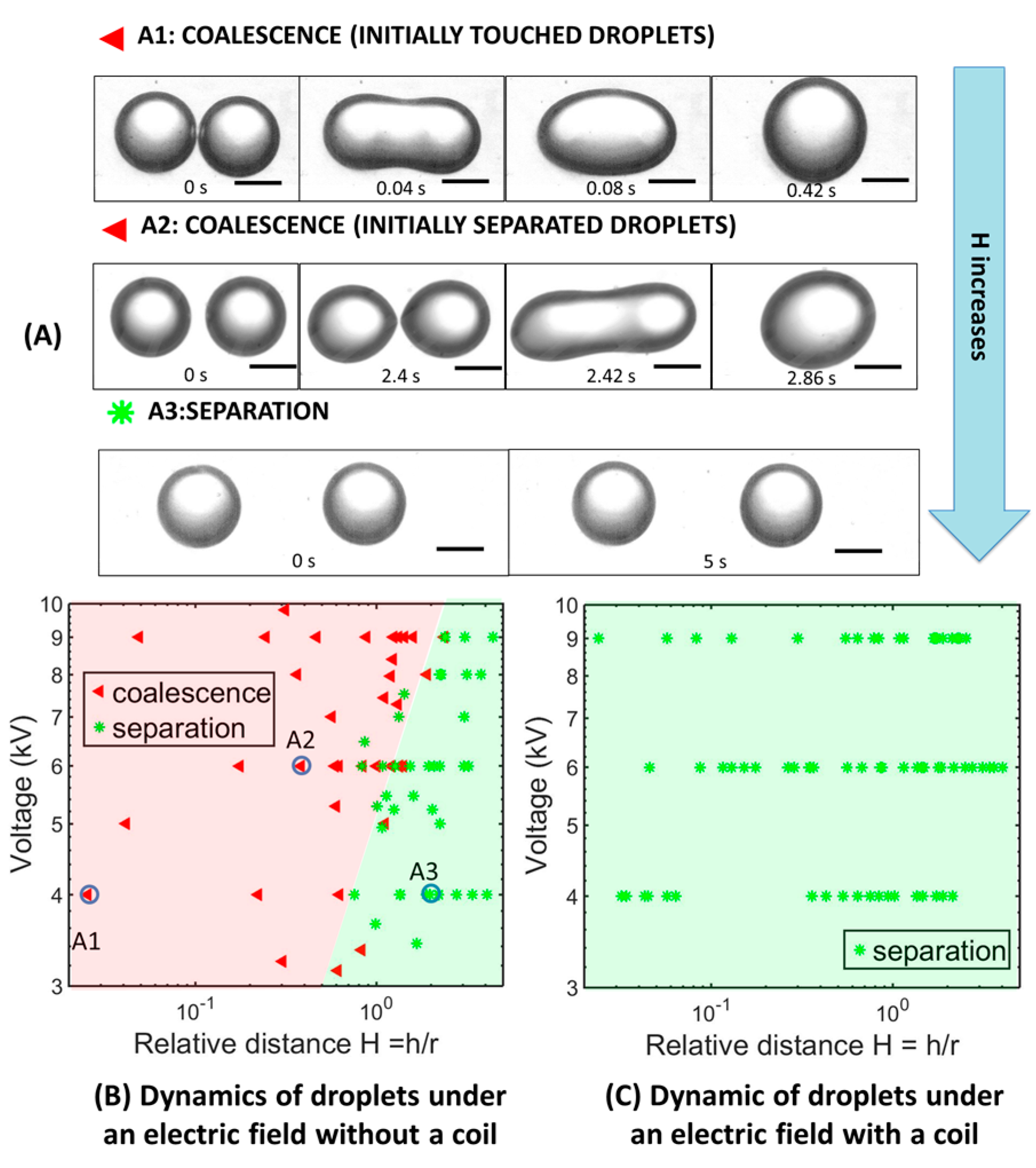
4.1. Dynamic Behaviors of Droplet Pairs under an Electric Field

Upon contact, two droplets will coalesce into a single one to minimize the total surface area [30,31]. In microfluidics, such coalescence can be prevented by adding surfactants. These surfactant molecules can absorb to the droplet interfaces and provide a repulsive pressure [11,32] to avoid the direct contact of the droplets [32]. Due to the presence of this repulsive pressure, emulsion droplets do not easily coalesce even when they are sheared by the flows in a microchannel or squeezed by the hydrostatic pressure when densely packed in a container. For instance, by adding 3 wt % EM90, a nonionic surfactant, into our continuous phase of paraffin, PEG droplets do not coalesce when they touch, as shown in Figure 3A1, t = 0 s.
In an electric field, two surfactant-stabilized droplets can be forced to coalesce. For two touching emulsion droplets, an electric field will induce accumulation of opposite charges on the opposing interfaces. The charged interfaces attract each other and provide an electric stress to drive the approach of liquid droplets against the repulsive pressure [33]. For instance, in an electric field with an intensity of 1.3 × 10⁵ V/m, two emulsion droplets stabilized using 3 wt % EM90 can be forced to coalesce, as shown in Figure 3A1.
Figure 3. (A) Dynamic behaviors of droplets in an electric field: (A1) Coalescence of two touching droplets; (A2) Coalescence of two droplets which are slightly separated; (A3) Separation of two droplets. Scale bars are 300 μm. At t = 0 s, a high voltage is applied with an intensity of: 4 kV (A1,A3); 6 kV (A2). Dynamic behaviors of droplets in the device (B) without a coil and (C) with a coil, under different applied voltages and relative distances, H.
Micromachines 06 01430 g003
Similar to the touching droplets, two separated droplets can also be forced to touch and coalesce in a sufficiently large electric field. The applied electric field can polarize the droplets with a charge density of [34]:
P polarized   ~   ε 0 ε c ( ε d 1 ) ε d + 2 ε c E
where εd and εc are the dielectric constants of the droplet and continuous phases respectively. In our experiment, the charged droplet phase has a much larger dielectric constant than the continuous phase, εd >> εc. Therefore, the electric stress on the droplets can be written as [7]:
σ E   ~   ε 0 ε c E 2
This electric stress will elongate a droplet and force it to adopt an elliptical shape. When the elongation of the droplet is small, the increase in the length, l, of the droplet along the direction of the electric field can be written as [34]:
l ~ r 2 ε 0 ε c E 2 γ
where r is the radius of the droplet. Indeed, when the distance between the two separated droplets is small, for example, 90 μm, as shown in Figure 3A2, an applied electric field with intensity of 2 × 10⁵ V/m, can elongate them and cause coalescence. However, when the distance between the separated droplets is sufficiently large, on the order of the droplets’ radius, the applied electric field can no longer force the droplets to touch by elongation, resulting in the separation of the droplets, as shown in Figure 3A3 [33].
Therefore, as we readily increase the distance between the two separated droplets (H), the behaviors of droplets in an electric field will change from coalescence to separation. Moreover, the applied electric field intensity that can trigger droplet coalescence increases with increasing separation distance. We summarize the droplet behaviors in terms of the relative distance and the applied voltage. For example, when the relative distance, H, is smaller than 0.5, droplets will coalesce upon an applied voltage of 3 kV; as H increases to 1, an applied voltage of 5 kV leads to coalescence; when H increases to 2, droplets remain in separation even when the applied voltage reaches 9 kV during the experiment.

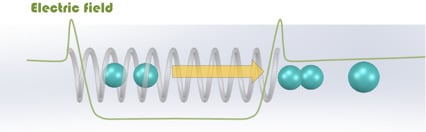
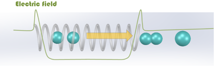
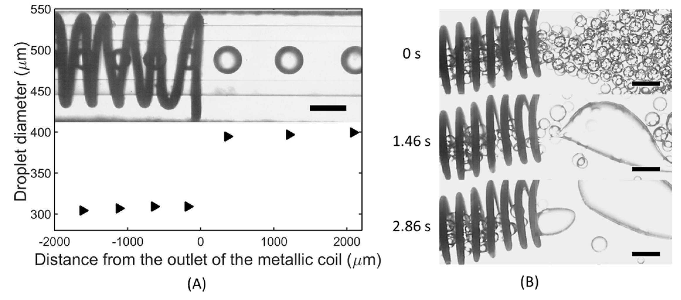
4.2. Preventing Electro-Coalescence Using a Metallic Coil

To prevent the electro-coalescence of the droplet pairs, we propose to shield the electric field by inserting a metallic coil into the micro-channel. Under an applied voltage, the electric field’s intensity inside the metallic coil should be much smaller than the one without the coil. Thus, the droplets inside the metallic coil can remain separated at an applied voltage that would trigger their coalescence without the coil. Indeed, with the applied voltage of 4 kV, two touching droplets coalesce in the microchannel without the metallic coil. In contrast, the droplets remain separated at the same applied voltage inside the metallic coil, as shown in Figure 3C. Even when the applied voltage is increased to 9 kV, these droplets still do not coalesce. Thus, the inserted metallic coils can prevent the touching emulsion droplets from coalescence.

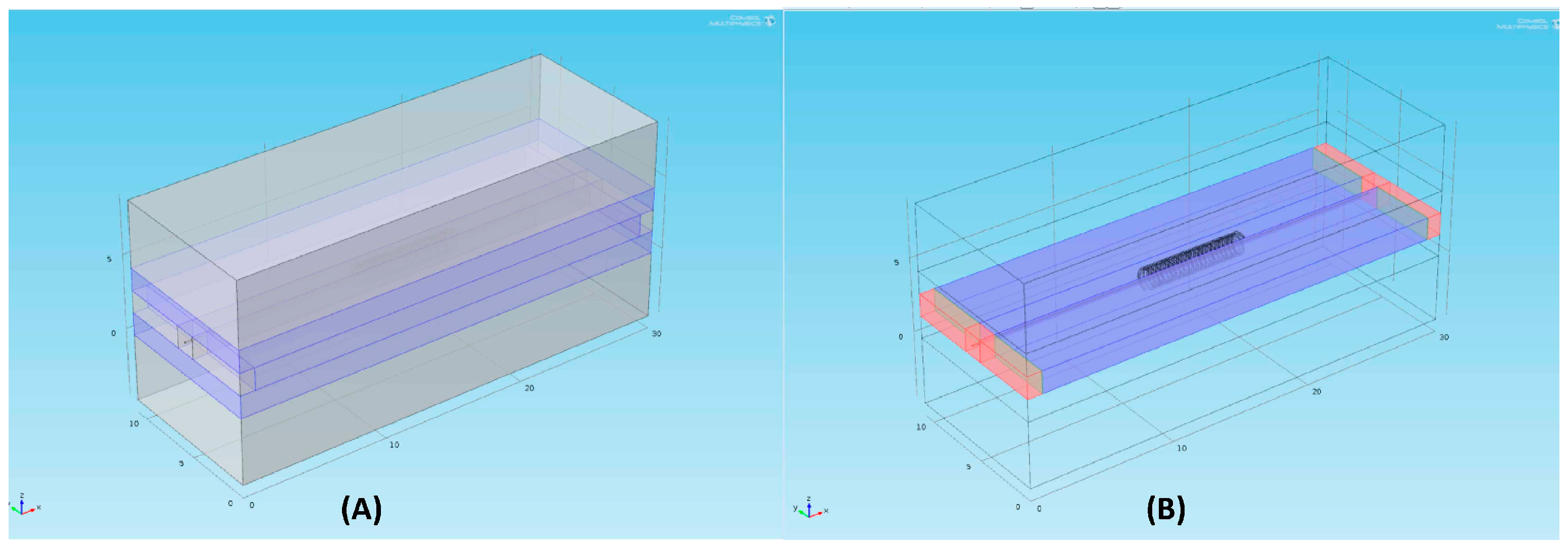
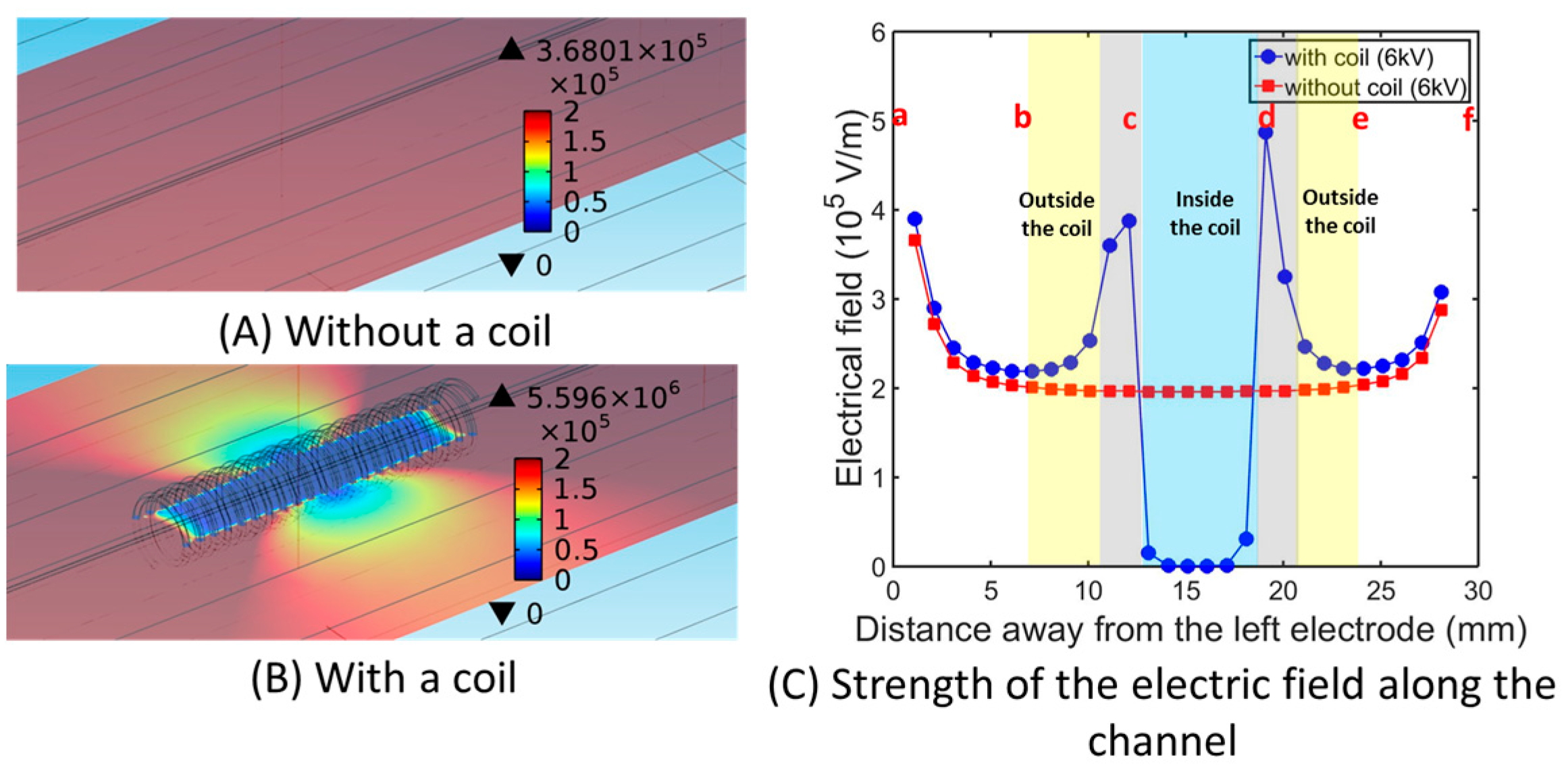
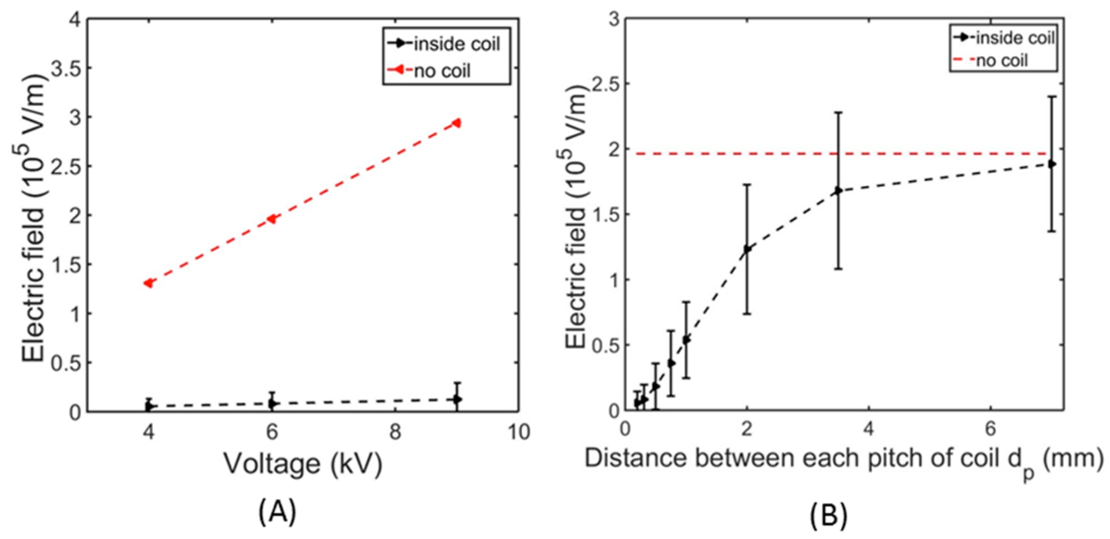
4.3. Numerical Simulation of the Electric Field Intensity Using COMSOL

To investigate and quantify the shielding efficiency of the inserted metallic coil, we used COMSOL to simulate the electric field in the modified devices with metallic coils under different applied voltages. For the device without a coil, the electric field strength in the channel was relatively uniform along the channel, as shown in Figure 4A. In addition, the value of the electric field from the numerical simulation was in good agreement with the one calculated using experimental parameters ( E =   U L ). For instance, when a voltage of 6 kV was applied, the simulated electric field in the channel without coil was around 1.96 × 10⁵ V/m, which is almost the same as the calculated electric field strength of 2 × 10⁵ V/m. In the presence of a metallic coil, the electric field’s strength can be dramatically reduced, as shown in Figure 4B. At an applied voltage of 6 kV, the electric field’s strength inside the coil was simulated to be: (8.3 ×10³ ± 1.1 × 10⁴) V/m, which is just 5% of the one in the device without a coil, as shown in Figure 4C. Even when the applied voltage is increased to 9KV, the electric field’s strength inside the coil is much smaller than the one without a coil, as shown in Figure 5A.
Figure 4. Simulation of the electric field in microfluidic devices. The simulated electric field strength in the device: (A) without a coil; (B) with a coil. The scarlet color indicates the electric field strength is above 2 × 10⁵ V/m. The navy blue indicates the electric field is close to 0 V/m; (C) Simulated electric field strength along the observation channel: blue dots (with a metallic coil); red squares (without a coil). The applied voltage is 6 kV. The yellow regions represent the space outside the coil; the gray regions represent the inlet and outlet of the coil; the blue region represents the space inside the coil. Points “a”, “b”, “c”, “d”, “e” and “f” represent the left electrode, the inlet of the droplet flow, the inlet of the coil, the outlet of the coil, the outlet of the droplet flow and the right electrode respectively.
Micromachines 06 01430 g004
While the 3D metallic coil can decrease the electric field inside it significantly, it is also important to know the dependence of shielding effectiveness on the density of the coil. Such coil density can be characterized by the pitch distance of the coil (dp). The denser the coil is, the smaller dp will be. For the same applied voltage, when dp decreases, the simulated average electric field strength decreases as well, indicating a better shielding effect. For instance, when we decrease the pitch distance from 7 to 1 mm, the average electric field inside the coil decreases from 1.88 × 10⁵ to 5.7 × 10⁴ V/m, as shown in Figure 5B. Therefore, metallic coils with small pitch distance are favored to achieve an optimized effect of shielding the applied electric field. While the electric field is dramatically reduced inside the coil, the electric field outside the coil will be maintained. Thus, there is a sharp transition in the electric field’s strength as the fluids enter and exit the section of the micro-channels enclosed by the metallic coil. For instance, at an applied voltage of 6 kV, the electric field’s strength outside the coil changes from almost zero to (2.3 ± 0.12) × 105 V/m after exiting the coil, as shown in Figure 4C. Experimentally, at an applied voltage of 7.9 kV, pairs of neighboring droplets only start to coalesce as they approach the edge of the metallic coils, leading to an increase in droplet diameter from 310 to 395 μm, as shown in Figure 6A (see the Supplementary Movie S1). For a concentrated emulsion, at an applied voltage of 3 kV, a corresponding transition from a dense population of stable droplets inside the coil to electro-coalesced droplets outside the coil is also observed, as shown in Figure 6B (see the Supplementary Movie S2). These observations suggest a sharp decline in shielding effect near the edge of the metallic coil, confirming the effectiveness of our approach for spatially tailoring the distribution of electric fields.
Figure 5. (A) The simulated electric field inside the coil compares with the one without coil; dp = 0.31 mm. (B) The simulated electric field inside coils with various pitch distances.
Micromachines 06 01430 g005
Figure 6. Dynamic behaviors of droplets in the device installed with a metallic coil when a voltage of (A) 7.9 kV is applied to a train of neighboring droplets; (B) 3 kV is applied to a dense population of emulsion droplets after 0 s. (A) A plot of the droplet diameter as a function of the distance from the outlet of the metallic coil. Inset: An optical microscope image of droplets as they exit the section of micro-channel surrounded by the coil. (B) A series of optical microscope images indicating the electro-coalescence of the droplets as they exit the metallic coil. Scale bars are 500 μm.
Micromachines 06 01430 g006

5. Conclusions

Electric fields can change the behaviors of droplets significantly. For instance, emulsion droplets tend to coalesce in the presence of an applied electric field. However, an uncontrolled electric field will induce unintended coalescence, which is undesired in many practical applications. We devised an approach to shield unwanted electric fields by including a 3D metallic coil around microfluidic channels. We showed that the inserted metallic coil can successfully shield an electric field and prevent touching droplets from coalescence. By numerically simulating the electric field within the modified microfluidic device, we demonstrated that the shielding effectiveness depends on the density of coil pitches. The shielding effectiveness increases with the increase of coil density. Our proposed approach of inserting a 3D metallic coil into microfluidic channels offers a simple, robust and effective approach to prevent undesired electro-coalescence by locally reducing the electric field. This approach can be easily adapted to tailor the electric field with custom-designed intensity in sophisticated and integrated microfluidic devices for applications involving electric fields.

Supplementary Materials

Supplementary materials can be accessed at: https://www.mdpi.com/2072-666X/6/10/1430/s1. Supplementary Movie S1: Protection of a metallic coil from electro-coalescence of a train of slightly separated droplets—a movie of dynamic behaviors of a train of slightly separated droplets in a glass channel (outer diameter is 1 mm) surrounded with a metallic coil when a voltage of 7.9 kV is applied. This movie is recorded at 10 frames per second and is played at 50 frames per second. Supplementary Movie S2: Protection of a metallic coil from electro-coalescence of a dense population of droplets—a movie of dynamic behaviors of a dense population of droplets in the device installed with a metallic coil when a voltage of 3 kV is applied. This movie is recorded at 100 frames per second and is played at 50 frames per second.

Acknowledgments

We thank Ping Zhao (Department of electronic engineering, Chinese University of Hong Kong) for assistance with the simulation using COMSOL. This research was supported by the General Program (21476189/B060201) and Young Scholar’s Program (NSFC51206138/E0605) from the National Natural Science Foundation of China, as well as the Early Career Scheme (HKU 707712P) and the General Research Fund (HKU 719813E and 17304514) from the Research Grants Council of Hong Kong.

Author Contributions

Jingmei Li and Ho Cheung Shum conceived and designed the experiments; Jingmei Li, Zhou Liu and Ho Cheung Shum wrote the paper; Jingmei Li, Haibo Huang performed the experiments; Jingmei Li conducted the simulation with the assistance from Ping Zhao.

Conflicts of Interest

The authors declare no conflict of interest.

References

  1. Abate, A.R.; Hung, T.; Mary, P.; Agresti, J.J.; Weitz, D.A. High-throughput injection with microfluidics using picoinjectors. Proc. Natl. Acad. Sci. USA 2010, 107, 19163–19166. [Google Scholar] [PubMed]
  2. Song, Y.; Chan, Y.K.; Ma, Q.; Liu, Z.; Shum, H.C. All-Aqueous Electrosprayed Emulsion for Templated Fabrication of Cytocompatible Microcapsules. ACS Appl. Mater. Interfaces 2015, 7, 13925–13933. [Google Scholar] [CrossRef] [PubMed]
  3. Niu, X.; Gielen, F.; deMello, A.J.; Edel, J.B. Electro-Coalescence of Digitally Controlled Droplets. Anal. Chem. 2009, 81, 7321–7325. [Google Scholar] [CrossRef] [PubMed]
  4. Kim, H.; Luo, D.; Link, D.; Weitz, D.A.; Marquez, M.; Cheng, Z. Controlled production of emulsion drops using an electric field in a flow-focusing microfluidic device. Appl. Phys. Lett. 2007, 91, 133106. [Google Scholar] [CrossRef]
  5. Gañán-Calvo, A.M.; Dávila, J.; Barrero, A. Current and droplet size in the electrospraying of liquids. Scaling laws. J. Aerosol Sci. 1997, 28, 249–275. [Google Scholar] [CrossRef]
  6. Doshi, J.; Reneker, D.H. Electrospinning Process and Applications of Electrospun Fibers. In Proceedings of the Conference Record of the 1993 IEEE Industry Applications Society Annual Meeting, Toronto, ON, Canada, 2–8 October 1993; pp. 1698–1703.
  7. Thiam, A.R.; Bremond, N.; Bibette, J. Breaking of an Emulsion under an ac Electric Field. Phys. Rev. Lett. 2009, 102, 188304. [Google Scholar] [CrossRef] [PubMed]
  8. Eow, J.S.; Ghadiri, M.; Sharif, A.O.; Williams, T.J. Electrostatic enhancement of coalescence of water droplets in oil: A review of the current understanding. Chem. Eng. J. 2001, 84, 173–192. [Google Scholar] [CrossRef]
  9. Taniguchi, T.; Torii, T.; Higuchi, T. Chemical reactions in microdroplets by electrostatic manipulation of droplets in liquid media. Lab Chip 2002, 2, 19–23. [Google Scholar] [CrossRef] [PubMed]
  10. O’Donovan, B.; Eastburn, D.J.; Abate, A.R. Electrode-free picoinjection of microfluidic drops. Lab Chip 2012, 12, 4029–4032. [Google Scholar] [CrossRef] [PubMed]
  11. Liu, Z.; Chan, S.T.; Faizi, H.A.; Roberts, R.C.; Shum, H.C. Droplet-based electro-coalescence for probing threshold disjoining pressure. Lab Chip 2015, 15, 2018–2024. [Google Scholar] [CrossRef] [PubMed] [Green Version]
  12. Ahn, K.; Kerbage, C.; Hunt, T.P.; Westervelt, R.; Link, D.R.; Weitz, D. Dielectrophoretic manipulation of drops for high-speed microfluidic sorting devices. Appl. Phys. Lett. 2006, 88, 24104–24104. [Google Scholar] [CrossRef]
  13. Guo, M.T.; Rotem, A.; Heyman, J.A.; Weitz, D.A. Droplet microfluidics for high-throughput biological assays. Lab Chip 2012, 12, 2146–2155. [Google Scholar] [CrossRef] [PubMed]
  14. Cho, S.K.; Moon, H.; Chang-Jin, K. Creating, transporting, cutting, and merging liquid droplets by electrowetting-based actuation for digital microfluidic circuits. J. Microelectromech. Syst. 2003, 12, 70–80. [Google Scholar]
  15. Pollack, M.; Shenderov, A.; Fair, R. Electrowetting-based actuation of droplets for integrated microfluidics. Lab Chip 2002, 2, 96–101. [Google Scholar] [CrossRef] [PubMed]
  16. Li, J.; Mittal, N.; Mak, S.Y.; Song, Y.; Shum, H.C. Perturbation-induced droplets for manipulating droplet structure and configuration in microfluidics. J. Micromech. Microeng. 2015, 25, 084009. [Google Scholar] [CrossRef]
  17. Eggers, J.; Villermaux, E. Physics of liquid jets. Rep. Prog. Phys. 2008, 71, 036601. [Google Scholar] [CrossRef]
  18. Deng, N.-N.; Wang, W.; Ju, X.-J.; Xie, R.; Weitz, D.A.; Chu, L.-Y. Wetting-induced formation of controllable monodisperse multiple emulsions in microfluidics. Lab Chip 2013, 13, 4047–4052. [Google Scholar] [CrossRef] [PubMed]
  19. Okushima, S.; Nisisako, T.; Torii, T.; Higuchi, T. Controlled Production of Monodisperse Double Emulsions by Two-Step Droplet Breakup in Microfluidic Devices. Langmuir 2004, 20, 9905–9908. [Google Scholar] [CrossRef] [PubMed]
  20. Loghavi, L.; Sastry, S.K.; Yousef, A.E. Effect of moderate electric field frequency and growth stage on the cell membrane permeability of Lactobacillus acidophilus. Biotechnol. Prog. 2009, 25, 85–94. [Google Scholar] [CrossRef] [PubMed]
  21. Hamilton, W.A.; Sale, A.J.H. Effects of high electric fields on microorganisms: II. Mechanism of action of the lethal effect. Biochim. Biophys. Acta BBA General Subj. 1967, 148, 789–800. [Google Scholar] [CrossRef]
  22. Cerri, G.; de Leo, R.; Primiani, V.M. Theoretical and experimental evaluation of the electromagnetic radiation from apertures in shielded enclosure. IEEE Trans. Electromagn. Compat. 1992, 34, 423–432. [Google Scholar] [CrossRef]
  23. O’Donovan, B.; Tran, T.; Sciambi, A.; Abate, A. Picoinjection of Microfluidic Drops without Metal Electrodes. J. Vis. Exp. 2014, 2014, e50913. [Google Scholar] [CrossRef] [PubMed]
  24. Thomas, P.; Ravindran, R.E.; Varma, K. Dielectric properties of Poly (methyl methacrylate)(PMMA)/CaCu3Ti4O12 composites. In Proceedings of the 2012 IEEE 10th International Conference on the Properties and Applications of Dielectric Materials (ICPADM), Bangalore, India, 24–28 July 2012; pp. 1–4.
  25. Relative Permittivity-Dielectric Constant. Available online: http://www.engineeringtoolbox.com/relative-permittivity-d_1660.html (accessed on 11 August 2015).
  26. Lourtioz, J.-M.; Benisty, H.; Berger, V.; Gerard, J.-M.; Maystre, D.; Tchelnokov, A. Photonic Crystals: Towards Nanoscale Photonic Devices; Springer: Berlin, Germany, 2006; pp. 121–122. [Google Scholar]
  27. Hussien, B. The DC and AC electrical properties of (PMMA-Al2O3) composites. Eur. J. Sci. Res. 2011, 52, 236–242. [Google Scholar]
  28. Tables of Physical & Chemical Constants (16th Edition 1995) 2.6.3 Electrical Insulating Materials. Available online: http://www.kayelaby.npl.co.uk/general_physics/2_6/2_6_3.html (accessed on 11 August 2015).
  29. Electrical Resistivity and Conductivity. Available online: https://en.wikipedia.org/wiki/Electrical_resistivity_and_conductivity (accessed on 11 August 2015).
  30. Mollet, H.; Grubenmann, A. Formulation Technology: Emulsions, Suspensions, Solid Forms; John Wiley & Sons: Hoboken, NJ, USA, 2008; p. 60. [Google Scholar]
  31. Baroud, C.N.; Gallaire, F.; Dangla, R. Dynamics of microfluidic droplets. Lab Chip 2010, 10, 2032–2045. [Google Scholar] [CrossRef] [PubMed]
  32. Stubenrauch, C.; von Klitzing, R. Disjoining pressure in thin liquid foam and emulsion films—New concepts and perspectives. J. Phys. Condens. Matter 2003, 15, R1197. [Google Scholar]
  33. Liu, Z.; Wyss, H.M.; Fernandez-Nieves, A.; Shum, H.C. Dynamics of oppositely charged emulsion droplets. Phys. Fluids 2015, 27, 082003. [Google Scholar]
  34. Allan, R.; Mason, S. Particle behaviour in shear and electric fields. I. Deformation and burst of fluid drops. Proc. R. Soc. Lond. A Math. Phys. Eng. Sci. 1962, 267, 45–61. [Google Scholar] [CrossRef]

