Article

A Rapid and Low-Cost Nonlithographic Method to Fabricate Biomedical Microdevices for Blood Flow Analysis

1
School of Technology and Management (ESTiG), Polytechnic Institute of Bragança (IPB), Campus de Santa Apolónia, 5300-253 Bragança, Portugal
2
Transport Phenomena Research Center, Department of Chemical Engineering, Engineering Faculty, University of Porto, Rua Dr. Roberto Frias, 4200-465 Porto, Portugal
3
Laboratory of Catalysis and Materials—Associate Laboratory LSRE/LCM, Engineering Faculty, University of Porto, Rua Dr. Roberto Frias, 4200-465 Porto, Portugal
4
Department of Mechanical Engineering, Minho University, Campus de Azurém, 4800-058 Guimarães, Portugal
*
Author to whom correspondence should be addressed.
Micromachines 2015, 6(1), 121-135; https://doi.org/10.3390/mi6010121
Submission received: 27 October 2014 / Accepted: 16 December 2014 / Published: 30 December 2014
(This article belongs to the Special Issue Micro/Nano Fabrication)

Abstract

:
Microfluidic devices are electrical/mechanical systems that offer the ability to work with minimal sample volumes, short reactions times, and have the possibility to perform massive parallel operations. An important application of microfluidics is blood rheology in microdevices, which has played a key role in recent developments of lab-on-chip devices for blood sampling and analysis. The most popular and traditional method to fabricate these types of devices is the polydimethylsiloxane (PDMS) soft lithography technique, which requires molds, usually produced by photolithography. Although the research results are extremely encouraging, the high costs and time involved in the production of molds by photolithography is currently slowing down the development cycle of these types of devices. Here we present a simple, rapid, and low-cost nonlithographic technique to create microfluidic systems for biomedical applications. The results demonstrate the ability of the proposed method to perform cell free layer (CFL) measurements and the formation of microbubbles in continuous blood flow.

1. Introduction

Microfluidic systems have become an increasingly popular interdisciplinary technology with applications in many fields, such as engineering, biology, and medicine [1,2,3,4]. Generally, these systems have characteristic dimensions of one to 1000 μm, and combine electrical and mechanical components at the micro-scale level. Microfluidic systems work with small sample volumes, shorter reaction times, and can perform massive amount of parallel operations. By integrating several steps into a single system, microfluidic devices allow performing rapid measurements in a single step and, consequently, they offer great potential to develop portable and point-of-care devices [3,5].
One of most popular and traditional methods to fabricate microfluidic devices is the soft lithography technique, with polydimethylsiloxane (PDMS) structures made from SU-8 molds [6,7,8]. The SU-8 molds are produced by photolithography. The main attraction of this technology is due, mainly, to its high-resolution capabilities, low material cost, gas permeability, and optical transparency [6]. However, the photolithographic production of molds usually requires a clean-room environment and specialized equipment that can be quite costly, and the process is time consuming. These drawbacks are currently slowing down development, especially in research institutions without specialized facilities to produce molds by photolithography. Access to rapid microfabrication methods is essential to improve development cycles and to test new chip designs and research ideas. Hence, it is crucial to develop simple, rapid, and low-cost nonlithographic techniques to fabricate microfluidic systems.
Nonlithographic techniques, also known as print-and-peel (PAP) [9], were first reported at the beginning of this century, using a xerographic process to fabricate molds for PDMS microfluidic microdevices [10]. Later on, Branham et al. [11] demonstrated the application of a laser jet printer to fabricate PDMS microdevices. A few years later, Bao et al. [12] used this PAP technique to perform capillary electrophoresis. Chen et al. [13] proposed the use of pre-stressed thermoplastic sheets, which shrink when heated, as a base material for low cost microfluidics. Bonyár et al. [14] demonstrated the ability of 3D rapid prototyping technology to produce functional microfluidic devices and molds for PDMS microchannels. Other low cost non-lithographic technologies were reviewed by Waldbaur et al. [15], including laser direct machining [16] and Inkjet 3D printing [17]. A PAP method, known as xurography, has shown to be an effective, novel, and rapid prototyping technique to fabricate microfluidic channels [18]. Xurography uniquely uses a cutting plotter machine and adhesive vinyl films to generate the master molds, or to directly fabricate the microchannels, and, consequently, does not involve any photolithographic processes. Recently, Sundberg et al. [19] demonstrated the application of this PAP approach to create microfluidic channels to perform DNA melting analysis. However, no work has been performed yet to test biomimetic separations.
An important application of microfluidics is blood rheology in microchannels, which has played a key role in recent developments of lab-on-chip devices for blood sampling and analysis [20,21,22,23]. Blood is a non-Newtonian fluid, containing an extremely rich amount of information about the physiological and pathological state of the human body. Hence, there is an evident interest to develop microfluidic devices for the diagnosis of major diseases, such as cancer, diabetes mellitus, and cardiovascular disorders. The traditional method for creating the microfluidic devices is soft lithography, using molds obtained by photolithography. By using this fabrication technique Shevkoplyas et al. [24] developed a microdevice to isolate white blood cells (WBCs) from a blood sample by using the margination effect, whereas Hou et al. [25] have very recently proposed a biomimetic separation device to separate normal and malaria infected red blood cells (RBCs). Other researchers, such as Faivre et al. [26], Sollier et al. [27], and Pinho et al. [22], have demonstrated that the cell free layer (CFL) could be enhanced by using a microchannel containing a constriction followed by a sudden expansion to separate plasma from the whole in vitro blood.
Although the results are extremely encouraging, the high costs and time involved in the traditional photolithography process are currently slowing down the development and diffusion of biomimetic separation biochips among a large research and industrial community. Hence, there is a demand for low-cost and short fabrication time methods to produce microfluidic systems. Here, we introduce a low-cost nonlithographic technique, known as bioxurography, due to its fast fabrication time, independence from clean room facilities and low material and equipment cost, as an ideal solution to manufacture affordable microfluidic devices to work on the scales required to perform blood cell analysis in continuous flow.

2. Materials and Methods

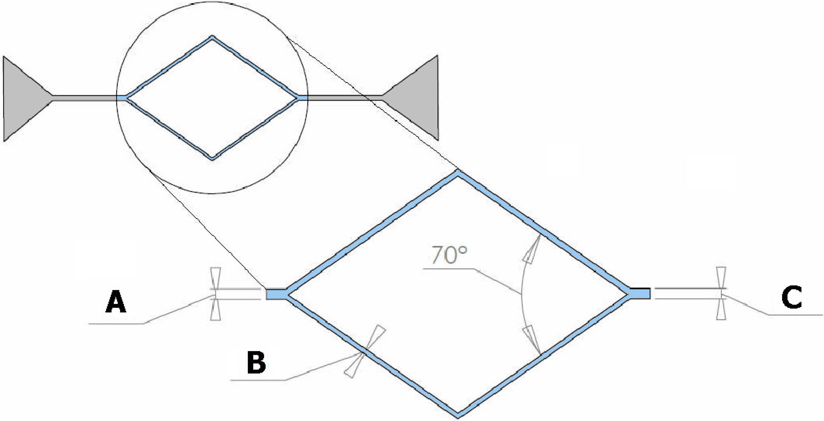
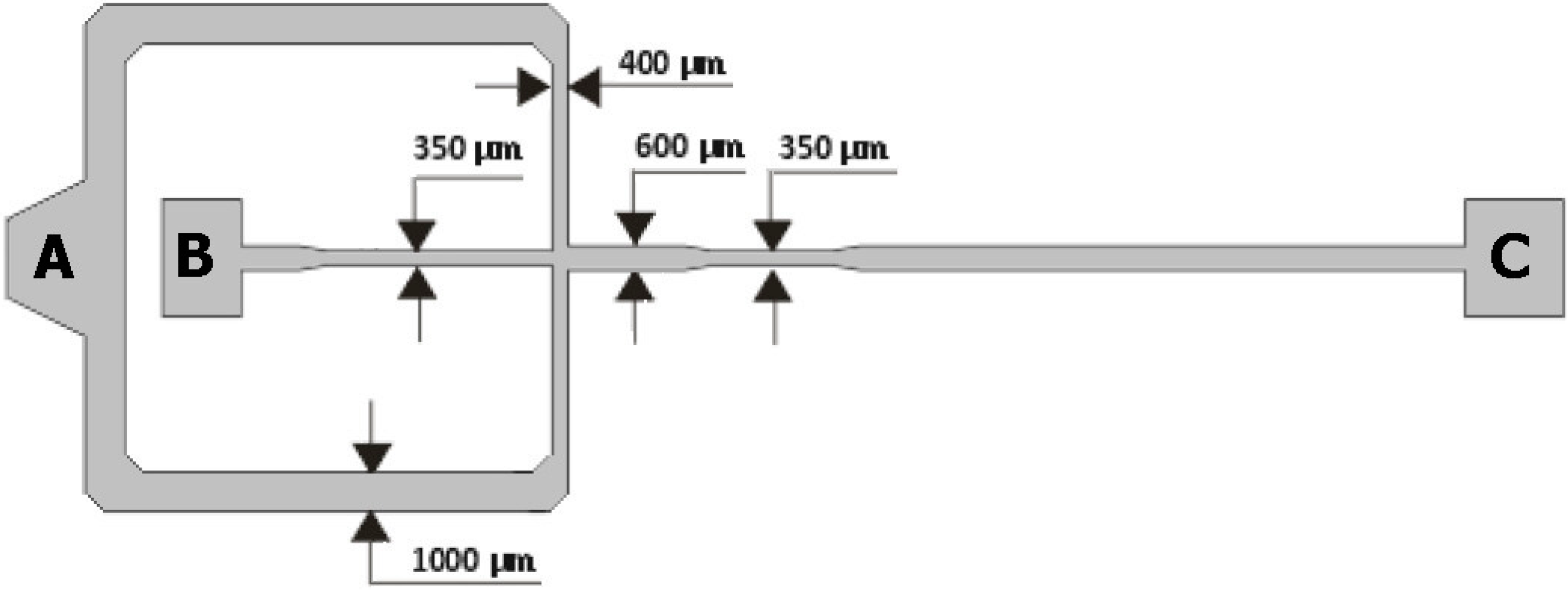
2.1. Geometries of the Microchannels

The molds for the microfluidic devices tested in this study were fabricated using a xurography technique and consist of two main geometries: a microchannel with a diverging and converging bifurcation and a flow-focusing microfluidic device. Figure 1 and Figure 2 show the geometries and main dimensions of the microfluidic devices tested in this study. For the first case (see Figure 1), the geometries were selected taking into account a previous study performed on the blood flow behavior through microchannels with bifurcations and confluences fabricated by a soft lithography technique [7]. Here, due to the limitation of the xurography technique, the minimum dimension of the microchannel width was around 150 µm. Hence, the parent microchannel had a minimum width of 300 µm and maximum width of 1000 µm whereas the two branches of the bifurcation and confluence correspond to 50% of parent channel width. Chips with three different channel dimensions were studied; with parent channel dimensions of 300, 500 and 1000 µm.
The geometry used for the second biomedical application was based on a flow-focusing device often used to generate droplets [28]. For this particular example, we tested this device to generate bubbles of air flowing through in vitro blood.
Figure 1. Schematic diagram of the microchannel geometry with a diverging and converging bifurcation where the width of channels A and C are 300, 500, or 1000 μm, and the widths of respective ramifications B are 150, 250, or 500 μm.
Micromachines 06 00121 g001
Figure 2. Schematic diagram of the microfluidic flow-focusing device geometry used to generate bubbles where continuous phase (in vitro blood) and dispersed phase (air) are introduced in A and B, respectively, and C is the outlet of mixture of both phases.
Micromachines 06 00121 g002

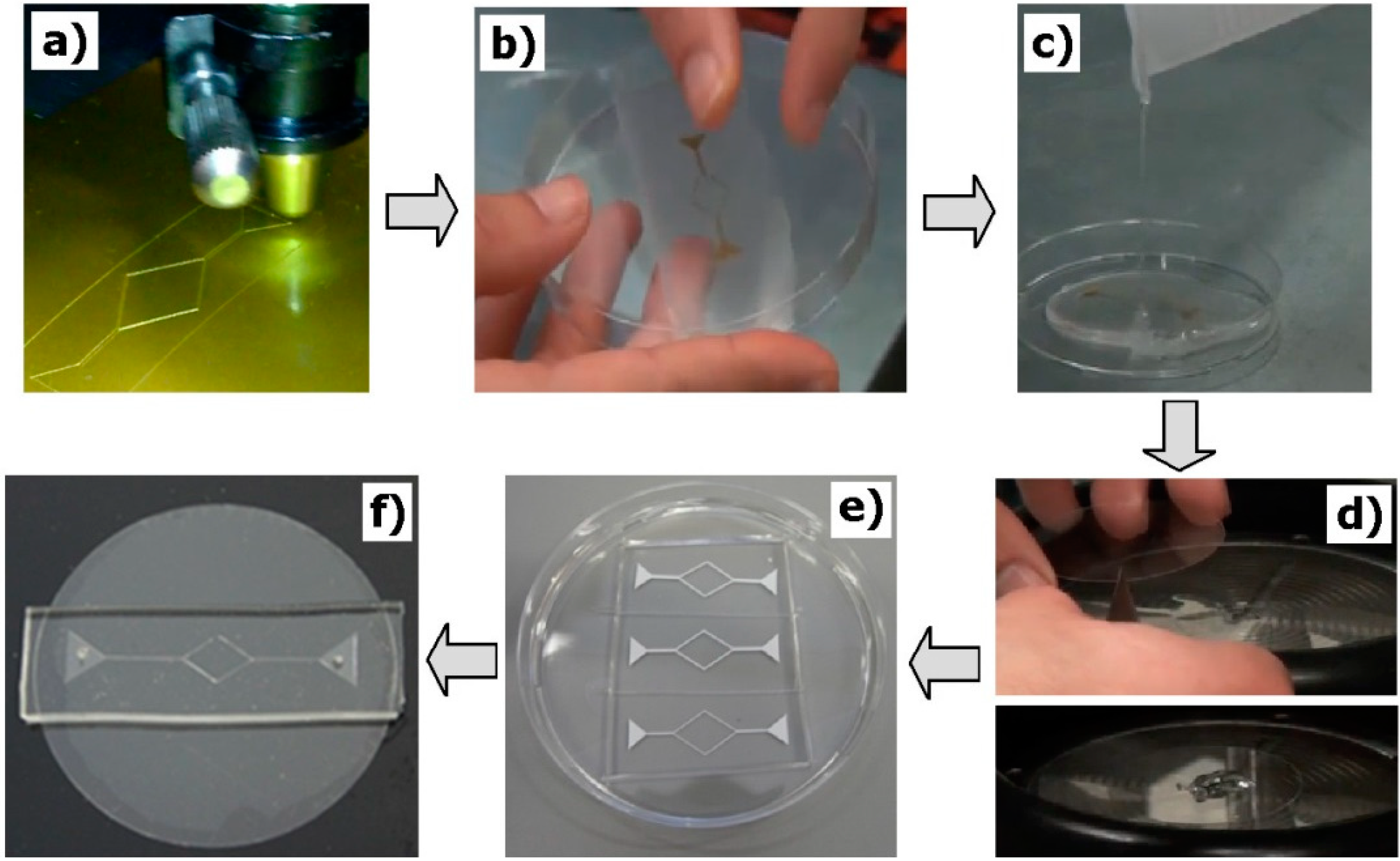
2.2. Fabrication of the Microfluidic Devices

The tested microchannels were fabricated by a xurography technique, which can be performed at low cost in a straightforward manner. Specifically, the fabrication process, which is outlined in Figure 3, was as follows:
(a)
The microchannel geometries were drawn using a CAD software, and then the molds were cut by using a cutting plotter Jaguar II (GCC Innovation, Capelle aan den Ijssel, The Netherlands).
(b)
Adhesive paper was used to transfer and place the mold master inside the petri dish.
(c)
The PDMS prepolymer was prepared by mixing a commercial prepolymer and a curing agent (10:1 ratio) and poured onto master mold in the petri dish and cured in an oven at 80 °C for 20 min.
(d)
The PDMS (20:1 ratio) was spin coated over a glass slide and cured in an oven at 80 °C for 20 min.
(e)
By using a blade, the microchannels were cut off and the inlet/outlet holes of the fluid were done by using a fluid-dispensing tip.
(f)
Finally, the channels were sealed by the PDMS covered glass slides. To have a strong adhesion of the materials, the device was placed in the oven at 80 °C for 24 h.
Figure 3. Main steps of the fabrication procedure: (a) Cutting the CAD geometries in the vinyl paper by means of a cutting plotter; (b) transfer the mold to the petri dish using an adhesive; (c) pouring the polymer PDMS over the mold to obtain the microchannel; (d) spin coating a slide glass with PDMS; (e) remove the cured PDMS microchannel from the vinyl mold; (f) three-dimensional PDMS microchannel with the input/output ports sealed with the spin-coated glass slide.
Micromachines 06 00121 g003

2.3. Working Fluids

The working fluid used in the first tested device (see Figure 1) was ovine red blood cells suspended with dextran 40 (Dx40). In this study we have used a hematocrit (Hct) of 5% and 15%. For the case of the flow-focusing device, the working fluids were air and Dx40 containing about 10% Hct of ovine RBCs. Briefly, blood was collected from a healthy ovine; heparin was added in order to prevent coagulation. The RBCs were separated from bulk blood by centrifugation (2000 rpm for 15 min at 4 °C) and then the plasma and buffy coat were removed by aspiration. The RBCs were then washed twice with a physiological saline solution and diluted with Dx40 to make up the required RBC concentration. All blood samples were stored hermetically at 4 °C until the experiments were performed at a room temperature of approximately 20 °C.

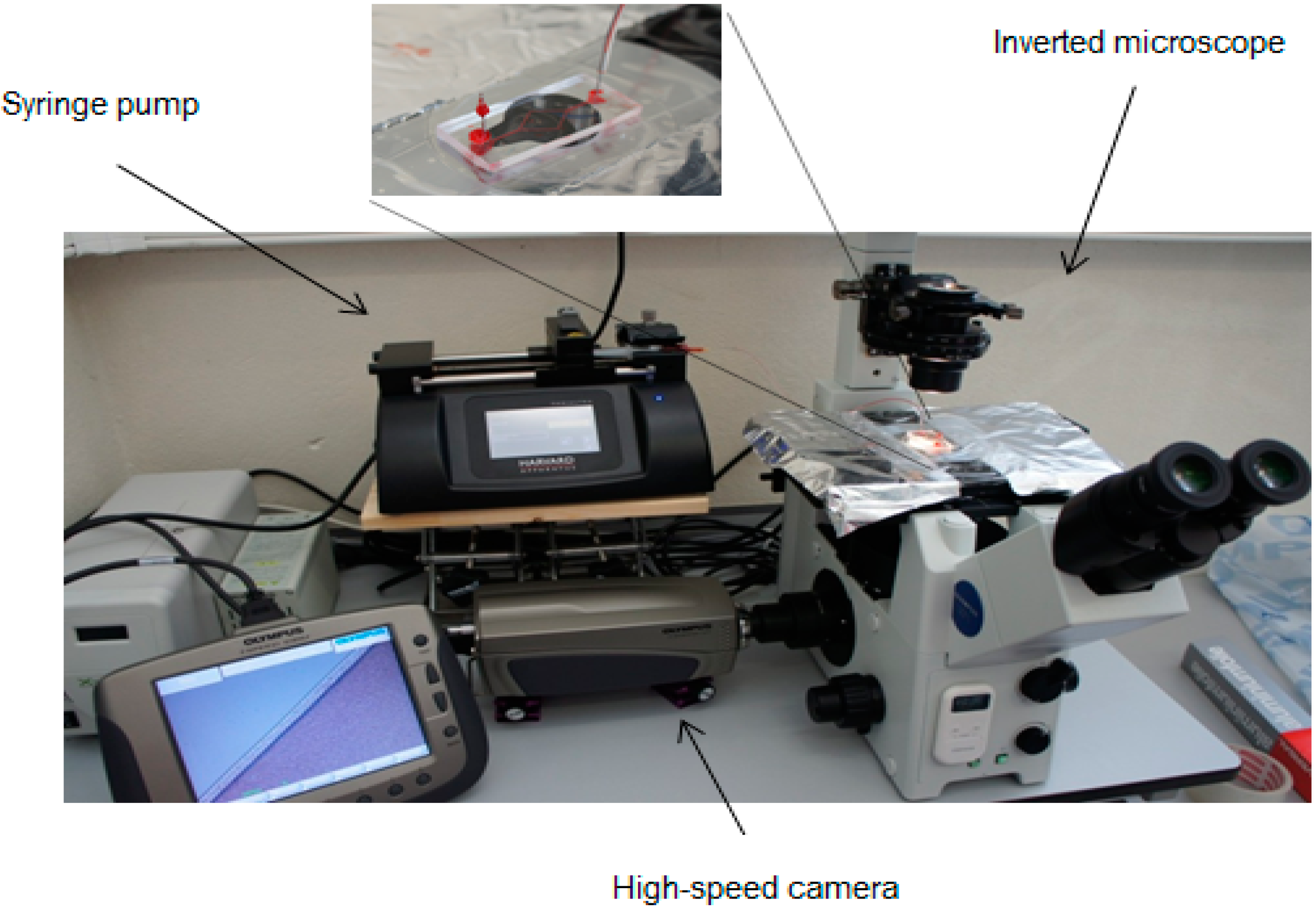
2.4. Experimental Set-Up

The high-speed video microscopy system used in both studies is shown in Figure 4. The main part of this system consists of an inverted microscope (IX71, Olympus, Tokyo, Japan) and a high-speed camera (i-SPEED LT, Olympus). All the microfluidic devices were placed on the stage of the inverted microscope. A syringe pump (Harvard Apparatus PHD ULTRA, Holliston, MA, USA) was used to produce a constant flow rate. Note that, for the flow-focusing device, an additional pressure pump (Elveflow AF1 PG1113, Paris, France) was used to inject air at a constant pressure in the microchannel. Figure 4 shows the main experimental equipment used to control and visualize the fluids flowing through the microchannels.
Figure 4. Main experimental equipment used to control and visualize the flow in microchannels produced by xurography.
Micromachines 06 00121 g004

2.5. Image Analysis

A manual tracking plugin (MTrackJ) of the image analysis software ImageJ [29] was used to track individual RBC flowing around the boundary of the RBCs core (Point 2 in Figure 5). By using the MTrackJ plugin, the centroid of the selected RBC was automatically computed [30]. Besides, the nearest wall position was measured (Point 1 in Figure 5) so that the distance between the tracked RBCs and the wall can be calculated, which consequently draws the CFL thickness (Figure 5).
To visualize the CFL formation in the microchannels, the captured videos were converted to a sequence of static images (stack) and then, by using “Z project” function in ImageJ, it was possible to obtain a single image having a sum of all static images. In this image, the darker region indicates RBC core and brighter region indicates CFL.
Figure 5. Tracking an individual red blood cell (RBC) flowing around the boundary of the RBCs core.
Micromachines 06 00121 g005

3. Results and Discussion

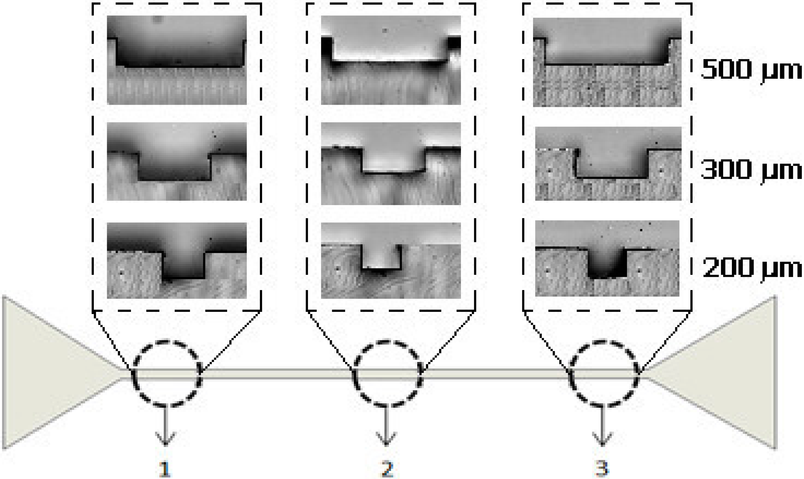
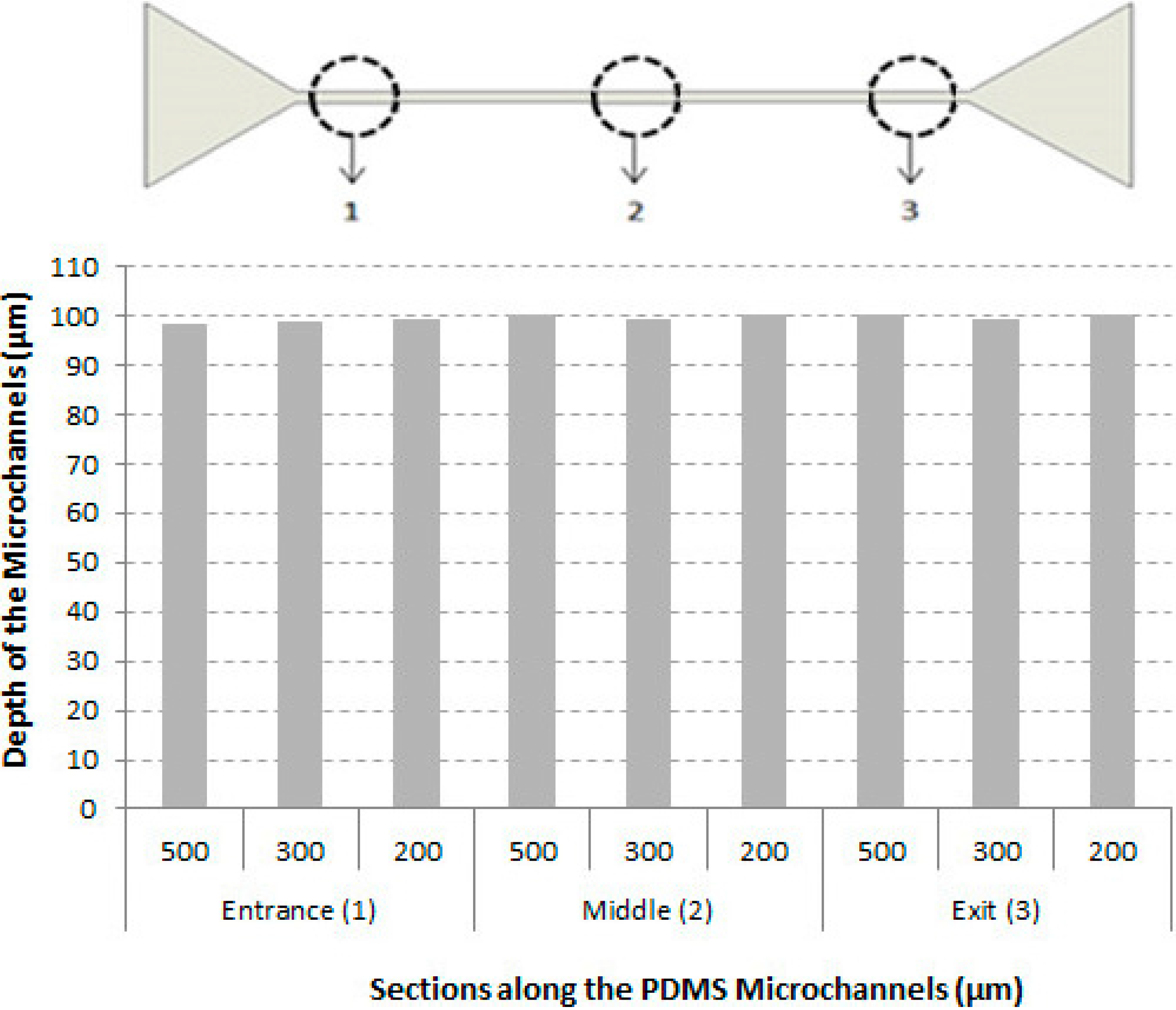
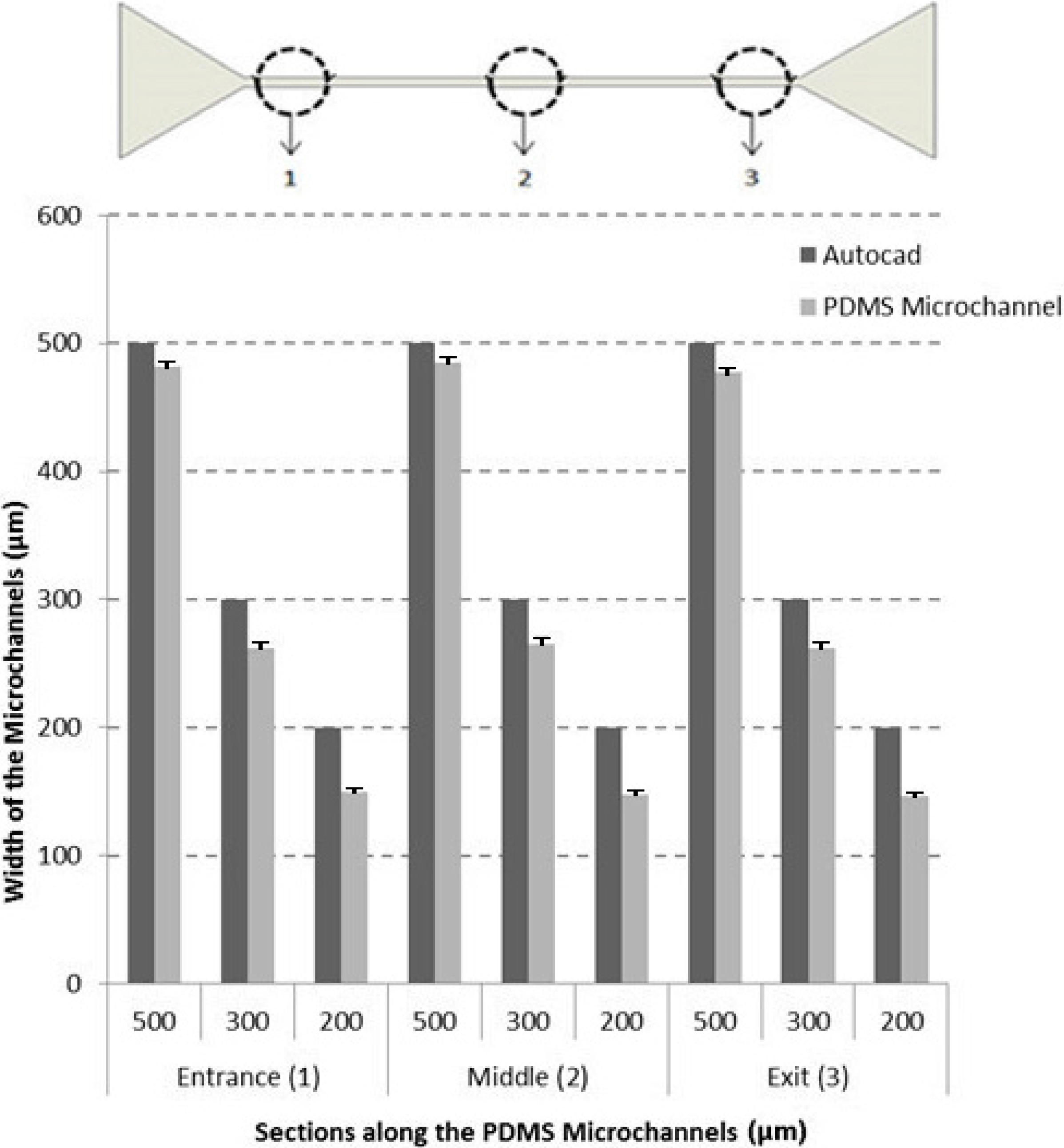
3.1. Characteristics of the Microchannels

To evaluate the geometrical quality of the mold masters and correspondent microchannels, several microscopic images were obtained along a device with a simple geometry. Light micrographs of the PDMS microchannels, fabricated using the proposed technique are shown in Figure 6. It also shows a schematic representation of the sections where the microscopic images were taken.
Figure 6. Schematic representation of the microchannel geometry and location of the sections where the microscopic images were collected to evaluate the geometrical quality. From left to right we have: (1) entrance, (2) middle, and (3) exit.
Micromachines 06 00121 g006
The geometrical qualities of the PDMS microchannels were evaluated using ImageJ and the ranges of values measured for all sections along the microchannels are shown in Figure 7 and Figure 8. Figure 7 shows the comparison between the AutoCAD projected values and actual width measurements of the PDMS microchannels and consequently from the vinyl master molds. Figure 8 shows the depth measurements of the PDMS microchannels at three different sections, i.e., entrance (1), middle (2), and exit (3).
Detailed microscopic visualizations have shown that the difference between the microchannel and the actual dimensions of the PDMS microchannel tends to increase by decreasing the size of the geometry. For instance, in Figure 7, it is possible to observe that the highest difference occurs for the smallest microchannels. This is mainly related to the limitation of our cutting plotter to cut precisely geometries with dimensions smaller than 500 µm, i.e., microchannels with 300 and 200 µm widths. In contrast, no significant difference was observed for the depth of microchannels (99.4 ± 1.4 μm).
Figure 7. Comparison between the values projected from AutoCAD and width measurements of the PDMS microchannels at three different sections: entrance (1), middle (2), and exit (3). The measurements are expressed as the mean ± standard deviation according to a t-test analysis at 95% confidence interval.
Micromachines 06 00121 g007
Figure 8. Depth measurements in three different sections: entrance (1), middle (2), and exit (3).
Micromachines 06 00121 g008

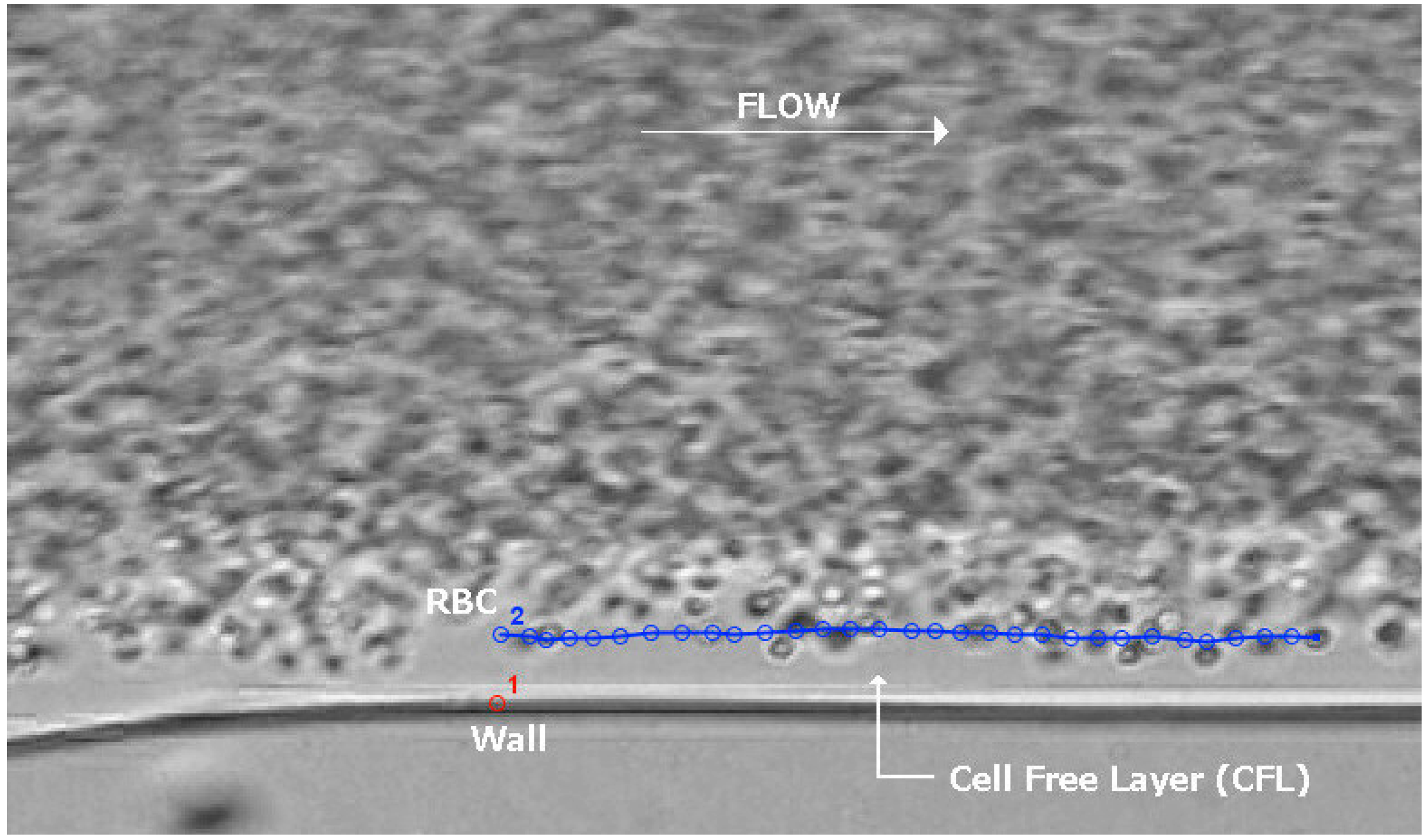
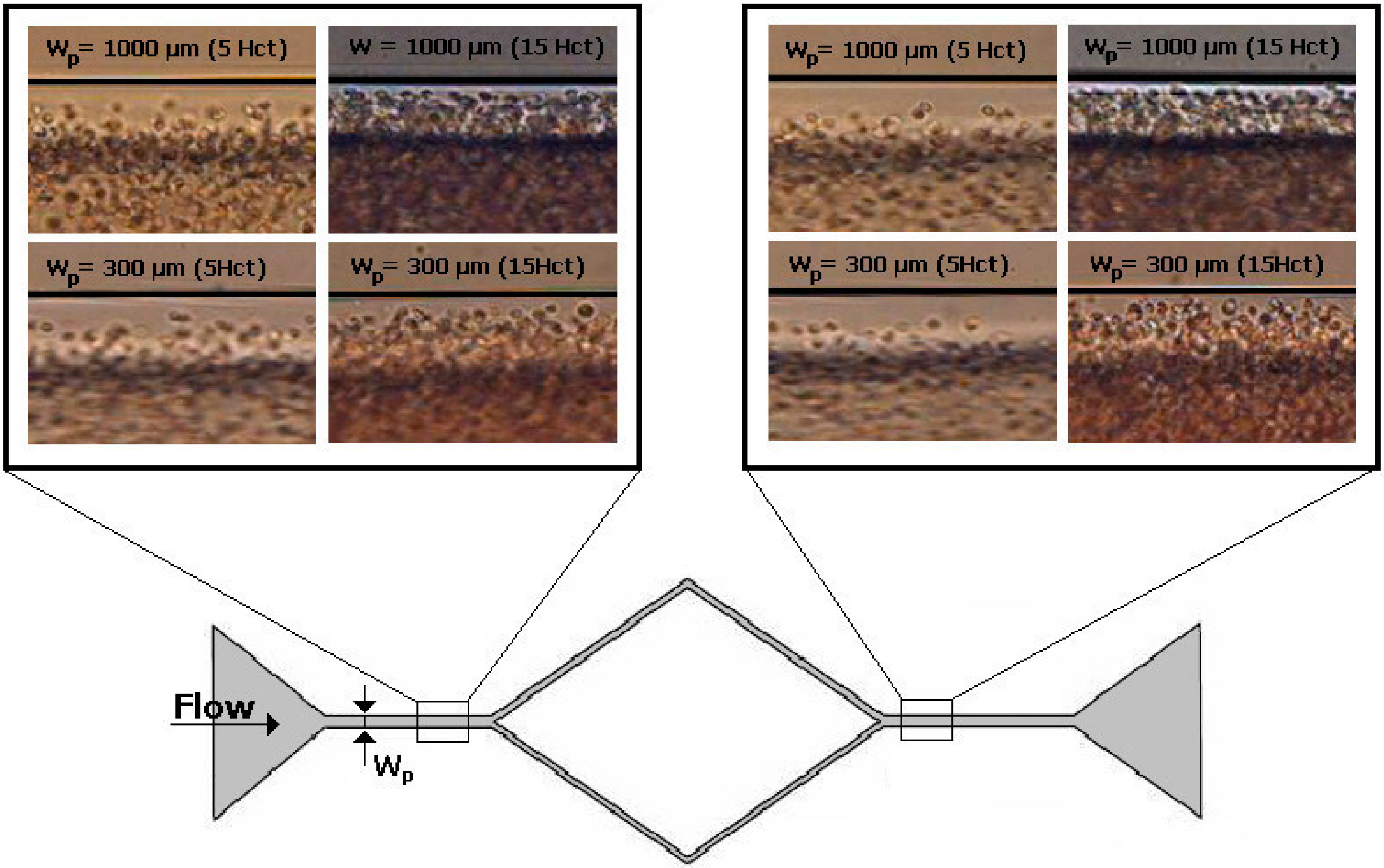
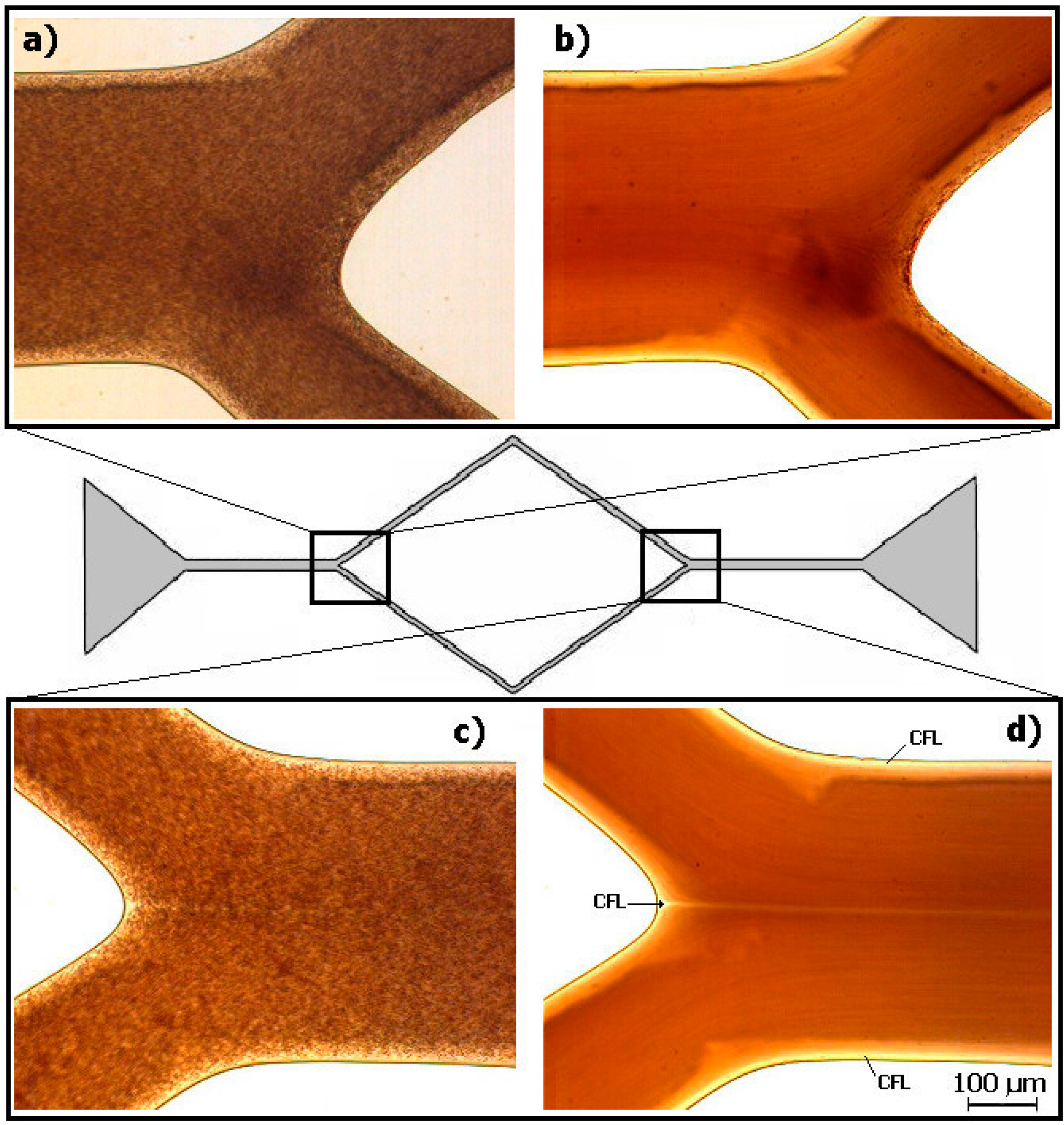
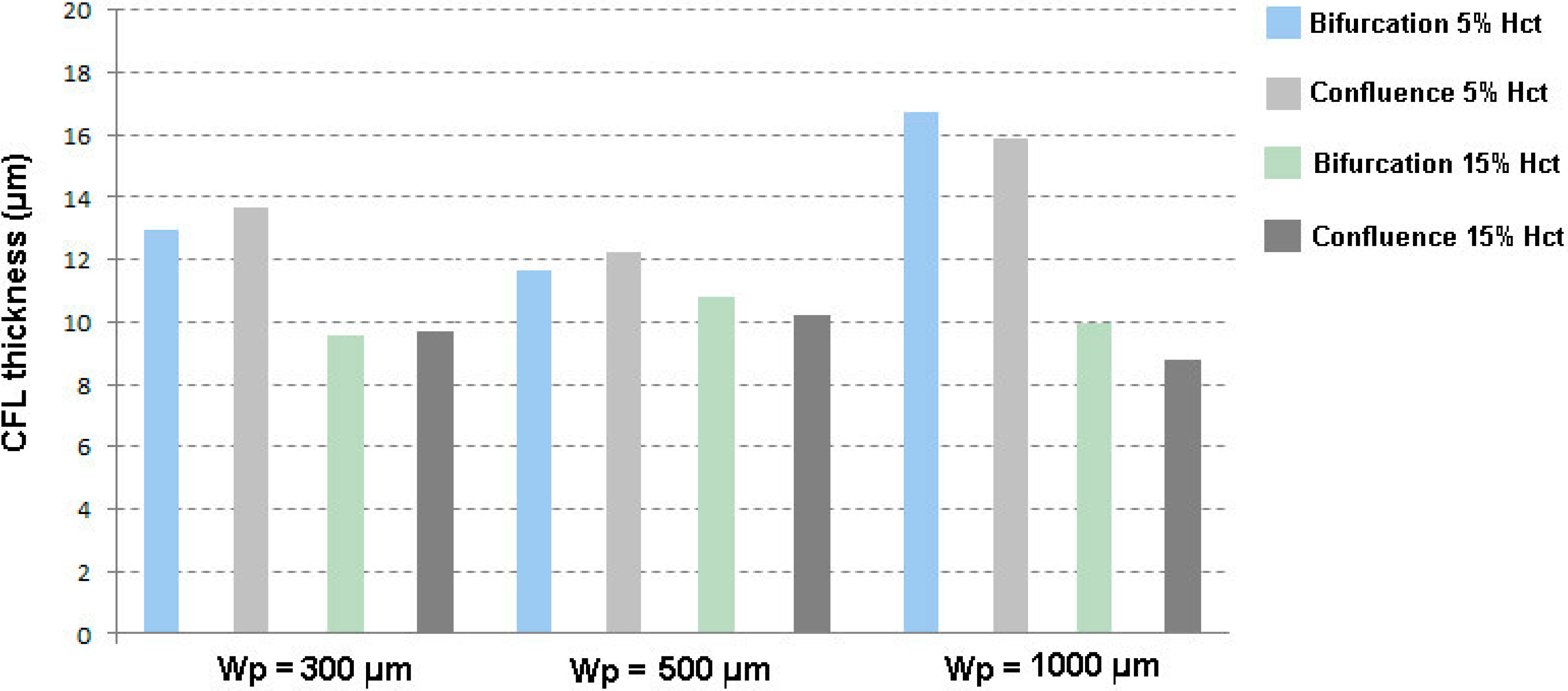
3.2. Cell-Free Layer (CFL) Measurements and Visualization

In addition to a tendency of the RBCs to undergo axial migration induced by the cells’ tank treading motion, high wall shear stress forces the RBCs to move towards the center of the vessel. As a result, there is a formation of CFL with extremely low concentration of cells along the walls of the microchannels. In straight microchannels, the CFL can be defined as the distance between the microchannel wall and the boundary region of the RBCs core. Although the formation of the CFL in vivo [31,32,33] has been of great interest over many years, little information is available about this phenomenon mainly due to the limitation of the measurement techniques. Recently, several researchers [7,22,34] have attempted to replicate this phenomenon in vitro using biomedical microdevices in order to better understand it and explore its potential as a new diagnostic tool. Here, we show the effect of the Hct and geometry of a microcahnnel fabricated by xurography on CFL formation (Figure 9).
Figure 10 shows the results for CFL thickness for a constant flow rate of 10 μL/min, of 5% Hct and 15% Hct in a microchannel with a diverging and converging bifurcation for a width of the parent channel (Wp) of 300, 500, and 1000 μm. Note that all the CFL measurements were executed where the CFL had a steady formation, i.e., at the regions where the CFL is parallel to the wall. The results show that the CFL thickness is not strongly affected by the bifurcation, whereas it decreases with increasing Hct. This latter result corroborates with the past results performed in both in vivo [31,33] and in vitro [34] experiments.
Figure 11 shows the visualization of in vitro blood with 15% Hct flowing in a microchannel with a bifurcation followed by a confluence. All original images were converted by means of the “Z project” function (ImageJ) to a single image having a sum of all static images. The qualitative results show clearly the formation of a CFL not only around the walls but also in the region immediately after the confluence.
Figure 9. Visualization of in vitro blood with 5% Hct and 15% Hct flowing in a microchannel geometry with a diverging and converging bifurcation for a width of the parent channel (Wp) of 300 and 1000 μm. The flow rate was 10 μL/min.
Micromachines 06 00121 g009
Figure 10. CFL thickness measured in blood flows of 5% Hct and 15% Hct in a microchannel with a diverging and converging bifurcation for a width of the parent channel (Wp) of 300, 500, and 1000 μm. The flow rate was 10 μL/min.
Micromachines 06 00121 g010
Figure 11. Visualization of in vitro blood with 15% Hct flowing in a microchannel geometry with (a) diverging bifurcation (original image); (b) diverging bifurcation (the sum of all images); (c) converging bifurcation or confluence (original image), and (d) converging bifurcation or confluence (the sum of all images). The flow rate was 10 μL/min.
Micromachines 06 00121 g011
These results corroborate the works of Ishikawa et al. [35] and Leble et al. [7] that found a formation of a CFL in the region of the confluence apex. This phenomenon was observed in a microchannel three times smaller than the one used in the current study as they used a photolithographic technique to fabricate the molds for the microchannels. The current work has shown evidence that at width dimensions up to 500 μm there still is a formation of a CFL around the apex of the confluence. Hence, by using xurography it is possible to create an artificial CFL under appropriate hemodynamic and geometrical conditions, and as a result, to develop low cost microfluidic systems for biomedical applications, such as blood cell separation and analysis.

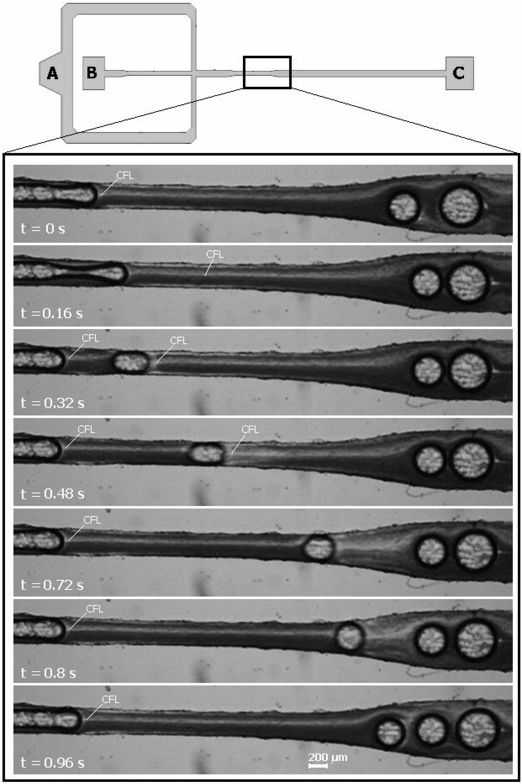
3.3. Bubbles Generation and Visualization

An air embolism is a pathological condition caused by bubbles trapped in a blood vessel [36,37]. During surgeries and other medical procedures, small amounts of air may get into the blood stream accidentally. Air bubbles may also be formed in the blood stream due to cavitation in prosthetic heart valves or during decompression after scuba diving activities [37]. When an air bubble flows through a blood vessel, it may block small arteries and stop blood supply to a certain area of the body. Although it could be fatal if a large amount of bubbles flows through blood arteries, there is not enough information about the amount of air bubbles, which might cause death. It is known that the rate of reabsorption of microbubbles may be accelerated by the injection in the blood stream of surfactants [38]. Hence, it is important to improve our understanding on the flow of bubbles in microchannels with dimensions similar to in vivo blood vessels. There is also a demand for biochips for the development of new strategies and new surfactant based drugs to treat air embolisms. The xurographic technique was, therefore, used to developed microfluidic systems capable of generating air bubbles moving through the microchannel (Figure 12).
Figure 12. Visualization of bubbles generation and in vitro blood flow containing bubbles through a flow-focusing device fabricated by xurography.
Micromachines 06 00121 g012
Figure 12 shows bubbles generation and in vitro blood flow containing bubbles in a flow-focusing device fabricated by xurography. The liquid phase (in vitro blood) enters at inlet A with a flow rate of 3 µL/min, whereas the gas phase (air) enters at inlet B with a pressure of 25 mbar. The gas and liquid streams flow along the main channel and two side channels, respectively, meeting at the cross-junction. Two-phase flow occurs in the main channel and exits at the outlet C. The size of the cross-section of the main channel is 600 µm wide and 100 µm high, but at the section near the junction point the width is 350 µm (Figure 12). The bubbles’ generation is as follows: the dispersed phase (air) is squeezed by two counter-streaming blood flows of the carrier phase, forcing the gas to breakup and to generate bubbles. Under these operating conditions, the bubbles were formed within the 350 µm wide microchannel, as shown in Figure 12. Two kinds of bubbles can be observed: slug bubbles, also known as Taylor bubbles, and spherical bubbles. First, bubbles with a slug shape are formed and keep their shape until they reach the 600 µm smooth expansion, where they acquired a circular shape. These slug bubbles flow through the microchannel, separated from each other by liquid slugs and from the wall by a thin liquid film. As expected, due to a lower cross section area of the 350 µm microchannel, the velocity of slug bubbles is higher than the spherical bubbles located in the expansion region of the microchannel. It is worth mentioning the formation of large bubbles in the expansion region of the microchannel. These bubbles are formed mainly due to the collision between them, which leads to coalescence. Another point of interest is the formation of a cell free layer among bubbles at the center of the microchannel. This phenomenon is presented and discussed in more detail elsewhere [39].
The qualitative results demonstrate that the proposed nonlithographic technique can generate air bubbles in a flow-focusing device and consequently enables the study of air embolism at a microscale level. In the near future, by using this technique, we plan to study in detail the flow behavior of air bubbles flowing in blood suspensions through geometries similar to in vivo microvessels.

4. Conclusions

Xurography was used to produce molds for the fabrication of microchannels by PDMS soft lithography. The accuracy of the method was evaluated by comparing the dimensions of the PDMS channels obtained with the nominal dimension of the AutoCAD design. The microchannels produced were applied to the study of two problems related to the blood flow in microchannels, the formation a CFL in bifurcations and confluences and the flow of microbubbles mimicking air embolisms.
Detailed analysis of the geometries has shown that the quality of the microchannel tends to decrease as its size decreases. This is mainly related to the limitation of our cutting plotter to cut precise geometries with dimensions smaller than 500 µm.
The molds and correspondent PDMS microchannels had good enough quality to study blood flow phenomena at the microscale level. It was possible to perform experiments to measure the CFL thickness with results consistent with the ones reported elsewhere in the literature. It was also possible to generate air bubbles by a flow-focusing device suitable for research of air embolisms.

Acknowledgments

The authors acknowledge the financial support provided by PTDC/SAU-BEB/105650/2008, PTDC/SAU-ENB/116929/2010, EXPL/EMS-SIS/2215/2013 and scholarship SFRH/BD/89077/2012 and SFRH/BD/97658/2013 from FCT (Science and Technology Foundation), COMPETE, QREN and European Union (FEDER).

Author Contributions

Elmano Pinto developed the fabrication process and performed the main experimental work. All authors have analyzed the data. Elmano Pinto has written the main manuscript and all authors reviewed the manuscript.

Conflicts of Interest

The authors declare no conflict of interest.

References

  1. Garcia, V.; Dias, R.; Lima, R. In vitro blood flow behaviour in microchannels with simple and complex geometries. In Applied Biological Engineering—Principles and Practice; Naik, G.R., Ed.; InTech: Rijeka, Croatia, 2012; pp. 393–416. [Google Scholar]
  2. Lima, R.; Nakamura, M.; Omori, T.; Ishikawa, T.; Wada, S.; Yamaguchi, T. Advances in Computational Vision and Medical Image Processing; Springer: Dordrecht, The Netherlands, 2009; pp. 203–220. [Google Scholar]
  3. Nguyen, N.T.; Wereley, S.T. Fundamentals and Applications of Microfluidics, 2nd ed.; Artech House: Boston, MA, USA, 2006. [Google Scholar]
  4. Stone, H.A.; Kim, S. Microfluidics: Basic issues, applications, and challenges. AIChE J. 2001, 47, 1250–1254. [Google Scholar] [CrossRef]
  5. Beebe, D.J.; Mensing, G.A.; Walker, G.M. Physics and applications of microfluidics in biology. Ann. Rev. Biomed. Eng. 2002, 4, 261–286. [Google Scholar] [CrossRef]
  6. Duffy, D.C.; McDonald, J.C.; Schueller, O.J.A.; Whitesides, G.M. Rapid prototyping of microfluidic systems in poly(dimethylsiloxane). Anal. Chem. 1998, 70, 4974–4984. [Google Scholar] [CrossRef] [PubMed]
  7. Leble, V.; Lima, R.; Dias, R.; Fernandes, C.; Ishikawa, T.; Imai, Y.; Yamaguchi, T. Asymmetry of red blood cell motions in a microchannel with a diverging and converging bifurcation. Biomicrofluidics 2011, 5. [Google Scholar] [CrossRef]
  8. Lima, R.; Wada, S.; Tanaka, S.; Takeda, M.; Ishikawa, T.; Tsubota, K.; Imai, Y.; Yamaguchi, T. In vitro blood flow in a rectangular pdms microchannel: Experimental observations using a confocal micro-piv system. Biomed. Microdevices 2008, 10, 153–167. [Google Scholar] [CrossRef] [PubMed]
  9. Thomas, M.S.; Millare, B.; Clift, J.M.; Bao, D.; Hong, C.; Vullev, V.I. Print-and-peel fabrication for microfluidics: What's in it for biomedical applications? Ann. Biomed. Eng. 2010, 38, 21–32. [Google Scholar] [CrossRef] [PubMed]
  10. Tan, A.; Rodgers, K.; Murrihy, J.; O’Mathuna, C.; Glennon, J.D. Rapid fabrication of microfluidic devices in poly(dimethylsiloxane) by photocopying. Lab Chip 2001, 1, 7–9. [Google Scholar] [CrossRef] [PubMed]
  11. Branham, M.L.; Tran-Son-Tay, R.; Schoonover, C.; Davis, P.S.; Allen, S.D.; Shyy, W. Rapid prototyping of micropatterned substrates using conventional laser printers. J. Mater. Res. 2002, 17, 1559–1562. [Google Scholar] [CrossRef]
  12. Bao, N.; Zhang, Q.; Xu, J.J.; Chen, H.Y. Fabrication of poly(dimethylsiloxane) microfluidic system based on masters directly printed with an office laser printer. J. Chromatogr. A 2005, 1089, 270–275. [Google Scholar] [CrossRef] [PubMed]
  13. Chen, C.-S.; Breslauer, D.N.; Luna, J.I.; Grimes, A.; Chin, W.C.; Lee, L.P.; Khine, M. Shrinky-dink microfluidics: 3D polystyrene chips. Lab Chip 2008, 8, 622–624. [Google Scholar] [CrossRef] [PubMed]
  14. Bonyár, A.; Sántha, H.; Ring, B.; Varga, M.; Gábor Kovács, J.; Harsányi, G. 3D rapid prototyping technology (rpt) as a powerful tool in microfluidic development. Procedia Eng. 2010, 5, 291–294. [Google Scholar] [CrossRef]
  15. Waldbaur, A.; Rapp, H.; Länge, K.; Rapp, B.E. Let there be chip—Towards rapid prototyping of microfluidic devices: One-step manufacturing processes. Anal. Methods 2011, 3, 2681–2716. [Google Scholar] [CrossRef]
  16. Klank, H.; Kutter, J.P.; Geschke, O. Co 2-laser micromachining and back-end processing for rapid production of pmma-based microfluidic systems. Lab Chip 2002, 2, 242–246. [Google Scholar] [CrossRef] [PubMed]
  17. Kaigala, G.V.; Ho, S.; Penterman, R.; Backhouse, C.J. Rapid prototyping of microfluidic devices with a wax printer. Lab Chip 2007, 7, 384–387. [Google Scholar] [CrossRef] [PubMed]
  18. Bartholomeusz, D.A.; Boutte, R.W.; Andrade, J.D. Xurography: Rapid prototyping of microstructures using a cutting plotter. J. Microelectromech. Syst. 2005, 14, 1364–1374. [Google Scholar] [CrossRef]
  19. Sundberg, S.O.; Wittwer, C.T.; Greer, J.; Pryor, R.J.; Elenitoba-Johnson, O.; Gale, B.K. Solution-phase DNA mutation scanning and snp genotyping by nanoliter melting analysis. Biomed. Microdevices 2007, 9, 159–166. [Google Scholar] [CrossRef] [PubMed]
  20. Abkarian, M.; Faivre, M.; Horton, R.; Smistrup, K.; Best-Popescu, C.A.; Stone, H.A. Cellular-scale hydrodynamics. Biomed. Mater. 2008, 3. [Google Scholar] [CrossRef]
  21. Gossett, D.R.; Weaver, W.M.; Mach, A.J.; Hur, S.C.; Tse, H.T.; Lee, W.; Amini, H.; Di Carlo, D. Label-free cell separation and sorting in microfluidic systems. Anal. Bioanal. Chem. 2010, 397, 3249–3267. [Google Scholar] [CrossRef] [PubMed]
  22. Pinho, D.; Yaginuma, T.; Lima, R. A microfluidic device for partial cell separation and deformability assessment. Biochip J. 2013, 7, 367–374. [Google Scholar] [CrossRef]
  23. Yaginuma, T.; Oliveira, M.S.; Lima, R.; Ishikawa, T.; Yamaguchi, T. Human red blood cell behavior under homogeneous extensional flow in a hyperbolic-shaped microchannel. Biomicrofluidics 2013, 7. [Google Scholar] [CrossRef]
  24. Shevkoplyas, S.S.; Yoshida, T.; Munn, L.L.; Bitensky, M.W. Biomimetic autoseparation of leukocytes from whole blood in a microfluidic device. Anal. Chem. 2005, 77, 933–937. [Google Scholar] [CrossRef] [PubMed]
  25. Hou, H.W.; Bhagat, A.A.; Chong, A.G.; Mao, P.; Tan, K.S.; Han, J.; Lim, C.T. Deformability based cell margination—A simple microfluidic design for malaria-infected erythrocyte separation. Lab Chip 2010, 10, 2605–2613. [Google Scholar] [CrossRef] [PubMed]
  26. Faivre, M.; Abkarian, M.; Bickraj, K.; Stone, H.A. Geometrical focusing of cells in a microfluidic device: An approach to separate blood plasma. Biorheology 2006, 43, 147–159. [Google Scholar] [PubMed]
  27. Sollier, E.; Cubizolles, M.; Fouillet, Y.; Achard, J.L. Fast and continuous plasma extraction from whole human blood based on expanding cell-free layer devices. Biomed. Microdevices 2010, 12, 485–497. [Google Scholar] [CrossRef] [PubMed]
  28. Baroud, C.N.; Gallaire, F.; Dangla, R. Dynamics of microfluidic droplets. Lab Chip 2010, 10, 2032–2045. [Google Scholar] [CrossRef] [PubMed]
  29. Abramoff, M.D.; Magalhaes, P.J.; Ram, S.J. Image processing with ImageJ. Biophoton. Int. 2004, 11, 36–42. [Google Scholar]
  30. Meijering, E.; Smal, I.; Danuser, G. Tracking in molecular bioimaging. IEEE Signal Proc. Mag. 2006, 23, 46–53. [Google Scholar] [CrossRef]
  31. Kim, S.; Ong, P.K.; Yalcin, O.; Intaglietta, M.; Johnson, P.C. The cell-free layer in microvascular blood flow. Biorheology 2009, 46, 181–189. [Google Scholar] [PubMed]
  32. Maeda, N.; Suzuki, Y.; Tanaka, J.; Tateishi, N. Erythrocyte flow and elasticity of microvessels evaluated by marginal cell-free layer and flow resistance. Am. J. Physiol. 1996, 271, 2454–2461. [Google Scholar]
  33. Tateishi, N.; Suzuki, Y.; Soutani, M.; Maeda, N. Flow dynamics of erythrocytes in microvessels of isolated rabbit mesentery: Cell-free layer and flow resistance. J. Biomech. 1994, 27, 1119–1125. [Google Scholar] [CrossRef] [PubMed]
  34. Lima, R.; Oliveira, M.S.; Ishikawa, T.; Kaji, H.; Tanaka, S.; Nishizawa, M.; Yamaguchi, T. Axisymmetric polydimethysiloxane microchannels for in vitro hemodynamic studies. Biofabrication 2009, 1. [Google Scholar] [CrossRef]
  35. Ishikawa, T.; Fujiwara, H.; Matsuki, N.; Yoshimoto, T.; Imai, Y.; Ueno, H.; Yamaguchi, T. Asymmetry of blood flow and cancer cell adhesion in a microchannel with symmetric bifurcation and confluence. Biomed. Microdevices 2011, 13, 159–167. [Google Scholar] [CrossRef] [PubMed]
  36. Barak, M.; Katz, Y. Microbubbles: Pathophysiology and clinical implications. Chest. J. 2005, 128, 2918–2932. [Google Scholar] [CrossRef]
  37. Papadopoulou, V.; Tang, M.X.; Balestra, C.; Eckersley, R.J.; Karapantsios, T.D. Circulatory bubble dynamics: From physical to biological aspects. Adv. Colloid Interface Sci. 2014, 206, 239–249. [Google Scholar] [CrossRef] [PubMed]
  38. Branger, A.B.; Eckmann, D.M. Accelerated arteriolar gas embolism reabsorption by an exogenous surfactant. Anesthesiology 2002, 96, 971–979. [Google Scholar] [CrossRef] [PubMed]
  39. Sousa, L. Estudo de Embolias Gasosas em Microcanais. Master’s Thesis, Instituto Politécnico de Bragança, Bragança, Portugal, 2013. [Google Scholar]

