Electromagnetic Micromotors—Design, Fabrication and Applications

Institute of Microtechnology, Technische Universität Braunschweig, 38124 Braunschweig, Germany
Micromachines 2014, 5(4), 929-942; https://doi.org/10.3390/mi5040929
Submission received: 24 September 2014
/
Accepted: 20 October 2014
/
Published: 24 October 2014
(This article belongs to the Special Issue Microactuators)
Abstract
:Microactuators have become essential elements of microelectromechanical systems, for example, for positioning purposes and for fluid-handling tasks in microfluidic systems. UV depth lithography and other new micromachining technologies, which have been developed since the 1990s, have initiated extensive investigations of electromagnetic microactuators, which are characterized by high forces, large deflections, low driving voltages resulting from low input impedances and robustness under harsh environments. This paper reviews the comprehensive research on the design, fabrication and application of electromagnetic micromotors performed in our laboratory over the past years.
1. Introduction
In conventional macro-scale machines linear and rotary motion, which is a characteristic feature of all machines, is most often generated by using electromagnetic actuation principles. On the micro-scale, since the 1980s initial investigations centered on electrostatic micromotors due to the fact that all processes for the fabrication of such devices were available from microelectronics technology [1,2]. At about the same time, on the basis of scale reduction considerations, a number of papers made the case for electrostatic rather than electromagnetic microactuation [3,4]. However, subsequently performed thorough examinations of the potential of magnetic interactions in microactuation have demonstrated a variety of advantages of magnetic micromotors [5,6,7]. Taking into account, for example, that current densities can be greatly increased on the micro-scale, proves that electromagnetic micromotors are able to produce large forces, which are at least comparable to those of electrostatic ones. Further performance advantages are low driving voltages resulting from low input impedances and robustness under harsh environments. In addition, it has been shown, that the use of integrated permanent magnets can generate additional potential for efficient magnetic microactuators.
First, however, substantial technological challenges hampered a rapid development of electromagnetic micromotors. Key components of such devices are three-dimensional microcoils and complex hard and soft magnetic microstructures, which correspond to wound coils and magnets in bulk actuators. In order to achieve high forces, both the electric conductors of the microcoils and the magnetic flux guiding structures have to exhibit large cross sections in order to allow for sufficiently high current and magnetic flux, respectively. Difficulties also arise due to the required thickness of the insulating layers. This means that three-dimensional micromachining technologies and, in the case of micromotors comprising permanent magnets, also efficient technologies for the integration of thick layers of hard magnetic material have to be used.
Initial attempts for realizing electromagnetic micromotors were based on hybrid technologies. Guckel et al. used the LIGA (Lithographie, Galvanoformung, Abformung) process [8] to fabricate high aspect ratio Ni microstructures constituting the stator and the rotor of a variable reluctance magnetic micromotor. The motor was operated by externally generated magnetic fields [9]. In a later version hybrid wire bonding techniques were used to create coils [10]. Wagner et al. [11] placed rare earth permanent magnet rotors onto integrated planar coils.
The first magnetically driven micromotor with fully integrated stator and coils, also based on the variable reluctance principle, was presented by Ahn et al. [12]. The motor used an electroplated 40 μm thick NiFe rotor and a 120 μm thick stator with a meander-type integrated inductive component which generates the magnetic flux. The electroplating molds were made of polyimide, which was patterned by plasma etching. The planar meander coils were manufactured by electroplating of Cu utilizing an 8 μm thick positive photoresist mold.
New UV sensitive photoresists allow exposure of thick layers of resist, i.e., layers of several 10 μm up to several 100 μm. With the advent of these resists a new technology for fabricating high aspect ratio microstructures has emerged, the so-called UV depth lithography or UV-LIGA method. This technique has been used to develop a variety of magnetic microactuators, such as, for example, scanning mirrors [13] and relays [14]. UV depth lithography also promises to provide an excellent technological basis for the development of linear and rotatory magnetic micromotors.
Since the late 1990s, these opportunities have been systematically investigated in our laboratory. In the following the technologies developed and their implementation in respect of different types of magnetic micromotors will be reviewed. Finally some applications will be discussed.
2. Electromagnetic Actuation Principles
The force density of the magnetic field is typically described by the Korteweg-Helmholtz force density derived from the quasistatic Poynting’s theorem. In the case of incompressible magnetizable media, i.e., μ ≠ f (ρ), the force per unit volume ![Micromachines 05 00929 i001]() is given as [15]:
is given as [15]:
![Micromachines 05 00929 i002]() where μ is the magnetic permeability, ρ the mass density,
where μ is the magnetic permeability, ρ the mass density, ![Micromachines 05 00929 i003]() the volume current density,
the volume current density, ![Micromachines 05 00929 i004]() the magnetic flux density, and
the magnetic flux density, and ![Micromachines 05 00929 i005]() the magnetic field intensity. The first term corresponds to the Lorentz force
the magnetic field intensity. The first term corresponds to the Lorentz force ![Micromachines 05 00929 i006]() , where
, where ![Micromachines 05 00929 i007]() is the electrical current. The second term describes the force due to a spatial change of magnetic permeability, the so-called reluctance force. In case of compressible media, there is a third term describing magnetostrictive forces [15].
is the electrical current. The second term describes the force due to a spatial change of magnetic permeability, the so-called reluctance force. In case of compressible media, there is a third term describing magnetostrictive forces [15].
 is given as [15]:

 the volume current density,
  the magnetic flux density, and
  the magnetic field intensity. The first term corresponds to the Lorentz force
  , where
  is the electrical current. The second term describes the force due to a spatial change of magnetic permeability, the so-called reluctance force. In case of compressible media, there is a third term describing magnetostrictive forces [15].
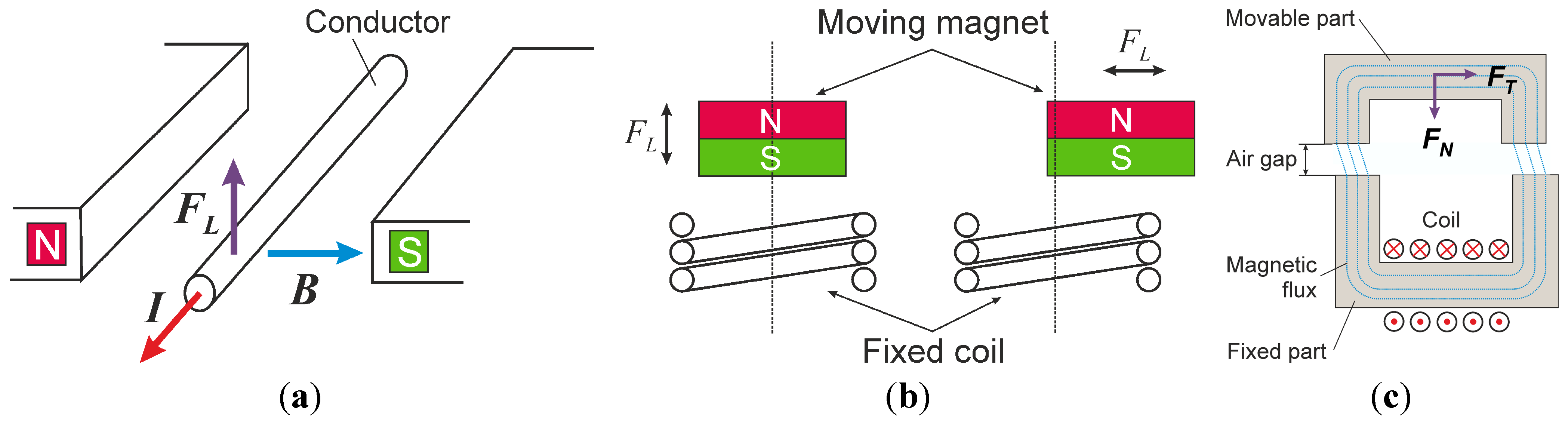
The electrodynamic actuation principle is based on the generation of the Lorentz force on a current-carrying conductor due to a magnetic field (Figure 1a). In case of a permanent magnet excited motor, the Lorentz force results from the interaction of the permanent magnet with the magnetic field of a coil. The direction of the generated electromagnetic force depends on the relative orientation of the flux density of the permanent magnet and the direction of the electric current. Hence, the electrodynamic motor concept enables force generation in two directions: levitation force and propelling force [16] (Figure 1b). Two design options are possible: the moving coil approach (fixed magnet) and the moving magnet approach (fixed coil; Figure 1b).
The variable reluctance (VR) force motor principle is based on the generation of a force due to minimization of the magnetic resistance (reluctance). The reluctance force results from the interaction between surfaces of different permeability, whereby a normal force (FN) and a tangential force (FT) component can be distinguished (Figure 1c). In principle, the normal forces are much larger than the tangential forces, which cause a linear or rotatory movement. This aspect needs to be handled carefully in the design of variable reluctance micromotors, because VR-motor concepts with a single gap suffer from high additional friction caused by the drive itself [17].
In our work, both the VR principle and the electrodynamic principle have been used to design linear and rotational microactuators.
Figure 1.
Magnetic actuation principles: (a) Lorentz force on current-carrying conductor; (b) moving magnet approach of permanent magnet excited motor; and (c) variable reluctance (VR) principle.
Figure 1.
Magnetic actuation principles: (a) Lorentz force on current-carrying conductor; (b) moving magnet approach of permanent magnet excited motor; and (c) variable reluctance (VR) principle.
3. Fabrication Technologies
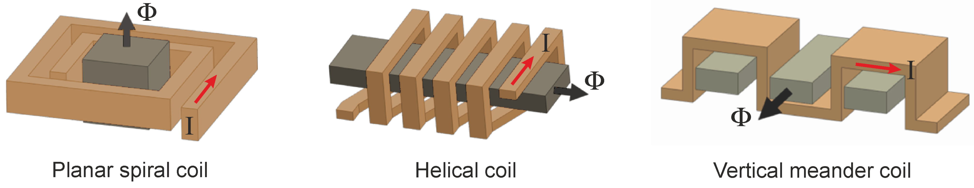
As explained above, the essential components of electromagnetic micromotors include three-dimensional microcoils, and hard and soft magnetic microelements with three-dimensional design as well. Figure 2 depicts typical designs of microcoils applied in magnetic micromotors. Of course, other configurations are also possible. In order to confine and guide the magnetic flux soft magnetic cores have to be integrated into the coils.
Figure 2.
Typical designs of microcoils applied in magnetic micromotors (according to [18], Φ: magnetic flux, I: electric current).
Figure 2.
Typical designs of microcoils applied in magnetic micromotors (according to [18], Φ: magnetic flux, I: electric current).

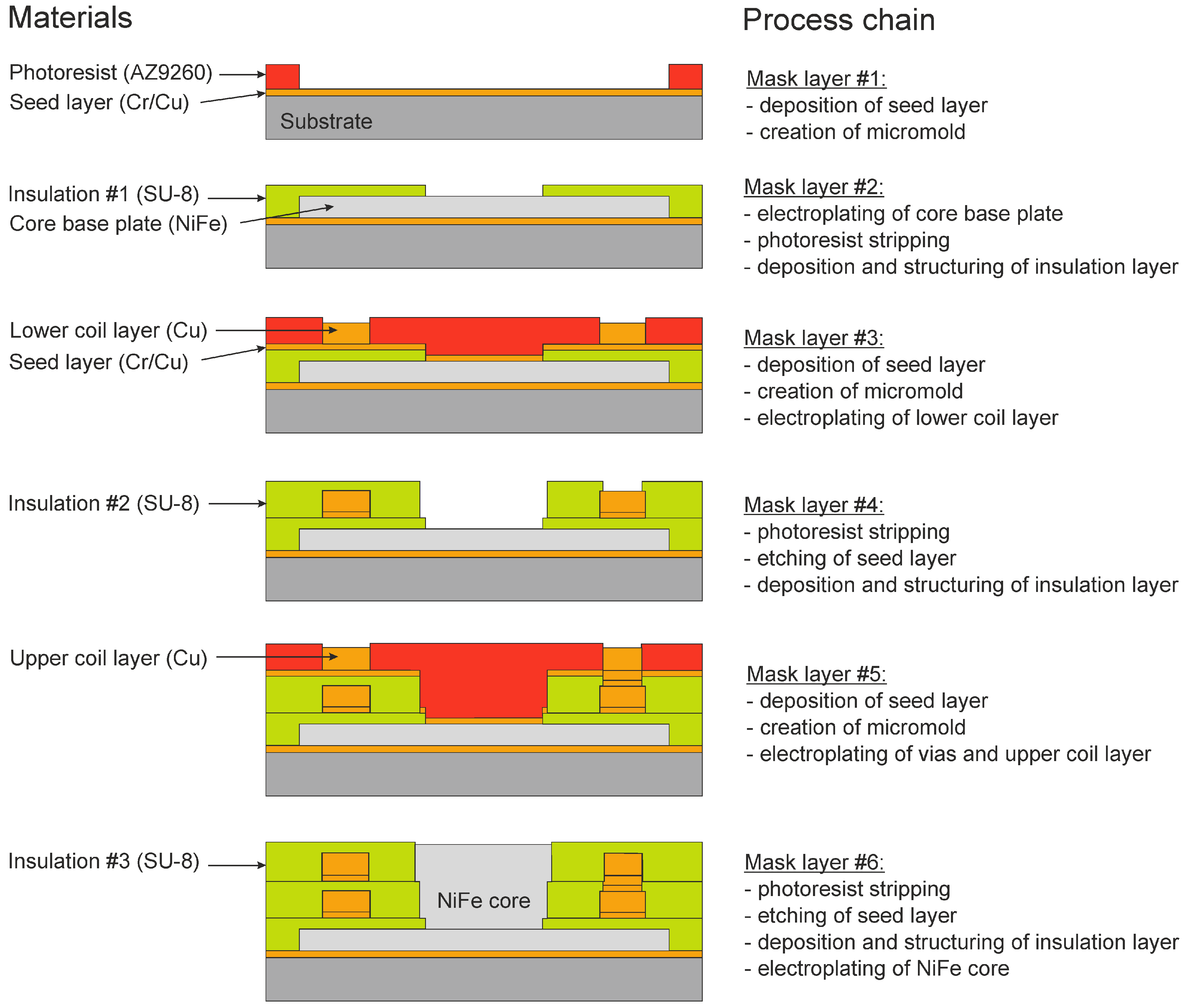
Challenging micromachining technologies have to be used for manufacturing such magnetic circuits. As an example, in Figure 3 the basic process chain for a double layer spiral microcoil with integrated NiFe core is shown in parts. There are three functional structures in these devices, each of which requires specific fabrication techniques: the current-carrying conductor coil, the soft magnetic flux guiding core, and the insulation layers which fill the gaps between coil conductors and between coil conductors and magnetic components, respectively.
Figure 3.
Basic process chain for fabrication of a double layer spiral microcoil with integrated NiFe core.
Figure 3.
Basic process chain for fabrication of a double layer spiral microcoil with integrated NiFe core.

The processes used to fabricate the microcoils comprise sputter deposition of Cr/Cu seed layers, the creation of temporary micromolds using UV depth lithography, and subsequent electroplating of the Cu conductors. The temporary micromolds were mainly made of the highly viscous diazonaphthoquinone based positive resist AZ9260. The technology was optimized to such an extent that 90 μm thick layers of resist could be processed with an aspect ratio of 12 [19]. To assure uniform coating in cases where resist had to be deposited on vertical walls, the negative electro-depositable photoresist InterVia3D-N was used [19]. The processes used to manufacture the magnetic components are similar: sputter deposition seed layers, creation of temporary micromolds out of AZ9260, and microelectroplating of NiFe. The Cu conductors as well as the soft magnetic components were embedded in insulation layers. Two insulating materials were used: the epoxy based negative photoresist SU-8 [20] and the inorganic material silicon nitride. Low-stress silicon nitride was deposited by plasma enhanced chemical vapor deposition and structured using conventional lithography and plasma etching. Cured SU-8 forms a highly cross-linked matrix of covalent bonds resulting in glass-like mechanical properties and high thermal and chemical stability. The technology was so optimized that aspect ratios of 60 in 600 μm thick resist layers could be achieved [19].
High-efficient magnetic interactions in micro-scale devices involve permanent magnets [6]. There are several possibilities to integrate hard magnetic components into micromotors: hybrid integration of permanent magnets [21], electroplating of hard magnetic materials [22], and polymer magnets, in which micro particles of hard magnetic materials are suspended in a polymer matrix [23]. In our work, we used both commercially available bulk magnets and polymer magnets. A special lift-off process for the fabrication of polymer magnets of arbitrary shape and high thickness was developed. Hard magnetic powders of ceramic ferrites (particle size about 1 μm) or rare earth alloys (particle size between 6 and 9 μm) were mixed with a polymer. The concentrations were up to 90 wt %. The pasty hard magnetic composite was then filled into SU-8 molds. Prior to this step, the non-required areas around the molds were covered with photoresist. After baking and leveling the composite structure via a polishing process, the photoresist and residual composite were removed leaving the polymer magnets in the molds. After magnetization permanent micromagnets with a residual induction of up to 300 mT and structural heights of up to 600 μm were obtained [24].
4. Designs of Electromagnetic Micromotors
Through the development and optimization of the process technologies described above the realization and application of a variety of linear and rotatory micromotors can be realized. There are two main challenges that have to be overcome. The first one is static friction. In micromotors, low lateral propulsive forces typically act under high contact pressure. Therefore, for effective operation a low friction coefficient has to be achieved. The second challenge is the heat dissipation. The increase of current density and consequently of thermal losses may affect the efficiency of operation in some way and may require appropriate cooling measures.
4.1. Linear VR Stepper Motor
The linear VR micromotor [25,26] with dimensions of about 10 mm × 10 mm comprises three or six stator systems located in parallel with vertical meander coils wound around the in-plane toothed soft magnetic poles, thus producing an horizontal magnetic flux. The comb shaped poles of the traveler extend in between the stator poles. The attractive normal forces are compensated due to two complementary gaps with nominal dimensions of 8 μm between stator and traveler. The tooth pitch is 100 μm resulting in steps of 33.3 μm or 16.7 μm over a traverse path of 3.5 mm. Friction forces are overcome by a passive magnetic guidance shifting the traveler in vertical direction by a small amount. An overall thrust of 1 mN @ 3 A was measured. An unfavorable effect is the high temperature of about 160 °C during continuous excitation of the motor at 2.5 A. Therefore, an active cooling of the motor is mandatory.
The force of VR motors can be increased by integration of additional permanent magnets into the traveler. Such a hybrid microstep motor was successfully designed and fabricated by Hansen and Gatzen from Hanover University [27].
4.2. Rotatory VR Stepper Motor
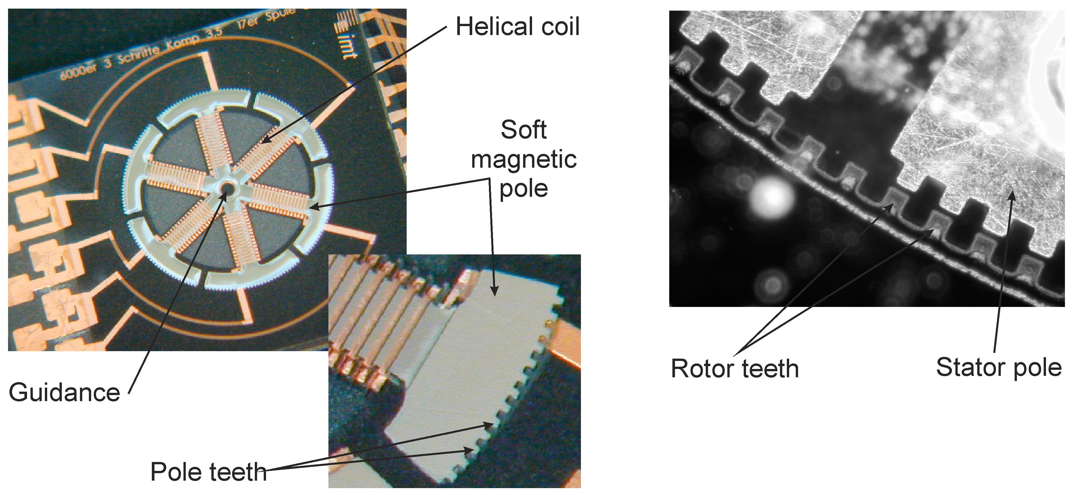
The rotatory VR micromotor [26,28] is designed as an external rotor motor. The rotor consists of 6 or 12 soft magnetic pole shoes, which feature a toothed structure on the outer circumference. A helical coil of about ten turns is wrapped around each pole shoe. Two opposite coils are connected to the same electrical phase inducing a horizontal magnetic flux. The magnetic circuit is closed via the soft magnetic rotor yoke, which is also toothed, and the air gap (3 μm) between stator and rotor. Due to the complementary configuration of the air gaps and a centrically arranged guidance the normal forces are compensated. Sequential activation of the pole arms results in a continuous rotatory movement of 21 rpm with discrete steps due to the tangential reluctance forces. The tooth pitch is 100 μm resulting in step width of 33.3 μm or 16.7 μm which correspond to incremental rotation angles of 0.64° and 0.32° for a rotor diameter of 8 mm. Figure 4 illustrates the concept of the rotatory VR micromotor. An overall torque of 0.3 μN·m @ 0.9 A has been measured. Thermographic measurements revealed a maximum temperature of 60 °C @ 0.9 A requiring an active cooling of the motor.
Figure 4.
Rotatory VR stepper motor configuration: (left) Stator; (right) External rotor topology. Reprinted with permission from [26], Copyright 2011 Springer Science + Business Media.
Figure 4.
Rotatory VR stepper motor configuration: (left) Stator; (right) External rotor topology. Reprinted with permission from [26], Copyright 2011 Springer Science + Business Media.

A crucial issue, which has to be taken into account when designing VR micromotors, is the experimental finding that the permeability of the electroplated NiFe layers varies with the layer height [29]. The most likely cause for this behavior is the intrinsic process-related stress induced during film growth. This issue has to be tackled in future work.
4.3. Rotatory Synchronous Micromotor
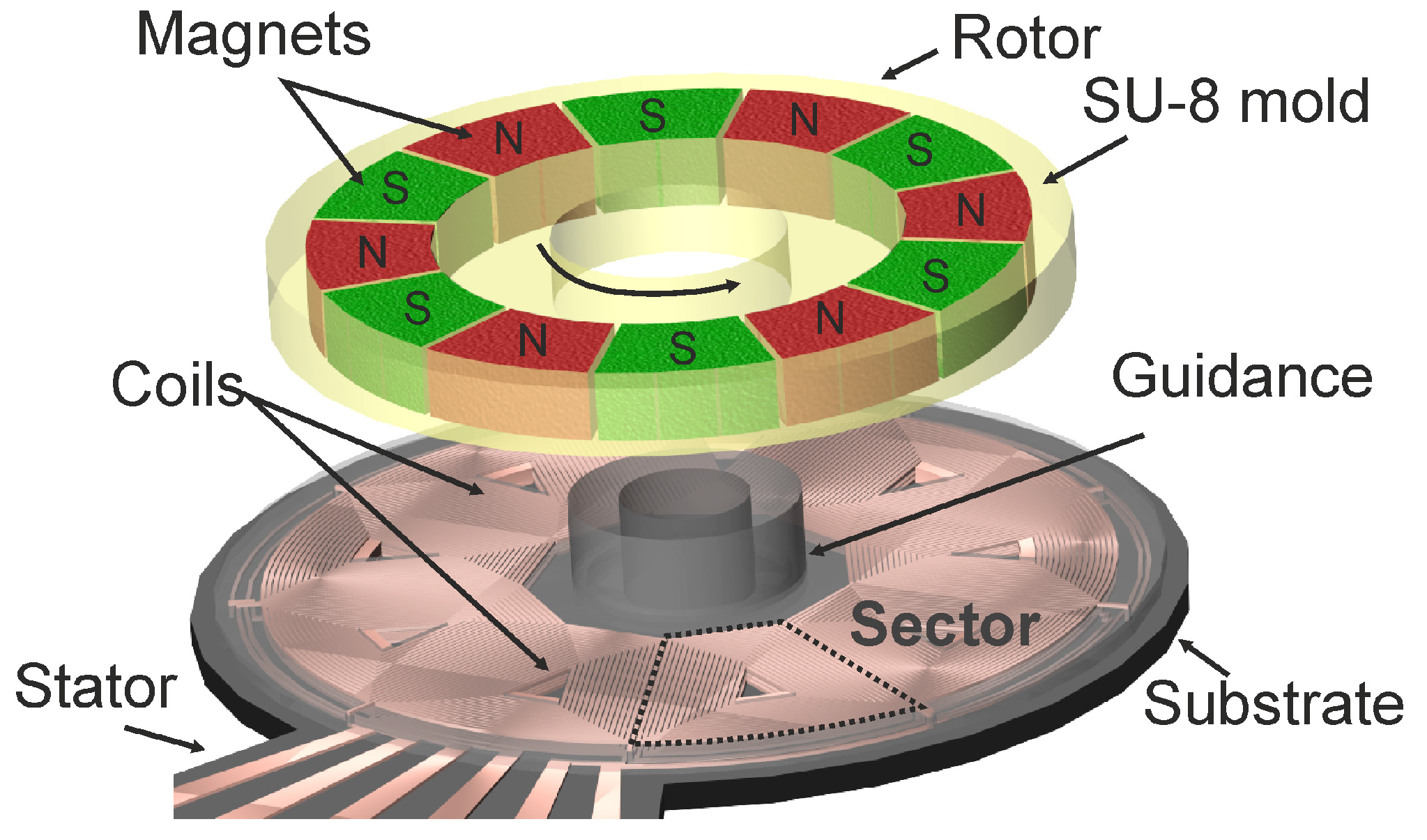
Synchronous micromotors are based on the electrodynamic actuation principle. The rotatory model [26,30] consists of a stator (diameter 1.0–5.5 mm) comprising double layer planar spiral microcoils and a rotor made of SU-8 molds containing permanent magnets with alternating axial magnetizations. The magnets are either polymer magnets or commercial sintered magnets. The configuration of the coils (three or six phases) and magnets allows rotation in continuous and stepping modes up to 7000 rpm. The maximum temperature of 32 °C at 100 mA does not require an active cooling. The measured torque varies by one order of magnitude between motors with polymer magnets (<1.2 μN·m @ 70 mA) and motors with sintered magnets (<10 μN·m @ 70 mA). Figure 5 illustrates the concept of the rotatory synchronous micromotor. This result emphasizes the importance of improving the technology of integrable hard magnetic components.
4.4. Linear Synchronous Micromotor
The linear synchronous micromotors [31] consist of stators designed as three-strand systems with three to 15 spiral coils per strand resulting in step widths of 100 to 533 μm over a traverse path of about 9 mm. The travelers contain permanent magnets with alternating axial magnetization. Sintered magnets as well as polymer magnets are used. The maximum thrust achieved for stepping mode is 283 μN at 100 mA.
Figure 5.
Concept of rotatory synchronous micromotor. Reprinted with permission from [30], Copyright 2008 International Frequency Sensor Association.
Figure 5.
Concept of rotatory synchronous micromotor. Reprinted with permission from [30], Copyright 2008 International Frequency Sensor Association.

4.5. Plunger Coil and Linear Lorentz Force Microactuators
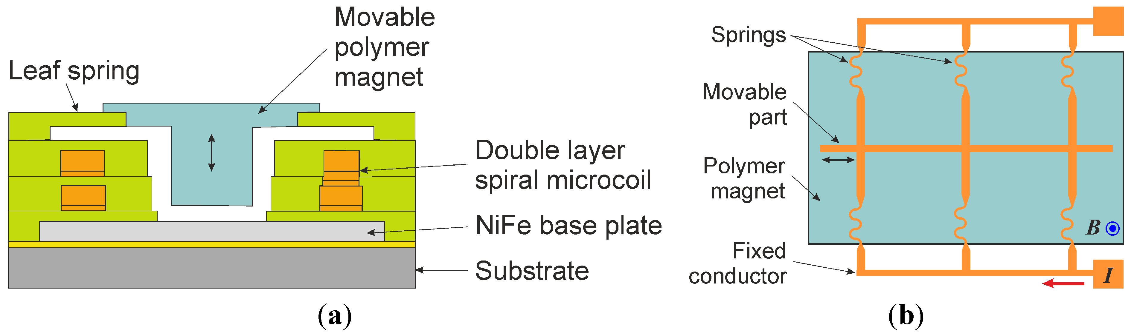
Besides the VR and synchronous micromotors the developed technologies have been used to design two other types of magnetic microactuators with integrated polymer magnets: a plunger coil actuator and a linear Lorentz force actuator [19,24,32]. The plunger coil actuator with dimensions of 8 mm × 8 mm consists of a polymer magnet suspended by SU-8 spring leaves inside a double layer micro coil (Figure 6a). The deflection can reach up to 200 μm. Measurements revealed a force of 0.8 mN @ 300 mA. The linear Lorentz force microactuator consists of electroplated copper structures, which are partially deposited on a sacrificial layer (Figure 6b). After etching the sacrificial layer movable conductors are located above a polymer magnet. The movable part is suspended by springs, which are attached to the fixed part of the conductor and ensure the reset force. Forces of up to 1.2 mN and deflections of up to 100 μm were achieved at currents of up to 1 A. Resistances of the conductors range from 30 to 60 mΩ resulting in power consumptions between 30 and 60 mW.
Figure 6.
Schematic views of magnetic microactuators (according to [32]): (a) plunger coil actuator and (b) linear Lorentz force actuator.
Figure 6.
Schematic views of magnetic microactuators (according to [32]): (a) plunger coil actuator and (b) linear Lorentz force actuator.

5. Applications
There are two main areas of application for electromagnetic micromotors: microfluidic systems and x-y positioning systems. So-called lab-on-chip systems integrate one or more laboratory processes onto a chip with dimensions of a few square centimeters. These systems are based on different microfluidic platforms, and they make accessible many new applications in biomedicine, pharmaceutics and biotechnology. Most microfluidic platforms utilize pressure gradients for fluid transport, which are usually generated by external pumps. The use of micropumps, which can be integrated into the microfluidic chip, improves the portability of the system as well as the compatibility with the liquid volumes to be managed. In addition, often other microfabricated components, for example microvalves, can be applied to fluid handling in lab-on-chip systems.
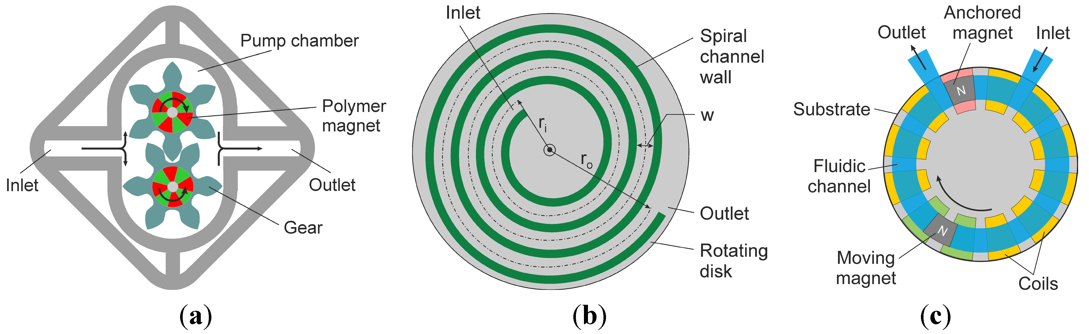
The rotatory synchronous motor principle has been applied as driving mechanism of several active microfluidic components. The micro gear pump (Figure 7a) was realized by combining two synchronous motors in the square pump chamber of side length 7.5–10 mm and height of 300 μm, which is made of SU-8 [33]. Teeth with involute shape are placed on the outer diameter of the rotors forming gears. One gear is driven by excitation of the motor and actuates the other gear to rotate in opposite direction. Typically only one gear is driven. However, in order to reduce the driving current, both gears can be driven. Due to the rotation of the gears the fluid is drawn from the inlet and transported to the outlet. A pump rate of 150 mL/min (H2O) at 150 rpm was achieved. The spiral channel viscous micropump [34,35] comprises a rotating spiral channel disk, which is driven by the synchronous micromotor, a flat cover, and fluid inlet and outlet ports. The rotating spiral channel disk (Figure 7b) has a diameter of 4.5 mm. The spiral channel has the following dimensions: width w = 400 μm, height 800 μm, inner radius ri = 1090 μm, outer radius ro = 1770 μm. The spiral channel disk rotates in close proximity to the flat cover, thus creating a flow between the rotating element and the stationary surface of the cover. A pump rate of 1023 μL/min (H2O) at 4500 rpm was obtained. The synchronous electromagnetic micropump (Figure 7c) is based on controlling the movement of two permanent magnets in a fluidic channel by a set of planar spiral coils in order to obtain a pumping effect [36]. The channel dimensions are: width 1500 μm, height 813 μm, inner diameter 5.55 mm, outer diameter 8.55 mm. One magnet is anchored between the inlet and the outlet acting as a valve, while the other magnet is moving clockwise through the fluidic channel, thus achieving a pumping effect. As the moving magnet reaches the outlet, the two magnets change their role. This micropump is suitable for pumping fluids containing particles, which are sensitive to shear-stresses, since it can be run at low shear stresses far below the lytic values of many living cells [37]. A pump rate of 159 μL/min (H2O) at 83 rpm was achieved. This pump design can be extended to a multifunction pumping and mixing device by integration of microvalves, for example microvalves based on the plunger coil microactuator described above [38]. Homogenization of cell suspension in microbioreactors, which are used to screen microorganisms with respect to reaction kinetics, can be improved with an integrated microstirrer, similar to commonly used bioreactors on the macroscale. A synchronous micromotor has been adapted to be applied as a microstirrer in a microbioreactor. The stator is covered with the reactor vessel (height 550 μm) made of PDMS (polydimethylsiloxane). The rotor, which possesses flat panels at its perimeter and resembles a macro-scale disk stirrer, contains alternating magnets with axial magnetization [35]. First cultivation experiments proved successful working of the microbioreactor over a time period of approximately 10 h with constant stirring.
Miniaturized x-y positioning systems will be increasingly needed to facilitate positioning and manipulation tasks in micro applications, for example in biomedicine, micro metrology and micro assembly. These applications demand positioning systems, which should be able to generate displacement strokes with sub-micrometer level accuracy, high precision and high repeatability. Linear VR, hybrid or synchronous micromotors can be used to develop such miniaturized cross tables. A meso-scale prototype (Figure 8) using four miniature linear synchronous motors has been described by Khan et al. [39]. The positioning stage (80 mm × 80 mm) is able to perform variable strokes up to 2 mm in the x-y plane. In closed loop operation, the maximum precision errors in short (<100 μm) and long strokes are found to be 0.03 μm and 0.45 μm, respectively. An x-y micro- and nano-positioner utilizing four linear VR micromotors has been presented by Hansen and Gatzen from Hanover University [27].
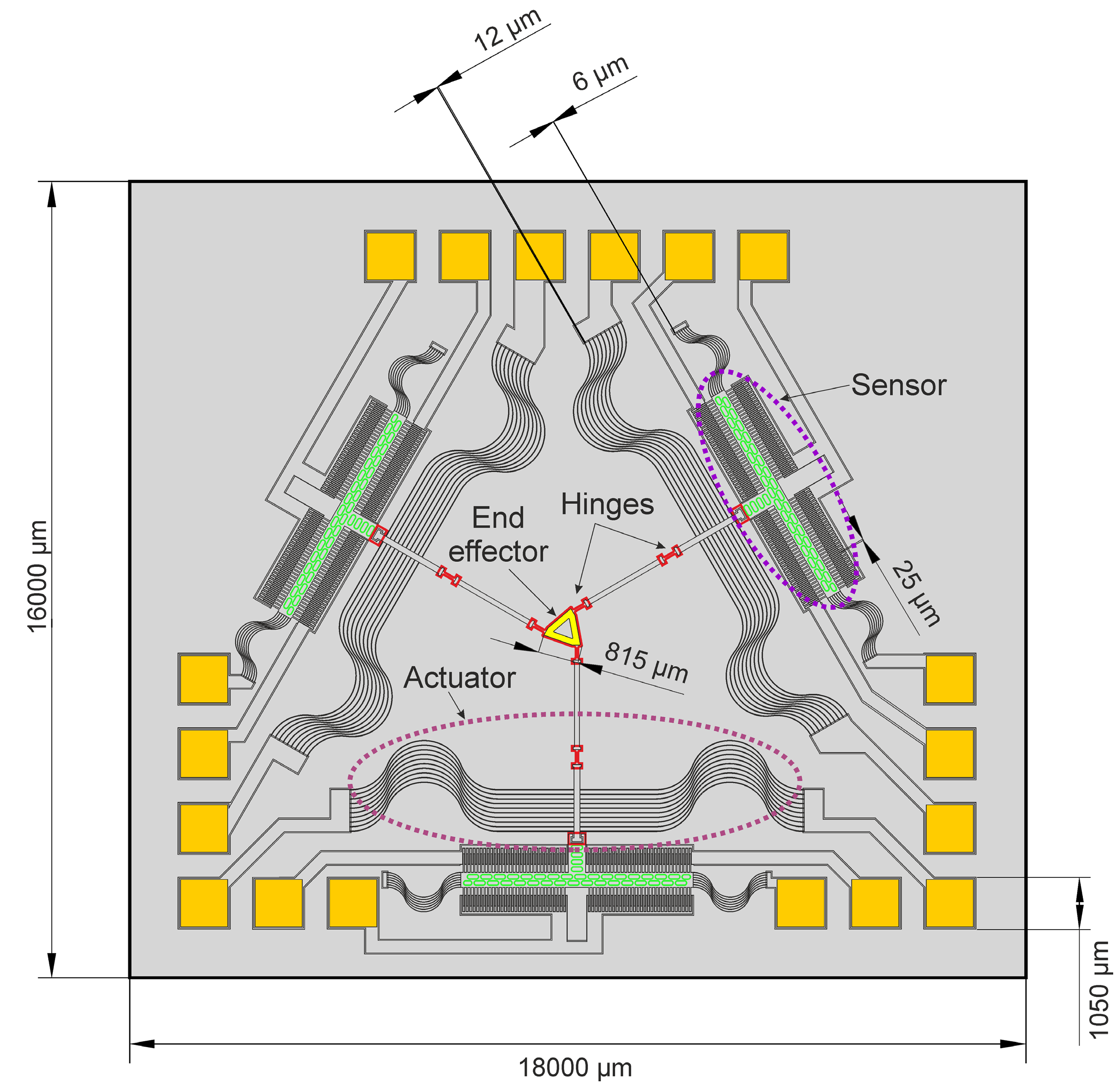
A different approach has been followed by Feldmann et al. [24]. By integration of three linear Lorentz force actuators together with capacitive position sensors a microrobot with dimensions 16 mm × 18 mm was designed (Figure 9). Each actuator is connected by polymer flexural hinges to the end effector, a triangular frame in the center of the device. The microrobot features three degrees of freedom, x- and y-motion as well as rotation of the end effector about the z-axis. The capacitive position sensors consist of comb-like structures constituting differential capacitors. In closed loop operation the end effector can be controlled with high precision of a few nanometers within a workspace of 400 μm × 400 μm [40]. Recently, an interesting application has been presented by Tang et al. [41]. They developed an omnidirectional microrobot with three wheels each driven by an electromagnetic micromotor.
Figure 7.
Schematics of micro pumps: (a) micro gear pump (according to [33]); (b) spiral channel viscous micropump (according to [34]); and (c) synchronous electromagnetic micropump (according to [36]).

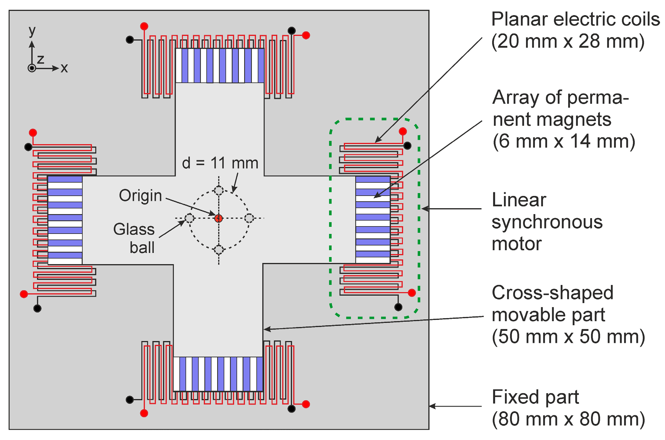
Figure 9.
Microrobot concept (according to [42]).
Figure 9.
Microrobot concept (according to [42]).
6. Conclusion and Outlook for the Future
The development of electromagnetic microactuators is still in its initial phase. The results presented here clearly show their great potential for application in microelectromechanical systems. Applying electromagnetic actuation principles in microfluidic platforms can open up new possibilities for the development of multifunctional fluidic systems. Also, electromagnetic microactuation offers new applications in the fields of micropositioning and microrobots. However, there are still technological challenges which have to be tackled, among others the improvement of the magnetic properties of electroplated soft magnetic layers, the development of effective techniques for the integration of hard magnetic elements, and the implementation of appropriate active cooling measures where applicable.
Acknowledgments
The work reviewed has been funded by the German research Foundation (DFG) and the Federal Ministry of Education and Research (BMBF). The author gratefully acknowledges financial support of the Volkswagen foundation.
Conflicts of Interest
The author declares no conflict of interest.
References
- Fan, L.S.; Tai, Y.C.; Muller, R.S. IC-processed electrostatic micromotors. Sens. Actuators 1989, 20, 41–47. [Google Scholar] [CrossRef]
- Mehregany, M.; Nagarkar, P.; Senturia, S.D.; Lang, J.H. Operation of microfabricated harmonic and ordinary side-drive motors. In Proceedings of the IEEE Workshop on Micro Electro Mechanical Systems, Nappa Valley, CA, USA, 11–14 February 1990; pp. 1–8.
- Bart, S.F.; Lober, T.A.; Howe, R.T.; Lang, J.H.; Schlecht, M.F. Design considerations for micromachined electric actuators. Sens. Actuators 1988, 14, 269–292. [Google Scholar]
- Trimmer, W.S.N.; Gabriel, K.J. Design considerations for a practical electrostatic micro-motor. Sens. Actuators 1987, 11, 189–206. [Google Scholar] [CrossRef]
- Busch-Vishniac, I.J. The case for magnetically driven microactuators. Sens. Actuators A 1992, 33, 207–220. [Google Scholar] [CrossRef]
- Cugat, O.; Reyne, G.; Delamare, J.; Rostaing, H. Novel magnetic micro-actuators and systems (MAGMAS) using permanent magnets. Sens. Actuators A 2006, 129, 265–269. [Google Scholar] [CrossRef]
- Judy, J.W. Microelectromechanical systems (MEMS): Fabrication, design and applications. Smart Mater. Struct. 2001, 10, 1115–1134. [Google Scholar] [CrossRef]
- Becker, E.W.; Ehrfeld, W.; Hagmann, P.; Maner, A.; Münchmeyer, D. Fabrication of microstructures with high aspect ratios and great structural heights by synchrotron radiation lithography, galvanoforming and plastic moulding (LIGA process). Microelectron. Eng. 1986, 4, 35–56. [Google Scholar] [CrossRef]
- Guckel, H.; Skrobis, K.J.; Christenson, T.R.; Klein, J.; Han, S.; Choi, B.; Lovell, E.G.; Chapman, T.W. Fabrication and testing of the planar magnetic micromotor. J. Micromech. Microeng. 1991, 1, 135–138. [Google Scholar] [CrossRef]
- Guckel, H.; Christenson, T.R.; Skrobis, K.J.; Jung, T.S.; Klein, J.; Hartojo, K.V.; Widjaja, I. A first functional current excited planar rotational magnetic micromotor. In Proceedings of the IEEE Workshop on Micro Electro Mechanical Systems, Fort Lauderdale, FL, USA, 7–10 February 1993; pp. 7–11.
- Wagner, B.; Kreutzer, M.; Benecke, W. Linear and rotational magnetic micromotors fabricated using silicon technology. In Proceedings of the IEEE Workshop on Micro Electro Mechanical Systems, Travemünde, Germany, 4–7 February 1992; pp. 183–189.
- Ahn, C.H.; Kim, Y.J.; Allen, M.G. A planar variable reluctance magnetic micromotor with fully integrated stator and coils. J. Microelectromech. Syst. 1993, 2, 165–173. [Google Scholar] [CrossRef]
- Cho, H.J.; Ahn, C.H. Magnetically-driven bi-directional optical microscanner. J. Micromech. Microeng. 2003, 13, 383–389. [Google Scholar] [CrossRef]
- Taylor, W.P.; Brand, O.; Allen, M.G. Fully integrated magnetically actuated micromachined relays. J. Microelectromech. Syst. 1998, 7, 181–191. [Google Scholar] [CrossRef]
- Zahn, M. Derivation of the Korteweg-Helmholtz electric and magnetic force densities including electrostriction and magnetostriction from quasistatic Poynting’s theorem. In Proceedings of the IEEE Conference on Electrical Insulation and Dielectric Phenomena, Kansas City, MO, USA, 15–18 October 2006; pp. 186–189.
- Compter, J.C. Electro-dynamic planar motor. Precis. Eng. 2004, 28, 171–180. [Google Scholar]
- Gatzen, H.H.; Stölting, H.D.; Büttgenbach, S.; Dimigen, H. Novel variable reluctance micromotor for linear actuation. In Proceedings of Actuator 2000, Bremen, Germany, 19–21 June 2000; Volume 2, pp. 363–366.
- Kohlmeier, T.; Seidemann, V.; Büttgenbach, S.; Gatzen, H.H. An investigation on technologies to fabricate microcoilsfor miniaturized actuator systems. Microsyst. Technol. 2004, 10, 175–181. [Google Scholar] [CrossRef]
- Feldmann, M. Technologien und Applikationen der UV-Tiefenlithographie: Mikroaktorik, Mikrosensorik und Mikrofluidik; Shaker Verlag: Aachen, Germany, 2007. (In German) [Google Scholar]
- Lorenz, H.; Despont, M.; Fahrni, N.; Brugger, J.; Vettiger, P.; Renaud, P. High-aspect-ratio, ultrathick, negative-tone near-UV photoresist and its applications for MEMS. Sens. Actuators A 1998, 64, 33–39. [Google Scholar] [CrossRef]
- Wagner, B.; Benecke, W. Microfabricated actuator with moving permanent magnet. In Proceedings of the IEEE Workshop on Micro Electro Mechanical Systems, Nara, Japan, 30 January–3 February 1991; pp. 27–32.
- Cho, H.J.; Ahn, C.H. A bidirectional magnetic microactuator using electroplated permanent magnet arrays. J. Microelectromech. Syst. 2002, 11, 78–84. [Google Scholar] [CrossRef]
- Lagorce, L.K.; Brand, O.; Allen, M.G. Magnetic microactuators based on polymer magnets. J. Microelectromech. Syst. 1999, 8, 2–9. [Google Scholar] [CrossRef]
- Feldmann, M.; Büttgenbach, S. Novel microrobots and micromotors using Lorentz force driven linear microactuators based on polymer magnets. IEEE Trans. Magn. 2007, 43, 3891–3895. [Google Scholar] [CrossRef]
- Feldmann, M.; Büttgenbach, S. Linear variable reluctance (VR) micro motors with compensated attraction force: concept, simulation, fabrication and test. IEEE Trans. Magn. 2007, 43, 2567–2569. [Google Scholar] [CrossRef]
- Waldschik, A.; Feldmann, M.; Seidemann, V.; Büttgenbach, S. Development and fabrication of electromagnetic microactuators. In Design and Manufacturing of Active Microsystems; Büttgenbach, S., Burisch, A., Hesselbach, J., Eds.; Springer: Heidelberg, Germany, 2011; pp. 207–224. [Google Scholar]
- Hansen, S.; Gatzen, H.H. Development and fabrication of linear and multi-axis microactuators. In Design and Manufacturing of Active Microsystems; Büttgenbach, S., Burisch, A., Hesselbach, J., Eds.; Springer: Heidelberg, Germany, 2011; pp. 225–244. [Google Scholar]
- Waldschik, A.; Feldmann, M.; Büttgenbach, S. Rotatory variable reluctance (VR) micro motors: Concept, simulation, fabrication and test. In Proceedings 11th International Conference on New Actuators, Bremen, Germany, 9–11 June 2008; pp. 453–456.
- Gehrking, R.; Demmig, S.; Ponick, B.; Feldmann, M.; Büttgenbach, S. A micro linear motor with integrated passive magnetic guidance. In Proceedings 32nd Annual Conference of the IEEE Industrial Electronics Society, Paris, France, 6–10 November 2006; pp. 1245–1250.
- Waldschik, A.; Feldmann, M.; Büttgenbach, S. Novel synchronous linear and rotatory micro motors based on polymer magnets with organic and inorganic insulation layers. Sens. Transducers J. 2008, 3, pp. 3–13. Available online http://www.sensorsportal.com/HTML/DIGEST/P_SI_51.htm (accessed on 22 October 2014).
- Waldschik, A. Elektromagnetische Mikroaktoren—Konzepte, Herstellung, Charakterisierung und Anwendungen; Shaker Verlag: Aachen, Germany, 2010. (In German) [Google Scholar]
- Feldmann, M.; Büttgenbach, S. Novel versatile electro magnetic micro actuators with integrated polymer magnets: Concept, fabrication and test. In Proceedings 10th International Conference on New Actuators, Bremen, Germany, 14–16 June 2006; pp. 709–712.
- Waldschik, A.; Büttgenbach, S. Micro gear pump with internal electromagnetic drive. Microsyst. Technol. 2010, 16, 1581–1587. [Google Scholar] [CrossRef]
- Al-Halhouli, A.T. Recent advances in on-disk viscous micropumps. J. Microelectron. Electron. Packag. 2009, 6, 240–249. [Google Scholar]
- Al-Halhouli, A.; Demming, S.; Waldschik, A.; Büttgenbach, S. Implementation of synchronous micromotor in developing integrated microfluidic systems. Micromachines 2014, 5, 442–456. [Google Scholar] [CrossRef]
- Al-Halhouli, A.T.; Kilani, M.I.; Waldschik, A.; Phataralaoha, A.; Büttgenbach, S. Development and testing of a synchronous micropump based on electroplated coils and microfabricated polymer magnets. J. Micromech. Microeng. 2012, 22. [Google Scholar] [CrossRef]
- Kilani, M.I.; Al-Halhouli, A.T.; Büttgenbach, S. Shear stress analysis in a ferrolfuidic magnetic micropump. Nanoscale Microscale Thermophys. Eng. 2011, 15, 1–15. [Google Scholar] [CrossRef]
- Feldmann, M.; Demming, S.; Lesche, C.; Büttgenbach, S. Novel electro magnetic micro pump. Proc. SPIE 2007, 6799. [Google Scholar] [CrossRef]
- Khan, M.U.; Bencheikh, N.; Prelle, C.; Lamarque, F.; Beutel, T.; Büttgenbach, S. A long stroke electromagnetic xy positioning stage for micro applications. Trans. Mechatron. 2012, 17, 866–875. [Google Scholar] [CrossRef]
- Büttgenbach, S.; Feldmann, M. Electromagnetic parallel microrobot for micro- and nano-handling. In Proceedings 17th IFAC World Congress, Seoul, Korea, 6–11 July 2008; pp. 12757–12762.
- Tang, X.; Zhang, D.; Li, Z.; Chen, J. An omni-directional wall-climbing microrobot with magnetic wheels directly integrated with electromagnetic micromotors. Int. J. Adv. Robot. Syst. 2012, 9. [Google Scholar] [CrossRef]
- Boese, C.; Feldmann, M.; Büttgenbach, S. Closed-loop control for a parallel microrobot based on integrated capacitive position sensors. In Proceedings 10th International Symposium Measurement and Quality Control, Osaka, Japan, 5–9 September 2010; pp. F5-022:1–F5-022:4.
© 2014 by the authors; licensee MDPI, Basel, Switzerland. This article is an open access article distributed under the terms and conditions of the Creative Commons Attribution license (http://creativecommons.org/licenses/by/4.0/).
Share and Cite
MDPI and ACS Style
Büttgenbach, S. Electromagnetic Micromotors—Design, Fabrication and Applications. Micromachines 2014, 5, 929-942. https://doi.org/10.3390/mi5040929
AMA Style
Büttgenbach S. Electromagnetic Micromotors—Design, Fabrication and Applications. Micromachines. 2014; 5(4):929-942. https://doi.org/10.3390/mi5040929
Chicago/Turabian StyleBüttgenbach, Stephanus. 2014. "Electromagnetic Micromotors—Design, Fabrication and Applications" Micromachines 5, no. 4: 929-942. https://doi.org/10.3390/mi5040929