Article

Miscible Organic Solvents Soak Bonding Method Use in a PMMA Multilayer Microfluidic Device

Key Laboratory of Micro-Systems and Micro-Structures Manufacturing, Harbin Institute of Technology, Harbin 150001, China
*
Author to whom correspondence should be addressed.
Micromachines 2014, 5(4), 1416-1428; https://doi.org/10.3390/mi5041416
Submission received: 23 September 2014 / Revised: 5 December 2014 / Accepted: 5 December 2014 / Published: 10 December 2014
(This article belongs to the Special Issue Micro/Nano Fabrication)

Abstract

:
In this paper, we proposed a novel bonding technology to fabricate a microfluidic device based on Poly(methyl methacrylate) (PMMA). The method, which used chloroform and ethanol as miscible bonding solvent, can complete complex structures rapid assembly (10 min) at 40°C. A bonding strength of 267.5 N/cm2 can be achieved, while the micro channel deformation was less than 7.26%. Then we utilized this method to produce a three layers micro mixer, which included a T-shaped inlet channel and six H-shaped mixing units. Numerical simulation indicated that, the well mixing length of the mixer was only about 6 mm when Re = 10. Finally, fluorescence microscopy was used to verify mixer performance. The method provided the potential for mass production of multilayer rigid polymer microfluidic devices.

1. Introduction

Over the past decade, micro total analysis systems (μTAS) have provided emerging opportunities to achieve high performance analysis systems such as biology and medicine [1,2,3]. Due to requirements of multifunctional integration, the μTAS have developed three-dimensional or multilayer structures by using Micro-Electro-Mechanical-System (MEMS) technologies [4,5]. The polymer such as polymethyl methacrylate (PMMA), polydimethylsiloxane (PDMS) and SU-8 have replaced silicon and glass to establish microfluidic device due to their optical properties, biocompatibility and low cost [6,7,8]. Of these materials, PMMA shows particular advantage of mechanical properties and electric [9,10]. Hence, the PMMA chips fabrication has attracted intensive interest of MEMS techniques.
As an important procedure of chip assembly, bonding technology has been a hot area of research [11]. In comparison with PDMS and SU-8, it is a challenge to find a quick and easy method to seal the PMMA substrates without clogging and deformation, especially for multilayer devices. Hot-press bonding is the most commonly employed method for sealing PMMA microfluidic device [12,13]. However, the microstructures can be damaged by thermal or pressure easily, since the temperature is kept around glass transition temperature (Tglass). Two methods are often used to solve this problem: reduce the bonding pressure or temperature by using surface modification technology [14,15,16,17,18] or add embedded filler layer to protection micro structures [19,20,21]. However, even without considering the complex modification process, the thermal and pressure cannot be effectively transmitted to the middle layer, in that case leakage occurs; while removing the filler layer of multilayer devices in second method is not easy either. Other techniques of bonding of PMMA substrates have been proposed, including using microwave [22,23,24] and ultrasonic energies [25,26,27]. These methods utilize the microwave and ultrasonic energies to heat the specified area of the bonding interface, while maintain the temperature of PMMA substrate at low level, and avoid the deformation of hot-press bonding. However, these kind of methods usually need extra wave absorption medium or structures to generate enough heat in the bonding interface. Therefore, if the coated medium is uneven, the bonding cannot be guaranteed. Moreover, the waves transport and absorption could change in the multilayer devices, which is an additional uncontrollable parameter of the bonding process.
The organic solvent bonding is another basic sealing method of microfluidic devices. The PMMA surfaces become soft due to swelling, which increases the molecules mobility. The interface does not employ any different materials or adhesives but achieves bonding at low temperatures and pressure conditions. However, it is unsatisfactory here due to the possible structural damage caused by overly swelling. To reduce swelling damage, scholars proposed solvent assisted bonding method [28,29,30,31,32]. The organic solvents here are utilized for PMMA surface modification, the modified interface lead to a joint molecule diffusion zone when small pressure is applied on substrates. After solvent evaporation, there is an inseparable bonding interface. Due to only a few solvent remains the modified interface, if assembly process cannot be completed within a short time, the strength is difficult to guarantee. Moreover, if the surface modification is uneven the bonding is difficult to guarantee also.
In this paper, we presented a novel solvent soak bonding method to manufacture multilayer microfluidic device based on PMMA material. Ethanol and chloroform miscible solution were used as the bonding solvent, which dissolve the PMMA material appropriately. So the bonding interface can soak into the miscible solution for a period of time and avoid structural damage. The soak method not only can prevent leakage caused by uneven coated but also provided enough solvent to maintain polymer molecular diffusion. In addition, this method does not require expensive equipment and can realize mass production. Finally, we used the method to assemble a multilayer micromixer, and characterized the mixing efficiency improvement of 3D structures by using numerical simulation and fluorescence microscopy.

2. Experimental Section

2.1. Equipment and Materials

The PMMA substrates were cut with different thickness (3.0 and 1.5mm) and used for different layers (Stone into Gold Trading Co., Ltd., Dongguan, China). The micro structures were manufactured by micro-precision engraving machine (VIP3530, Thai Power Electronic Equipment (Beijing) Co., Ltd., Beijing, China). The ultrasonic cleaning equipment (KQ-5200DB, Kun Shan Ultrasonic Instruments Co., Ltd., Kunshan, China) was used for substrates cleaning. Vacuum oven (DZF-6020, Shanghai Jing Hong Laboratory Instrument Co., Ltd., Shanghai, China) provided moderate thermal field to complete the bonding. The microscope (C3203A, Shanghai Precision Instrument Co., Ltd., Shanghai, China) used to observe the microstructures. The reagents such as chloroform and ethanol were all AR grade (Tianjin Kermel Chemical Reagent Co., Ltd., Tianjin, China).

2.2. Bonding Procedure

Bonding PMMA substrates involved the following steps. First, the substrates were cleaned by ultrapure water in the ultrasonic cleaning equipment for 10 min to remove the tiny debris in the micro structures. The substrates were put into the oven and dried at 40 °C for 30 min. Second, the miscible solution which was composed of chloroform and ethanol was prepared. VE was the volume of ethanol and VC was the volume of chloroform. The volume ratio was VC:VE = 1:10. To ensure uniform pressure on the substrate and avoid dents caused by clips, the substrates were fixed by quartz glass fixture and four nylon screws. Because any trapped bubbles between the bonding surfaces could cause leakage and reduce the bonding strength. To avoid bubbles as much as possible, the substrates were aligned and pre-fixed, then completed assembly in the miscible solution. Moreover, this assembly approach also can avoid the bonding defects caused by solution uneven coated. If necessary, the alignment between the substrates can be finished under microscope. After assembly, the substrates were put into miscible solution, and ensured the bonding interface was immersed into the solution. The cistern was moved into the oven quickly, heated for 10 min to complete the bonding at 40 °C. To make sure the components consistent, the miscible solution must be replaced after each bonding. The microstructures were rinsed by ultrapure water immediately to remove residual miscible solution when bonding was completed. The photos of fixed PMMA substrates and the micrographs of microchannel cross section are shown in Figure 1.
Figure 1. The photos of Poly(methyl methacrylate) (PMMA) substrates and microchannel cross section. (A) Fixed PMMA substrates. (B) Cross section before bond. (C) Cross section after bond.
Micromachines 05 01416 g001

3. Results and Discussion

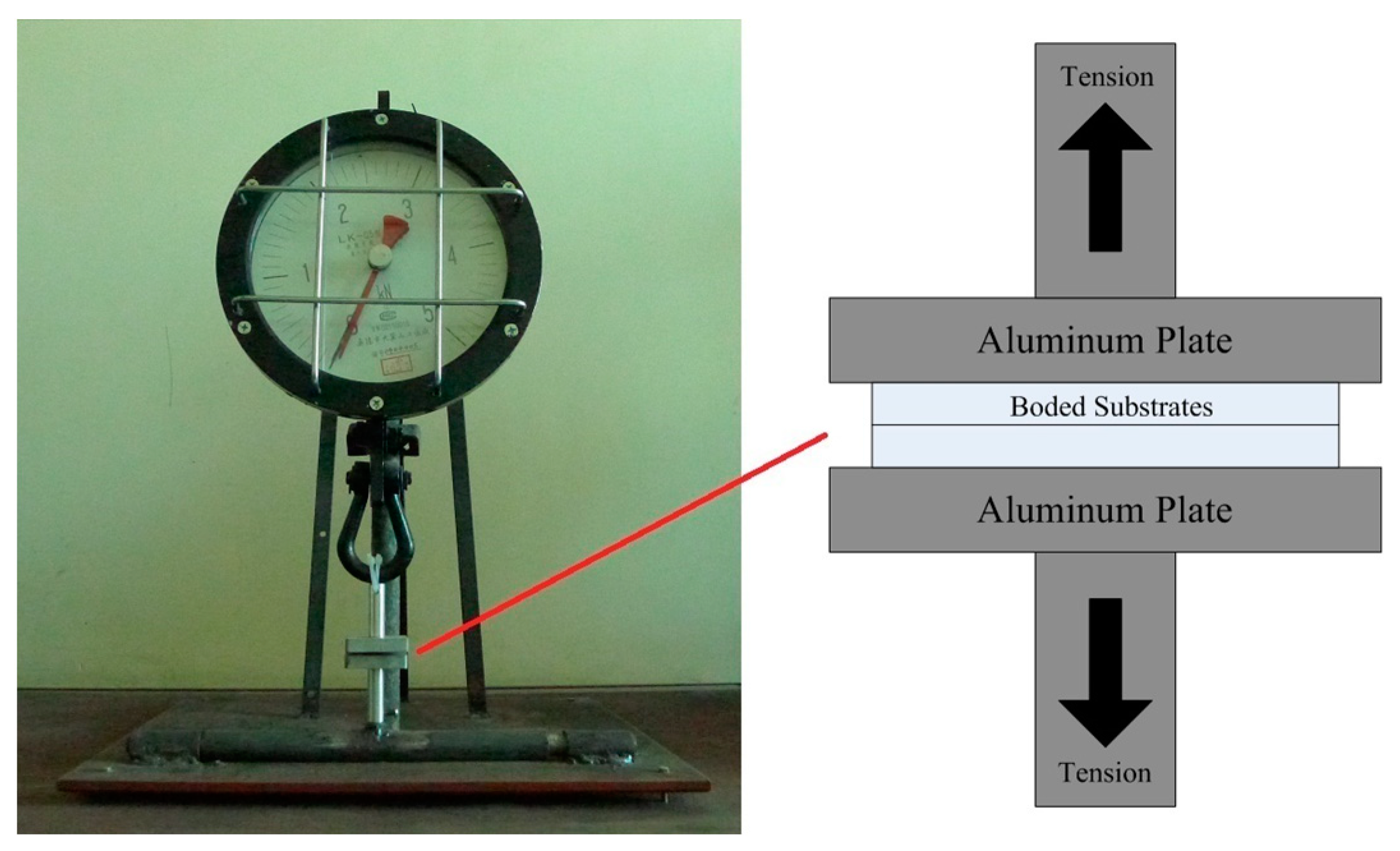
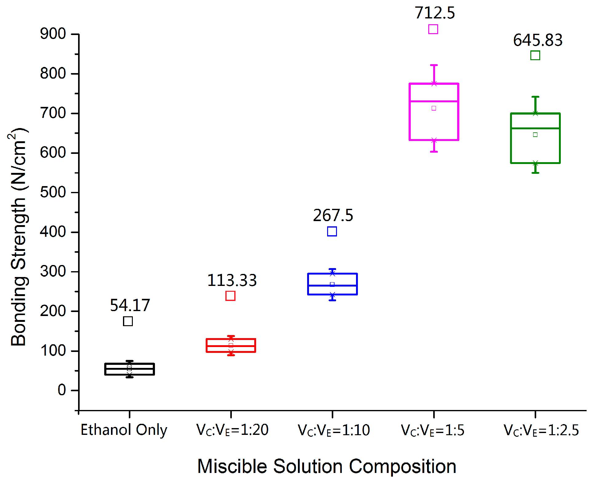
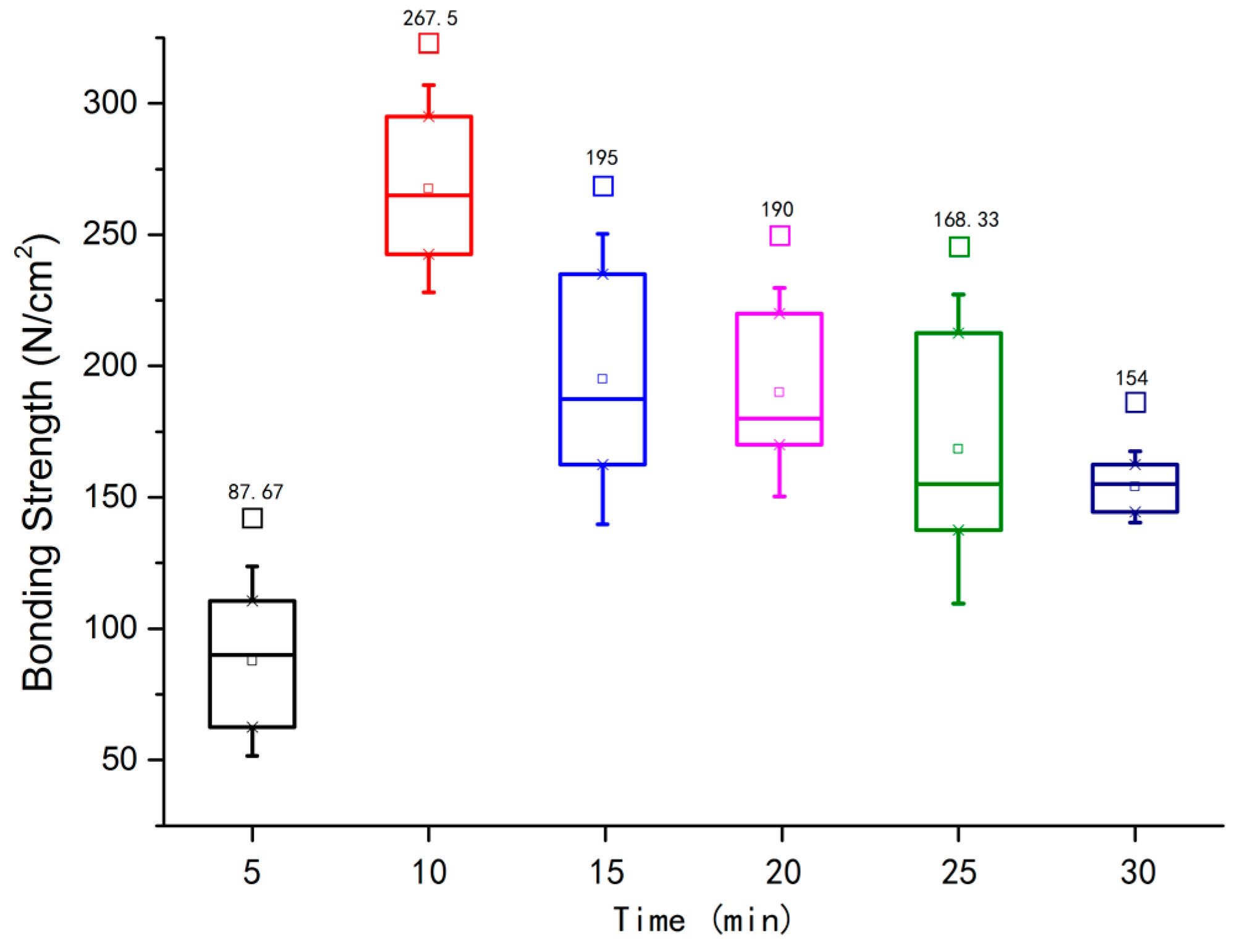
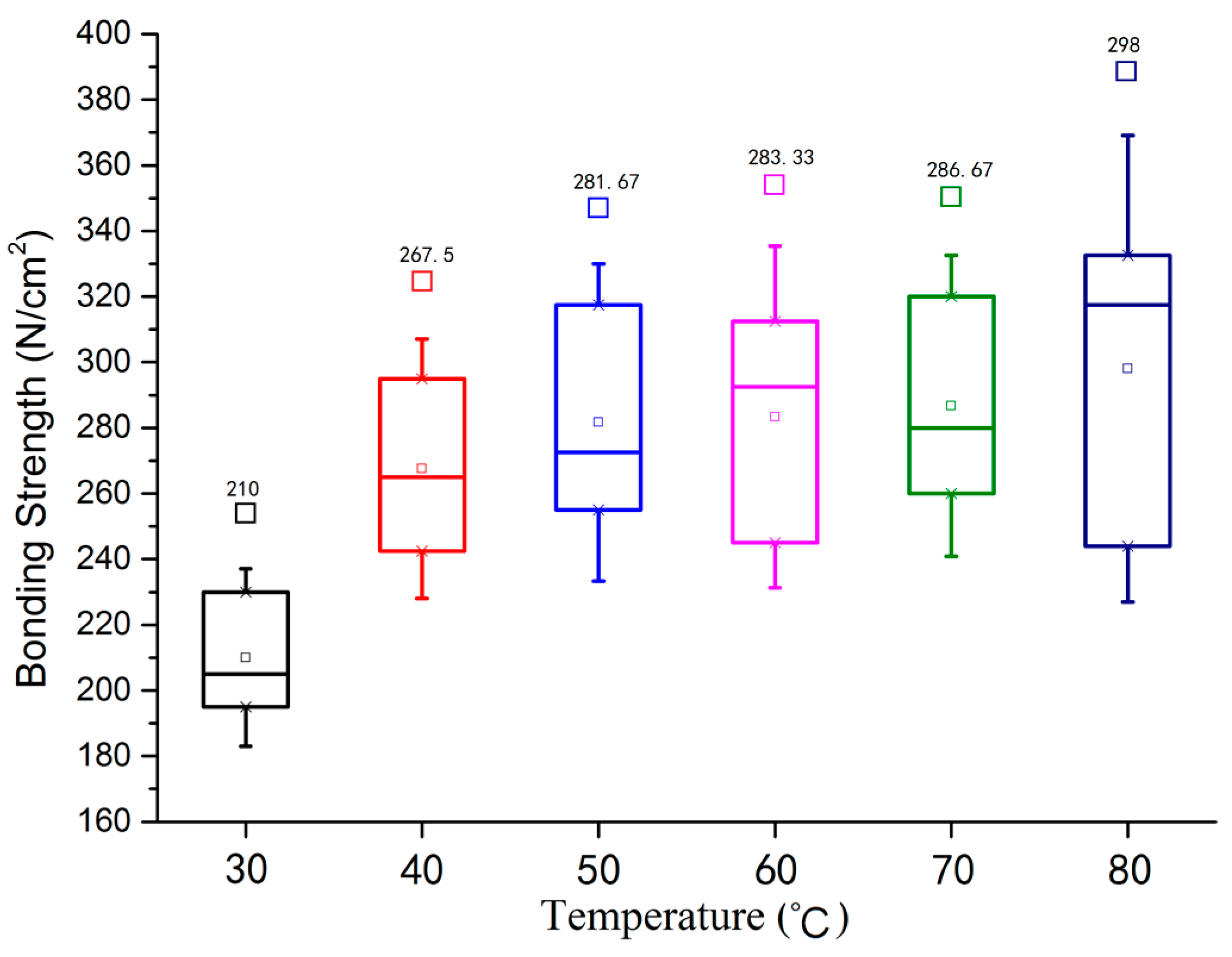
3.1. Bonding Strength

The determinants of bonding strength include: miscible solution composition, bonding time and bonding temperature. The bonded device was rest for 20 min after the oven step, when the organic solvent volatilize fully, the bonding strength was evaluated by a tensile test system (Wuxi Dajishan Instrument Engineering Equipment Co., Ltd., Wuxi, China), which is shown in Figure 2. The bonded substrate was glued to aluminum plate by the two component modified acrylate adhesive (GLH-302, Fushun GELIAHAO Chemical Co., Ltd., Fushun, China). Each measurement was repeated three times and the values were averaged.
First, we researched the effect of miscible solution composition, and the tensile test results are shown in Figure 3. Bonding could be accomplished when there was only ethanol in the solution, the bonding strength was 54.17 N/cm2. With the increasing of the volume of chloroform, the bonding strength improved and achieved the maximum strength of 712.5 N/cm2 when the volume ratio was VC:VE = 1:5 (about 13 times larger than only ethanol in the solution). However, the bonding strength began to decline, if the chloroform volume increased further. The higher content of chloroform does not helpful in promoting the bonding strength.
Figure 2. The photograph of the tensile test system and the diagram of tensile test principle.
Micromachines 05 01416 g002
Figure 3. The bonding strength of different solution composition (T = 40 °C; t = 10 min).
Micromachines 05 01416 g003
The polymer bond strength is determined by the VDW (Van der Waals’ force) of molecule and the covalent bond between atoms. The soak bonding process is related to polymer dissolution. Since the polymer molecule is much larger than the solvent molecules, when PMMA surface contact with the solvent, the solvent molecules come into the polymer. The curly chains loosen, the voids between the molecular chains become larger and the polymer volume expand. The swelling make the chains move more freely and diffuse across the interface of the two contacting surfaces. The polymer chains achieve entanglement in the diffusion layer, and the bonding is completed. Once the polymer surface swelling is not sufficient, the molecular chain movement is limited, the diffusion layer is not thick enough, the bonding strength cannot be guaranteed. With the continuous increasing of solvent molecules, the polymer begins to dissolve. The chains distance extends further and some chains begin to fracture. The force of VDW and covalent bond would decrease, and the bond strength would decline also. That is why the bonding strength in Figure 3 increased first and then decreased.
Then, we investigated the influence of bonding time. The movement and diffusion of molecular chains between bonding interfaces would take some time. In Figure 4, if the bonding time was less than 10 min, the strength was increased with the time increasing. It indicates that, polymer surface swelling is not sufficient when bonding time is less than 10 min. With immersion time increasing, the molecular chain between bond interfaces got rid of the restriction gradually, and bonding strength achieved the maximum 267.5 N/cm2 when t = 10 min. When the time exceeded 10 min, the bonding strength reduced gradually. It indicates that, as the bonding interface begins to dissolve, the distance of molecular chains increase and the VDW force decreases. Therefore, bonding time is not as long as possible.
Finally, in Figure 5, the bonding strength is proportional to temperature, similar as simple hot-press bonding (the PMMA surface without modification) [13], and the bonding strength is much higher due to the effect of miscible solution. When t = 30 °C, the bonding strength was 210 N/cm2, while the bonding strength increased to 267.45 N/cm2 when t = 40 °C. The second order transition temperature of PMMA is around 40 °C. At this temperature, the methyl side chains begin to move and participate to the diffusion layer formation. Therefore, there is a substantial increase in bond strength. Hereafter, the bonding strength improved slowly with the continuous increasing of temperature. The temperature rise can facilitate the molecular chain movement, but the improvement is not much due to its distance from the Tglass of PMMA (105 °C).
Figure 4. The bonding strength of different bonding time (VC:VE = 1:10; T = 40 °C).
Micromachines 05 01416 g004
Figure 5. The bonding strength of different bonding temperature (VC:VE = 1:10; t = 10 min).
Micromachines 05 01416 g005

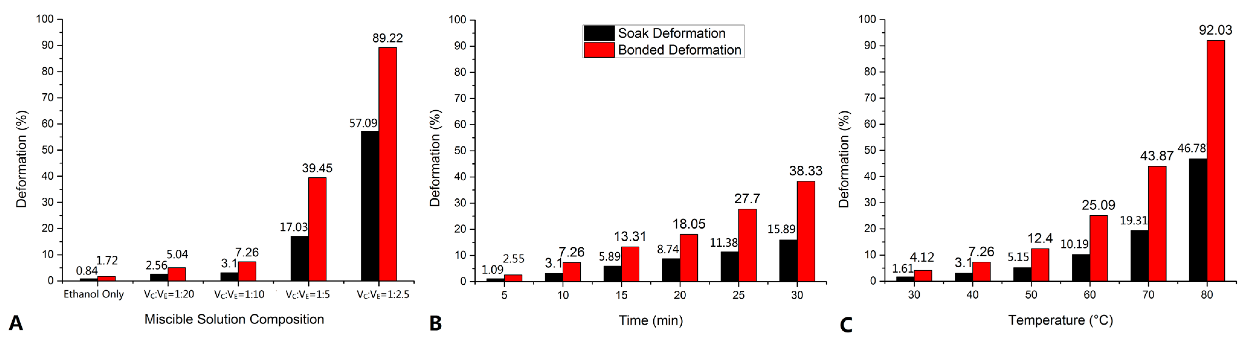
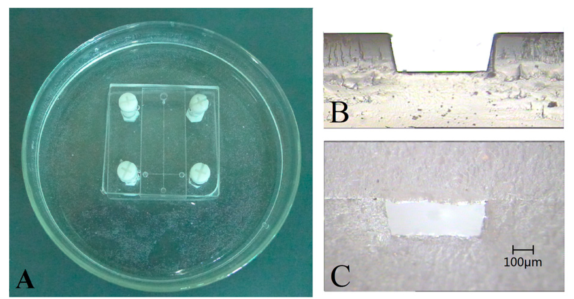
3.2. Structural Deformation

Soak deformation and bonded deformation were investigated to characterize the structural deformation. To guarantee the micro device performance, the deformation should not exceed 10%. The soak deformation DS was calculated by Equation (1):
D S = D S 0 D S 1 D S 0
where, D S 0 is the channel cross-sectional area which was measured before solvent immersion; D S 1 is the channel cross-sectional area which was measured after solvent immersion. The soak deformation is used to characterize the structure deformation, which was caused by swelling. The bonded deformation DB was calculated by Equation (2):
D B = D B 0 D B 1 D B 0
where, D B 0 is the channel cross-sectional area which was measured before bonding; D B 1 is the channel cross-sectional area which was measured after bonding. The bonded deformation is used to characterize the structure deformation, which was caused by swelling and the fixture pressure. The microchannel cross sectional was approximate isosceles trapezoid (Figure 1B), and the cross-sectional areas were calculated by open source software ImageJ. These measurements were repeated three times and the values were averaged. The deformation histograms are shown in Figure 6, the grouping conditions were consistent with tensile test.
In Figure 6A, when chloroform content of miscible solution increased from 9.1% (VC:VE = 1:10) to 16.7% (VC:VE = 1:5), the soak deformation increased from 3.1% to 17.03%, while the bonded deformation increased from 7.26% to 39.45%, the deformation began to impact on device performance. If the chloroform content was 28.57% (VC:VE = 1:2.5), the soak deformation achieved 57.09% and the bonded deformation reached 89.22%, the micro structures were damaged. In Figure 6B, with the time increase, the deformation became large gradually. When t = 15 min, DS = 5.89%, while DB = 13.31%. In Figure 6C, if T = 50 °C, DS = 5.15%, while DB = 12.4%. In addition, it was found that the bonding deformation was more than twice of soaking deformation. That is due to both side PMMA surfaces of bonding interface were swollen during bonding process, and the pressure generated by fixture made the structure height decline. Therefore, to maintain the structure morphology, the chloroform content of miscible solution should not exceed 10%, the soak time should be less than 15 min and the temperature should be less than 50 °C.
Figure 6. The deformation of microchannel under different conditions: (A) dependence of deformation on solution composition (T = 40 °C; t = 10 min); (B) dependence of deformation on bonding time (VC:VE = 1:10; t = 10 min); (C) dependence of deformation on bonding temperature (VC:VE = 1:10; T = 40 °C).
Micromachines 05 01416 g006

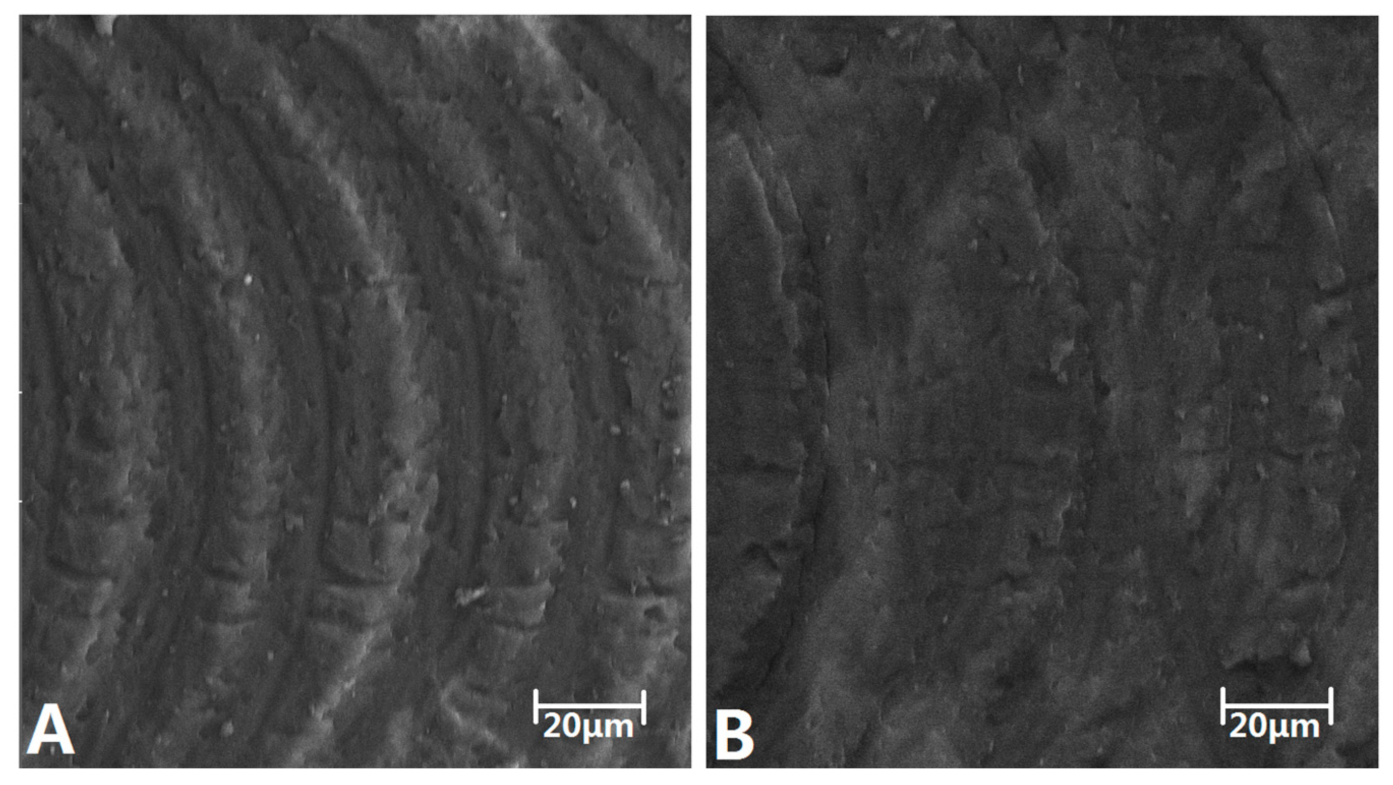
3.3. Microchannel Roughness

Figure 7 shows SEM images of the PMMA microchannel. The Figure 7A depicts the microchannel before miscible solution soak, the micro-precision engraving marks were clear in the microchannel bottom. In Figure 7B, the SEM images of the PMMA microchannel after soak (VC:VE = 1:10, T = 40 °C, t = 10 min), the edge of engraving marks become blurred since the action of miscible organic solvent. The soaking procedure can reduce the microchannel roughness, which was similar as the solvent vapor treatment reported by Carmela et al. [33]. In addition, due to the solubility of miscible solvent being very slight, the surface stiffness of PMMA material was not affected when it evaporated.
Figure 7. SEM images of PMMA microchannel. (A) SEM image before soaking. (B) SEM image after soaking.
Micromachines 05 01416 g007

3.4. Comparison of Different Bonding Processes
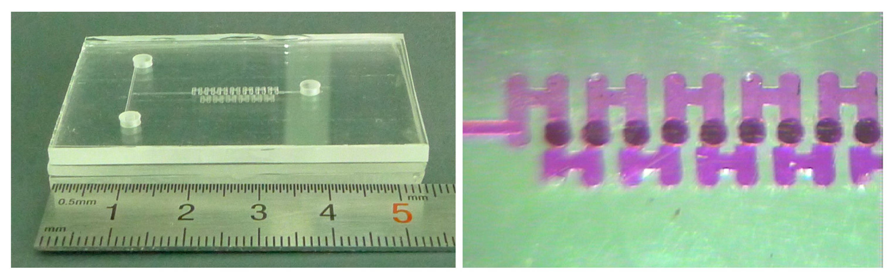
The simple hot-press can achieve the device seal, while the bond strength is 39 N/cm2 and the deformation is 37.8% [13]. The strength and deformation both cannot satisfy complex applications. Oxygen plasma treatment before hot-press enhanced the bond strength to 175 N/cm2 while the deformation reduced to 25%–35% [18]. Solvent assisted also can improve hot-press performance and the process is much simpler and economical. Brown et al. increased the hot-press bonding strength to 550 ± 30 N/cm2 by utilizing the dimethyl sulfoxide (DMSO) miscible solution [28]. In further research of Umbrecht et al., the bonding strength was increased to 780 ± 100 N/cm2 and the deformation was 9.2 ± 2.3% [31]. Organic solvent can seal the device independently, while the bonding strength declines. Tran and his co-workers used 60% ethanol as adhesives, bonding strength was 146.75 ± 1.95 N/cm2 under UV irradiation [32]. In the study of Lin [30], bonding strength of DE-20 solvent was 380 ± 31 N/cm2, about twice of plasma assisted hot-press.
In this work, bond strength is 210 N/cm2 at 30 °C, higher than Tranʼs work, while the deformation is only 4.12%. The bond strength rose to 267.5 N/cm2 at 40 °C and the deformation is 7.26%. Although the bond strength is lower than the values of Lin, but several advantages make the method competitive. First, due to PMMA is slightly soluble in miscible organic solvent, the microchannel blocking does not occur even if the substrates were immersed in the solution. Second, the soaking process not only can provide even coating of adhesives but also eliminate bubbles between bond interfaces, guarantee the bond yield of complex microstructures chip assembly. In addition, the channel roughness is improved by the soaking. Finally, the assembly of multilayer devices expands the applications of soaking method further.

4. Application

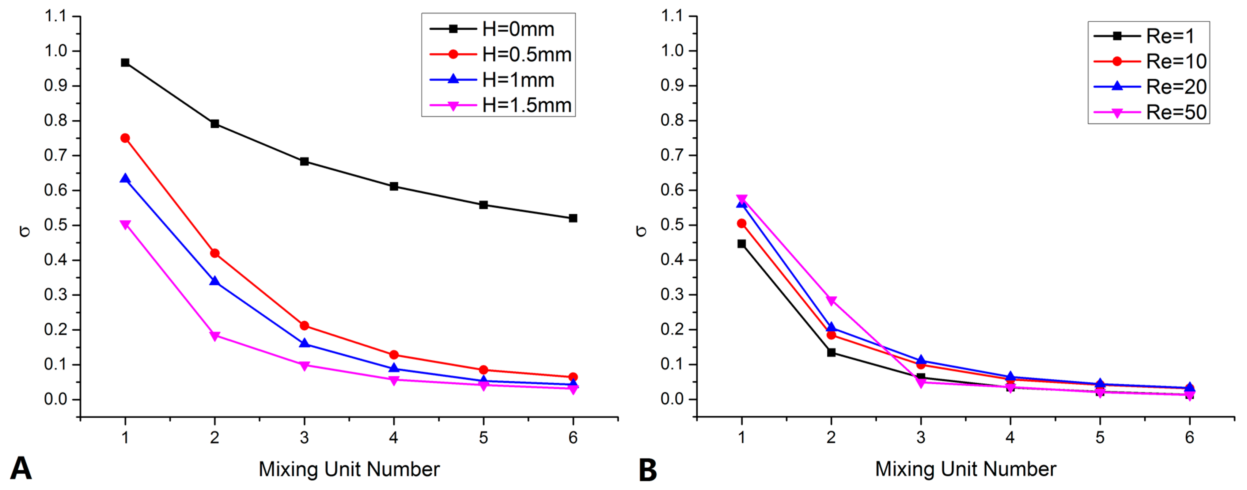
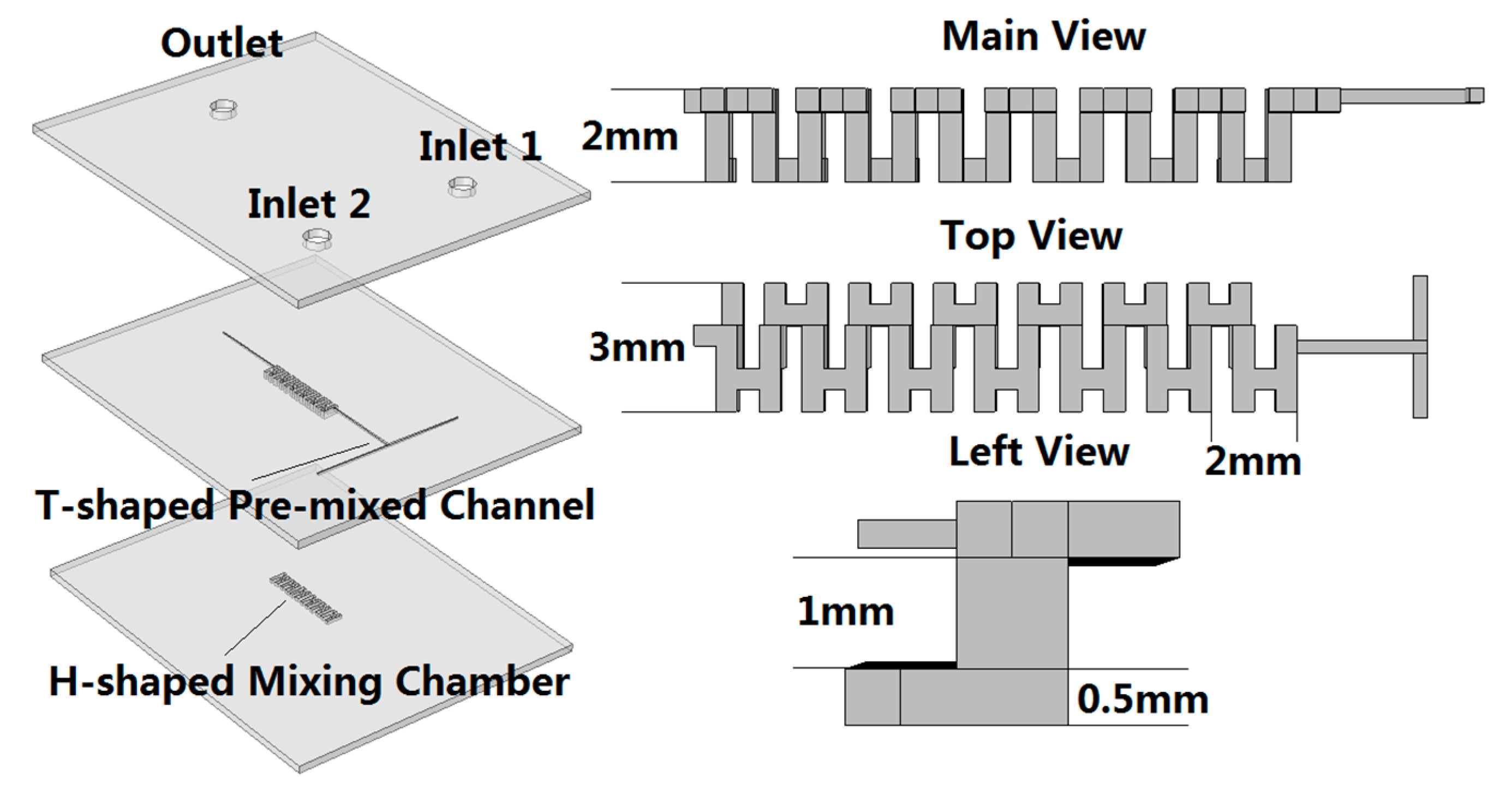
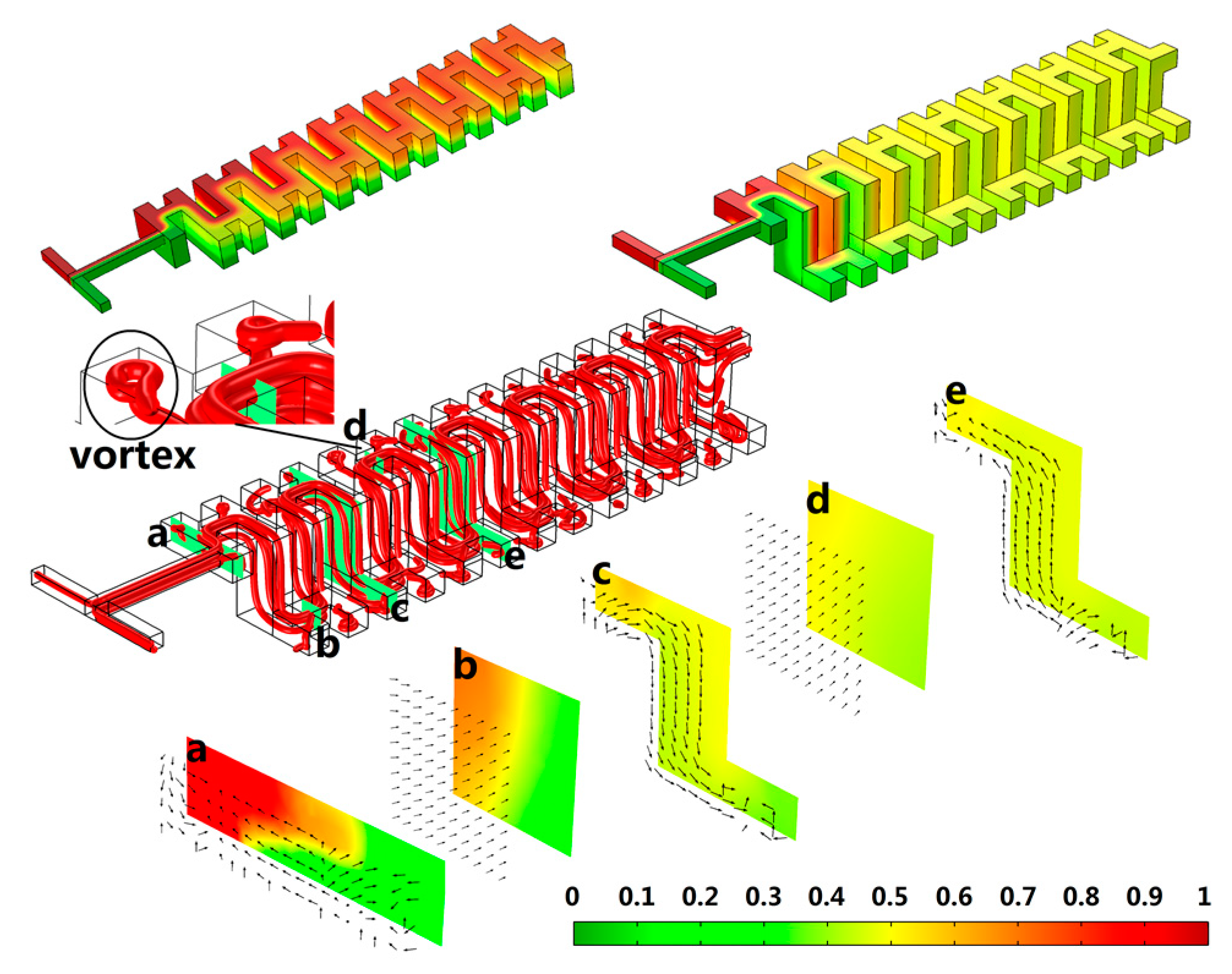
4.1. Mixer Design and Optimize

To evaluate soak bonding performance, a 3D micro mixer was designed, fabricated and tested. The mixer included three PMMA substrates and consists of a T-shaped inlet channel and six H-shaped three-dimensional mixing units. The diagram of micro mixer structure is shown in Figure 8. The substrates have a dimension of 50 mm × 40 mm in lengths and widths, but different thickness. The thickness of the top layer and the bottom layer were 3 mm, while intermediate layer was only 1.5 mm.
Figure 8. The diagram of micromixer structure.
Micromachines 05 01416 g008
A series of simulations were executed to optimize mixer structures. All the simulations were based on the hypothesis of incompressible Newtonian flows and the mass transport equation. When the Reynolds number Re = 10, the concentrations surface, the velocity streamline and the mixing unit slice are shown in Figure 9. The color gradient between 0 and 1 indicated the degree of mixing. In the concentration surface of planar H-shaped mixer, when passed the whole mixing chamber, the fluids was divided into two layers from the top to bottom, but the interface was still clear, the mixing efficiency was not very well. In the 3D mixer, when passed through four mixing units, the surface concentration and chamber slice both showed almost uniform color, the fluids interfaces disappeared. The efficiency improved. As shown in the velocity streamlines, three approaches were utilized to improve the mixing. (1) H-shaped structure. Slight vortices were generated at the end of H structure. (2) Chaotic flows. The chaotic flows arose from the chamber height difference. (3) The increases of diffusion distance. Compared to the planar mixer, the fluids traveled distance increased to 27.1% when the channel height difference was 1 mm.
Figure 9. The concentrations surface and the mixing chamber slice.
Micromachines 05 01416 g009
Mixing concentration variance (σ) was introduced to quantify the mixing efficiency accurately. The concentration variance σ is defined using Equation (3):
σ = 1 N i = 1 N ( C i C ¯ ) 2
where, Ci is concentration of statistical area; N is the number of samples in statistical area; C ¯ is the average of statistics. Five points in each mixing unit outlet were selected as samples. If σ is less than 0.1, samples achieve well mixing. The σ of various chamber altitude difference (H) and different Reynolds Number (Re) were calculated and plotted in Figure 10.
In Figure 10A, the minimum of planar mixer σ was 0.52, far away from the well mixing, while all the three 3D mixer can achieve well mixing. The chaotic flow was the main factor to improve mixing efficiency. Moreover, when H = 0.5 mm, the well mixing length was about 10 mm (passed five mixing units); when H = 1.5 mm, the well mixing length was about 6 mm (passed three mixing units). The increase of diffusion distance still promoted considerable mass transfer. In Figure 10B, when Re ≤ 20, with the increasing of fluid velocity, the σ increased, the mixing efficiency is inversely proportional to fluid velocity. However, if Re = 50, the σ decreased abruptly when passed the third mixing units, and achieved the minimum, the mixing efficiency improved. It is because that, when fluid velocity is extremely slow, mixing is primarily determined by molecules diffusion, relate to time and the fluid contact area. When contact area is constants, the increasing of velocity will reduce the mixing duration. However, with the further increasing of flow velocity, the chaotic flow generated, the mixing efficiency is determined by chaotic flow strength and proportional to fluid velocity.
Figure 10. The mixing concentration variances. (A) The σ of different chamber height when Re = 10. (B) The σ of different Re when H = 1.5 mm.
Micromachines 05 01416 g010

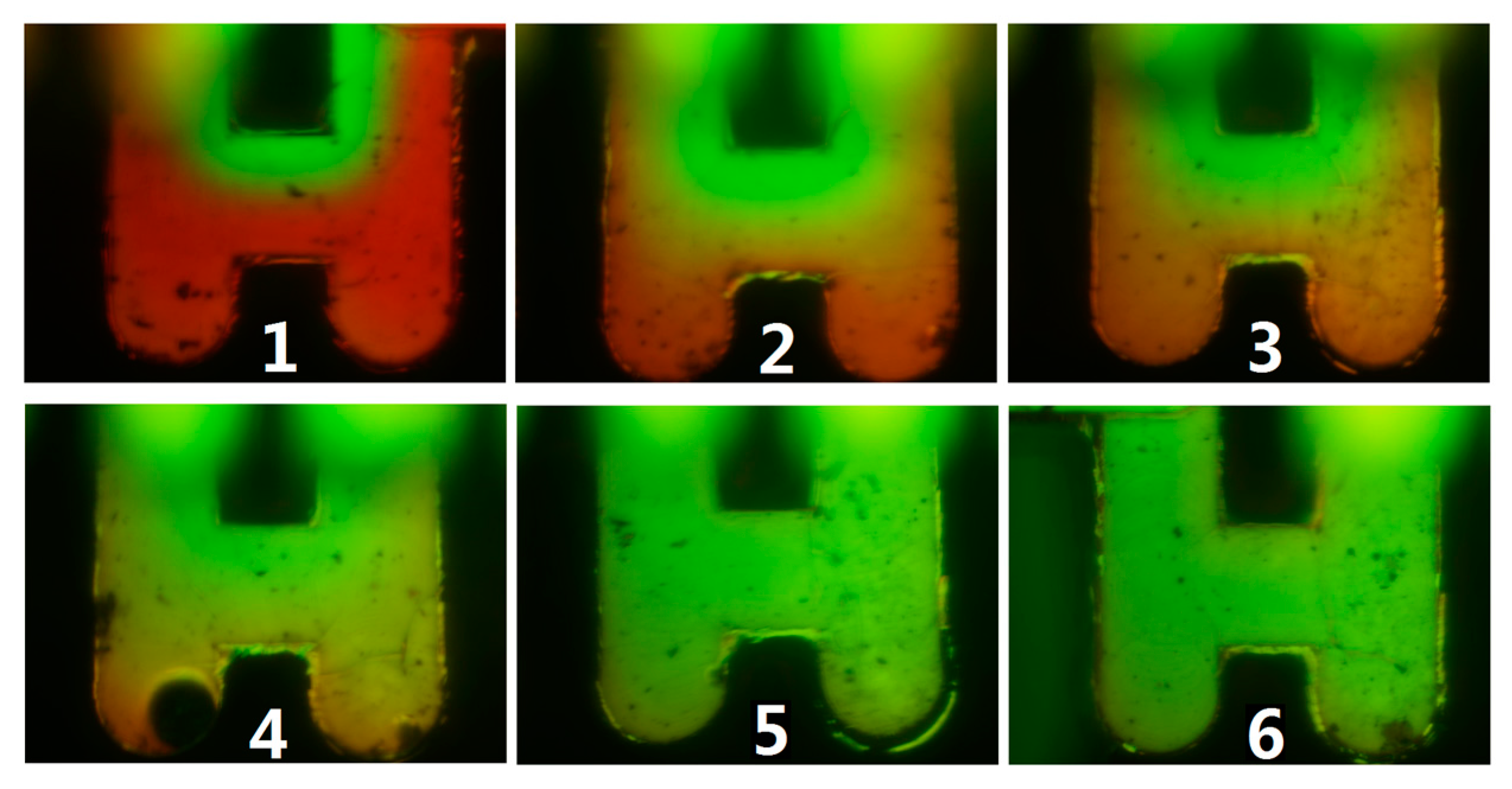
4.2. Mixer Fabrication and Test

The multilayer 3D mixer bonding is similar as the procedure of Section 2.2. First, the cleaned bottom layer and intermediate layer were aligned and fixed. Then, the bonding interface were immersed into miscible solution and heated for 10 min at 40 °C to complete the bonding. The bonded substrate was rinsed by ultrapure water. Replace the used miscible solution and repeat the above procedure to seal top layer. For a multilayer device, only one substrate was bonded in each process. The segmental bonding can ensure the bubbles are completely removed, ensure alignment accuracy and avoid micro structural damage caused by prolonged soak. The photo of mixer and the mixing chamber are shown in the Figure 11.
The fluorescence microscope (IX71, Olympus (China) Co., Ltd., Beijing, China) was used to observe fluid movement in mixing unit; the syringe pump (SN-50F6, Sino Medical-Device Technology Co., Ltd., Shenzhen, China) provided the impetus for the fluids; the fluorescein isothiocyanate (FITC) with concentration of 1 (mol/L) and Rhodamine B with concentration of 1 (mol/L) were utilized as indicators. The fluorescence microscope photos are shown in Figure 12. Since the microscope field depth limited, we can only clearly observe mixing in the intermediate layer. Figure 12 contained four mixing units. In the photo of 1st and 2nd mixing unit, the fluids interface was clear; in the photo of 3rd and 4th mixing unit, the interface was confused; in the photo of 5th and 6th mixing unit, the color approximated consistent. Clearly, the mixing behaviors in 3D mixer agreed well with the simulation results.
Figure 11. The photo of mixer and the mixing chamber.
Micromachines 05 01416 g011
Figure 12. The fluorescence microscopic images of 3D H-shaped mixer.
Micromachines 05 01416 g012

5. Conclusion

In this study, a novel soak bonding method was demonstrated. This method used miscible solution as bonding solvent, and can bond complex structure devices at low temperature and ordinary pressure. A bonding strength of 267.5 N/cm2 can be achieved, while the micro channel deformation was less than 7.26%. Then, an H-shaped multilayer mixer was designed and assembled by using this method. The well mixing length of mixer was only about 6 mm when Re = 10. This fabrication method provides a rapid, cost-effective, and simple way to construct highly functional multilayered microfluidic chips with complex designs. The goal of our method is to assemble μTAS devices based on rigid polymer much more easily.

Acknowledgments

This work is supported by National Natural Science Foundation of China (Grant No.61404036).

Author Contributions

He Zhang designed the experiments and wrote the paper; Prof. Dr. Xiaowei Liu supervised the work and reviewed the manuscript; Prof. Dr. Li Tian contributed reagents, materials and analysis tools; Dr. Xiaowei Han helped interpreting the results.

Conflicts of Interest

The authors declare no conflict of interest.

References

  1. Lin, C.-H.; Wang, Y.-N.; Fu, L.-M. Integrated microfluidic chip for rapid DNA digestion and time-resolved capillary electrophoresis analysis. Biomicrofluidics 2012, 6, 012818. [Google Scholar] [CrossRef]
  2. Amin, A.M.; Thakur, R.; Madren, S.; Chuang, H.S.; Thottethodi, M.; Vijaykumar, T.N.; Jacobson, S.C. Software programmable continuous flow multi-purpose lab on a chip. Microfluid. Nanofluid. 2013, 15, 647–659. [Google Scholar] [CrossRef] [PubMed]
  3. Pang, X.; Lewis, A.C.; Ródenas-García, M. Microfluidic lab-on-a-chip derivatization for gaseous carbonyl analysis. J. Chromatogr. A 2013, 1296, 93–103. [Google Scholar] [CrossRef] [PubMed]
  4. Fang, W.F.; Yang, J.T. A novel microreactor with 3D rotating flow to boost fluid reaction and mixing of viscous fluids. Sens. Actuators B Chem. 2009, 140, 629–642. [Google Scholar] [CrossRef]
  5. Chang, C.M.; Chiou, L.F.; Lin, C.C.; Shieh, D.B.; Lee, G.B. Three-dimensional microfluidic chip for the extraction of mitochondrial DNA. Microfluid. Nanofluid. 2010, 9, 489–498. [Google Scholar] [CrossRef]
  6. Li, J.M.; Liu, C.; Dai, X.D.; Chen, H.H.; Liang, Y.; Sun, H.L.; Tian, H.; Ding, X.P. PMMA microfluidic devices with three-dimensional features for blood cell filtration. J. Micromech. Microeng. 2008, 18, 095021. [Google Scholar] [CrossRef]
  7. Land, K.J.; Mbanjwa, M.B.; Govindasamy, K.; Korvink, J.G. Low cost fabrication and assembly process for re-usable 3D polydimethylsiloxane (PDMS) microfluidic networks. Biomicrofluidics 2011, 5, 036502. [Google Scholar] [CrossRef]
  8. Farshchian, B.; Park, S.; Choi, J.; Amirsadeghi, A.; Lee, J.; Park, S. 3D nanomolding for lab-on-a-chip applications. Lab Chip 2012, 12, 4764–4771. [Google Scholar] [CrossRef] [PubMed]
  9. Chen, R.; Guo, H.; Shen, Y.; Hu, Y.; Sun, Y. Determination of EOF of PMMA microfluidic chip by indirect laser-induced fluorescence detection. Sens. Actuators B Chem. 2006, 114, 1100–1107. [Google Scholar]
  10. Hong, T.F.; Ju, W.J.; Wu, M.C.; Tai, C.H.; Tsai, C.H.; Fu, L.M. Rapid prototyping of PMMA microfluidic chips utilizing a CO2 laser. Microfluid. Nanofluid. 2010, 9, 1125–1133. [Google Scholar] [CrossRef]
  11. Tsao, C.W.; DeVoe, D.L. Bonding of thermoplastic polymer microfluidics. Microfluid. Nanofluid. 2009, 6, 1–16. [Google Scholar] [CrossRef]
  12. Liu, J.; Wang, L.; Liu, C.; Luo, Y. Hot embossing methods for plastic microchannel fabrication. Chin. J. Mechan. Eng. Engl. Ed. 2006, 19, 223–225. [Google Scholar] [CrossRef]
  13. Zhang, H.F.; Liu, X.W.; Peng, Z.C.; Wang, W.; Chen, Y.F. Investigation of Thermal Bonding on PMMA Capillary Electrophoresis Chip. Adv. Mater. Res. 2009, 60, 288–292. [Google Scholar] [CrossRef]
  14. Soper, S.A.; Hashimoto, M.; Situma, C.; Murphy, M.C.; McCarley, R.L.; Cheng, Y.W.; Barany, F. Fabrication of DNA microarrays onto polymer substrates using UV modification protocols with integration into microfluidic platforms for the sensing of low-abundant DNA point mutations. Methods 2005, 37, 103–113. [Google Scholar] [CrossRef] [PubMed]
  15. Tsao, C.W.; Hromada, L.; Liu, J.; Kumar, P.; DeVoe, D.L. Low temperature bonding of PMMA and COC microfluidic substrates using UV/ozone surface treatment. Lab Chip 2007, 7, 499–505. [Google Scholar] [CrossRef] [PubMed]
  16. Mair, D.A.; Rolandi, M.; Snauko, M.; Noroski, R.; Svec, F.; Fréchet, J.M. Room-temperature bonding for plastic high-pressure microfluidic chips. Anal. Chem. 2007, 79, 5097–5102. [Google Scholar] [CrossRef] [PubMed]
  17. Toh, A.G.G.; Ng, S.H.; Wang, Z. Fabrication and testing of embedded microvalves within PMMA microfluidic devices. Microsyst. Technol. 2009, 15, 1335–1342. [Google Scholar] [CrossRef]
  18. Liu, J.; Qiao, H.; Liu, C.; Xu, Z.; Li, Y.; Wang, L. Plasma assisted thermal bonding for PMMA microfluidic chips with integrated metal microelectrodes. Sens. Actuators B Chem. 2009, 141, 646–651. [Google Scholar] [CrossRef]
  19. Li, J.M.; Liu, C.; Liu, J.S.; Xu, Z.; Wang, L.D. Multi-layer PMMA microfluidic chips with channel networks for liquid sample operation. J. Mater. Process. Technol. 2009, 209, 5487–5493. [Google Scholar] [CrossRef]
  20. Gong, X.; Yi, X.; Xiao, K.; Li, S.; Kodzius, R.; Qin, J.; Wen, W. Wax-bonding 3D microfluidic chips. Lab Chip 2010, 10, 2622–2627. [Google Scholar] [CrossRef] [PubMed]
  21. Li, J.; Liu, C.; Ke, X.; Xu, Z.; Li, M.; Duan, Y.; Fan, Y.; Wang, L. Fabrication of a thermoplastic multilayer microfluidic chip. J. Mater. Process. Technol. 2012, 212, 2315–2320. [Google Scholar] [CrossRef]
  22. Lei, K.F.; Ahsan, S.; Budraa, N.; Li, W.J.; Mai, J.D. Microwave bonding of polymer-based substrates for potential encapsulated micro/nanofluidic device fabrication. Sens. Actuators A Phys. 2004, 114, 340–346. [Google Scholar] [CrossRef]
  23. Yussuf, A.A.; Sbarski, I.; Hayes, J.P.; Solomon, M.; Tran, N. Microwave welding of polymeric-microfluidic devices. J. Micromech. Microeng. 2005, 15, 1692–1699. [Google Scholar] [CrossRef]
  24. Rahbar, M.; Chhina, S.; Sameoto, D.; Parameswaran, M. Microwave-induced, thermally assisted solvent bonding for low-cost PMMA microfluidic devices. J. Micromech. Microeng. 2010, 20, 015026. [Google Scholar] [CrossRef]
  25. Ng, S.H.; Wang, Z.F.; de Rooij, N.F. Microfluidic connectors by ultrasonic welding. Microelectron. Eng. 2009, 86, 1354–1357. [Google Scholar] [CrossRef]
  26. Zhang, Z.; Wang, X.; Luo, Y.; He, S.; Wang, L. Thermal assisted ultrasonic bonding method for poly(methyl methacrylate) (PMMA) microfluidic devices. Talanta 2010, 81, 1331–1338. [Google Scholar] [CrossRef] [PubMed]
  27. Luo, Y.; Zhang, Z.; Wang, X.; Zheng, Y. Ultrasonic bonding for thermoplastic microfluidic devices without energy director. Microelectron. Eng. 2010, 87, 2429–2436. [Google Scholar] [CrossRef]
  28. Brown, L.; Koerner, T.; Horton, J.H.; Oleschuk, R.D. Fabrication and characterization of poly (methylmethacrylate) microfluidic devices bonded using surface modifications and solvents. Lab Chip 2006, 6, 66–73. [Google Scholar] [CrossRef]
  29. Hsu, Y.C.; Chen, T.Y. Applying Taguchi methods for solvent-assisted PMMA bonding technique for static and dynamic μ-TAS devices. Biomed. Microdevices 2007, 9, 513–522. [Google Scholar] [PubMed]
  30. Lin, C.H.; Chao, C.H.; Lan, C.W. Low azeotropic solvent for bonding of PMMA microfluidic devices. Sens. Actuators B Chem. 2007, 121, 698–705. [Google Scholar] [CrossRef]
  31. Umbrecht, F.; Müller, D.; Gattiker, F.; Boutry, C.M.; Neuenschwander, J.; Sennhauser, U.; Hierold, C. Solvent assisted bonding of polymethylmethacrylate: Characterization using the response surface methodology. Sens. Actuators A Phys. 2009, 156, 121–128. [Google Scholar] [CrossRef]
  32. Tran, H.H.; Wu, W.; Lee, N.Y. Ethanol and UV-assisted instantaneous bonding of PMMA assemblies and tuning in bonding reversibility. Sens. Actuators B Chem. 2013, 181, 955–962. [Google Scholar] [CrossRef]
  33. De Marco, C.; Eaton, S.M.; Martinez-Vazquez, R.; Rampini, S.; Cerullo, G.; Levi, M.; Turri, S.; Osellame, R. Solvent vapor treatment controls surface wettability in PMMA femtosecond-laser-ablated microchannels. Microfluid. Nanofluid. 2013, 14, 171–176. [Google Scholar] [CrossRef]

