2. “Plasma Pipe” Formation at Pulsed Laser Ablation in Air
Laser-induced air breakdown upon laser-solid interaction in open atmosphere at nano- and microsecond irradiation regimes is a well-established phenomenon [
8,
9,
10,
11,
12], which can be triggered by many factors, in particular due to air humidity [
12]. If air plasma is ignited before the laser pulse terminates, its free electrons start to efficiently absorb incoming laser light via the inverse bremsstrahlung mechanism of absorption. Getting enough energy to overcome ionization barrier (ionization potential) of neutral gas species, they produce secondary electrons in collisions with atoms and molecules, which, in their tern, absorb radiation and produce further electrons. This process is developed exponentially and called
avalanche, which is the reason of air
breakdown. As a result, the laser absorption wave is generated, which can be classified (with increasing laser irradiance) as laser-supported combustion wave (LSCW), laser-supported detonation wave (LSDW), or laser-supported radiation wave (LSRW) [
11]. These waves differ by plasma pressure, temperature, and propagation velocity in the direction to the laser, toward cool atmosphere. However, their common role is in considerable attenuation of the laser beam on its way to the solid surface.
Here we underline another role of laser-induced air ionization, formation of a low-density channel due to lateral gas expansion from the breakdown zone [
13,
14]. This rarefied quasi-cylindrical zone termed the “plasma pipe” [
14] guides the ablation products off from the ablated surface. Its formation is illustrated in
Figure 1. Images (a) and (b) were obtained upon CO
2 laser ablation of polyimide. The laser pulse (10.6 μm wavelength) consisted of a short peak (full width at half maximum (FWHM) of 50 ns) and a tail of ~4 μs in duration. Quasi-spherical expansion of laser plasma was observed at low air pressures (
Figure 1a). A bright spot is seen near the focal point and large luminous fragments of the target material move away from this point. Under the normal pressure conditions, the picture is completely different (
Figure 1b). A narrow directional stream of the luminous plasma/flame propagates from the target toward the laser. Measured emission spectra of the plasma in air consist of the lines of molecules (H
2O, NO, CO, CO
2, N
2), ions (CO
+, N
+, C
+), and molecular fragments (CN, OH), which indicate the combustion of ablation products, most probably initiated by hot breakdown plasma. The consequence of “plasma pipe” formation is that the ablation products, when expending directionally toward the incoming laser light, screen the target additionally to the laser-supported combustion/detonation/radiation waves.
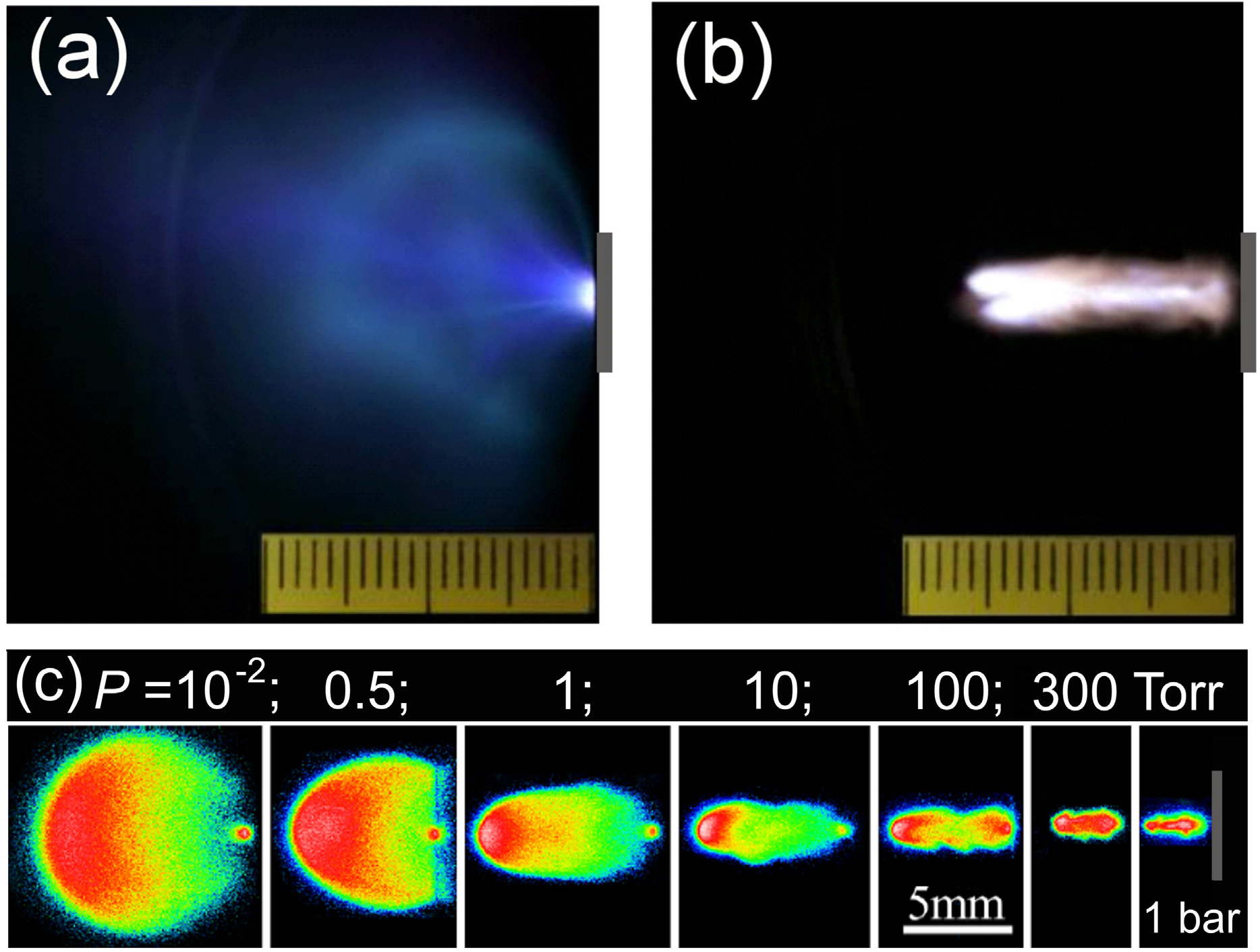
Figure 1.
Spectrally and temporally integrated images of plasma formed upon CO
2-laser ablation of polyimide in air at (
a) 10
−2 Torr and (
b) 760 Torr [
14]. Laser pulse comes from the left. Target location is marked by grey bars. Scale division is 1 mm. Laser fluence
F0 = 50 J/cm
2, total pulse duration ~4 μs. (
c) Spectrally integrated images of ultrafast laser ablation of copper in air at different pressures at 1.2 μs after irradiation (adapted from [
15]). Irradiation conditions for (
c): laser wavelength 800 nm; pulse duration 40 fs; loose focusing (
f = 40 cm); spot size 300 μm; pulse energy 4.5 mJ that would correspond 3.5 × 10
14 W/cm
2 upon irradiation in vacuum. Formation of a “plasma pipe” is clearly seen with increasing the air pressure.
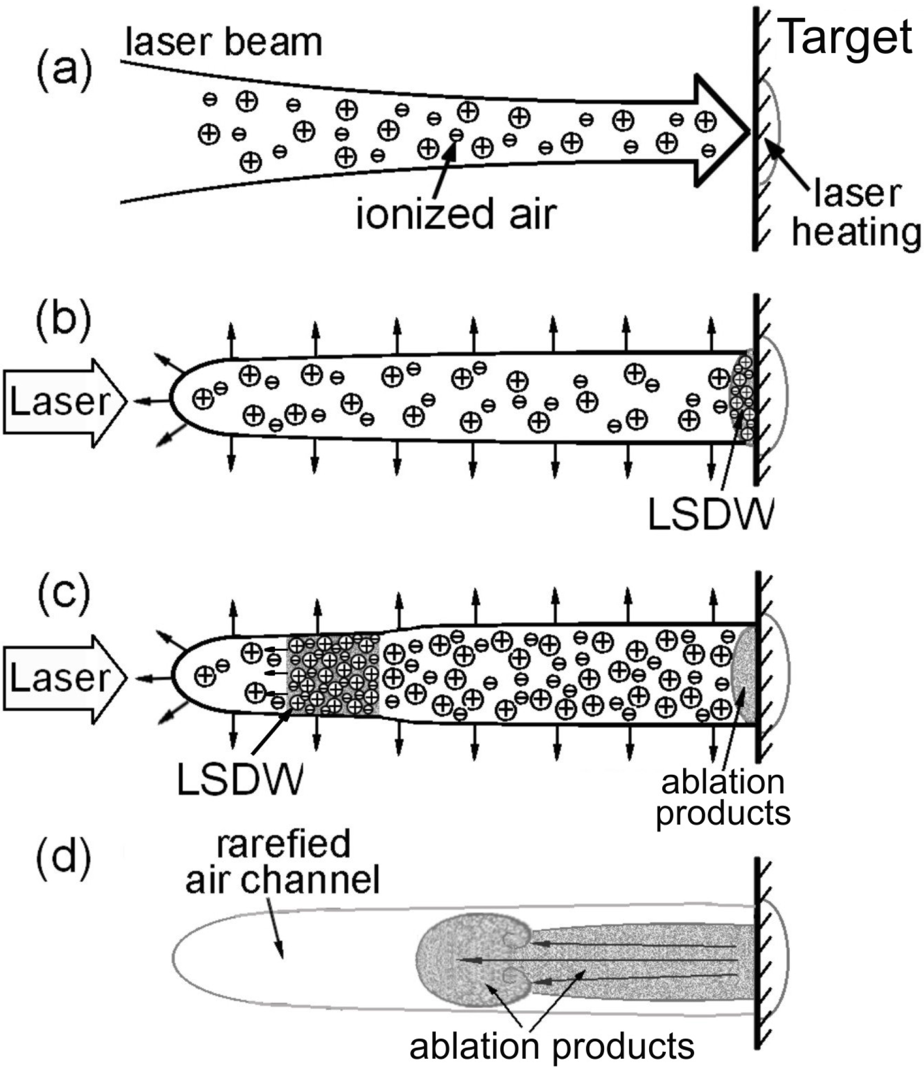
Schematically the process of the plasma pipe development is presented in
Figure 2. When the laser beam of relatively high laser intensity is focused on the target surface, air ionization occurs at the beam axis (
Figure 2a). In our experiments on polyimide and poly(methyl methacrylate) (PMMA) [
14], the ionized air channel in front of the target was detected to be ~5 mm long. Due to the heat release in the ionization zone, ionized air radially expands while the initiated ablation process generates a shock wave with the adjoint LSDW (
Figure 2b). The LSDW propagates along the ionized channel with an estimated characteristic velocity of 5–10 km/s [
14]. A strong heat release in the LSDW leads to the temperature rise up to several eV along the LSDW path and to further reduction of the density of expanding air within the plasma pipe, up to ten times smaller than the initial level [
16]. The ablation products rush to fill this low-density pipe-like region (
Figure 1b and
Figure 2c,d).
Important is that the plasma pipe formation is of a general phenomenon that can be observed for different pulse durations. Furthermore, this effect can be observed even at ultrashort irradiation regimes as shown in
Figure 1c (adapted from [
15]). In experiments [
15], 40-fs laser beams with 4.5 mJ energy were loosely focused on copper targets (
f = 40 cm). In vacuum and low-density ambient gas, irradiance on the target was ~3.5 × 10
14 W/cm
2. Under such low-pressure conditions, the ablation products expand freely, forming a quasi-spherical luminous plasma ball (frame for
P = 10
−2 Torr). With increasing air pressure, the plume becomes directional and, starting already from 10 Torr, it is similar to the polyimide plume in air produced by μs-duration laser pulses (
Figure 1b). This similarity is not occasional. In both cases, air ionization occurs along the beam path to the target that is followed by the formation of
rarefied gas channel “plasma pipe” for the ablation products. However, the mechanisms of air ionization are different. In contrast to ns and longer pulses where the
avalanche (collisional) ionization governs development of plasma in both ablation plumes and air [
8,
9,
10,
11,
12], femtosecond laser pulses
cannot induce gas breakdown even at relatively high ambient pressures. Indeed under normal atmospheric conditions, cross sections for collisions with atmospheric molecules for the electrons with the energy of few eV (velocity of
ve ~ 10
8 cm/s) are ≤10
−15 cm
2 and, hence, characteristic time between collisions is larger than 1 ps. As a result, one can disregard the development of the collisional multiplication of electrons in ambient gas during fs laser pulse and consider photoionization as the main mechanism of air plasma production.
Figure 2.
Schematics of plasma pipe formation and development under conditions of CO
2 laser ablation in air [
14]. See explanation in text.
Figure 2.
Schematics of plasma pipe formation and development under conditions of CO
2 laser ablation in air [
14]. See explanation in text.
To gain insight into dynamics of air ionization by fs laser pulses under the conditions of works [
17,
18], we have developed a simple geometric approach [
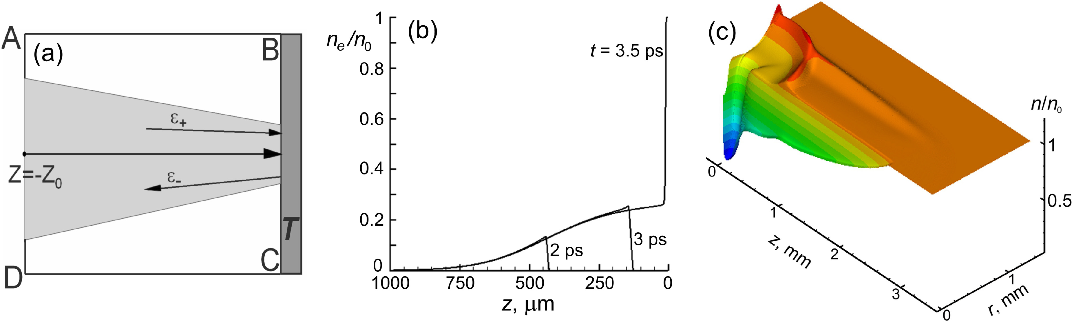
19], which however takes into account laser beam reflection from the target and overlapping of the reflected and incoming beams. Schematics of the modeling geometry is shown in
Figure 3a. The laser beam is assumed to enter from the left into the computational region ABCD filled by an ambient gas (unperturbed argon at 1.08 atm and 20 °C for the case of [
17,
18]) above the platinum target
T. The target is located at
z = 0 (plane BC). Laser beam focusing is described by geometrical optics for Gaussian laser beams. Let the trajectory of a beam ray crosses the target surface in a point with radius ρ from the irradiation spot center so that the trajectory radius
r =
r*(ρ,
z) can be expressed as
r* = (
s(
z)/
s0)
0.5ρ. Here
s(
z) = 1 + (
z –
zt)
2/
zR2;
zt is the distance between the target and the laser focus;
zR is the Rayleigh length;
s0 =
s(
z = 0). At the boundary AD, the incoming laser light flux ε
+ is expressed as follows:
here,
tL = τ/(2
) with laser pulse duration (FWHM) τ = 65 fs;
t0 defines the moment of starting the simulations when the laser beam is entering into the calculation volume ABCD;
c2 =
cz2 +
cr2 is the velocity of light;
cz =
c/[1 + (∂
r*/∂
z)
2]. Then, the following equation can be written for the forward propagation of the beam:
where
Q is the term describing the laser energy losses in a unit volume. As soon as the laser beam reaches the target, the reflected laser flux ε
− is formed with the condition ε
− =
Rε
+ at
z = 0. For simplicity, we assume that the incoming and reflected beam rays propagate along the same trajectory. The difference in trajectories on the air ionization dynamics can give some effect on the results, which, however, cannot be considerable. As shown below, main ionization takes place in the immediate proximity of the surface where the incoming and reflected beams overlap (of the order of 10 μm for τ < 100 fs) while after this zone the reflected beam is attenuated and contributes only little to ionization dynamics. Taking into account that the laser light is absorbed by the ambient gas only via photo-ionization and involving the beam trajectory formalism presented above, we may write:
For simplicity we consider multi-photon ionization
QA =
AJk (
n0 –
ne)/
n0 where
J =
J(
z,
t) =
c(ε
+ + ε
−) is the local laser intensity,
k is the order of photoionization, and
n0 is the initial density of the ambient gas molecules, which is considered unchanged during fs laser irradiation. At high laser intensities the tunneling ionization mechanism can dominate [
20]. As will be shown in
Section 3, the laser intensity clamping effect ensures the Keldysh parameter
> 1 [
20] for air under atmospheric conditions at the laser wavelength of 800 nm.
The evolution of the electron density
ne is described as:
with implying local quasi-neutrality (
ni =
ne). Here the terms
QB,
QC, and
QD describe impact ionization, three-body and photo-recombination processes, respectively [
21,
22]. The energy balance equations describe the dynamics of electron and molecule temperature (
Te and
Ti) relaxation with assumption that ionized and neutral molecules/atoms have the same energy:
where
M is the mass of ambient air molecules; γ is the isentropic exponent;
IAr = 15.8 eV is ionization potential of argon atoms;
E* is the energy released into gas heating via three-body recombination [
21,
22,
23]. The further details of the model and model parameters can be found in [
19,
22].
In
Figure 3b, the simulations results are presented for a 65-fs laser pulse with fluence of 3 J/cm2 irradiating a Pt target, which is located before the laser focus (we assume
zc = 1 mm, and
zt = 0.8 mm). The multi-photon ionization rate for argon was taken based on the data available for Nd
3+-laser (
A = 10
−123 cm
2k/W
k,
k = 10.3) [
24]. The reduced number of
k compared to the value
is explained by two-step ionization via the Rydberg states [
25]. At 800 nm, the photoionization cross section should be larger and, hence, the present simulations give underestimated ionization degree for argon. However, as seen from
Figure 3b, ionization is strong. In contrast to long laser pulses at which the absorption wave (LSCW, LSDW, or LSRW) propagates toward the laser beam [
8,
9,
10,
11], femtosecond-laser-induced ionization front moves together with the laser beam. With approaching the laser wave packet to the target, the ionization wave strengthens (compare curves for 2 and 3 ps) and the ionization degree exceeds 20% already at 300 μm before the target surface.
Figure 3.
(
a) Schematic representation of the computational region for the problem of laser beam propagation and reflection from a metallic target. (
b) The evolution of the ionization degree in argon at the initial pressure of 1.08 bar and temperature of 20 °C during propagation of a 65-fs laser pulse with peak fluence of 3 J/cm
2 at 800 nm wavelength (experimental conditions as in [
17,
18], loose focusing with
f = 20 cm). (
c) Calculated density distribution of argon for the conditions of (
b). A complicated wave structure is seen with a quasi-cylindrical compressive wave propagating radially outward the laser beam axis (
r = 0) and a stronger half-spherical wave moving away from the irradiation spot on the target. At
r = 0 where the hot ambient gas expands radially, a rarefied region is formed (“plasma pipe”). The ablation products have more freedom to move along this “pipe” due to decreased collisional resistance.
At 3.5 ps, the laser beam reflects from the target surface, and beam self-interference results in 100% ionization in a layer of ~20 μm in immediate proximity of the target. The absorbed laser energy accumulated as the potential energy of ionization is released to the gas heating upon recombination whose characteristic time is few nanoseconds [
26]. From Equations (6) and (7), the spatial distributions of the temperatures of electrons and ion/neutral molecules are obtained, which are used as the input data for the model, which describes hydrodynamics of laser-excited ambient gas and its interaction with the target surface, including energy exchange between the gas and the target. The detailed description of the hydrodynamic model is given in [
27]. Application of the hydrodynamic model reveals a complicated shock wave structure combining a quasi-cylindrical compressive wave propagating radially outward the laser beam axis and a half-spherical wave moving away from the irradiation spot on the target (
Figure 3c). Such structures can be recognized in a number of experiments on visualization of laser ablation plume dynamics [
28,
29].
The effect of plasma pipe formation explains well the observed plume narrowing with increasing ambient gas pressure. It should be noticed that plasma plume narrowing (focusing) was first found in [
30] in laser deposition experiments for ns laser pulses. Later it was explained by the analogy with the dynamics of underexpanded jets that assumes transverse oscillations of the plume with distance from the target [
31]. As shown in [
32], the effect connected with the transverse oscillations of the ablation plumes upon its focusing in the presence of an ambient gas can also be observed at fs laser ablation regimes that calls for further studies. Such oscillations are a natural feature of plume expansion dynamics, which can be superimposed with the plasma pipe effect and most probably are damped with increasing ambient pressure.
3. Other Effects of Air Ionization at Femtosecond Laser Processing
In the previous section it has been shown how dramatically air ionization at ultrashort laser processing can change the expansion dynamics of laser ablation plumes, resulting in strong plume focusing. Here we concentrate on the role of laser light absorption by air for the ablation process and its interpretation for the case of femtosecond laser pulses as the most of laser micromachining technologies and scientific experiments on ultrashort laser ablation take place in open air. It should be underlined once more that air ionization mechanisms are different for femtosecond pulses and longer ones. As mentioned above, at femtosecond laser pulses free electrons generated by photoionization of ambient gas molecules have no time to collide with other air species during the laser pulse. As a result, bremsstrahlung absorption and associated avalanche ionization are not developed and, hence, no breakdown of ambient atmosphere is developed. However, ionization degree of an ambient gas can be very high as shown in
Figure 3b for the case of argon. Free electrons produced solely by photoionization stay cold. Under such experimental conditions no plasma spark is usually observed that often is attributed to the absence of laser light absorption in air. Placing the target before the laser focus to avoid air ionization does not help to avoid air ionization in front of the target. As soon as a definite laser beam intensity
J(
r,
z) has been reached upon focusing at a distance
zcr before the target, the swift air ionization is developed due to a power dependence of multi-photon ionization rate
AJk. After passing this critical point
zcr, the beam ionizes air molecules (or other ambient gas) on its way to the target. The
zcr value and the ionized volume geometry in radial direction depend on the numerical aperture of the focusing lens and the spatial form of the laser beam (Gaussian, Bessel, top-hat, annular [
33]). At relatively low beam energies, noticeable air ionization can develop only at the region of interfering the incident and reflected parts of the beam. But for fs laser energies used for material processing, air ionization is unavoidable under normal atmospheric conditions that leads to manifestation of a strong intensity clamping effect [
34]. The part of laser energy lost for air ionization drops with decreasing ambient gas pressure but can be considerable even at such low pressures as 10 Torr as is evident from
Figure 1c [
15].
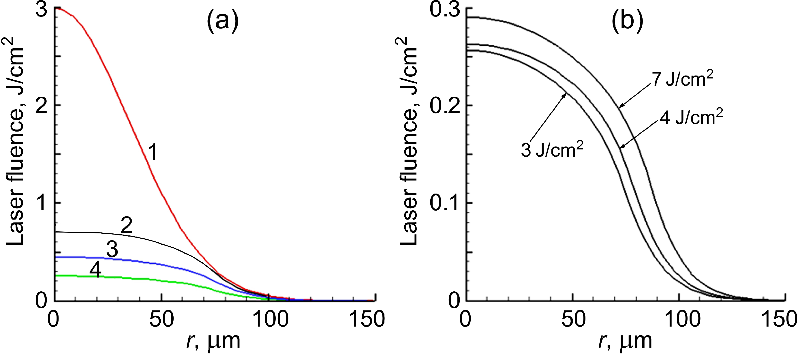
Figure 4 demonstrates the energy clamping effect for the experimental conditions in argon [
17,
18]. According to simulations, less than 25% of energy of the laser pulse with 65 fs duration whose fluence would be 3 J/cm
2 in vacuum reaches the target surface (
Figure 4a, black solid line 2) while the rest is spent for air ionization. At later stages, a part of energy can couple to the target during and after plasma recombination process due to convective and radiating energy exchange between the ambient and solid target [
18,
27]. This can result in the enhanced residual heat effect discovered by Vorobyev and Guo [
17], which depends on the ionization potential of ambient gas. However, laser energy absorbed by air and returned to the target after the laser beam action leads to reducing the processing quality [
27,
35,
36].
Figure 4.
(
a) Calculated radial distributions of laser fluence on a platinum target surface located at the beam focus for the experimental conditions reported in [
17,
18]. Laser wavelength is 800 nm; pulse duration is 65 fs; loose focusing (
f = 20 cm). Line 1 shows the laser fluence distribution in vacuum with a peak value of 3 J/cm
2. The other lines show fractions of the laser energy reached the target surface after absorption in air (2), absorbed by the target (3), and reflected (4) for irradiation in air under normal conditions. (
b) Radial distributions of the fraction of laser energy absorbed by the Pt target for three different peak fluences, which clearly demonstrate the intensity clamping effect, due to air ionization in the way of the laser beam to the target surface. Experimental conditions are as in (
a).
The higher the laser beam fluence which could be reached on the surface in vacuum or low-density gas environment, the more laser energy is lost for air ionization (the larger is
zcr and, hence, gas ionization volume).
Figure 4b is a bright demonstration of the energy clamping effect: at three different fluences almost the same laser energy is absorbed by the target
directly from the laser beam. We underline that partially the laser beam energy absorbed by air returns to the target in the form of recombinative and bremsstrahlung radiation as well as via conductive and convective heat exchange between the gas and the solid target. However, the mentioned heat-exchange processes take place in other, longer timescales. Radiative target reheating from the ionized ambient gas occurs during several nanoseconds characteristic for the plasma recombination process while the conductive and convective heat exchange can proceed up to milliseconds as revealed in [
27]. Our simulations show that three-body recombination strongly dominates photo-recombination and, hence, the conductive and convective heat exchange is the main process for target reheating after the laser pulse termination.
Disregarding the effects of air ionization can lead to misinterpretation of the experimental results. As an example, using ultrafast time-resolved shadowgraphy [
37] an intriguing dynamic picture of intense 50-fs-laser ablation of aluminum at 800 nm wavelength was revealed at early ablation stages, which was explained by the authors with the phase explosion concept. However, we found that such an interpretation is hardly consistent with other observations and simple energy considerations. An alternative, more realistic interpretation of the shadowgraphs was proposed [
38], which assumes laser-induced air ionization and explains consistently all features reported in [
37]. Here we present modeling results for the experimental conditions of work [
37], which completely support the analysis made in [
38] (the only issue is in terminology as the term “breakdown” is better to change to “air ionization” in view of the absence of the avalanche process).
The set of Equations (1)–(7) was used to simulate air ionization in front of an aluminum target at focusing with a 10× objective. Air was considered as a mixture of N
2 and O
2 with a concentration ratio C
O2:C
N2 = 0.78:0.22 and with disregarding other air species. The multiphoton ionization term in Equations (3) and (4) was rewritten as
QA =
AO2 Jk1 (
n0C
O2 –
ne) +
AN2 Jk2 (
n0C
N2 –
ne). The multiphoton ionization rate constants for 800 nm radiation were taken from [
39]:
AO2 = 1.67 × 10
−77 cm
13/(W
8 s) (ionization potential
IO2 = 12.1 eV,
k1 = 8) and
AN2 = 1.26 × 10
−122 cm
19/(W
11 s) (
IN2 = 15.6 eV,
k2 = 11) with air density
n0 = 2.7 × 10
19 cm
−3. Equation (7) was correspondingly rewritten to account for the energy balance upon ionization, recombination, and electron-molecule thermalization. Note that in the model we do not take into account dissociation of the molecular constituents of air that can also have some impact on the process dynamics. However, the presented modeling does not lose its significance as it demonstrates a dramatic effect of air ionization as shown below. Taking into account the dissociation reactions would lead to some decrease in the gas temperature in view of energy expenses for dissociation while the gas density would increase, thus balancing gas pressure but not cancelling the air ionization effect.
Numerical modeling was performed for the experimental parameters of [
37]: a laser pulse of 50 fs duration with a fluence on the target surface (considered for vacuum) of 40 J/cm
2. In view of a poorly defined geometry of beam focusing in [
37], it was set as follows. A plan apochromatic lens was considered with numerical aperture (NA) = 0.45. The target was placed well before the geometrical focus to secure the irradiation spot diameter on the Al surface of 25 μm that can be estimated from
Figure 2 of work [
37]. The simulations show that immediately after the laser pulse termination, 100% single ionization is reached in a region adjacent to the irradiation spot, which is ~50 μm thick along
z-direction and ~30 μm in diameter. At 300 μm from the target, the ionization degree drops to ~5% with further gradual decreasing outwards the target. At a rather large NA value as in [
37], the fraction of the laser energy absorbed by air is relatively small, approximately 5% of the initial beam energy. However, as shown in [
38], this fraction can strongly influence the probe signal. Note that for loose focusing conditions the energy fraction absorbed by air can constitute the major part of the total pulse energy (see
Figure 4).
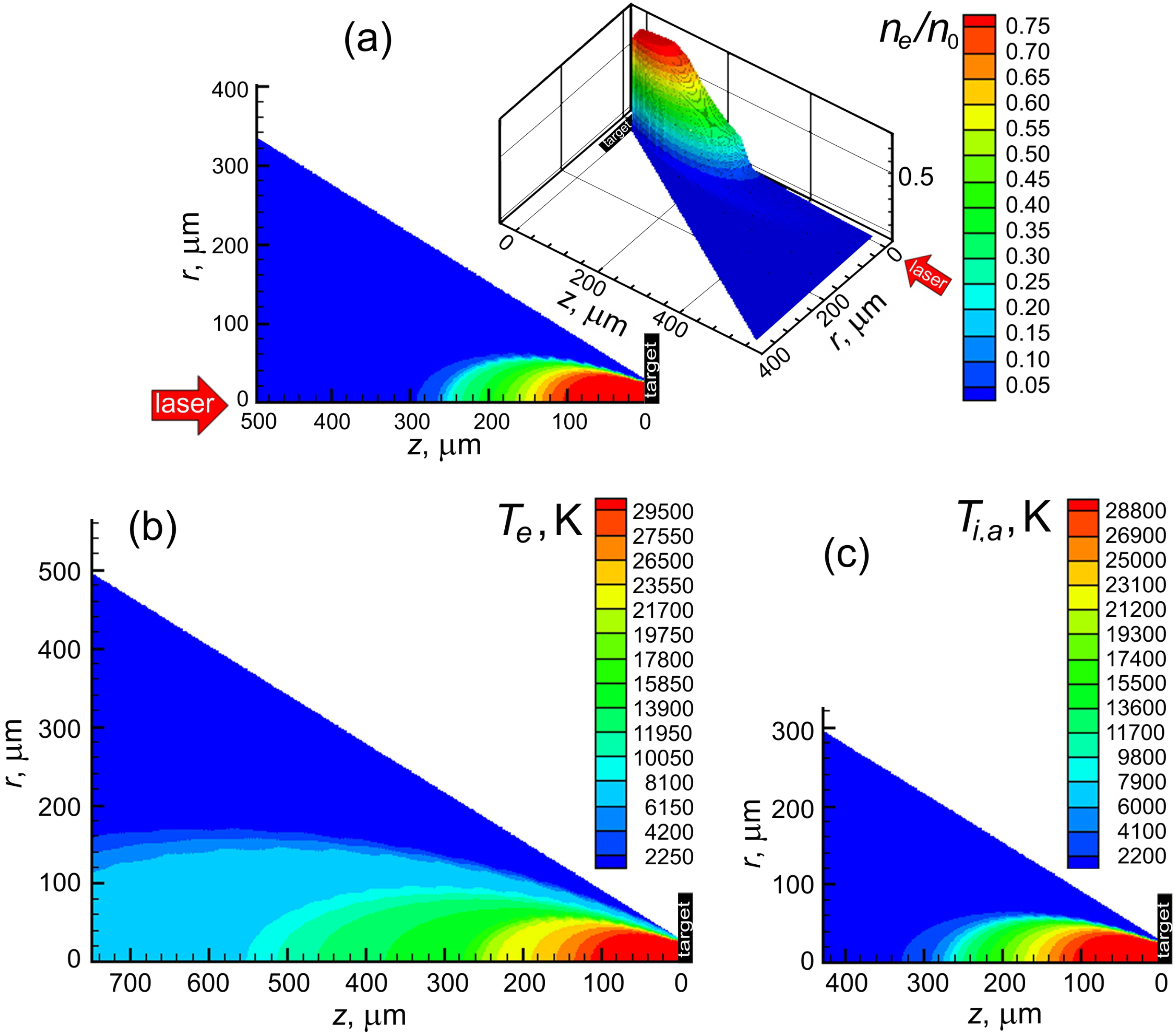
Figure 5 shows the distributions of the electron density and the temperatures of electrons and air molecules in front of the target at a time moment of 1 ns after the laser pulse termination. By this time, the ionization degree in the near-target region decreases by approximately 25% (
Figure 5a) while the ionized gas is already close to local ionization equilibrium in this zone. At
z distances larger than ~150 μm where the ionization degree drops, electrons are still considerably hotter than molecules. As was commented in [
38], such hot dense plasma can strongly scatter the probe laser beam, being thus responsible for the dark region formation at early stages observed in [
37]. Besides, the probe beam can be deflected by involving air in motion, which generates a shock wave. Indeed, the air molecules with a temperature of ~30,000 K travel 2–3 μm during 1 ns that can lead to a noticeable perturbation of the air density, especially in regions of considerable temperature (and, hence, pressure) gradients. Furthermore, it can be expected that air molecule dissociation can result in even stronger perturbation of the probe signal. When decaying in the time scale of several nanoseconds [
26], the plasma becomes transparent. However, due to spatial nonuniformity of the air density in the developed hemispherical shock-wave pattern, a complicated character of the deflection and scattering processes can result in formation of a stripe pattern. Shadowgraphs similar to those observed in [
37] including the stripe pattern were reported for silicon irradiated by 100 fs-laser pulses at 10
14 W/cm
2 [
27] and the observed structure was attributed to the shock wave formation [
7]. At present, air ionization dynamics upon laser material processing still calls for further extensive studies in order to determine ways of reduction of harmful effects of the air plasma on the processing efficiency and quality.
Figure 5.
(
a) Calculated distribution of the ionization degree of air in front of an aluminum target at 1 ns after irradiation for the experimental conditions of work [
37].
r and
z are the radius counted from the laser beam axis and the distance from the target in air, respectively. Laser wavelength is 800 nm; pulse duration is 50 fs; fluence is 40 J/cm
2. For a clearer representation, the distribution is given as a contour map and 3D surface. (
b,
c) present the spatial distributions of the electron and molecule (both neutral and ionized) temperatures for the conditions shown in (
a). Time moment is 1 ns after irradiation.
4. Plasma-Assisted Ultradeep Ablation
In the two previous sections, it has been shown that, at femtosecond regimes of laser material processing in gas surroundings, ionization of an ambient gas can occur that influences the ablation process, hampers its diagnostics, and may lead to considerable attenuation of the laser beam on its way to the target. Furthermore, the laser energy absorbed by air can be coupled to a solid target at timescales up to milliseconds due to radiative, conductive, and convective heat exchange between the laser-perturbed gas and irradiated target. In this section, we analyze the ablation plasma impact on the ablation process. It is well established that, at irradiation regimes with pulse duration of nanoseconds and longer, the laser-produced plume shields the target from the laser beam that results in a saturation of the mass removal in the surface vaporization regimes [
6,
40,
41]. Analysis of the laser energy balance shows that the plasma plume can accumulate more than 40% of the laser beam energy [
42]. Such a hot plasma induces ejection of molten matter due to the plasma recoil pressure. On the other hand, plasma radiation (both recombinative and bremsstrahlung) can lead to additional heating of the target material [
9,
43,
44,
45]. While the role of the recoil pressure of plasma plumes under PLA is extensively discussed in the literature (see, e.g., [
46,
47,
48,
49]), detailed analysis of the plasma reradiation effects on the ablation process is still lacking. Only recently comprehensive experimental and theoretical studies were performed, which have shown that the radiating laser-ablation plasma can dramatically influence the ablation dynamics, leading to the formation of ultradeep craters [
50,
51,
52]. On the example of graphite, it was clearly demonstrated that ultradeep crater formation can only be explained based on the concept of ablation plasma absorption and reradiation [
50,
51]. Graphite, which melts at pressures ≥100 bar and has a relatively small gap between the melting and boiling temperatures at the same pressure, is the brightest example of the plasma feedback effect though the latter has a universal character regarding the type of material [
52]. In this section, we present a short overview of the effect of ablation plasma radiation on the ablation rate and discuss further possible consequences.
Formation of very deep craters upon nanosecond laser ablation is attributed to ablation regimes when the mechanism of normal (surface) vaporization is suddenly changed to the dominance of a violent ejection of a mixture of vapor and liquid droplets from the volume of irradiated target, called usually phase explosion or, more traditional, explosive vaporization. The threshold laser irradiance is typically of the order of 10
9 W/cm
2 for inorganic materials [
40,
42,
53,
54,
55,
56]. Phase explosion is stimulated by a homogeneous nucleation of the vapor phase within a molten layer superheated relative to the surface when the growing vapor bubbles tear the liquid matter into pieces. In the explosive ablation regime, the surface vaporization of particles is developed during the laser pulse action resulting in the formation of a hot light-absorbing plasma in the ablation products [
40,
56]. The subsequent, often dominant by amount, volumetric ejection of the vapor-droplet phase happens after the pulse termination [
46,
55]. Ablative craters produced in the regimes of volumetric material ejection can be very deep reaching, in some cases, several or even tens of micrometers in depth per pulse [
40,
45,
55]. Such ultradeep laser drilling cannot result from a common heat conduction transport into the target bulk and was suggested to be due to ablative laser plasma effects [
45,
50].
To prove the concept put forward in [
45], the experiments were performed supported by numerical modeling [
50]. Ablation of a polycrystalline graphite plate was carried out under vacuum conditions (10
−5 Pa) with a frequency doubled Nd:YAG laser (532-nm wavelength, pulse of a Gaussian temporal profile of 7-ns (FWHM) duration). The laser beam was focused at normal incidence by a glass lens (100-mm focal length) into a circular spot of a diameter in the range 0.1–0.3 mm (1/
e2-level). Laser fluence
F0 on the target surface was varied in the range of 1–50 J/cm
2. The ablation depth measurements were performed translating the target to have identical irradiation conditions during multipulse ablation series. The ablation mass was accumulated over 10
3–10
4 laser shots. The average mass removal per pulse was determined by measuring the target weight before and after irradiation. The craters were examined with an optical microscope (a CCD camera Toshiba IK-M50H (Toshiba Corp., Tokyo, Japan) equipped with a Mitutoyo M-Plan APO 10× objective (Mitutoyo Corp., Kanagawa, Japan) and a Navitar Zoom 4× lens (Navitar, Inc., Rochester, NY, USA).
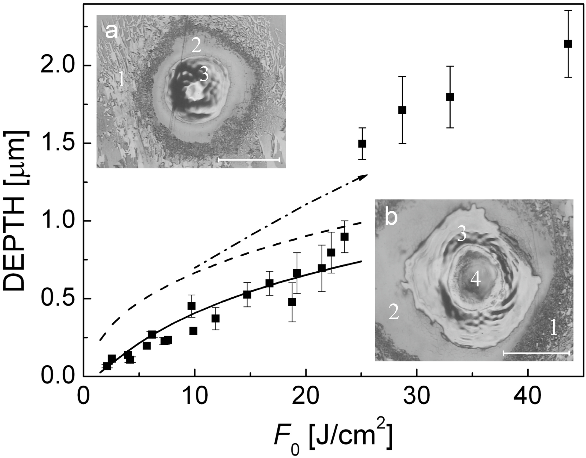
Figure 6 presents the experimental data on the ablation depth as a function of incident laser fluence
F0 (dark squares). The ablation threshold can be determined as
Fabl ≈ 1.5 J/cm
2. The sudden increase in the ablation depth at ~22 J/cm
2 corresponds to the second threshold
Fexp, the transition to explosive vaporization. Images of typical craters produced by 30 laser shots below and above
Fexp are shown in insets. Frozen capillary waves are distinctly seen, unambiguously indicating melting of graphite even at relatively low laser fluences, near the ablation threshold
Fabl. At laser fluences >
Fexp, a distinct area of ultradeep ablation can be recognized in the center of the irradiation spot with a smooth bottom, which is surrounded by a zone of the re-solidified material. The depth in the center reaches 2–3 μm per pulse (note the ablation depth given in
Figure 6 was averaged over the irradiated spot area). The obvious melting of graphite indicates that, during the ablation, the carbon vapor pressure above the target reaches, at least, 100 bar [
57,
58]. Hence, the observed transition to the ultradeep ablation can be attributed to the formation of a thick layer of molten graphite whose explosive vaporization together with the high recoil pressure leads to sharp deepening of the crater.
Figure 6.
Measured ablation depth of a graphite target (averaged over the irradiation spot) as a function of laser fluence (dark squares) [
50]. Modeling results on the ablation depth are shown by solid line. The onset of “ultradeep drilling” (phase explosion) is seen at ~22 J/cm
2 as a sudden increase in the ablation depth. The other lines show the calculated maximum depths of melting (with respect to the initial target surface) obtained with the thermal model taking into account plasma shielding (dashed line) and, additionally, with contribution of plasma radiative heating (dot-dashed line). Details of the calculations are given in [
50]. The insets show optical microscope images of craters formed on the graphite surface by 30 consecutive laser shots at fluences (
a) 3 J/cm
2 and (
b) 24 J/cm
2. The scale bar corresponds to an irradiated spot size (1/
e2 level) for both cases. Several zones can be marked out: (1) non-damaged surface, (2) an external area of the irradiated spot where laser energy is insufficient to induce melting, (3) a zone with clear traces of melting, and (4) a deep area in the middle of the irradiated spot with a smooth bottom where melting traces are hardly distinguished.
![Micromachines 05 01344 g006]()
A
three-stage theoretical model was proposed [
50] aiming at elucidating the dynamics of heating, melting, and ablation of graphite under these experimental conditions in order to get an insight into a possible role of the laser ablation plasma in the ultradeep ablation process. In the
first stage, the thermal model with accounting for the plasma shielding effect was employed [
6,
40,
42,
50]. The model is based on solving a heat flow equation in its one-dimensional form that allows analyzing the evolution of the temperature profiles
T(
t,
z) toward the target depth
z:
Here ρ,
cp, λ, α
b, and
R are the mass density, the heat capacity, the thermal conductivity, and the absorption and reflection coefficients of the irradiated material, respectively. The term
Lmδ(
T –
Tm) allows the calculations across the liquid-solid interface, having the temperature
Tm;
Lm is the latent heat of fusion; δ(
T –
Tm) is δ-function whose computational domain is usually about five computational cells. The vaporization rate
u(
t) is defined under the assumption that the flow of vaporized molecules from the surface follows the Hertz-Knudsen equation and the vapor pressure above the vaporized surface can be estimated using the Clausius-Clapeyron equation [
6,
40]. An important feature of our model is that it takes into account the effect of plasma plume shielding of laser radiation by considering not only the amount of vaporized material but also vapor/plasma heating. This allows modeling the ablation process and the laser energy balance over the fluence range where the normal vaporization mechanism is dominant [
6,
40].
The results of modeling are shown in
Figure 6 by solid (ablation depth) and dashed (melting depth) lines. Surprising is that the measured ablation depth in the regimes of explosive vaporization is well deeper than the maximum thickness of the molten layer obtained in the simulations. Hence, such a deep ablation cannot be explained under the assumption that the whole molten layer is ejected from the target via the phase explosion mechanism. A plausible explanation of this fact is that the conventional thermal model underestimates the melting depth at fairly high laser fluences. The target can be additionally heated by radiation (both bremsstrahlung and recombinative) of the ablation plasma plume [
9,
45] that is not accounted for in the thermal modeling. During thermal modeling, the accurate energy balance can be calculated via determining the laser energy fractions, which are reflected from the target surface (
ER), lost to the target heating (
Et), absorbed by the emerging plasma (
Eab), and used for surface vaporization (
EL is the part corresponding to the latent heat of vaporization and
Eth is the thermal energy of the vaporized particles) [
42,
50]. It has been found that, at fluences near
Fexp, laser-ablation plasma plumes can absorb more than 50% of the incident laser energy. Thus, we can assume that a considerable part of plasma radiation is coupled to the target. Furthermore, hot laser-induced plasmas efficiently emit in the UV spectral range [
43,
44,
45,
59] where the reflection coefficient of materials is smaller as compared to IR and visible ranges. As a result, this additional heating can considerably increase the molten layer thickness.
To evaluate the additional heating of the target due to plasma radiation, the spherical model of laser plume expansion was exploited [
22,
31] as the
second stage of modeling. The model allows to simulate ionization/recombination dynamics of the plasma and its energy balance and, hence, to evaluate the temporal dynamics of plasma radiation. According to the model, we assume that, by the end of laser pulse, the vaporized atoms are distributed uniformly in a half-sphere volume. The initial temperature
Tin of the neutral carbon vapor is estimated on the basis of the energy balance as
Tin =
T0 + 2/3 × (
Eab +
Eth)/(
kBNvap). Here
T0 = 300 K;
Nvap is the number of vaporized carbon atoms;
kB is the Boltzmann constant. Assuming the local ionization equilibrium, the initial plasma temperature and ionization degree are determined with an iterative procedure as described in [
22]. The spherical plasma plume with the pre-determined parameters is allowed to expand freely into vacuum and we follow the evolution of the plume parameters (the electron and ion densities and temperatures, ionization degree) and plasma radiation. For singly ionized plasma (
Z = 1), the photo-recombinative losses can be expressed as [
22]:
In Equation (10),
e is the unit charge, the electron and ion densities (
ne,
ni) are measured in cm
−3, and the electron temperature
Te and ionization potential of carbon atoms
IC are in eV. On the other hand, the radiation power densities of the bremsstrahlung and photo-recombination processes can be estimated as [
59]:
Here the electron temperature is measured in Kelvins. Simulations have shown that Equations (10) and (12) give at
Z = 1 the same recombinative radiation power. The temporal dynamics of plasma radiation was recorded for further introducing at the
third stage of simulations as an additional energy source of the thermal model.
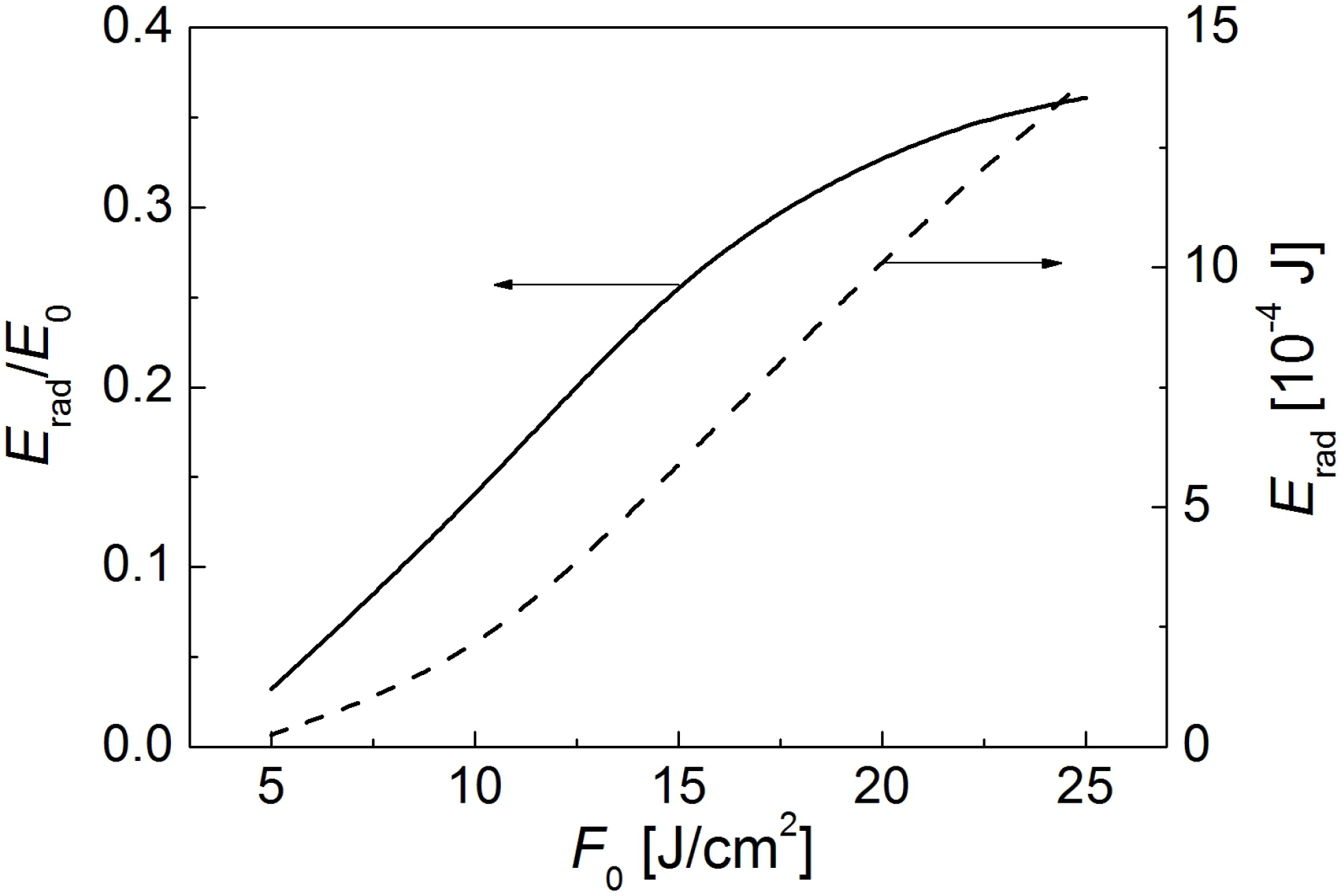
Figure 7 shows the total plasma emission
Erad calculated by integrating the bremsstrahlung (Equation (11)) and photo-recombinative (Equation (10)) power densities over space and time during simulation of the plasma expansion. It is seen that the efficiency of the re-emission of the laser energy absorbed by the plasma increases with increasing laser fluence.
In the third stage, the traditional thermal model was refined by introducing an effective plasma radiation source. To do this, the laser energy source in Equation (8) was changed to the form
with
where
is the sum of the recombinative radiation and bremsstrahlung emission intensities recorded in the
second stage of modeling. Here
Rpl and α
pl are effective values of the reflection and absorption coefficients for graphite at wavelengths of plasma emission. Since the recombinative radiation dominates under the considered ablation conditions [
50], we arbitrarily assume that the plasma radiates at ~950 Å. The corresponding photon energy is ~13 eV that is the ionization potential of carbon atoms plus an average electron energy of ~2 eV at early expansion stages as obtained in the calculations. Thus we use
Rpl = 0.18 and α
pl = 7.7 × 10
5 cm
−1 [
60]. The thermal simulations were repeated with the new energy source term, assuming that the plasma radiation starts at the moment of the incident laser intensity maximum when the plasma plume is already developing. Surprisingly, the ablation depth of normally vaporized graphite is almost insensitive to the introduction of this additional heating term while the depth of the molten layer has notably increased at
F0 > 10 J/cm
2. As a result, at fluences near the
Fexp value, the total depth of ablated and molten material is approaching the experimentally observed ablation depth (
Figure 6, dash-dotted line). Assuming that in the regime of explosive vaporization the whole molten layer becomes superheated and is ejected from the target surface, we obtain a convincing explanation of the ultradeep ablation effect.
Figure 7.
The total energy
Erad radiated by the plasma plume during its expansion into vacuum as a function of laser fluence [
50].
E0 is the incoming pulse energy. The plume is produced by ablation of graphite with Nd:YAG laser pulses (7 ns, 532 nm).
Figure 7.
The total energy
Erad radiated by the plasma plume during its expansion into vacuum as a function of laser fluence [
50].
E0 is the incoming pulse energy. The plume is produced by ablation of graphite with Nd:YAG laser pulses (7 ns, 532 nm).
The explanation of ultradeep drilling was supported recently by comprehensive experimental and theoretical studies performed by Hoffman
et al. [
51] using 355, 532 and 1064 nm wavelengths generated by a nanosecond Nd:YAG laser. It was found that at lowest wavelength, the transition from thermal ablation to phase explosion takes place at lower laser fluences. The results have demonstrated that radiation of laser ablation plasma is of utmost importance for overall ablation process in the regimes of high laser fluences exceeding the threshold for phase explosion emergence. However, laser-induced plasma can affect the laser processing also at moderate laser fluences through inducing surface chemistry as will be discussed in the next section.
5. Role of Plasma Chemistry: “Microtower” Growth upon Ablation of Liquid Metals
Plasma etching of different surfaces is a widely studied phenomenon due to its extensive usage in plasma-chemical technologies [
61]. Even a plasma of inert gases becomes an etching agent when its energetic ions bombard contiguous surfaces. Plasma of highly reactive gases causes strong corrosion of surfaces and is used for selective removal of masks in circuit fabrication. Liquid media, such as water and organics used for laser-assisted nanoparticle production [
62,
63], obtain extreme reactive properties when reach their critical or supercritical thermodynamic states [
64,
65,
66]. In recent years plasma of gas discharges was successfully utilized for fabrication on various nanoobjects on surfaces [
67,
68].
The target surface is subjected to the action of ionized gas, which is not only originated from the ablation process but also induced by ambient gas photo-ionization as demonstrated in
Section 2 and
Section 3. Additionally, formation of laser-induced shock waves implies partial ionization of compressed ambient atmosphere. Laser-processed surfaces in contact with plasma are exposed to bombardment of energetic ions, electrons, and neutral atoms. This can lead to substantial modification of the surface via mechanical sputtering and chemical etching. Upon femtosecond laser ablation of aluminium in air, ~50% of the ablated material was shown to be oxidized with up to 13% of incident laser energy spent for oxidation [
69]. The involved chemical processes depend on both the ambient gas composition and target material kind and can generally be described in the frames adopted in plasma chemistry. However, due to the complexity of physics and chemistry of the laser-surface interaction process, the detailed studies of laser-induced chemistry upon material processing remain poorly studied.
In this section, we discuss the importance of chemical reactions on the irradiated surface on the example of recently discovered phenomenon, the growth of microstructures upon laser ablation of liquid metals [
70]. Up to date, very few systematic studies are known on laser ablation of liquid metals. Some examples include comparison of ablation dynamics for metals in solid and liquid states [
71,
72,
73], thermal modeling of molten gallium ablation to understand the causes of high energies of the expanding ablation products [
74], experiments on imaging the laser ablation dynamics and the irradiated surface response [
75,
76], generation of hot electrons and X-rays under fs laser ablation of molten metals [
77], and GaN film deposition by pulsed laser ablation of liquid gallium in a nitrogen atmosphere [
78]. In [
70], during multishot ns laser irradiation (IR and UV) of liquid metals in the presence of reactive ambient gases, a tower-like structure (called below “microtower”) with the diameter somewhat exceeding the irradiation spot size was growing on the irradiated surface at an average rate of 3–20 μm per pulse. The growth rate depends on laser fluence and metal type. In vacuum and inert atmospheres, the structures do not grow. Instead, a crater is formed, which is healed after termination of irradiation. After solidification, the microtower structures keep their form and analysis of their compositions indicate the importance of surface chemistry. In the regimes of microstructure formation, a luminous laser plasma is observed above the irradiated surfaces that points to a possible role of plasma chemistry.
In the experiments, molten metals (Ga, In, Pb, Zn, SnPb and GaIn alloys, Rose’s and Wood’s metals) were placed in a gas chamber equipped with a heater whose temperature was kept constant during experiments. The chamber can be pumped down to 10−2 Torr or filled with different gases (air, Ne, N2, SF6, NF3). Metals were maintained in a liquid state and their temperature was controlled with a thermocouple. Multishot irradiation at repetition rates of 1–10 Hz was carried out with two lasers, a Q-switched Nd:YAG laser (λ = 1064 nm, pulse duration 2.5 ns FWHM, maximal pulse energy 0.25 mJ) or a nitrogen laser (337 nm, 4.5 ns FWHM, maximum pulse energy 0.25 mJ). The irradiation spot diameter on the target surface was typically ≈0.1 mm though a series of experiments was performed with varying the irradiation spot size. The state of the target surface was analyzed with a digital camera or a high-speed CCD camera (SensisCam). The target surface was illuminated by a flash lamp and photographs were made after each laser shot. The temporal evolution of the laser-induced plume emission was measured using a photocell and a TDS-3034 digital oscilloscope. The surface layer structure was analyzed with a scanning electron microscope PHILIPS SEM-515 (Koninklijke Philips N.V., Amsterdam, The Netherlands).
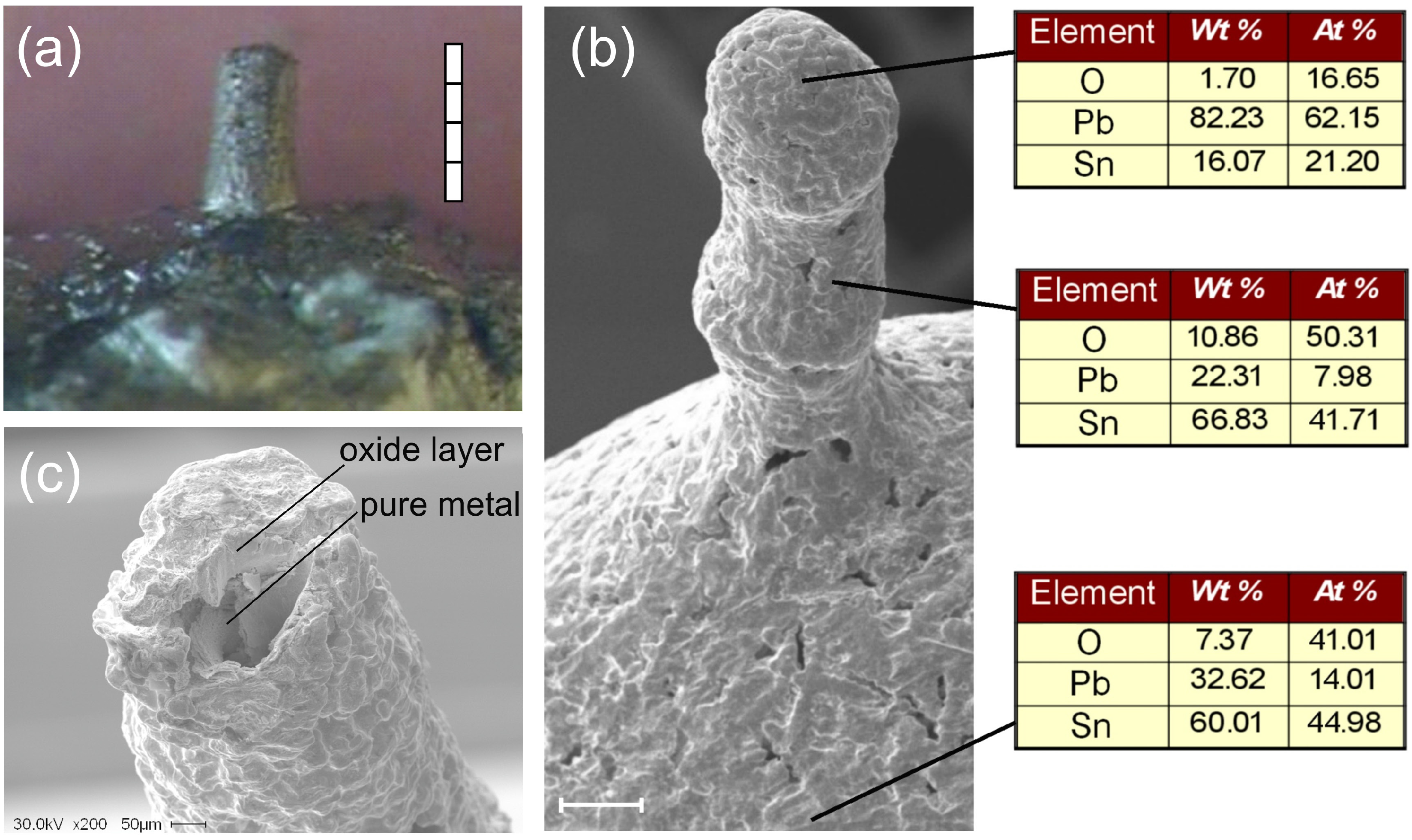
Figure 8a presents a typical microtower structure grown on a molten lead surface in air by 100 laser pulses of Nd:YAG laser. The structure diameters are typically 2–4 times larger than the irradiation spot size (depends mainly on laser fluence) while their length can be up to 2–3 mm. The limiting factors for the length are discussed below. Similar microtowers formed in different ambient gases at 1 bar (SF
6, air, and N
2) exhibit strong dependence of the growth rate on chemical activity of the ambient gas [
70]. The largest rate for liquid gallium in SF
6 environment (~9 μm/pulse) was at least ten times higher than in a nitrogen atmosphere. This indicates that the chemical reactivity of the ambient gas is a key parameter for the microtower growth.
It was found that the microtowers are tubes, which are composed of solid walls (metal oxide, nitride, or fluoride, depending on gas environment) filled by pure metallic material as was demonstrated by the SEM analysis in
Figure 8b,c. The SEM images correspond to a microtower, which was formed by Nd:YAG laser irradiation of a SnPb alloy target in air (pressure 1 bar,
T0 = 400 °C,
F0 = 3.2 J/cm
2, number of pulses 600). The elemental composition of the structure was determined by EDX using 30 keV electrons (O–K, Pb–M, and Sn–L lines),
Figure 8b. It is clearly seen that the surface layer of both the non-irradiated target sites and the microtower walls represents a porous oxide material. The surface of the molten target maintained at the enhanced temperature is highly oxidized outside the irradiation zone, and the microtower walls are also covered by oxidized metals with the SnPb:O ratio being very close to 1:1. However, the microtower tip is oxygen-deficient, compared to the microtower walls and the non-irradiated target sites. As the estimated penetration depth for 30 keV electrons is slightly less than 2 μm [
79], one may conclude that either the oxide layer on the microtower tip is much thinner than 2 μm or the oxide and metal are mixed due to complicated hydrodynamics within the laser irradiation spot during the ablation process [
80]. In view of the small lead content in the target (~20 atom %, [
81]), the dominance of lead on the microtower tip can be explained by the oxidation kinetics of tin [
82]. Tin is extremely stable with respect to oxidation in air at normal conditions. Slow oxidation is initiated only at temperatures higher than 150 °C and the oxidation rate increases rapidly with the temperature. However, at high temperatures, which are reached during pulsed laser ablation (up to several thousand of Kelvin), tin easily burns out with formation of gaseous tin dioxide leading to Pb enrichment at the hot zone. To further reveal the microtower tip structure, we performed multishot ablation of the microtower tip shown in
Figure 8b by Nd:YAG laser irradiation (
F0 = 3.2 J/cm
2) at room temperature. The tip unsealed by the laser is shown in
Figure 8c, demonstrating a layer of ~50-μm thick oxide, under which the pure SnPb alloy with initial composition is seen.
Figure 8.
(a) A microtower grown on a lead surface irradiated in air at T0 = 470 °C by 100 laser pulses of Nd:YAG laser, irradiation spot diameter of 100 μm. Scale bar is 0.8 mm. F0 = 3 J/cm2 per pulse. (b) SEM image of a SnPb alloy microtower and compositions of the surface layer at different sites of the microtower structure and on the molten target. The microtower has been grown in air with 600 pulses of Nd:YAG laser at F0 = 3.2 J/cm2. Scale bar is 200 μm. (c) The tip of microtower shown in (b) unsealed by multishot irradiation (F0 = 3.2 J/cm2) after its solidification at room temperature. A ~50-μm thick oxide envelop is seen to be filled with the pure SnPb alloy.
The scenario of tower-like structure growth has been revealed in [
70], which can be described on the example of ablation in air as follows. A drop of liquid metal being exposed to a chemically active atmosphere is covered by a solid layer of oxide. For laser wavelengths and fluences applied here for ablation, metal oxides are either transparent or have much smaller absorption coefficients compared to metallic solids [
60]. As a result, the laser pulse couples to the metal surface through the oxide film. As was shown by numerical simulations of molten metal ablation based on the thermal model [
60], laser-induced removal of material is rather negligible as compared to its protrusion during a single laser pulse. Due to the contact with the laser-heated metal, the film heats up and either thermally decomposes when reaching the decomposition temperature or, more probable, fractures under high thermal stresses [
83]. The metal layer within the irradiation spot thermally expands, partially vaporizes, and protrudes through the hole produced in the oxide shell by the laser. During the time interval between two subsequent pulses, the surface of the protruded metal is subjected to oxidation. We underline that the hot ambient gas and laser-produced plasma facilitate surface oxidation. The next laser pulse couples to the top part of the formed protrusion and again ablates a small amount of metal. A thin oxide film formed between the pulses is fractured in the top site and its debris is carried away with the laser ablation plume. As the bump top is now bare of oxide while its side walls are preserved, capillary forces (upon ablation vertically from the top) or liquid metal pressure (if the laser beam couples to the target horizontally) drive the liquid metal up through the formed oxide tube. When irradiation terminates, the produced microhorn is finally covered by an oxide layer (
Figure 8).
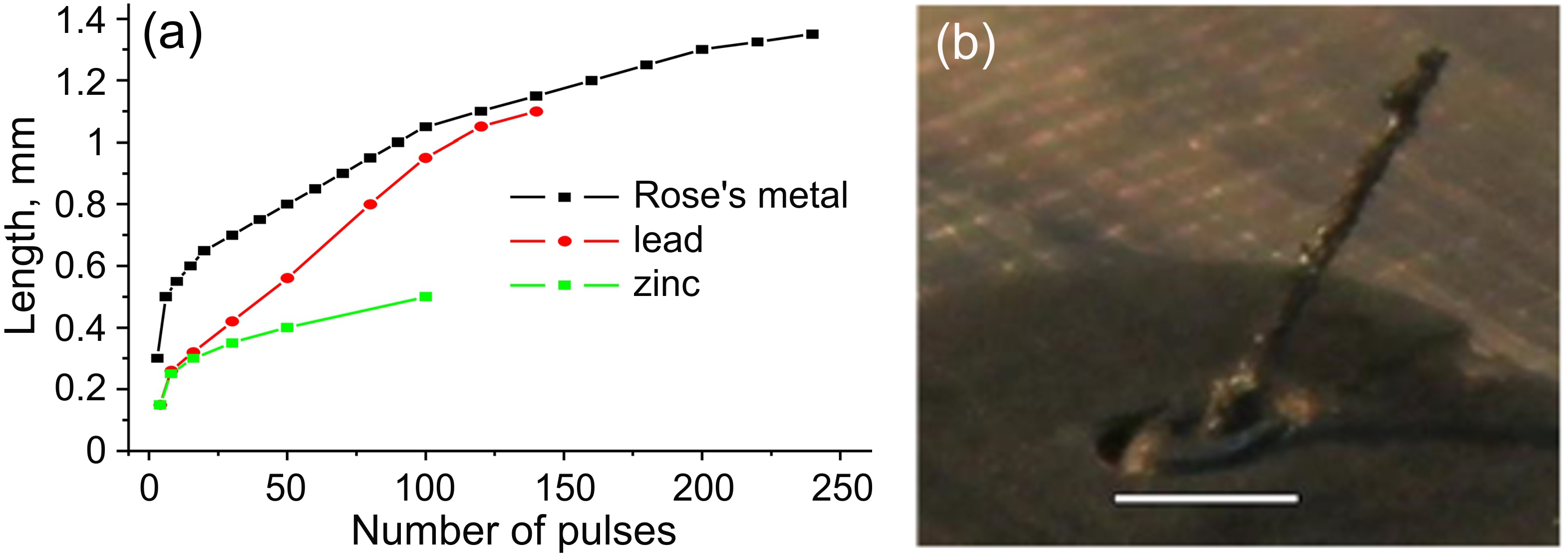
The results of comparative studies of the microtower length as a function of number of laser pulses are presented in
Figure 9a for Pb, Zn, and Rose’s metal. The structures were grown under identical irradiation conditions (air at 1 bar,
T0 = 30 °C, Nd:YAG laser,
F0 = 3.2 J/cm
2). The maximum growth rate is usually observed at the very beginning of irradiation and is supported during the first ten pulses (up to ~50 μm/pulse for Rose’s metal) whereupon the growth slows down. The absolute growth rate depends on the types of metal and ambient gas, target temperature, and laser fluence and wavelength. However, measurements carried out for different target temperatures indicate a rather weak temperature dependence of microtower growth. As an example, for gallium in the temperature range of 30–60 °C the structures grown with the same number of pulses were of the same length and some growth acceleration by 15%–20% was observed at increasing
T0 to ~250 °C. At the same time, increasing the laser fluence considerably enhanced the growth rate that points to the dominant role of laser heating of the molten material in the microtower formation process.
The main parameter that limits the microtower length is the strength of the chemically produced solid film covering the microstructure. At reaching a definite “critical” length, specific for each pair “metal–ambient gas”, the microtower breaks or is even sinking into the molten target [
70]. It was found that the higher is laser fluence, the longer structure can be grown. A higher temperature of a metal within the irradiation spot reached at higher laser fluence facilitates surface chemical reactions resulting in stronger and thicker walls of the forming capillary structure. At high laser fluences, the microstructure length can be grown up to several millimeters as shown in
Figure 9b. The microtower shown in the figure (“tower of Pisa”) was grown on the surface of GaIn alloy by the action of Nd:YAG-laser in air when irradiation spot size was decreased to 50 μm. After reaching 3 mm in length, the structure starts to sink into alloy depth. Note that decreasing the irradiation spot size has allowed to make the microtower thinner, to approximately 100–150 μm. By increasing the irradiation spot size, it was possible to increase the structure diameter to more than 1 mm.
The microtowers can be grown into a desired configuration as demonstrated in
Figure 10. In
Figure 10a, a microtower was first grown up to the length of ~1.3 mm and then was irradiated perpendicularly to its wall. As a result, a branch was formed of almost the same length as the parent structure. Note that the branched microtower is not broken in spite of its considerable weight. This can be explained by the fact that the target reorientation for laser irradiation of the parent microtower wall took some time during which the continuing oxidation process “annealed” the structure.
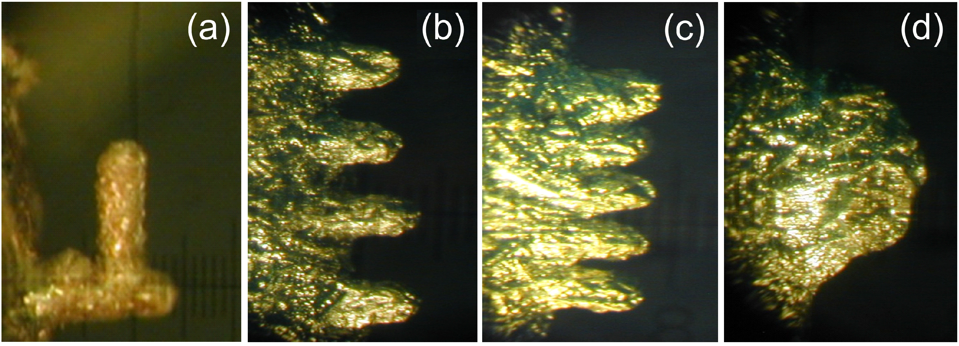
Figure 10b,c shows a series of microstructures grown with different distances between irradiation spot sizes from complete separation (b) to minor (c) and strong (d) overlapping.
Figure 9.
(a) Microtower length as a function of number of laser pulses for three metals. Nd-YAG laser, F0 = 3 J/cm2 per pulse, T0 = 550 °C, irradiation spot diameter of 100 μm. (b) An example of microtower structure grown on the surface of GaIn alloy by the action of Nd:YAG-laser in air at the irradiation spot diameter of 50 μm and F0 = 12 J/cm2. Scale bar is 1 mm.
Figure 10.
Examples of microstructures grown on liquid metal surfaces by irradiation with the second harmonics of Nd:YAG laser in air at F0 = 3.2 J/cm2. (a) A branched structure grown on a liquid gallium target at the ambient temperature T0 = 30 °C. The parent microtower (horizontal) was grown with 250 laser pulses and the branch was formed by laser beam focused perpendicularly to the parent microtower wall during the next 250 pulses. (b)–(d) Microtower “fences” grown on Wood’s metal at T0 = 250 °C with different spatial separations of the irradiation spots. The distances between the spot centers are approximately two spot diameters (b), one spot diameter (c), and spot radius (d).
The described microstructures can open ways for a number of possible applications, among which we can conceive of manufacturing a variety of microparts, moulds, and decorations. Another application may be in studying the chemistry of surface reactions under strongly nonequilibrium conditions, in particular the role of laser plasma in facilitating the surface chemical. As an example, we can conjecture that the mechanism of microcones growth [
84] can have similar features to those responsible for microtower formation. It must be admitted that ablated material can also be oxidized in the gas phase and redeposit on the target surface, participating in formation of oxide film. Next section presents results of experimental and numerical studies of laser backward deposition of nanostructured films where the plasma plume dynamics plays the determining role.
6. Backward Deposition of Ablation Products
Optimisation and control of laser-induced surface modification for various applications (improvement of surface hardness, wear and corrosion resistance, enhancement of adhesive properties,
etc.) require deep understanding of the physical processes involved in laser treatment of materials. Laser plasma formation can play a key role in laser processing of surfaces as was already shown in
Section 3 and
Section 4. Here we address the backward deposition of ablation products as the formation of a deposited layer strongly affects the properties of surfaces after laser processing. Backward deposition of the ablated product around the laser-irradiated area is a known effect for polymer ablation [
85], synthesis of silicon nanoclusters [
86,
87], modification of steel surfaces by backward deposit resulting in change of surface properties in terms of adhesion or mechanical characteristics [
88].
Upon laser processing under normal atmosphere, redeposition of the ablation products is almost unavoidable [
19,
29,
35,
36]. The complicated hydrodynamics of the ablation plume with formation of shock waves and vortical structures brings ablated particles back to the irradiated surface [
19,
31,
89,
90]. During mixing with air, ablated particles can experience oxidation and form clusters. The oxidation process of metal vapour and metallic surfaces is effective in the presence of plasma [
91] while the vortical plume motion ensures mixing of the ablation products with air oxygen. As a result, the redeposited material represents a nanostructured oxide layer. In [
89], detailed studies of surface nanostructuring was reported for steel samples irradiated by a XeCl excimer laser (308 nm, pulse duration of 25 ns) in air under atmospheric pressure. Due to the high pressure of the surrounding gas, the laser-produced plasma remains confined close to the sample surface, so that the ablated and formed within the plume species are deposited around the spot area by backward flux (
Figure 11a). The morphological and chemical analysis revealed that the surface could be described as a nanostructured layer of iron oxide nanoparticles covering the thermally oxidized layer. By time-resolved ICCD imaging, the vortical motion was clearly observed in the plume as shown in
Figure 10c.
Vortical structures were also obtained in a number of modeling attempt to describe laser-induced plume expansion in an ambient atmosphere [
31,
90,
92,
93,
94]. Due to complexity of hydrodynamics, the most of attempts are based on the Euler equations and does not take into account interdiffusion and mixing of the ablation products with the ambient gas. Recently, we have developed a model of plasma plume expansion in an ambient gas based on the complete set of the Navier-Stokes equations taking into account interdiffusion of the gaseous components. Note that taking into account the diffusion process requires a modification of the momentum and energy equations as the diffusion process affects the energy and momentum transfer. The model was successfully applied to PMMA ablation [
90]. Here we report application of this model to the experimental conditions of [
89]. The details of the model, including numerical scheme, are described in [
90]. Here we give only its main features in application to ablation of the metallic surface under study.
For simplicity, the problem was considered as an impulsive vaporization of Fe atoms from the irradiated surface into air under the atmospheric pressure. It was assumed that a 120-nm layer of the Fe sample is vaporized uniformly in time from a spot of 1.5 mm in diameter during the laser pulse action. The problem was solved for the cylindrically symmetric case. The temperature of the ablated plume was estimated by thermal modeling taking into account laser light absorption in the laser-produced plasma [
6,
40,
42]. It was found that, at
F0 = 10 J/cm
2, the temperature can reach the level of ~25,000 K, due to strong absorption of the laser energy by the plume. Note, that under such conditions, the plume is substantially ionized and its temperature is much higher than that of the vaporized surface sites. After laser pulse termination, the Fe atom supply from the target was stopped and further dynamics of the ablation plume expansion in air was simulated. It is worth noting that, due to the dense atmosphere, the adhesion boundary conditions are used at the solid boundaries that are the equality of the temperature of the target and the gas species as well as zero velocity of the gas particles in the nearest proximity of the wall (non-slip condition).
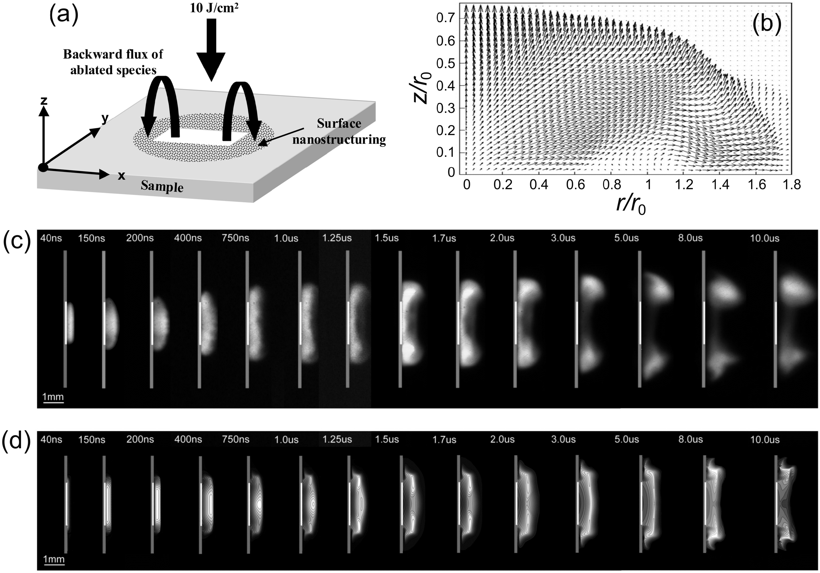
Figure 11.
(
a) A schematic diagram of backward deposition during surface ablation in ambient air [
89]. (
b) The calculated vector field of the mixing ablation products and air at 1 μs after laser irradiation under the conditions of [
89] (laser wavelength of 308 nm, pulse duration of 25 ns, fluence of 10 J/cm
2) showing a tendency of massive material redeposition on the targets beyond the irradiation spot of radius
r0. (
c) Time resolved ICCD imaging from the plume produced by steel ablation in ambient air. Irradiation conditions are as in (
b). The gate of the ICCD camera was 30 ns, time delays with respect to the laser pulse are indicated in the images. (
d) The spatial distribution of the density of Fe atoms in the axial plane obtained by modeling. The lighter is the tone, the higher is the density. The simulations were performed for the experimental conditions [
89] shown in (
c).
In
Figure 11b, the flow field obtained numerically is shown for the time moment of 1 μs after the laser pulse termination. It demonstrates dominating expansion in the radial direction and signs of formation of a vortical motion. In
Figure 11d, the snapshots of the density of iron atoms are given for the same time moments as in the experimental images of the plume luminescence,
Figure 11c. As a whole, the dynamics of the plume expansion can be summarized as follows. According to both experimental observations and modeling (
Figure 11c,d), at early times, before ~250 ns after the laser pulse termination, the ablation plume expands predominantly in the direction from the target pushing the surrounding gas molecules. As a result, the ablated species and the ambient gas are compressed that leads to a decrease of the ablated species energy and, thus, impedes the expansion of the plasma plume in the axial direction. At this stage, the plume-background interaction is similar to the snow-plow effect noticed earlier for laser ablation at relatively high pressures [
95]. After ~250 ns, the plume starts expanding predominantly in the radial directions due to a high pressure created in front of the expending plasma by the snow-plow effect. Already at 1 µs (
Figure 11b) some signs of vortex formation are seen due to the boundary layer and viscosity effects typical for a gas jet issuing into a background gas. A similar vortical motion with wide radial spreading of the ablation species was also observed experimentally [
96] and obtained numerically [
90] for the case of PMMA ablation. Note that namely the radial plume spreading and development of vortical structures at the plasma plume periphery are responsible for efficient backward deposition. Striking is that, by varying the laser ablation conditions, it is possible to create the “plasma pipe”, which directs the ablation species away from the target (
Section 2) and, in contrast, to facilitate redeposition of the ablation species back to the target surface, in particular well beyond the irradiation spot edges [
89].

 ,
, 