The Effect of Inertia on the Flow and Mixing Characteristics of a Chaotic Serpentine Mixer †


Abstract
:
1. Introduction
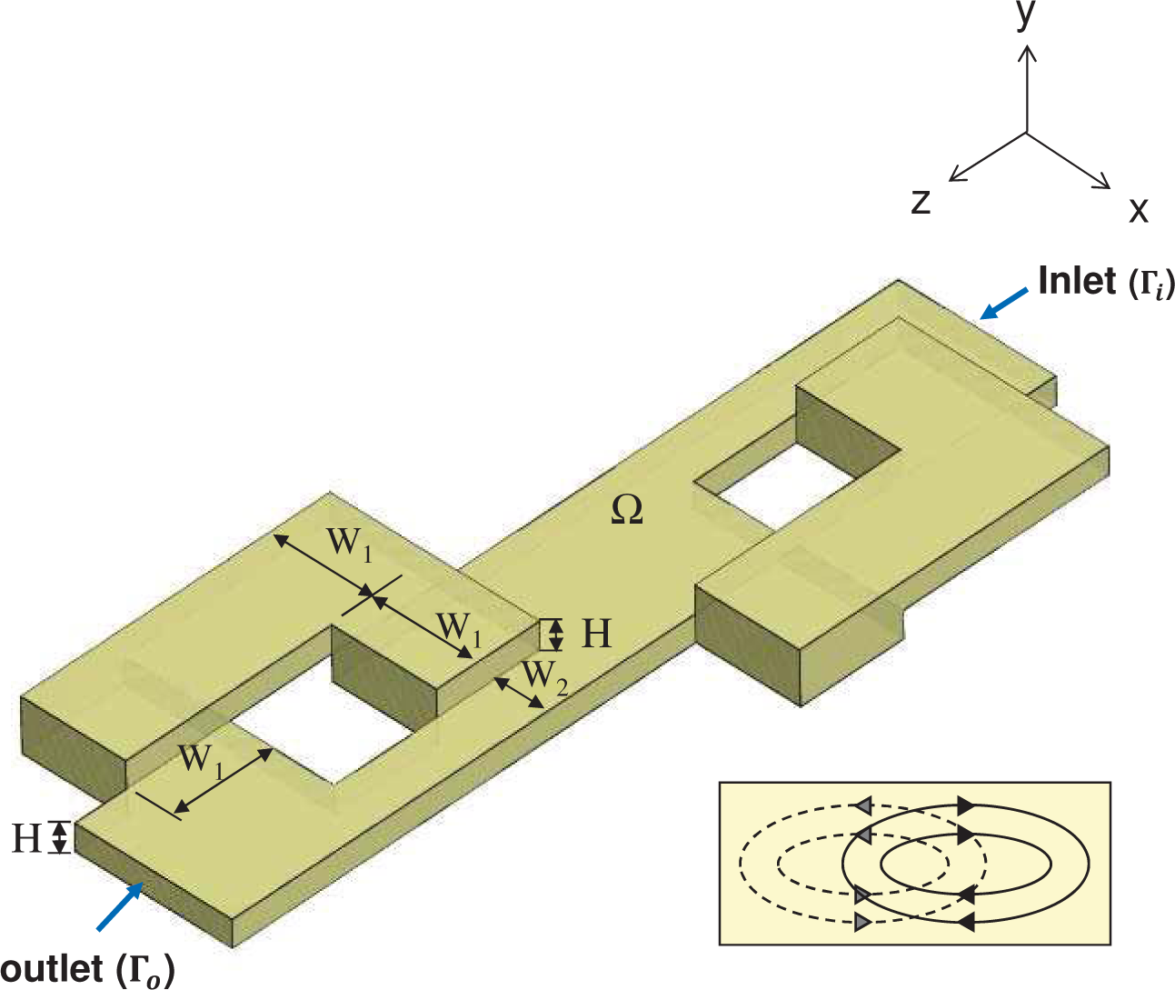
2. Mixer Geometry
3. Modeling and Numerical Methods
4. Results and Discussion
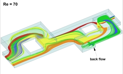
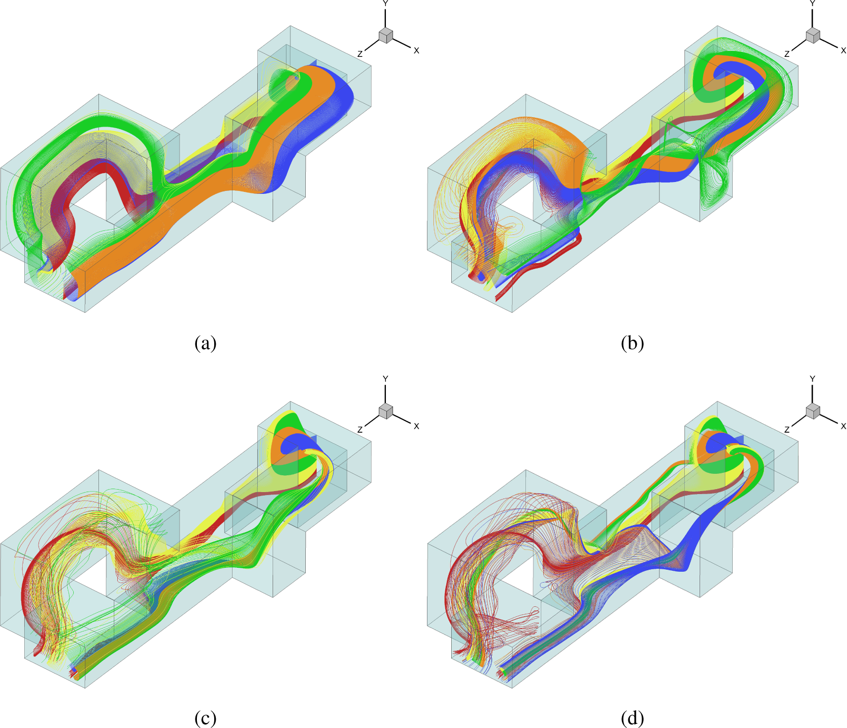
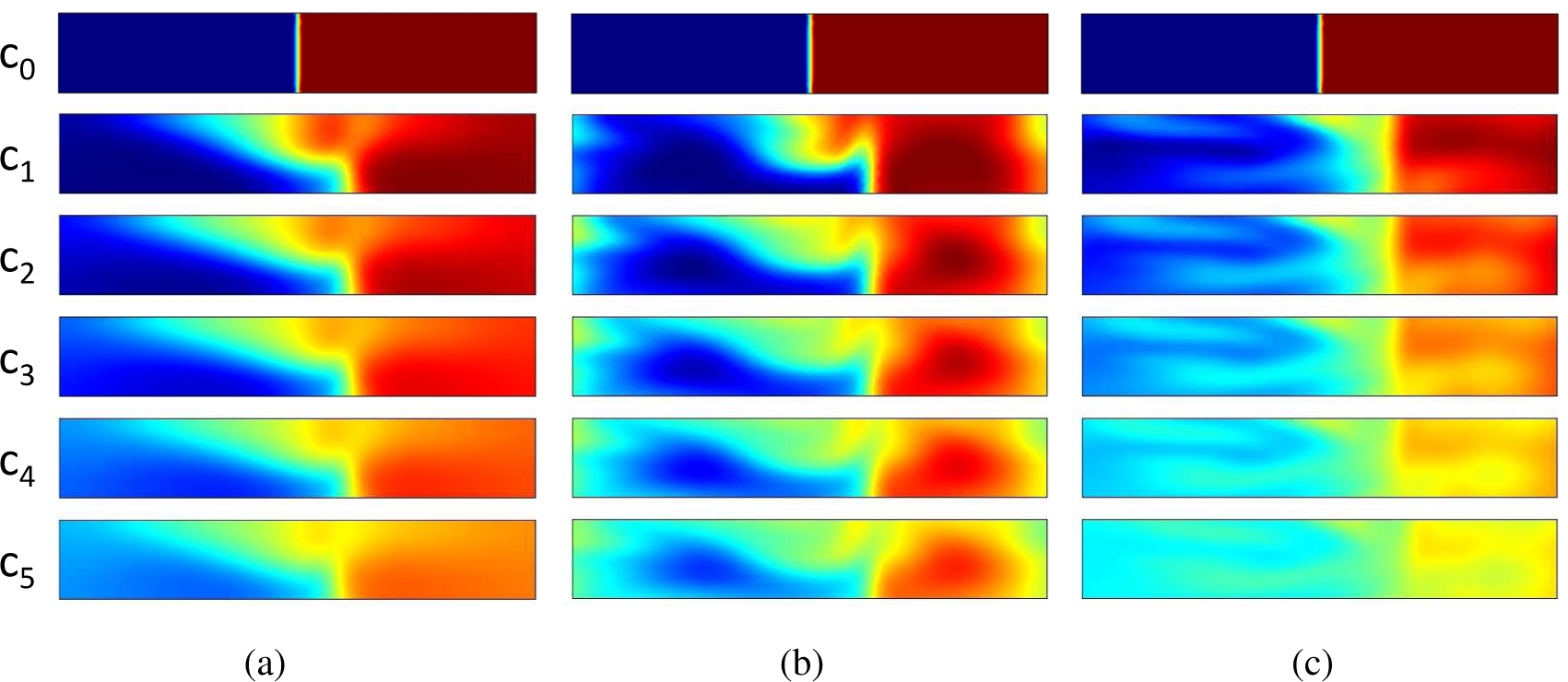
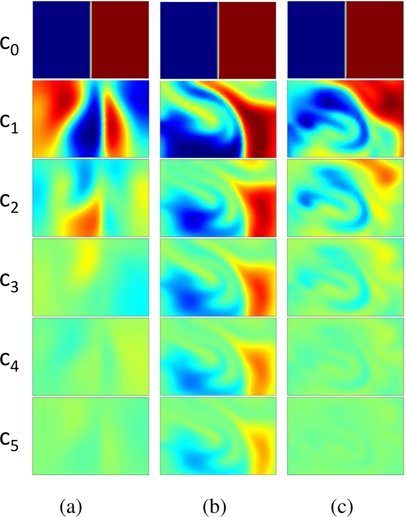
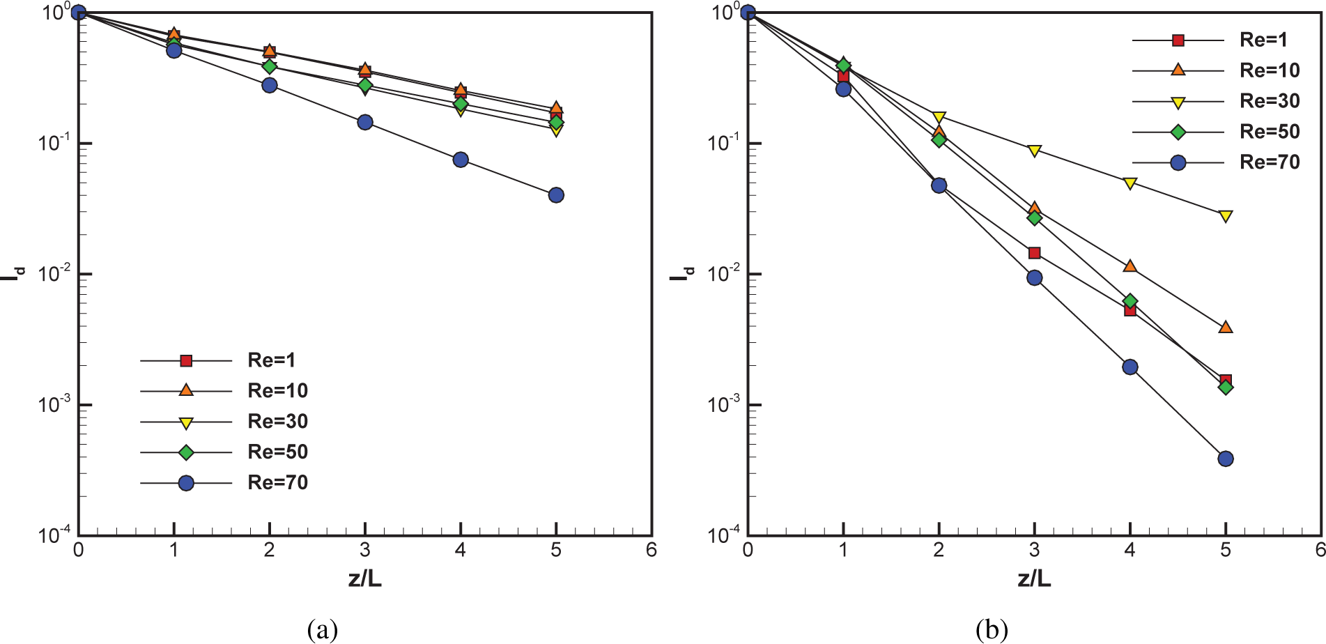
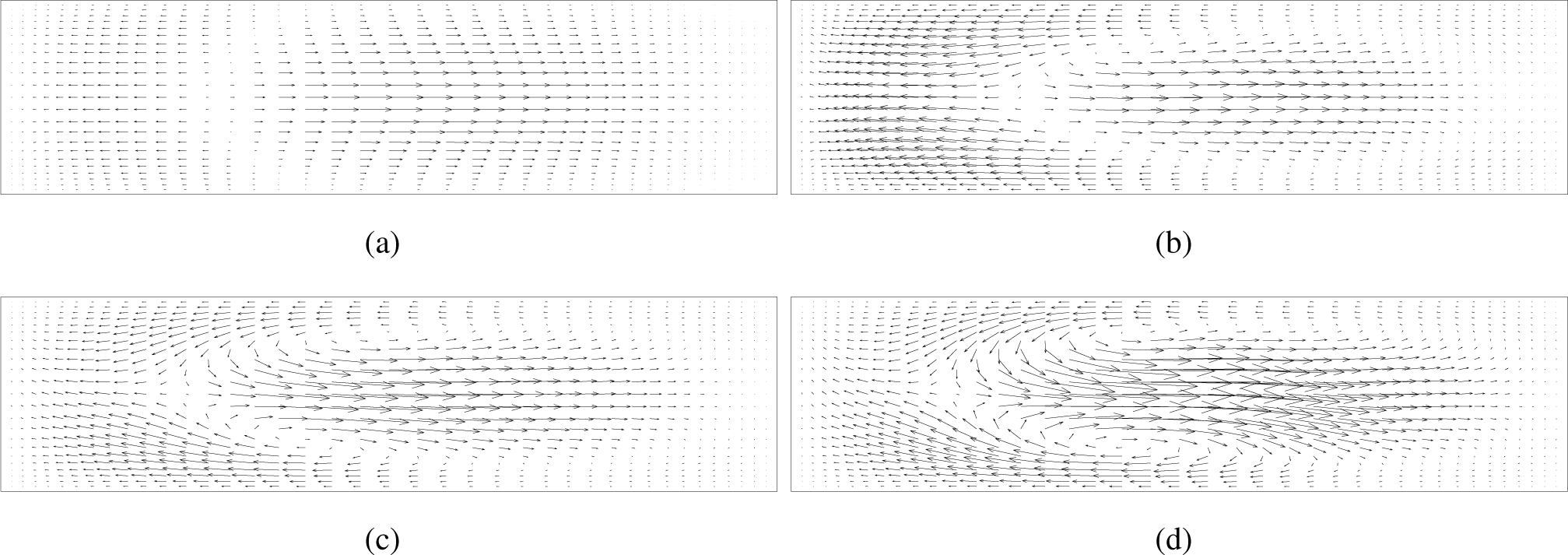
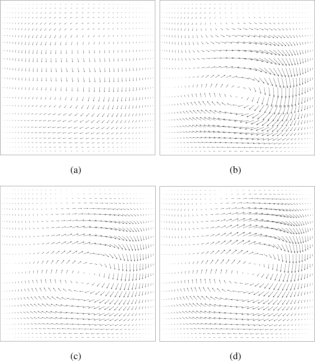
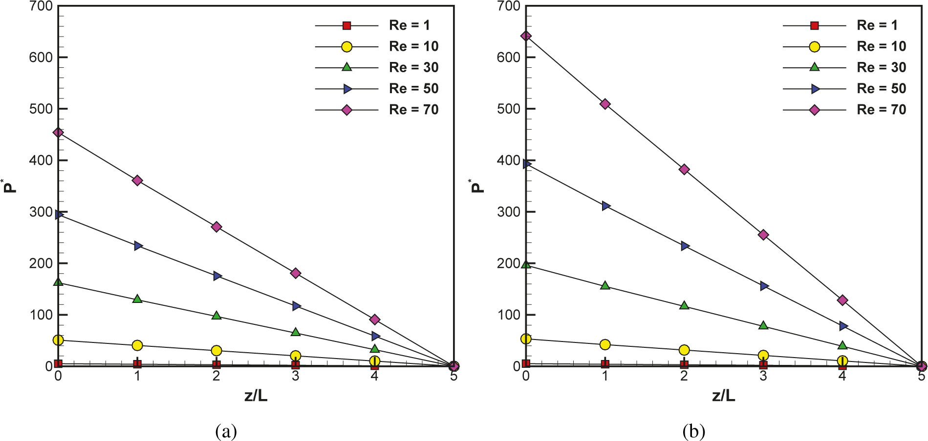
4.1. Flow Characteristics
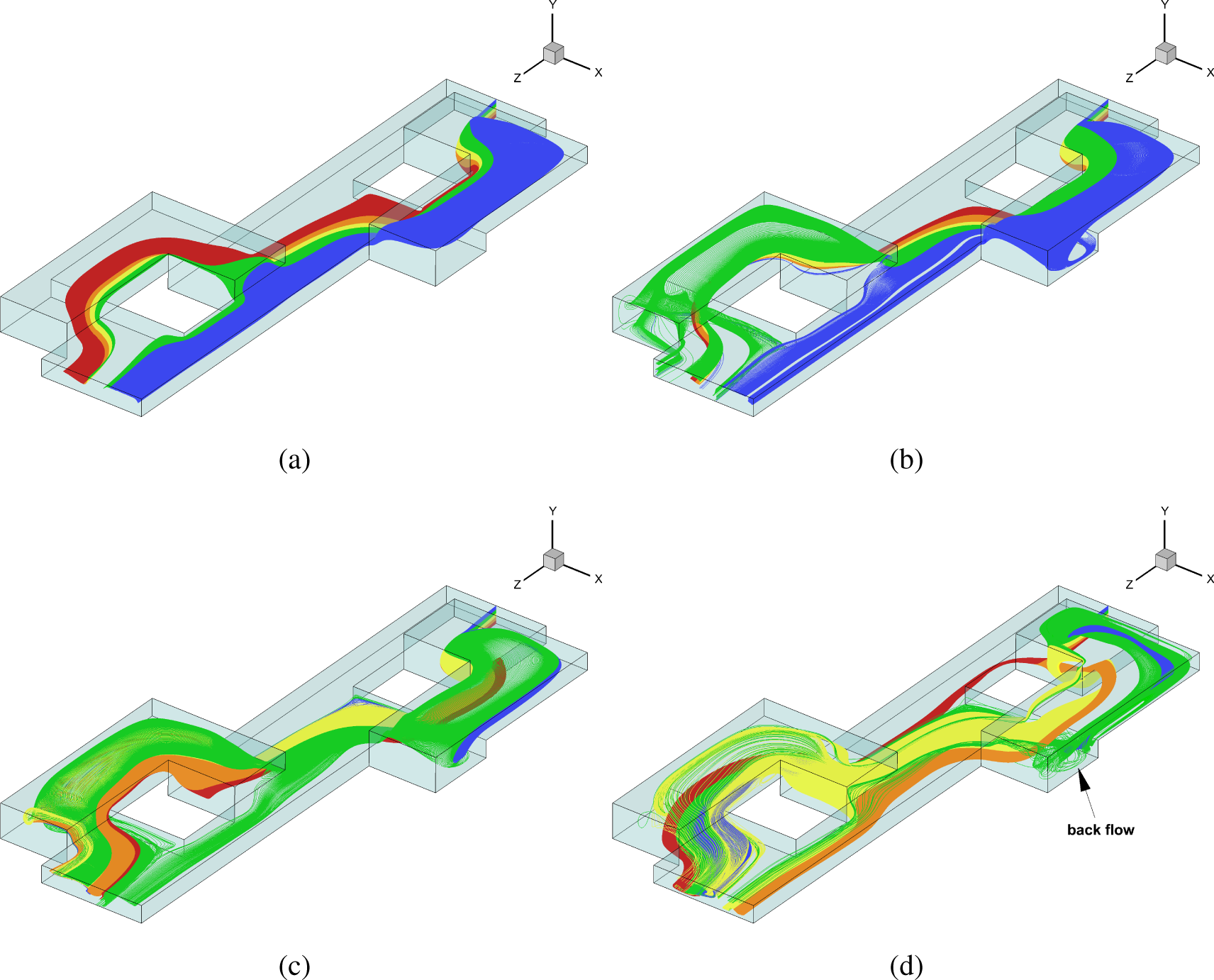
4.2. Interface Tracking
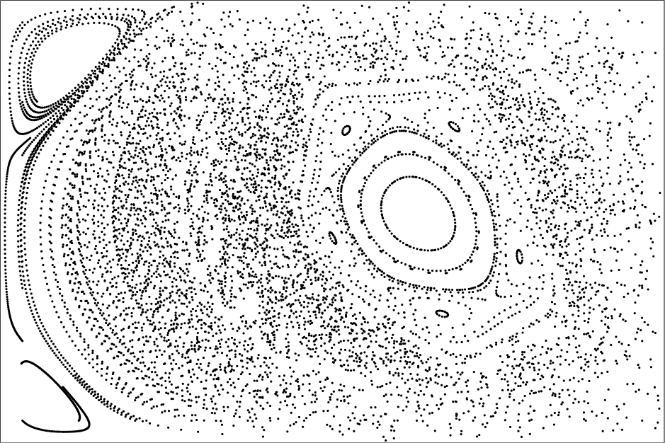
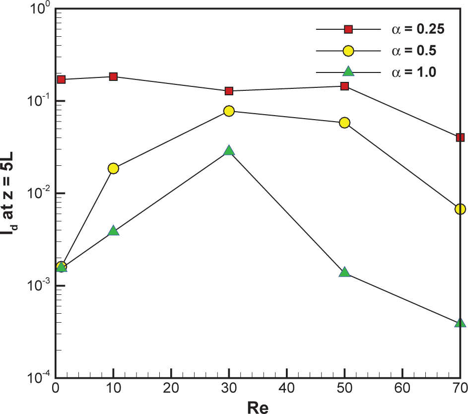
4.3. Mixing Analysis
5. Conclusions
Acknowledgments
Author Contributions
Conflicts of Interest
- †This paper is an extended version of our paper published in Asian Conference on Mixing 2010, Jeju, Korea, 19–22 October 2010.
References
- Ottino, J.M.; Wiggins, S. Introduction: Mixing in microfluidics. Phil. Trans. R. Soc. Lond. A 2004, 362, 923–935. [Google Scholar]
- Nguyen, N.T.; Wu, Z. Micromixers—A review. J. Micromech. Microeng 2005, 15, R1–R16. [Google Scholar]
- Hessel, V.; Löwe, H.; Schönfeld, F. Micromixers—A review on passive and active mixing principles. Chem. Eng. Sci 2005, 60, 2479–2501. [Google Scholar]
- Suh, Y.K.; Kang, S. A review on mixing in microfluidics. Micromachines 2010, 1, 82–111. [Google Scholar]
- Stone, H.A.; Kim, S. Microfluidics: Basic issues, applications, and challenges. AIChE J 2001, 47, 1250–1254. [Google Scholar]
- Stone, H.A.; Stroock, A.D.; Ajdari, A. Engineering flows in small devices: Microfluidics toward a Lab-on-a-chip. Annu. Rev. Fluid Mech 2004, 36, 381–411. [Google Scholar]
- Aref, H. Stirring by chaotic advection. J. Fluid Mech 1984, 143, 1–21. [Google Scholar]
- Ottino, J.M. The Kinematics of Mixing: Stretching, Chaos, and Transport; Cambridge University Press: Cambridge, UK, 1989. [Google Scholar]
- Ottino, J.M. Mixing, chaotic advection, and turbulence. Annu. Rev. Fluid Mech 1990, 22, 207–253. [Google Scholar]
- Wiggins, S.; Ottino, J.M. Foundations of chaotic mixing. Phil. Trans. R. Soc. Lond. A 2004, 362, 937–970. [Google Scholar]
- Bertsch, A.; Heimgartner, S.; Cousseau, P.; Renaud, P. Static micromixers based on large-scale industrial mixer geometry. Lab Chip 2001, 1, 56–60. [Google Scholar]
- Stroock, A.D.; Dertinger, S.K.; Ajdari, A.; Mezić, I.; Stone, H.A.; Whitesides, G.M. Chaotic mixer for microchannels. Science 2002, 295, 647–651. [Google Scholar]
- Kim, D.S.; Lee, S.W.; Kwon, T.H.; Lee, S.S. A Barrier embedded chaotic micromixer. J. Micromech. Microeng 2004, 14, 798–805. [Google Scholar]
- Chen, H.; Meiners, J.C. Topologic mixing on a microfluidic chip. Appl. Phys. Lett 2004, 84, 2193–2195. [Google Scholar]
- Liu, R.H.; Stremler, M.A.; Sharp, K.V.; Olsen, M.G.; Santiago, J.G.; Adrian, R.J.; Aref, H.; Beebe, D.J. Passive mixing in a three-dimensional serpentine microchannel. J. Microelectromech. Syst 2000, 9, 190–197. [Google Scholar]
- Kim, D.S.; Lee, S.H.; Kwon, T.H.; Ahn, C.H. A serpentine laminating micromixer combining splitting/recombination and advection. Lab Chip 2005, 5, 739–747. [Google Scholar]
- Kang, T.G.; Singh, M.K.; Kwon, T.H.; Anderson, P.D. Chaotic mixing using periodic and aperiodic sequences of mixing protocols in a micromixer. Microfluid. Nanofluid 2008, 4, 589–599. [Google Scholar]
- Lin, H.; Storey, B.D.; Oddy, M.H.; Chen, C.H.; Santiago, J.G. Instability of electrokinetic microchannel flows with conductivity gradients. Phys. Fluids 2004, 16, 1922–1935. [Google Scholar]
- Sritharan, K.; Strobl, C.J.; Schneider, M.F.; Wixforth, A.; Guttenberg, Z. Acoustic mixing at low Reynold’s numbers. Appl. Phys. Lett 2006, 88, 054102. [Google Scholar]
- Khatavkar, V.V.; Anderson, P.D.; den Toonder, J.M.J.; Meijer, H.E.H. Active micromixer based on artificial cilia. Phys. Fluids 2007, 19, 083605. [Google Scholar]
- Kang, T.G.; Hulsen, M.A.; Anderson, P.D.; den Toonder, J.M.; Meijer, H.E. Chaotic advection using passive and externally actuated particles in a serpentine channel flow. Chem. Eng. Sci 2007, 62, 6677–6686. [Google Scholar]
- Kang, T.G.; Hulsen, M.A.; Anderson, P.D.; den Toonder, J.M.J.; Meijer, H.E.H. Chaotic mixing induced by a magnetic chain in a rotating magnetic field. Phys. Rev. E 2007, 76, 066303. [Google Scholar]
- Den Toonder, J.M.J.; Bos, F.M.; Broer, D.J.; Filippini, L.; Gillies, M.; de Goede, J.; Mol, T.; Reijme, M.A.; Talen, W.; Wilderbeek, H.; Khatavkar, V.; Anderson, P.D. Artificial cilia for active micro-fluidic mixing. Lab Chip 2008, 6, 533–541. [Google Scholar]
- Phelan, F.R.; Hughes, N.R.; Pathak, J.A. Chaotic mixing in microfluidic devices by oscillatory cross flow. Phys. Fluids 2008, 20, 023101. [Google Scholar]
- Kang, T.G.; Singh, M.K.; Anderson, P.D.; Meijer, H.E.H. A chaotic serpentine mixer efficient in the creeping flow regime: From design concept to optimization. Microfluid. Nanofluid 2009, 7, 783–794. [Google Scholar]
- Park, J.M.; Kwon, T.H. Numerical characterization of three-dimensional serpentine micromixers. AIChE J 2008, 54, 1999–2008. [Google Scholar]
- Park, J.M.; Kim, D.S.; Kang, T.G.; Kwon, T.H. Improved serpentine laminating micromixer with enhanced local advection. Microfluid. Nanofluid 2008, 4, 513–523. [Google Scholar]
- Sturman, R.; Ottino, J.M.; Wiggins, S. The Mathematical Foundations of Mixing: The Linked Twist Map as a Paradigm in Applications: Micro to Macro, Fluids to Solids; Cambridge University Press: Cambridge, UK, 2006. [Google Scholar]
- Kang, T.G.; Kwon, T.H. Colored particle tracking method for mixing analysis of chaotic micromixers. J. Micromech. Microeng 2004, 14, 891–899. [Google Scholar]
- Singh, M.K.; Kang, T.G.; Anderson, P.D.; Meijer, H.E.H. The mapping method as a toolbox to analyze, design, and optimize micromixers. Microfluid. Nanofluid 2008, 5, 313–325. [Google Scholar]
- Schenk, O.; Gärtner, K. Solving unsymmetric sparse systems of linear equations with PARDISO. Futur. Gener. Comp. Syst 2004, 20, 475–487. [Google Scholar]
- Brooks, A.N.; Hughes, T.J. Streamline upwind/Petrov-Galerkin formulations for convection dominated flows with particular emphasis on the incompressible Navier-Stokes equations. Comput. Methods Appl. Mech. Eng 1982, 32, 199–259. [Google Scholar]
- Schönfeld, F.; Hessel, V.; Hofmann, C. An optimised split-and-recombine micro-mixer with uniform “chaotic” mixing. Lab Chip 2004, 4, 65–69. [Google Scholar]
- Danckwerts, P.V. The definition and measurement of some characteristics of mixtures. Appl. Sci. Res. A 1952, 3, 279–296. [Google Scholar]
- Meijer, H.E.H.; Singh, M.K.; Anderson, P.D. On the performance of static mixers: A quantitative comparison. Prog. Polym. Sci 2012, 37, 1333–1349. [Google Scholar]


© 2014 by the authors; licensee MDPI, Basel, Switzerland This article is an open access article distributed under the terms and conditions of the Creative Commons Attribution license (http://creativecommons.org/licenses/by/4.0/).
Share and Cite
Kang, T.G.; Anderson, P.D. The Effect of Inertia on the Flow and Mixing Characteristics of a Chaotic Serpentine Mixer. Micromachines 2014, 5, 1270-1286. https://doi.org/10.3390/mi5041270
Kang TG, Anderson PD. The Effect of Inertia on the Flow and Mixing Characteristics of a Chaotic Serpentine Mixer. Micromachines. 2014; 5(4):1270-1286. https://doi.org/10.3390/mi5041270
Chicago/Turabian StyleKang, Tae Gon, and Patrick D. Anderson. 2014. "The Effect of Inertia on the Flow and Mixing Characteristics of a Chaotic Serpentine Mixer" Micromachines 5, no. 4: 1270-1286. https://doi.org/10.3390/mi5041270