Magnetic Shape Memory Microactuators

 ,
,
Abstract
:1. Introduction

2. Combining MSMA Materials and MEMS Technologies
2.1. MSMA Foils
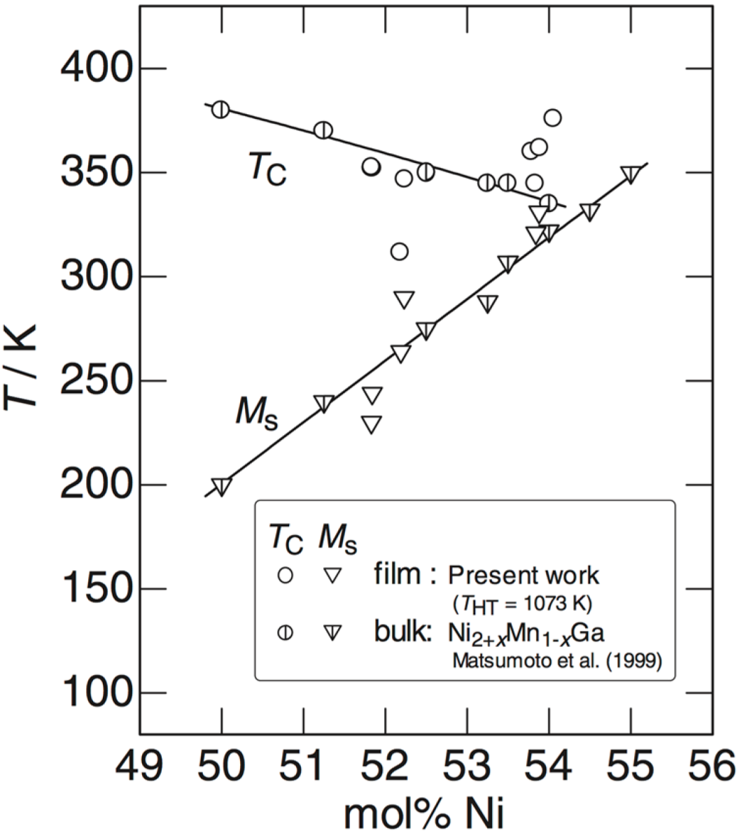
2.2. MSMA Films
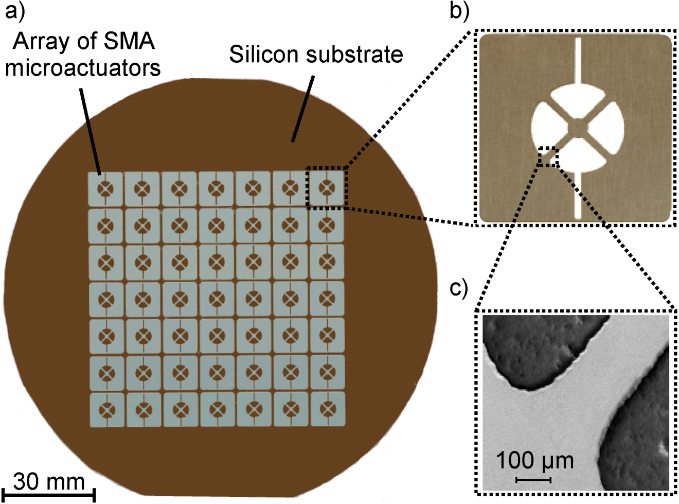
2.3. Integrated MSMA Film and Foil Microstructures

 | The freestanding MSMA film/foil is bonded onto a silicon substrate (bonding layer). Alternatively, the MSMA film is deposited by magnetron sputtering on a buffer layer. |
 | A gold layer is sputtered onto the MSMA layer for use as a hard mask. |
 | Optical lithography: A positive resist is spin coated onto the Au layer, exposed by UV light, and developed. |
 | The Au hard mask is patterned by wet chemical etching via the resist mask. |
 | The MSMA layer is micromachined by wet-chemical etching (e.g., hydrofluoric acid, nitric acid, and deionized water [33]). The hard mask is removed afterwards. |
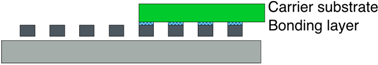 | Free-standing MSMA microactuators are released from the substrate by selective removal of the sacrificial layer. The microactuators may be selectively transferred to another substrate by bonding and release technology [30,31]. |

3. Actuation Principles and Demonstrators
| Coupling effect | Actuation mechanism | Reference |
|---|---|---|
| Magnetic field-induced reorientation (MIR) of martensite | Magnetic shape memory (MSM) actuation | [4] |
| Temperature gradient-induced martensitic transformation | Single phase boundary actuation | [34] |
| Thermally induced ferromagnetic transition and martensitic transformation | Bidirectional magnetostatic and thermoelastic actuation | [35] |
| Thermally induced metamagnetic transition | Thermomagnetic actuation | [36] |
| Magnetic stray-field-induced microstructure | Magnetic stray-field induced actuation | [37] |
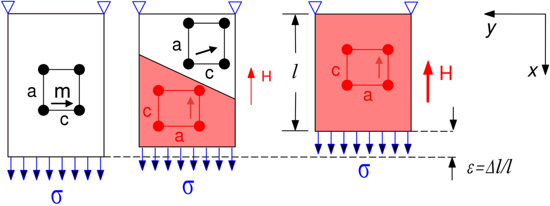
3.1. Magnetic Shape Memory Actuation
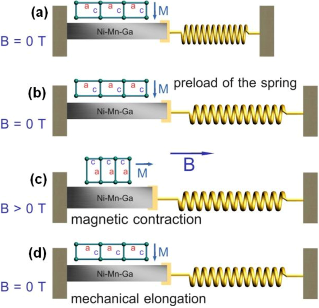
3.1.1. Operation Principle

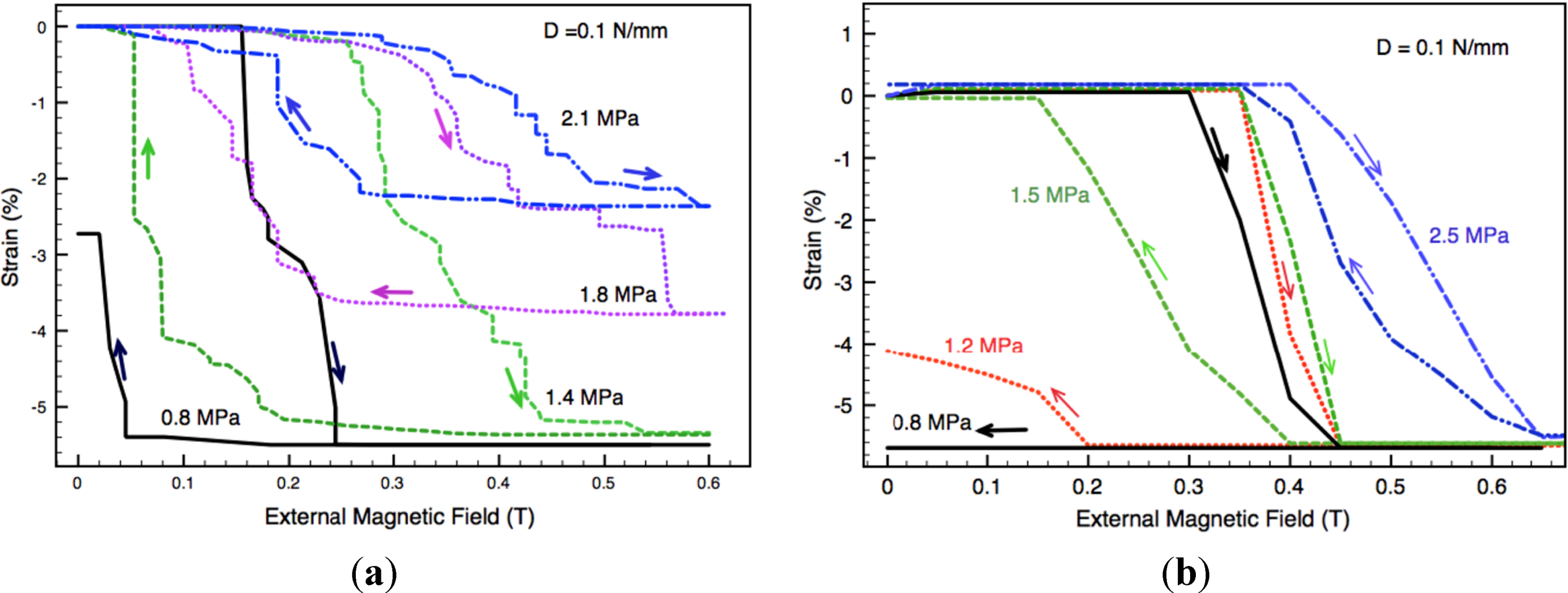
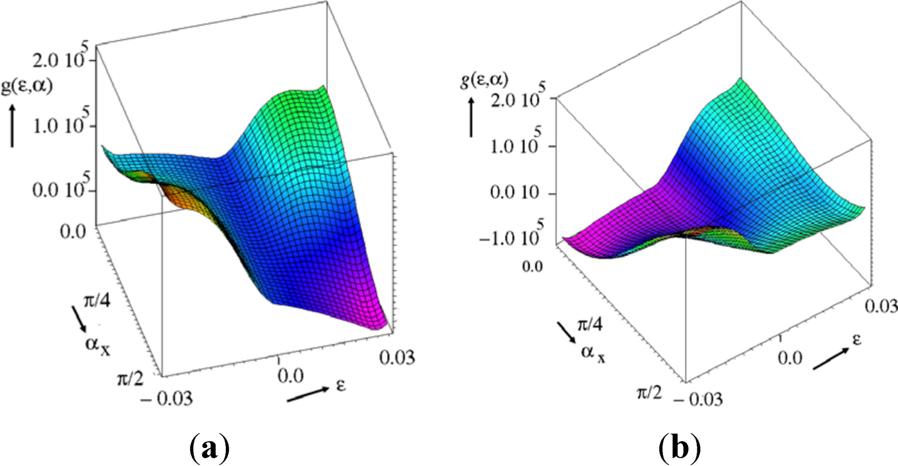
3.1.2. Simulation of MSM Actuation
3.1.3. MSM Linear Actuators

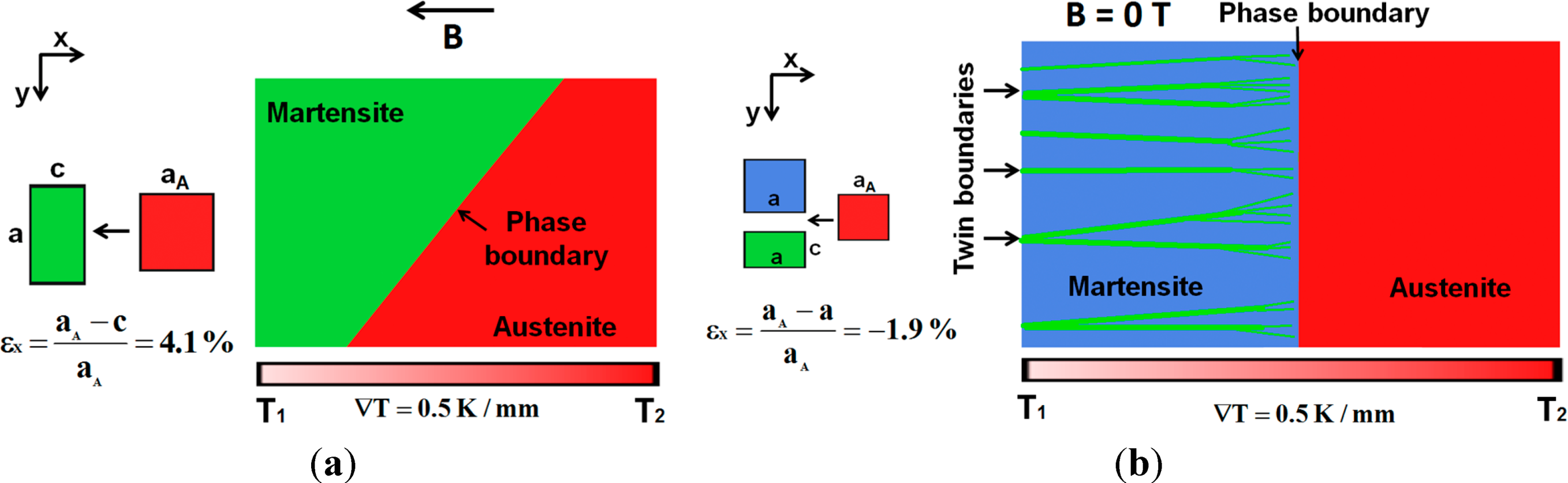
3.2. Single Phase Boundary Actuation
3.2.1. Operation Principle
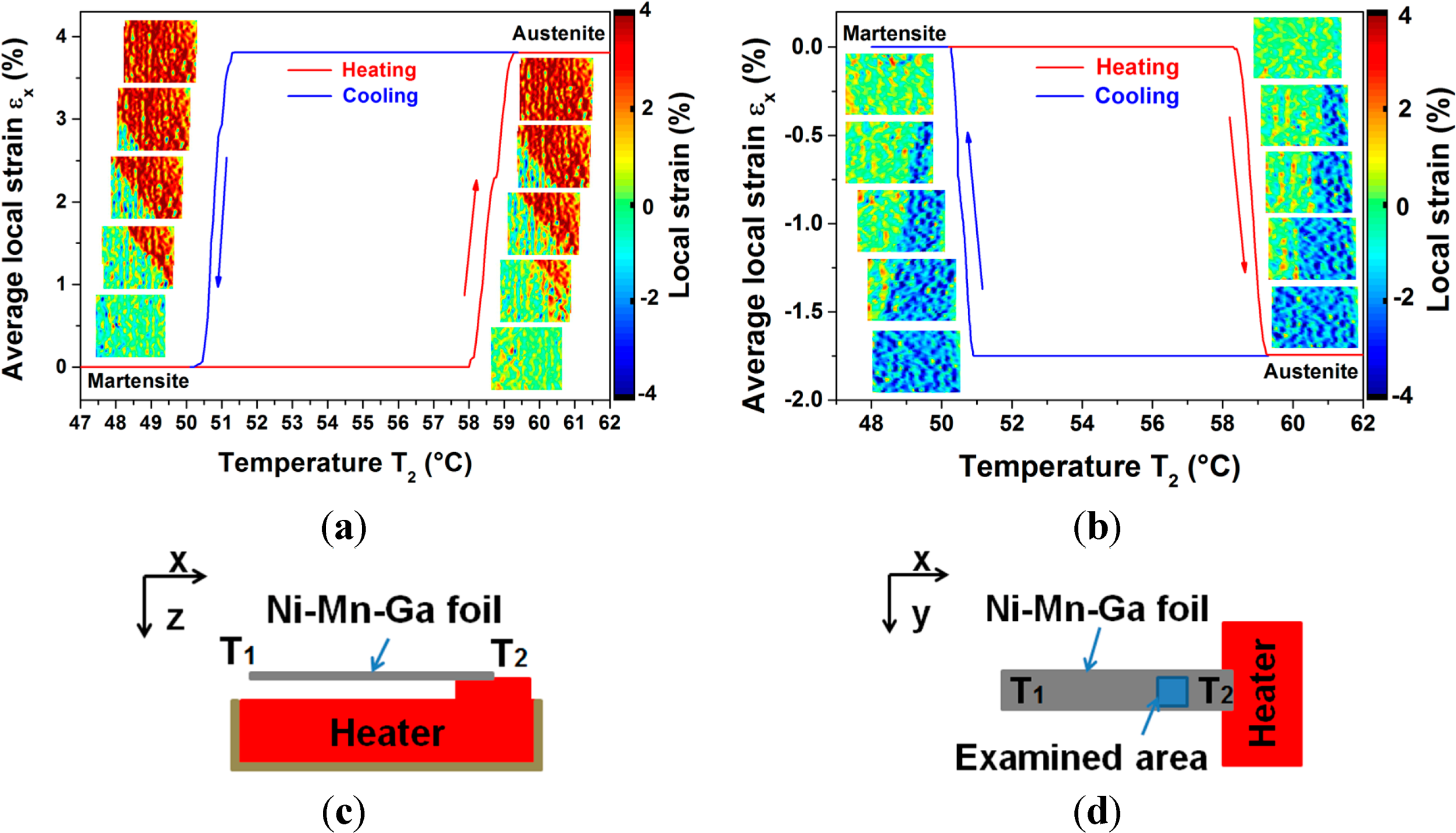
3.2.2. Mechanical Performance
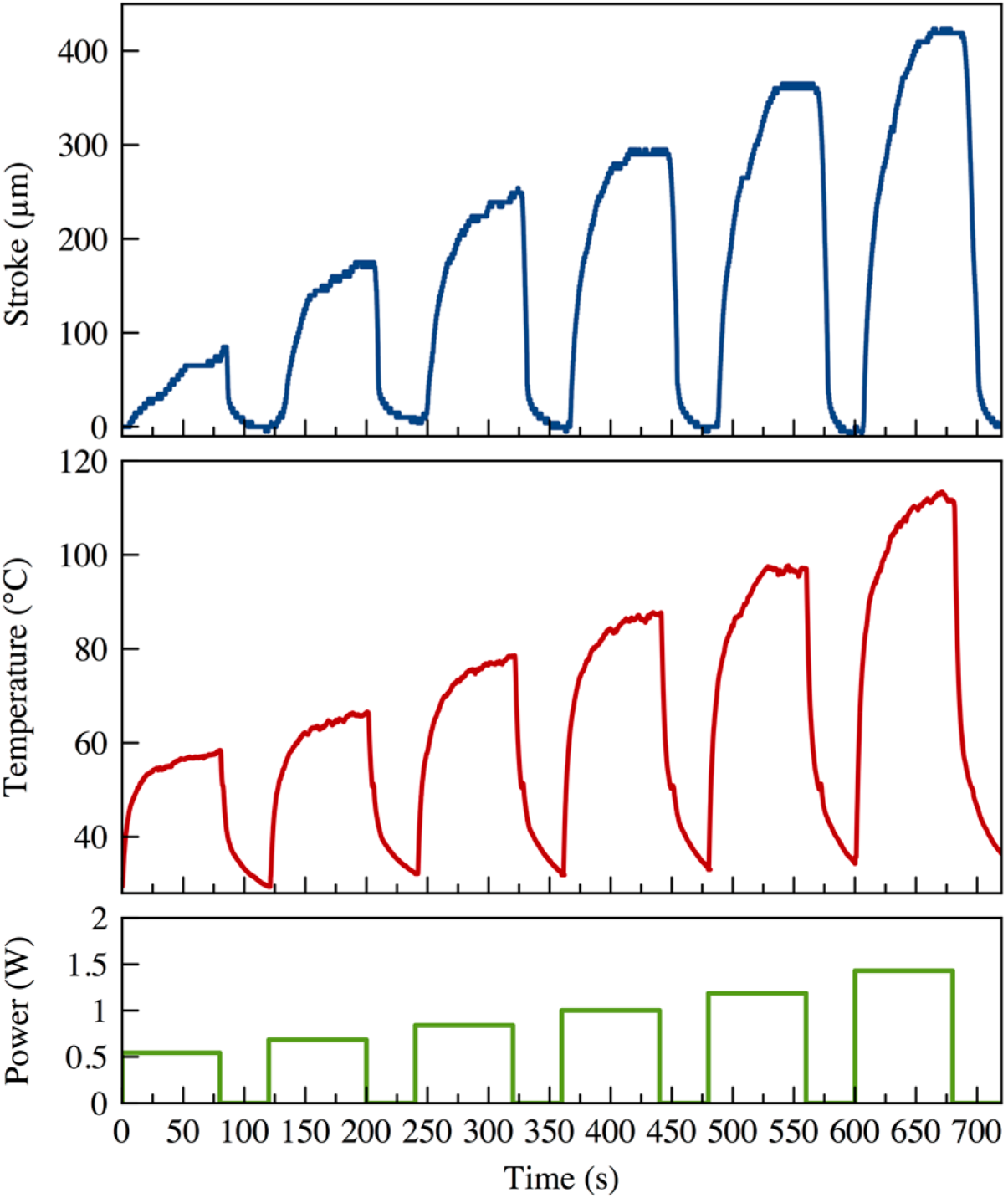
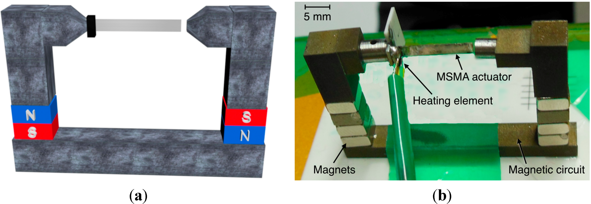
3.2.3. Thermal Linear Actuators

3.3. Bidirectional Magnetostatic and Thermoelastic Actuation
3.3.1. Operation Principle
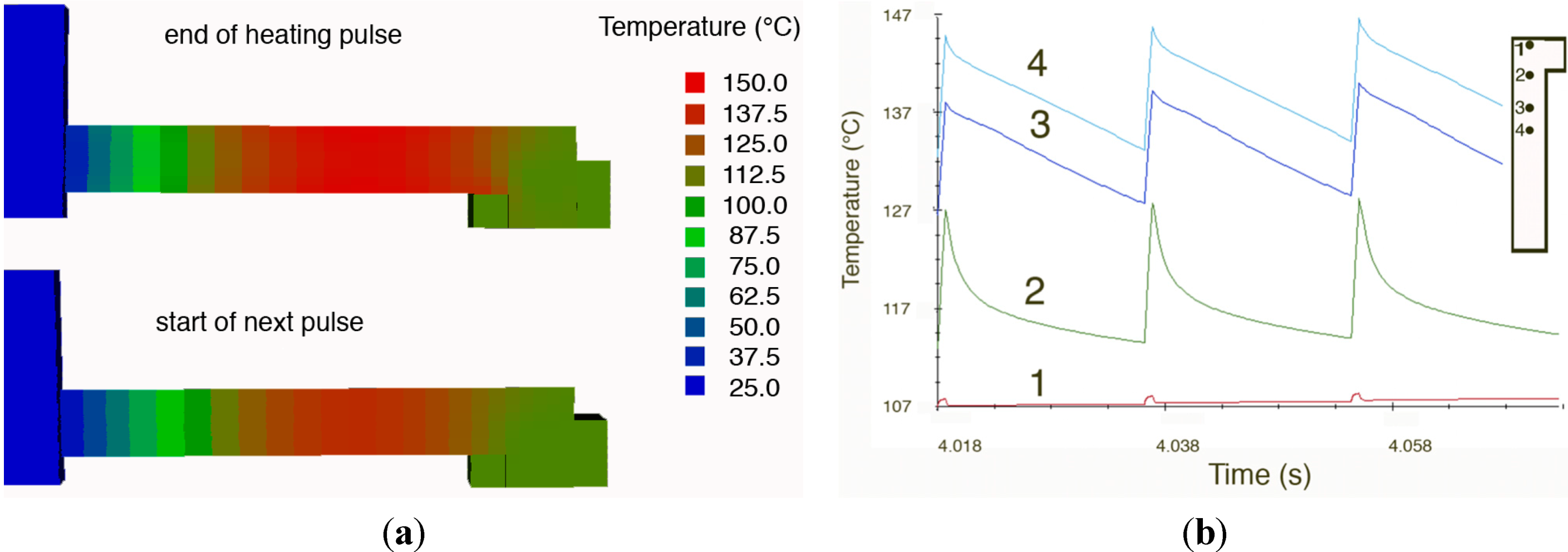
3.3.2. Simulation Model

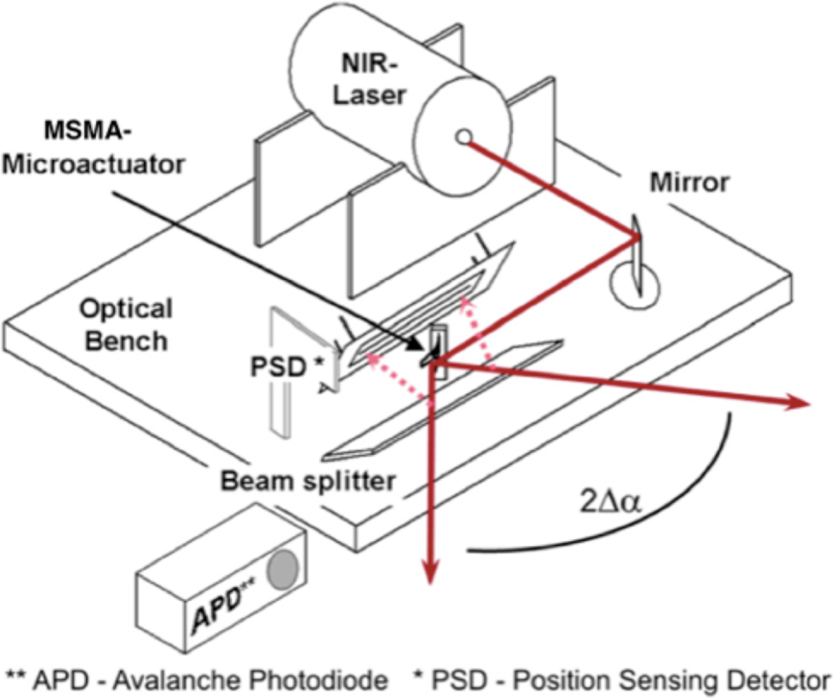
3.3.3. Optical Microscanners


3.4. Thermomagnetic Actuation
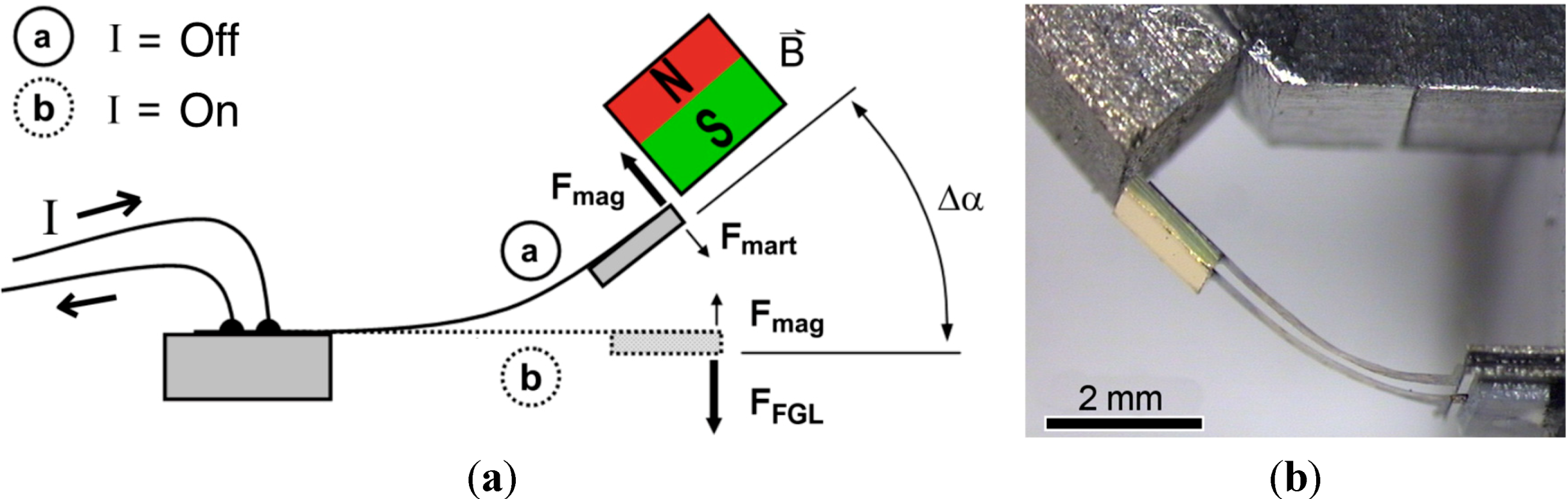
3.4.1. Operation Principle
3.4.2. Thermomagnetic Microswitches
3.5. Magnetic Stray-Field Actuation
4. Conclusions
Acknowledgments
Author Contributions
Conflicts of Interest
References
- Webster, P.J.; Ziebeck, K.R.A. Heusler alloys. In Alloys and Compounds of d-Elements with Main Group Elements. Part 2. Landolt-Börnstein—Group III Condensed Matter; Springer-Verlag: Berlin, Germany, 1988; pp. 75–79. [Google Scholar]
- Kohl, M.; Reddy, Y.S.; Khelfaoui, F.; Krevet, B.; Backen, A.; Fähler, S.; Eichhorn, T.; Jakob, G.; Mecklenburg, A. Recent progress in FSMA microactuator developments. Mater. Sci. Forum 2010, 635, 145–154. [Google Scholar]
- Bhattacharya, K.; James, R.D. The material is the machine. Science 2005, 307, 53–54. [Google Scholar] [CrossRef]
- Ullakko, K.; Huang, J.K.; Kantner, C. Large magnetic-field-induced strains in Ni2MnGa single crystals. Appl. Phys. Lett. 1996, 69, 1966–1968. [Google Scholar] [CrossRef]
- Müllner, P.; Chernenko, V.A.; Kostorz, G. Stress-induced twin rearrangement resulting in change of magnetization in a Ni–Mn–Ga ferromagnetic martensite. Scr. Mater. 2003, 49, 129–133. [Google Scholar] [CrossRef]
- Mañosa, L.; González-Alonso, D.; Planes, A.; Bonnot, E.; Barrio, M.; Tamarit, J.L.; Aksoy, S.; Acet, M. Giant solid-state barocaloric effect in the Ni–Mn–In magnetic shape-memory alloy. Nat. Mater. 2010, 9, 478–481. [Google Scholar] [CrossRef] [Green Version]
- Planes, A.; Mañosa, L.; Acet, M. Magnetocaloric effect and its relation to shape-memory properties in ferromagnetic heusler alloys. J. Phys. Condens. Matter 2009, 21. [Google Scholar] [CrossRef]
- Chernenko, V.A.; Ohtsuka, M.; Kohl, M.; Khovailo, V.V.; Takagi, T. Transformation behavior of Ni–Mn–Ga thin films. Smart Mater. Struct. 2005, 14, S245–S252. [Google Scholar] [CrossRef]
- Khelfaoui, F.; Kohl, M.; Szabo, V.; Mecklenburg, A.; Schneider, R. Development of single crystalline Ni–Mn–Ga foil microactuators. In International Conference on Martensitic Transformations (ICOMAT) 2008; Olsen, G.B., Lieberman, D.S., Saxena, A., Eds.; John Wiley and Sons: Hoboken, NJ, USA, 2013; pp. 215–222. [Google Scholar]
- Heczko, O.; Soroka, A.; Hannula, S.P. Magnetic shape memory effect in thin foils. Appl. Phys. Lett. 2008, 93. [Google Scholar] [CrossRef]
- Dong, J.W.; Chen, L.C.; Xie, J.Q.; Muller, T.; Carr, D.M.; Palmstrøm, C.J.; McKernan, S.; Pan, Q.; James, R.D. Epitaxial growth of ferromagnetic Ni2MnGa on GaAs (001) using NiGa interlayers. J. Appl. Phys. 2000, 88, 7357–7359. [Google Scholar] [CrossRef]
- Thomas, M.; Heczko, O.; Buschbeck, J.; Rößler, U.K.; McCord, J.; Scheerbaum, N.; Schultz, L.; Fähler, S. Magnetically induced reorientation of martensite variants in constrained epitaxial Ni–Mn–Ga films grown on MgO (001). New J. Phys. 2008, 10. [Google Scholar] [CrossRef]
- Jakob, G.; Elmers, H.J. Epitaxial films of the magnetic shape memory material. J. Magn. Magn. Mater. 2007, 310, 2779–2781. [Google Scholar] [CrossRef]
- Backen, A.; Yeduru, S.R.; Diestel, A.; Schultz, L.; Kohl, M.; Fähler, S. Epitaxial Ni–Mn–Ga Films for Magnetic Shape Memory Alloy Microactuators. Adv. Eng. Mater. 2012, 14, 696–709. [Google Scholar] [CrossRef]
- Chernenko, V.A. Compositional instability of beta-phase in Ni–Mn–Ga alloys. Scr. Mater. 1999, 40, 523–527. [Google Scholar] [CrossRef]
- Lanska, N.; Soderberg, O.; Sozinov, A.; Ge, Y.; Ullakko, K.; Lindroos, V.K. Composition and temperature dependence of the crystal structure of Ni–Mn–Ga alloys. J. Appl. Phys. 2004, 95, 8074–8078. [Google Scholar] [CrossRef]
- Murray, S.J.; Marioni, M.A.; Kukla, A.M.; Robinson, J.; Handley, R.C.O.; Allen, S.M. Large field induced strain in single crystalline Ni–Mn–Ga ferromagnetic shape memory alloy. J. Appl. Phys. 2000, 87, 5774–5776. [Google Scholar] [CrossRef]
- Ohtsuka, M.; Itagaki, K. Effect of heat treatment on properties of Ni–Mn–Ga films prepared by a sputtering method. Int. J. Appl. Electromagn. Mech. 2000, 12, 49–59. [Google Scholar]
- Castaño, F.J.; Nelson-Cheeseman, B.; O’Handley, R.C.; Ross, C.A.; Redondo, C.; Castaño, F. Structure and thermomagnetic properties of polycrystalline Ni–Mn–Ga thin films. J. Appl. Phys. 2003, 93, 8492–8494. [Google Scholar]
- Hakola, A.; Heczko, O.; Jaakola, A.; Kajava, T.; Ullakko, K. Ni–Mn–Ga films on Si, GaAs and Ni–Mn–Ga single crystals by pulsed laser deposition. Appl. Surf. Sci. 2004, 238, 155–158. [Google Scholar] [CrossRef]
- Ohtsuka, M.; Konno, Y.; Matsumoto, M.; Takagi, T.; Itagaki, K. Magnetic-field induced two-way shape memory effect of ferromagnetic Ni2MnGa sputtered films. Mater. Trans. 2006, 47, 625–630. [Google Scholar] [CrossRef]
- Besseghini, S.; Gambardella, A.; Chernenko, V.A.; Hagler, M.; Pohl, C.; Muellner, P.M.; Ohtsuka, M.; Doyle, S. Transformation behavior of Ni–Mn–Ga/Si(100) thin film composites with different film thicknesses. Eur. Phys. J. Spec. Top. 2008, 158, 179–185. [Google Scholar] [CrossRef]
- Chernenko, V.A.; Lopez Anton, R.; Barandiaran, J.M.; Orue, I.; Besseghini, S.; Ohtsuka, M.; Gambardella, A. MFM Domain Imaging of Textured Ni–Mn–Ga/MgO(100) Thin Films. IEEE Trans. Magn. 2008, 44, 3040–3043. [Google Scholar] [CrossRef]
- Golub, V.; Reddy, K.M.; Chernenko, V.; Muellner, P.; Punnoose, A.; Ohtsuka, M. Ferromagnetic resonance properties and anisotropy of Ni–Mn–Ga thin films of different thicknesses deposited on Si substrate. J. Appl. Phys. 2009, 105. [Google Scholar] [CrossRef]
- Dong, J.W.; Xie, J.Q.; Lu, J.; Adelmann, C.; Palmstrøm, C.J.; Cui, J.; Pan, Q.; Shield, T.W.; James, R.D.; McKernan, S. Shape memory and ferromagnetic shape memory effects in single-crystal Ni2MnGa thin films. J. Appl. Phys. 2004, 95, 2593–2600. [Google Scholar]
- Zhang, Y.; Hughes, R.A.; Britten, J.F.; Gong, W.; Preston, J.S.; Botton, G.A.; Niewczas, M. Epitaxial Ni–Mn–Ga films derived through high temperature in situ depositions. Smart Mater. Struct. 2009, 18. [Google Scholar] [CrossRef]
- Tillier, J.; Bourgault, D.; Odier, P.; Ortega, L.; Pairis, S.; Fruchart, O.; Caillault, N.; Carbone, L. Tuning macro-twinned domain sizes and the b-variants content of the adaptive 14-modulated martensite in epitaxial Ni–Mn–Ga films by co-sputtering. Acta Mater. 2011, 59, 75–81. [Google Scholar] [CrossRef]
- Backen, A.; Yeduru, S.R.; Kohl, M.; Baunack, S.; Diestel, A.; Holzapfel, B.; Schultz, L.; Fähler, S. Comparing properties of substrate-constrained and freestanding epitaxial Ni–Mn–Ga films. Acta Mater. 2010, 58, 3415–3421. [Google Scholar] [CrossRef]
- Yeduru, S.R.; Backen, A.; Kübel, C.; Wang, D.; Scherer, T.; Fähler, S.; Schultz, L.; Kohl, M. Microstructure of free-standing epitaxial Ni–Mn–Ga films before and after variant reorientation. Scr. Mater. 2012, 66, 566–569. [Google Scholar] [CrossRef]
- Grund, T.; Guerre, R.; Despont, M.; Kohl, M. Transfer bonding technology for batch fabrication of SMA microactuators. Eur. Phys. J. Spec. Top. 2008, 158, 237–242. [Google Scholar] [CrossRef]
- Grund, T.; Cuntz, T.; Kohl, M. Batch fabrication of polymer microsystems with shape memory microactuators. In Proceedings of IEEE 21st International Conference on Micro Electro Mechanical Systems, Tucson, AZ, USA, 13–17 January 2008; pp. 423–426.
- Barth, J.; Megnin, C.; Kohl, M. A bistable shape memory alloy microvalve with magnetostatic latches. J. Microelectromech. Syst. 2012, 21, 76–84. [Google Scholar] [CrossRef]
- Megnin, C.; Kohl, M. Shape memory alloy microvalves for a fluidic control system. J. Micromech. Microeng. 2014, 24. [Google Scholar] [CrossRef]
- Pinneker, V.; Gueltig, M.; Sozinov, A.; Kohl, M. Single phase boundary actuation of a ferromagnetic shape memory foil. Acta Mater. 2014, 64, 179–187. [Google Scholar] [CrossRef]
- Kohl, M.; Brugger, D.; Ohtsuka, M.; Takagi, T. A novel actuation mechanism on the basis of ferromagnetic SMA thin films. Sens. Actuators A 2004, 114, 445–450. [Google Scholar] [CrossRef]
- Gueltig, M.; Ossmer, H.; Ohtsuka, M.; Miki, H.; Tsuchiya, K.; Takagi, T.; Kohl, M. High frequency thermal energy harvesting using magnetic shape memory films. Adv. Energy Mater. 2014. [Google Scholar] [CrossRef]
- Thomas, M.; Heczko, O.; Buschbeck, J.; Lai, Y.W.; McCord, J.; Kaufmann, S.; Schultz, L.; Faehler, S. Stray-field-induced actuation of free-standing magnetic shape-memory films. Adv. Mater. 2009, 21, 3708–3711. [Google Scholar]
- Heczko, O. Magnetic shape memory effect and magnetization reversal. J. Magn. Magn. Mater. 2005, 290, 787–794. [Google Scholar]
- Straka, L.; Hanninen, H.; Heczko, O. Temperature dependence of single twin boundary motion in Ni–Mn–Ga martensite. Appl. Phys. Lett. 2011, 98. [Google Scholar] [CrossRef]
- Suorsa, I.; Tellinen, J.; Pagounis, E.; Aaltio, I.; Ullakko, K. Applications of magnetic shape memory actuators. In Proceedings of Actuator 2002, Bremen, Germany, 10–12 June 2002; pp. 158–161.
- Tellinen, J.; Suorsa, I.; Jääskeläinen, A.; Aaltio, I. Basic properties of magnetic shape memory actuators. In Proceedings of Actuator 2002, Bremen, Germany, 10–12 June 2002; pp. 10–12.
- Faran, E.; Shilo, D. The kinetic relation for twin wall motion in NiMnGa. J. Mech. Phys. Solids 2011, 59, 975–987. [Google Scholar] [CrossRef]
- Sozinov, A.; Lanska, N.; Soroka, A.; Zou, W. 12% magnetic field-induced strain in Ni–Mn–Ga-based non-modulated martensite. Appl. Phys. Lett. 2013, 102. [Google Scholar] [CrossRef]
- Murray, S.J.; Marioni, M.; Allen, S.M.; O’Handley, R.C.; Lograsso, T.A. 6% magnetic-field-induced strain by twin-boundary motion in ferromagnetic Ni–Mn–Ga. Appl. Phys. Lett. 2000, 77, 886–888. [Google Scholar] [CrossRef]
- Kohl, M.; Krevet, B.; Yeduru, S.R.; Ezer, Y.; Sozinov, A. A novel foil actuator using the magnetic shape memory effect. Smart Mater. Struct. 2011, 20. [Google Scholar] [CrossRef]
- James, R.D.; Wuttig, M. Magnetostriction of martensite. Philos. Mag. A 1998, 77, 1273–1299. [Google Scholar] [CrossRef]
- Likhachev, A.A.; Ullakko, K. Quantitative model of large magnetostrain effect in ferromagnetic shape memory alloys. Eur. Phys. J. B 2000, 14, 263–267. [Google Scholar] [CrossRef]
- Kiefer, B.; Lagoudas, D.C. Modeling the coupled strain and magnetization response of magnetic shape memory alloys under magnetomechanical loading. J. Intell. Mater. Syst. Struct. 2009, 20, 143–170. [Google Scholar]
- Kohl, M.; Krevet, B. 3D simulation of a shape memory microactuator. Mater. Trans. 2002, 43, 1030–1036. [Google Scholar] [CrossRef]
- O’Handley, R.C. Model for strain and magnetization in magnetic shape-memory alloys. J. Appl. Phys. 1998, 83, 3263–3270. [Google Scholar] [CrossRef]
- Hirsinger, L.; Lexcellent, C. Internal variable model for magneto-mechanical behaviour of ferromagnetic shape memory alloys Ni–Mn–Ga. J. Phys. IV France 2003, 112, 977–980. [Google Scholar] [CrossRef]
- Lee, K.L.; Seelecke, S. A model for ferromagnetic shape memory thin film actuators. Smart Struct. Mater. 2005, 5757, 302–313. [Google Scholar]
- Krevet, B.; Kohl, M. FEM simulation of a Ni–Mn–Ga film bridge actuator. Physics Procedia 2010, 10, 154–161. [Google Scholar] [CrossRef]
- Krevet, B.; Pinneker, V.; Kohl, M. A magnetic shape memory foil actuator loaded by a spring. Smart Mater. Struct. 2012, 21. [Google Scholar] [CrossRef]
- Krevet, B.; Kohl, M.; Morrison, P.; Seelecke, S. Magnetization- and strain-dependent free energy model for FEM simulation of magnetic shape memory alloys. Eur. Phys. J. Spec. Top. 2008, 158, 205–211. [Google Scholar] [CrossRef]
- Krevet, B.; Kohl, M. Modeling and FEM simulation of shape memory microactuators. Mater. Sci. Forum 2008, 583, 229–256. [Google Scholar] [CrossRef]
- Krevet, B.; Kohl, M. Thermodynamic modelling of ferromagnetic shape memory actuators. Mater. Sci. Forum 2009, 635, 175–180. [Google Scholar] [CrossRef]
- Pinneker, V.; Krevet, B.; Ezer, Y.; Sozinov, A.; Kohl, M. A Ni–Mn–Ga foil actuator based on the magnetic shape memory effect. In Proceedings of Actuator 2012, Bremen, Germany, 18–20 June 2012; pp. 332–335.
- Niskanen, A.J.; Soroka, A. Proportional control and self-sensing in a magnetic shape memory (MSM) alloy actuator. In Proceedings of Actuator 2012, Bremen, Germany, 18–20 June 2012; pp. 276–278.
- Srivastava, V.K.; Chatterjee, R.; O’Handley, R.C. Effect of twin boundaries on electrical transport in a Ni–Mn–Ga single crystal. Appl. Phys. Lett. 2006, 89. [Google Scholar] [CrossRef]
- Zeng, M.; Cai, M.Q.; Or, S.W.; Chan, H.L.W. Anisotropy of the electrical transport properties in a Ni2MnGa single crystal: Experiment and theory. J. Appl. Phys. 2010, 107. [Google Scholar] [CrossRef]
- Suorsa, I.; Pagounis, E.; Ullakko, K. Position dependent inductance based on magnetic shape memory materials. Sens. Actuators A 2005, 121, 136–141. [Google Scholar] [CrossRef]
- Krevet, B.; Kohl, M.; Brugger, D. Coupled simulation of the thermo-magneto-mechanical properties of a Ni–Mn–Ga actuator. Int. J. Appl. Electromagn. Mech. 2006, 23, 125–131. [Google Scholar]
- Krevet, B.; Kohl, M. Finite element simulation of SMA microactuators with large deflection. J. Phys. IV France 2004, 115, 365–373. [Google Scholar] [CrossRef]
- Brugger, D.; Kohl, M.; Hollenbach, U.; Kapp, A.; Stiller, C. Ferromagnetic shape memory microscanner system for automotive applications. Int. J. Appl. Electromagn. Mech. 2006, 23, 107–112. [Google Scholar]
- Kainuma, R.; Imano, Y.; Ito, W.; Morito, H.; Sutou, Y.; Oikawa, K.; Fujita, A.; Ishida, K.; Okamoto, S.; Kitakami, O.; et al. Magnetic-field-induced shape recovery by reverse phase transformation. Nature 2006, 439, 957–960. [Google Scholar]
- Niemann, R.; Heczko, O.; Schultz, L.; Fähler, S. Metamagnetic transitions and magnetocaloric effect in epitaxial Ni–Co–Mn–In films. Appl. Phys. Lett. 2010, 97. [Google Scholar] [CrossRef]
- Srivastava, V.; Chen, X.; James, R.D. Hysteresis and unusual magnetic properties in the singular Heusler alloy Ni45Co5Mn40Sn10. Appl. Phys. Lett. 2010, 97. [Google Scholar] [CrossRef]
- Zarnetta, R.; Takahashi, R.; Young, M.L.; Savan, A.; Furuya, Y.; Thienhaus, S.; Maaß, B.; Rahim, M.; Frenzel, J.; Brunken, H.; et al. Identification of quaternary shape memory alloys with near-zero thermal hysteresis and unprecedented functional stability. Adv. Funct. Mater. 2010, 20, 1917–1923. [Google Scholar]
- Gueltig, M.; Ossmer, H.; Ohtsuka, M.; Miki, H.; Tsuchiya, K.; Takagi, T.; Kohl, M. Thermomagnetic actuation by low hysteresis metamagnetic Ni–Co–Mn–In films. Mater. Today. submitted for publication.
© 2014 by the authors; licensee MDPI, Basel, Switzerland. This article is an open access article distributed under the terms and conditions of the Creative Commons Attribution license (http://creativecommons.org/licenses/by/4.0/).
Share and Cite
Kohl, M.; Gueltig, M.; Pinneker, V.; Yin, R.; Wendler, F.; Krevet, B. Magnetic Shape Memory Microactuators. Micromachines 2014, 5, 1135-1160. https://doi.org/10.3390/mi5041135
Kohl M, Gueltig M, Pinneker V, Yin R, Wendler F, Krevet B. Magnetic Shape Memory Microactuators. Micromachines. 2014; 5(4):1135-1160. https://doi.org/10.3390/mi5041135
Chicago/Turabian StyleKohl, Manfred, Marcel Gueltig, Viktor Pinneker, Ruizhi Yin, Frank Wendler, and Berthold Krevet. 2014. "Magnetic Shape Memory Microactuators" Micromachines 5, no. 4: 1135-1160. https://doi.org/10.3390/mi5041135