Article

Stress-Free Bonding Technology with Pyrex for Highly Integrated 3D Fluidic Microsystems

Design of Microsystems, Department of Microsystems Engineering (IMTEK), University of Freiburg, Georges-Koehler-Allee 103, 79110 Freiburg, Germany
*
Author to whom correspondence should be addressed.
Micromachines 2014, 5(3), 783-796; https://doi.org/10.3390/mi5030783
Submission received: 4 August 2014 / Revised: 5 September 2014 / Accepted: 11 September 2014 / Published: 23 September 2014
(This article belongs to the Special Issue Micropumps: Design, Fabrication and Applications)

Abstract

:
In this article, a novel Pyrex reflow bonding technology is introduced which bonds two functional units made of silicon via a Pyrex reflow bonding process. The practical application demonstrated here is a precision dosing system that uses a mechanically actuated membrane micropump which includes passive membranes for fluid metering. To enable proper functioning after full integration, a technique for device assembly must be established which does not introduce additional stress into the system, but fulfills all other requirements, like pressure tolerance and chemical stability. This is achieved with a stress-free thermal bonding principle to bond Pyrex to silicon in a five-layer stack: after alignment, the silicon-Pyrex-silicon stack is heated to 730 °C. Above the glass transition temperature of 525 °C Pyrex exhibits viscoelastic behavior. This allows the glass layer to come into close mechanical contact with the upper and lower silicon layers. The high temperature and the close contact promotes the formation of a stable and reliable Si-O-Si bond, without introducing mechanical stress into the system, and without deformation upon cooling due to thermal mismatch.

1. Introduction

Fluidic microsystems such as micropumps, microreactors or micromixers are designed to allow either chemical or biological reactions at the microscale under variable pressure, flow rate or temperature [1,2]. In a lab-on-chip system, these reactions happen in a sequence of different process stages, e.g., by sequential mixing, measuring and dispensing, which are performed by different functional units integrated into the microreactor system. One of these functional units may be a micropump, which itself includes several integrated components such as active or passive valves, actuated membranes, or pump chambers. Therefore, the need for an integration of different functional units is evident for many types of complex microfluidic systems. In order to obtain highly integrated systems with different requirements for mechanical stability, functionality, chemical resistance, and biological compatibility, new 3D fluidic assembly techniques for functional units made from different materials must be developed. Key requirements are the use of chemically and mechanically stable materials at interfaces [3].
In this work, a silicon micropump and a silicon dosing unit are bonded together onto a common Pyrex wafer carrying fluidic vias which connect both units. In the same bonding step, Pyrex tubes, which can be used as a fluidic connection to external fluid handling equipment, are also bonded to the system. The silicon-based systems consist of two bonded wafers each and include thin membranes. After assembly, a five-layer stack is formed, whose functionality is demonstrated as a proof-of-concept for this bonding technology.

2. Fundamentals of the Reflow Fusion Bond
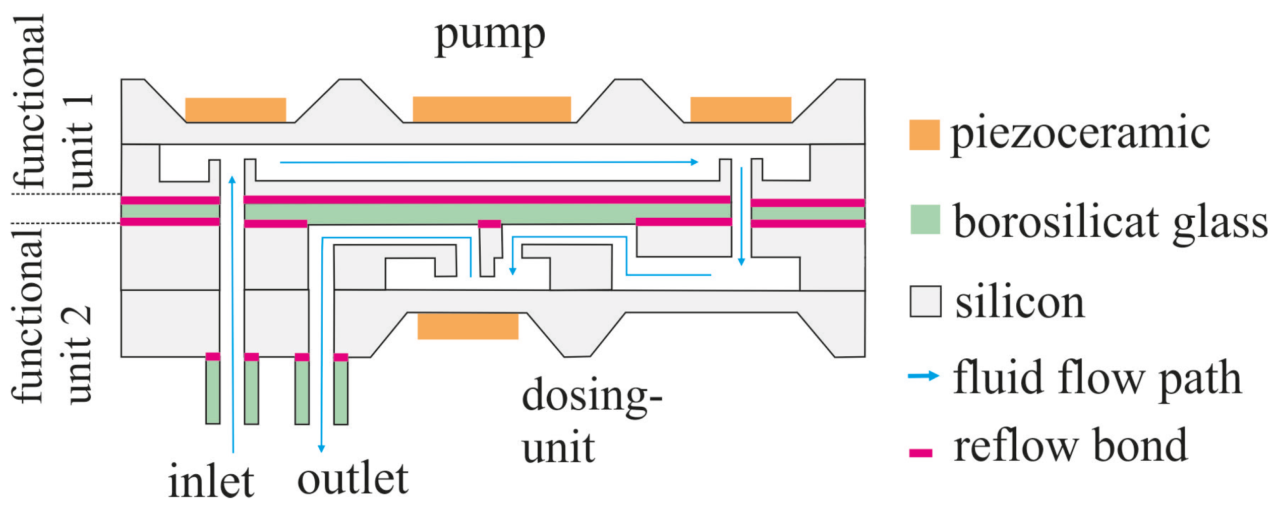
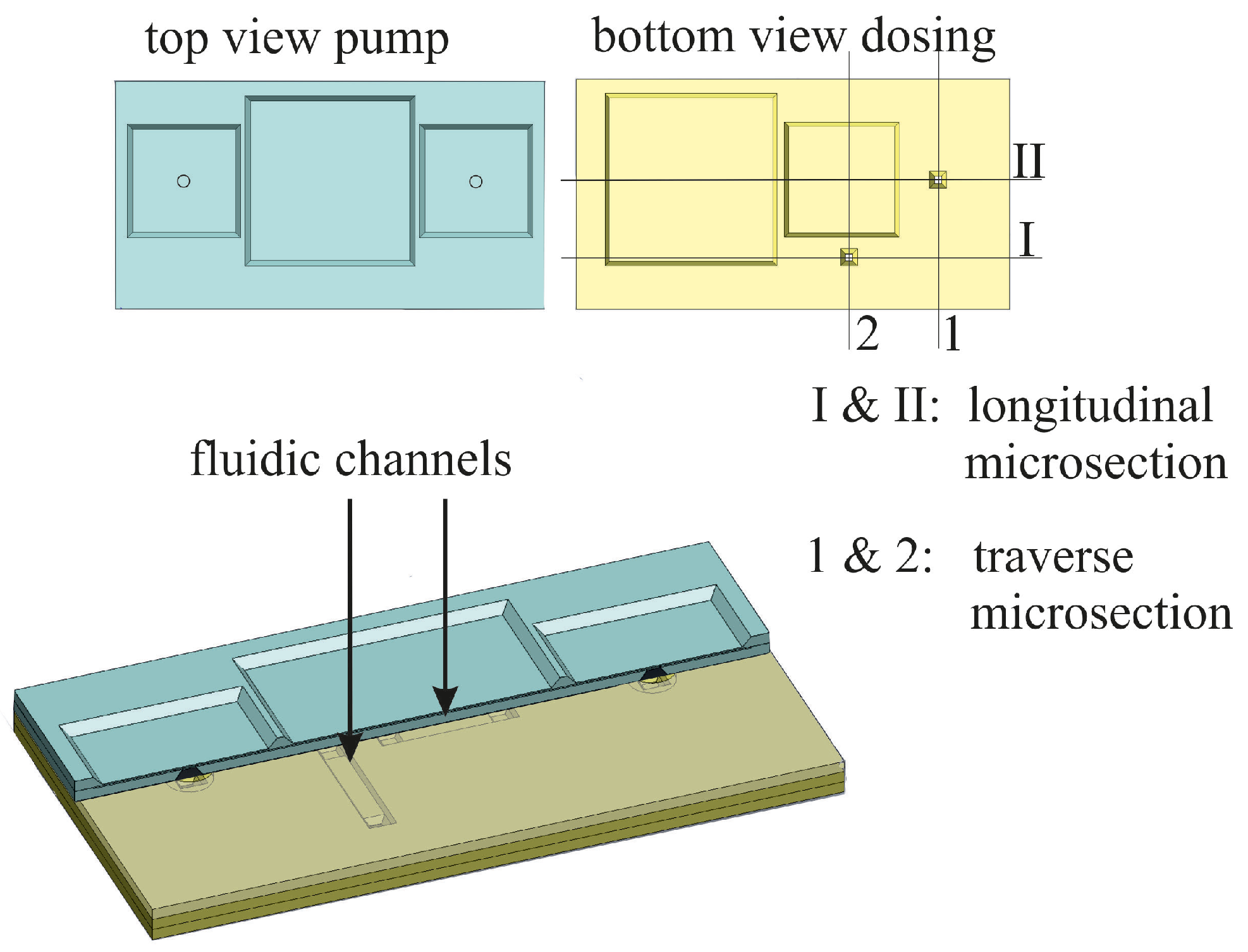
In this section the physical and chemical basics of reflow fusion bonding will be described. A reflow fusion bond of two silicon-based fluidic systems using a structured borosilicate glass chip will be shown. In addition, tubes made of borosilicate glass used as fluidic interconnects to external fluid handling equipment are bonded to this fluidic system in the same bonding step.

2.1. Fluidic System

The fluidic system consists of two primary parts. The first is a piezoelectrically driven silicon micropump [4], which consists of two structured silicon chips, see Figure 1. The second part is a dosing control unit, which also consists of two structured silicon wafers. Both functional units include thin silicon membranes, which are highly vulnerable to mechanical stress. The whole system is bonded together using a structured borosilicate glass (Pyrex, Corning, NY, USA) chip, and connected to external equipment via borosilicate glass tubes, as seen in Figure 1. The bonding of the two functional units as well as that of the fluidic interconnects, can be performed in one process step, which is a significant advantage over alternative common bonding techniques like silicon-fusion or anodic bonding. In addition, this integration process overcomes several problems related to establishing fluidic interconnections via techniques such as soldering or gluing; these methods can produce clogged channels and may lack the necessary chemical resistivity [5]. In addition to the advantages of the single step process, this bonding technique is designed so that no external bonding pressure is needed. The absence of bonding forces differentiates this method differs from others such as anodic bonding and silicon fusion bonding. During anodic bonding, for example, strong electrostatic attraction generates an applied bonding force [6,7], while a silicon fusion bond is initiated by an external pressure applied directly by the bonding chucks [8]. These induced stresses can be a problem for multilayer stacks. The bow and the warp of the different layers may vary widely, which leads to additional stresses, when the surfaces of the layers are forced into close contact [8].
Figure 1. Schematic drawing of the 3D fluidic system described in this work. To present the potential of the presented reflow bonding technology, we used a complex 3D fluidic system with channels, vias, membranes, and fluidic connections to external fluid handling equipment.
Micromachines 05 00783 g001

2.2. Fundamentals of the Pyrex Bonding Technology

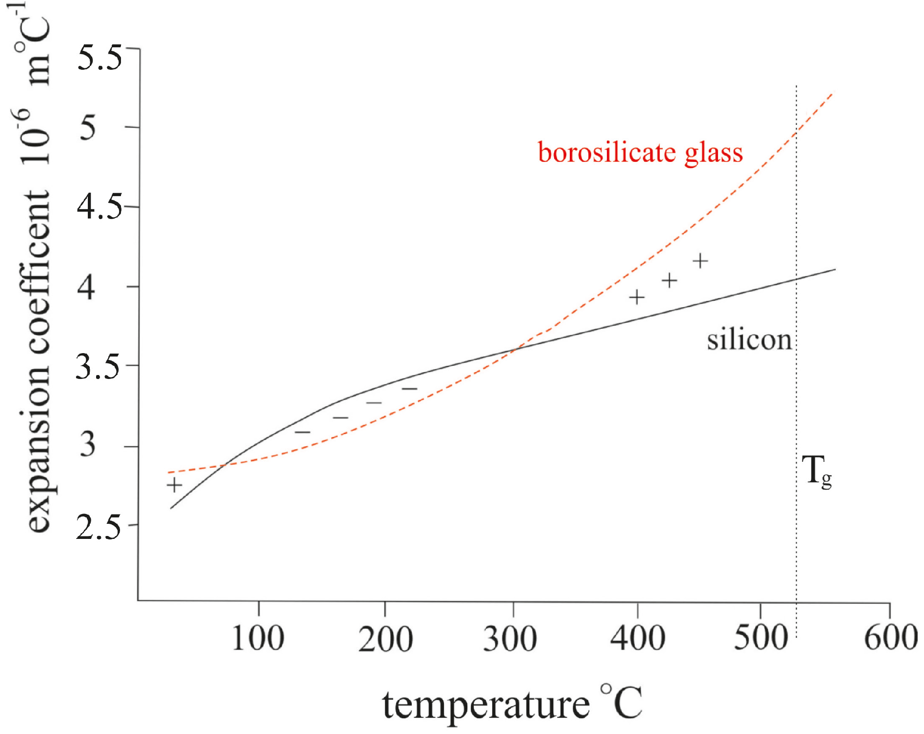
2.2.1. Components of Borosilicate Glass

Borosilicate glass is a very useful material for microfluidic system because of its chemical resistance. Moreover, it is approved for pharmaceutical applications, like packaging or transport [9].
These characteristics are not important for the performance of the bonding process that we present, but do demonstrate a wide variety of applications. The chemical composition of the glass can be seen in Table 1 [9].
Table 1. Chemical composition of Borosilicate glass (Pyrex) [9].
Weight %Compound
81SiO2
13Bi2O3
4Na2O + K2O
2Al2O3

2.2.2. Physical and Chemical Principles of the Bond

Pyrex-silicon bonds fundamentally on the Si-O-Si covalent bonds at the interface between the two substrates. This bond is described in several scientific reviews, including [8,10]. The new idea of a reflow bond process with Pyrex is described by Fazal et al. in [11]. By heating up Pyrex above the glass transition temperature, it becomes viscoelastic and is able to flow. For that reason, Pyrex can fill any irregularities on the silicon substrate and generate Si-O-Si bonds over the entire surface.
An example of a temperature profile for the bonding process can be seen in Figure 2. Four critical steps are emphasized. In the first step, the assembly is heated to a temperature of 200 °C to evaporate residual moisture on the substrate surfaces. Afterwards, the Pyrex is heated up to the bonding temperature, which is 150–250 °C above the glass transition temperature. This temperature is held for several hours, during which Si-O-Si crosslinking takes place. In this temperature range, an unwanted effect called devitrification of the Pyrex occurs. Studies of heat-treated borosilicate glass at and above 660 °C show that crystal growth occurs. This is connected to the diffusion of boron and sodium within the borosilicate framework [12,13]. During cooling, a certain wait time slightly above the glass transition temperature is necessary before cooling further. This wait time guarantees as state where no mechanical stress is present in the borosilicate glass [9,14]. After achieving the stress-free-state, almost no additional stress will be transmitted to the bonded substrates.
The stress relaxation in the Pyrex occurs due to the viscoelastic flow. After the cool-down pause indicated in Figure 2, the assembly is further cooled down to room temperature at a certain rate which is dependent on the thickness of the glass and is given by the data sheet of the supplier [9]. During this cooling step, virtually no stress is built up, because the coefficient of thermal expansion of both materials is almost identical, see Figure 3.
Figure 2. Temperature profile of the reflow bond. Step 1 is a baking step to evaporate moisture from the silicon and glass substrates. Step 2 is the bonding step at a temperature above the glass-transition of the borosilicate glass and Step 3 is a pause slightly above the glass transition temperature to release stress in the borosilicate glass chip. Step 4 is the cool-down to room temperature at a defined rate given by the supplier of the glass [9].
Micromachines 05 00783 g002
Figure 3. Coefficient of thermal expansion of borosilicate glass and silicon. Below the glass transition temperature they are almost identical [12].
Micromachines 05 00783 g003

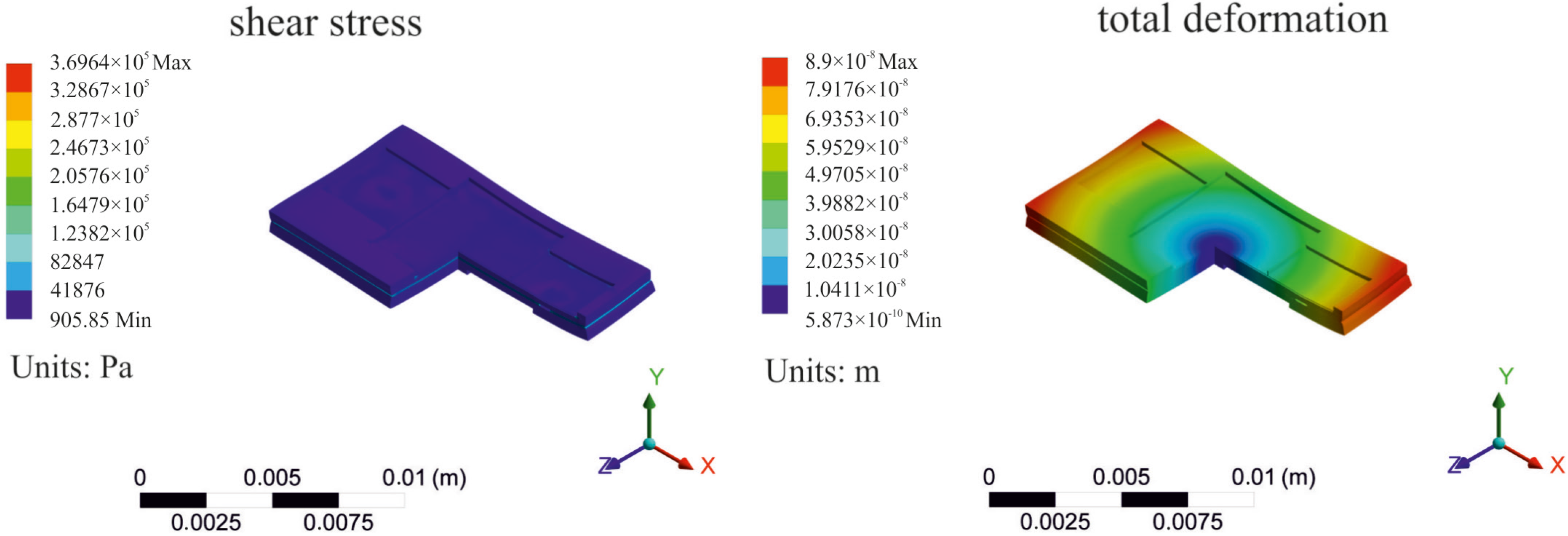
2.3. Simulation of the Bonded Assembly

To measure the stress in a bonded assembly, the curvature of the bonded assembly has to be measured. This technique can be used for asymmetric assemblies. For symmetric or almost symmetric assemblies, the curvature is too small to serve as a measure for stress. The presented system, see Figure 1, is almost symmetric and therefore the stress cannot be measured by curvature. For this reason, we performed an FEM-simulation to simulate the induced shear stress and the total deformation during the heating, bonding and cooling steps. Therefore, a model was set up which includes the membranes and the fluidic channels. The start of the cool down of the simulation is considered as stress free with bonded contacts between the different layers [9]. The boundary conditions were considered as weak springs to model the free motion of the assembly. As expected, the total deformation of the system is almost zero. This relates to the symmetric assembly of the system. The simulated shear stress in the system is concentrated in the glass with a maximum of only 0.37 MPa. Almost no stress is observed in the membrane which is one of the major goals for this bonding technique (Figure 4). The model contains all channels and membranes. After the cooling-process, however, the deformations are small, approximating the behavior of a stress-balanced trimorph structure.
Figure 4. Coupled thermal-mechanical FEM-simulation for calculating the shear stress and the total deformation of the bonded system. As can be seen, no stress occurs in the fragile membranes.
Micromachines 05 00783 g004

3. Preliminary Tests

In this section, the preliminary tests of the two bonding processes, the trimorph Si-Pyrex-Si bond and the borosilicate tube bond, on silicon will be shown. The aim of this test was to find parameters which enable the bonding of the functional units together while simultaneously bonding the Pyrex interconnect tubes.

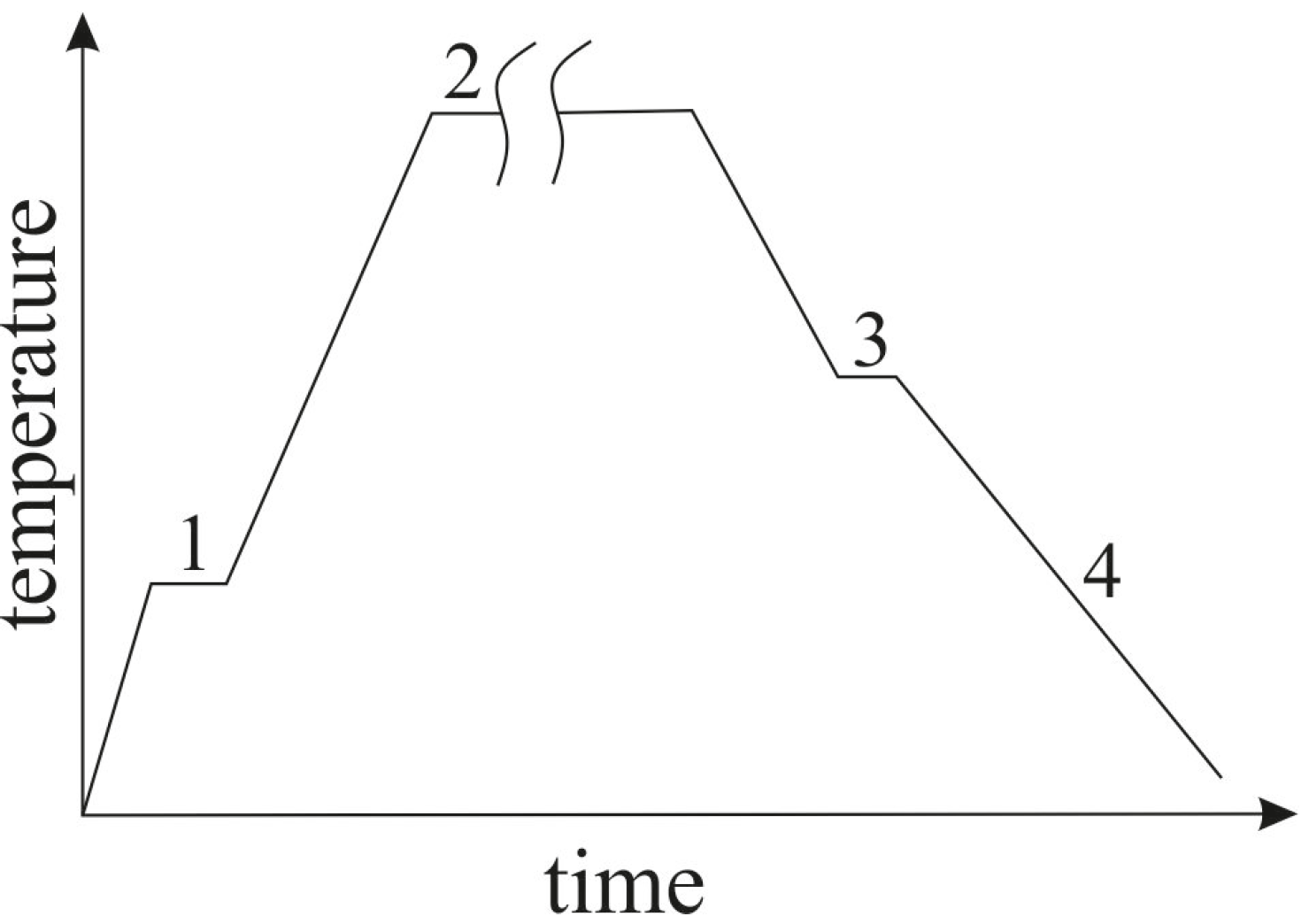
3.1. Fabrication and Experiments

Because we wish in this work to perform bonding of silicon and Pyrex substrates as well as of Pyrex interconnect tubes simultaneously, the more commonly used anodic bonding is not possible. Anodic bonding of the two functional units with a Pyrex interlayer is possible but will not allow an integration of the Pyrex glass tubes in the same step. Additionally, anodic bonding for silicon-Pyrex-silicon stacks requires special techniques that cannot be implemented simply. Bow and warp of the silicon generate additional stresses in such stacks, which is compounded the more layers there are. Structured wafers also yield additional stresses caused by the inhomogeneity of the temperature and the electrostatic fields during the anodic bonding process [14]. In the procedure that we present, the borosilicate-glass is softened and is thus able to overcome the bow and the warp via viscoelestic flow. In order to minimize residual stress in anodically bonded structures, an annealing step at temperatures above 500 °C is recommended [14]. The principles of the Pyrex-tube-to-silicon bond are presented by the group of Fazal et al. [11]. Before the whole system was bonded, preliminary tests of the shear strength of the fusion bonding technique and an optimization of the trimorph Si-Pyrex-Si bond are performed which we now present.

Preparation of the Bonded Components

Both functional units are made of two fusion bonded, structured silicon wafers, see Figure 1. All surfaces of these units contain a thin thermally grown SiO2 layer. Both have a length of 30.2 mm and a width of 16 mm. The Pyrex tubes where supplied by Schott AG. The tubes, that were bonded to the system, were diced to a length of 5 mm, and had an outer diameter of 6 mm (wall thickness 1.5 mm). Because the tubes were diced, the top and bottom surfaces were rough. In order to obtain a fluidic interconnection between the micropump and the dosing unit, the Pyrex wafer must be structured and diced to the same size as the functional units. First, photolithography is performed on a Pyrex wafer to define saw marks and the locations of the feedthrough vias. A special drilling process for glass is performed. After drilling, the feedthroughs successively undergo dicing and cleaning steps with aceton iso-propanol, and finally, a di-water rinse under ultrasonic power to acquire the final structured Pyrex bonding layer. After these preparation steps, the pre-bonding treatment is performed which consists of a cleaning step with a subsequent baking process to evaporate the moisture. The cleaning step will be explained later.

3.2. Preliminary Experiments: Tube on Silicon

To find the best bonding parameters for both reflow bond processes, the trimorph Si-Pyrex-Si bond and the borosilicate tube bond on silicon were analyzed separately. The bonding was performed in a Carbolite GHA 12/750 quartz tube furnace.

3.2.1. Design of Experiments

In order to find the best possible bonding conditions, we set up a design of experiments with the following parameters (Table 2).
Table 2. Parameters for the design of experience.
FactorUnitCondition 1Condition 2
Cleaning step before bondN/APiranha etchPiranha etch and HF
Heating rate (Step 1 to 2)°C/min715
Bonding temperature°C730770
Cool-down wait-time (Step 3)h612
Cleaning is considered to be a critical parameter for almost every bonding process. As described in the literature, organic particles must be removed from the bonding surfaces, which we achieved with the Piranha etch. Treatment with 5% hydrofluoric acid (HF) furthermore aids in the removal of undesired oxide layers. The heating rate was varied in order to identify a minimum necessary heating time, beyond which no further gains are attained, while not impacting the bonding process itself. The cool-down rate was determined by the guidelines of the Schott AG (Mainz, Germany) for stress free cooling of Borosilicate glass. The bonding temperature is considered to be the most important factor, in order to reduce unwanted side effects, like devitrification. In order to minimize these, Pyrex is exposed as short as possible to this temperature. Based on the parameters in Table 2, we prepared a 24-1 fractional experimental design with statistical software JMP from SAS (Böblingen, Germany).

3.2.2. Test Setup

For the characterization of the bond strength, a shear test was performed. After bonding to a dummy substrate, five tubes where sheared with a Dage Series 4000 from Dage Semiconductor GmbH [15]. The setup for the shear experiments was as follows:
  • Speed of the axes is 100 µm/s;
  • Shear height is 100 µm;
  • Load cell is DS 100 Kg.

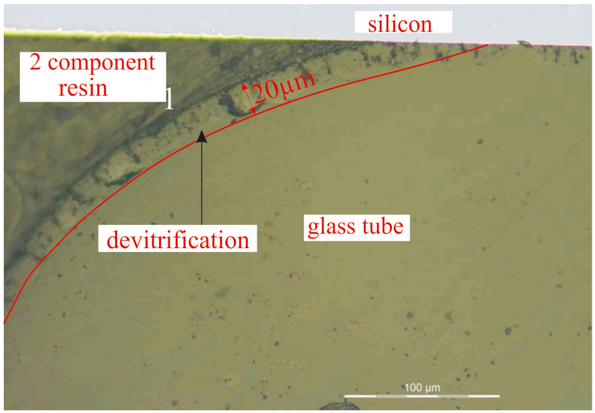
3.2.3. Results for Tube Bonding

For each test in the fractional design of experiments, seven tubes were bonded. Five bonded tubes were used for the shear test and the other two were used for micrograph analyses. It was seen, that the shear strength in all cases increased with bonding temperature. It was also observed that the heating rate and the additional HF cleaning step before the bond did not significantly affect the bonding strength. The experiment shows that a causal relation between bonding time and bonding temperature with the bonding strength exists, as shown in Table 3. The evaluation of the shear test shows that the highest mean shear strength was 13.5 N/mm2 and the lowest 4.68 N/mm2. Some of the results of the shear test are presented in Table 3. As can be seen, bonding strength is highly dependent on the bonding time and temperature. While the bonding shear strength of the tubes, bonded at 730 °C increased with the bonding time, the shear strength decreased with the bonding time at a bonding temperature of 770 °C. This can be explained by two primary effects. Higher temperature improves the flow characteristics of the glass, which enables a better coverage of the glass on the silicon. At the same time, however, the occurrence of devitrification is significantly increased at the higher temperature, which weakens the structure of the glass (Figure 5).
In addition to the shear test, an optical inspection of the cross section was performed. The devitrification can be seen in Figure 5. The depth and the density of the cracks increase with time and temperature.
Table 3. Results of the shear test with variable bonding parameters.
ExperimentConditionsMean shear forceStd. dev.Mean shear strength
Bonding Temperature\Bonding Time\Cleaning(N)(N)(N/mm2)
1730 °C\6 h\Piranha140.670.76.6
2770 °C\12 h\Piranha + HF203.327.69.6
3730 °C\12 h\Piranha163.932.77.7
4770 °C\6 h \Piranha + HF282.931.613.3
5770 °C\6 h\Piranha287.054.913.5
Figure 5. Bonded glass tube on silicon. Devitrification can be seen on the surface. In this region, crack propagation starts during the shear strength test.
Micromachines 05 00783 g005

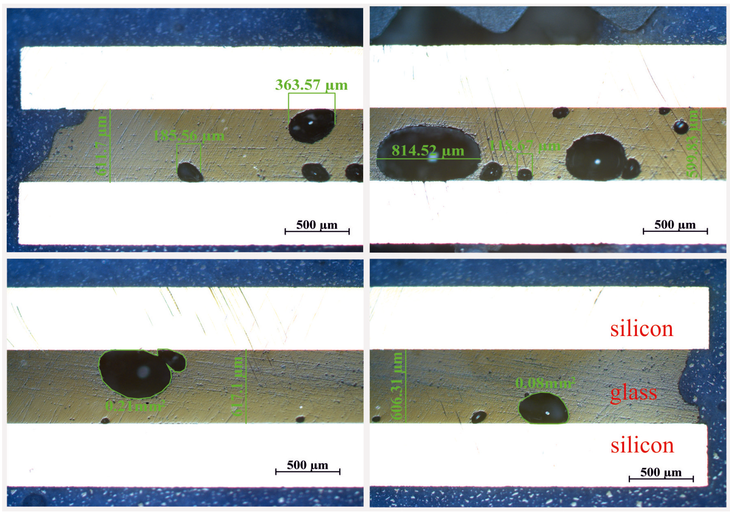
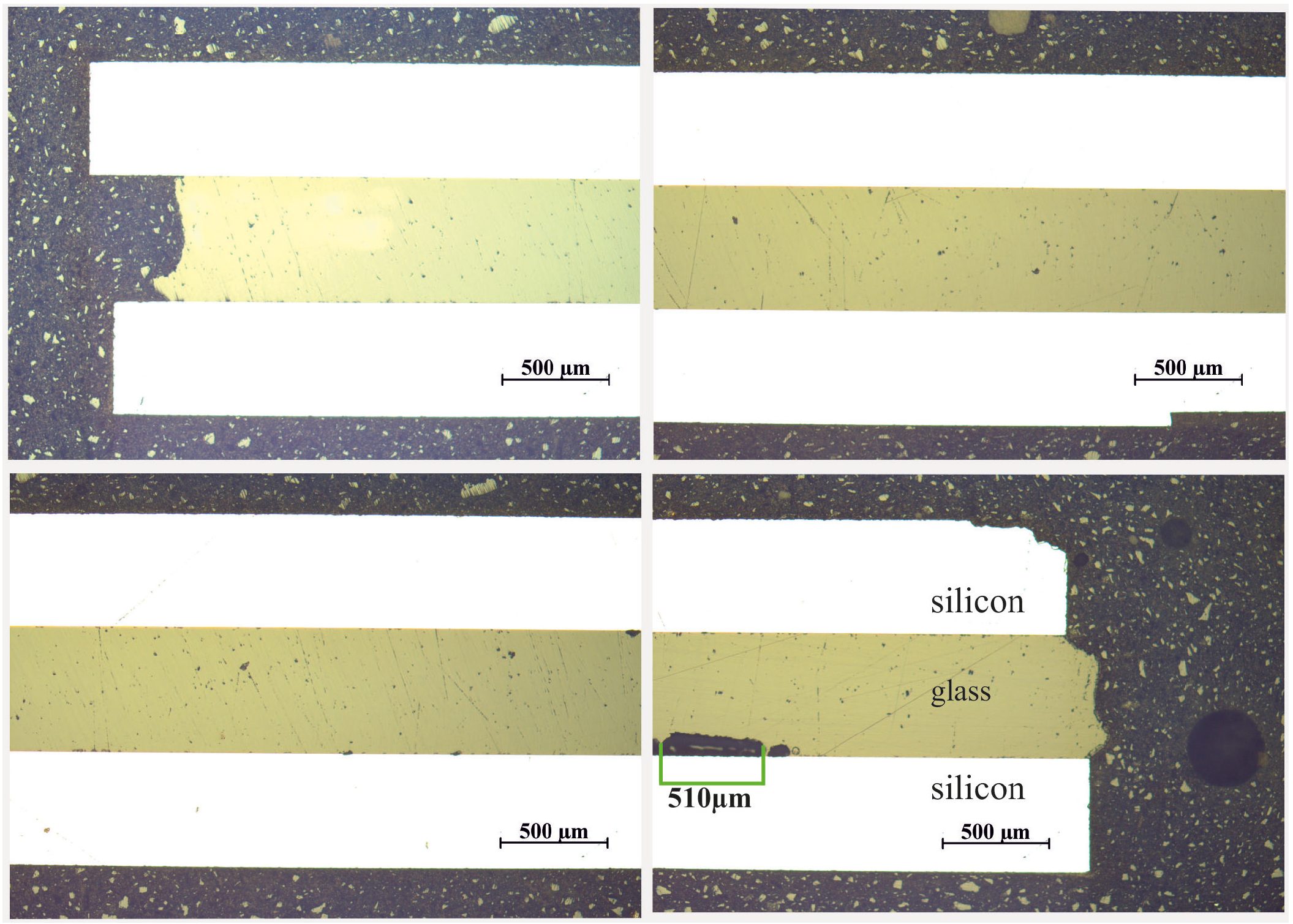
3.3. Preliminary Experiments: Silicon Chips Bonded to a Pyrex Chip

In this section, preliminary tests for the bonding of a silicon-Pyrex-silicon stack are described. In contrast to the bonding of a Pyrex tube on silicon, most of the Pyrex surface here is covered by the silicon chips. This decreases the effect of devitrification [15], but includes the possibility of trapped gases which may form bubbles in the Pyrex. In this section, we describe preliminary tests for finding the best process parameters for bonding without bubbles. The comparison of the different bonding temperatures shows a clear result, see Figure 6, Figure 7 and Figure 8. Both the bubble size and the number of bubbles decrease with temperature.
Figure 6. Bonded silicon-glass-silicon stack. The sequence of the images shows a cross section of a 10 × 10 mm2 chip. Each image shows 2 mm-long segment of the cross section. The bubbles are the result of devitrification and trapped gases. The bonding temperature was set to 770 °C.
Micromachines 05 00783 g006
Figure 7. Bonded silicon-glass-silicon stack. The sequence of the images shows a cross section of a 10 × 10 mm2 chip. The bonding temperature was set to 730 °C.
Micromachines 05 00783 g007
Figure 8. Bonded silicon-glass-silicon stack. The sequence of the images shows a cross section of a 10 × 10 mm2 chip. The bonding temperature was set to 680 °C.
Micromachines 05 00783 g008

3.4. Discussion of the Preliminary Test

In the preliminary test, we observed that temperature and time are the critical parameters for the quality of the reflow bond. The lowest temperature which allows proper bonding conditions differs for both experiments. This can be explained by the different surface topologies. Compared to the surface roughness of the Pyrex wafer, the surface roughness of the diced tubes is significantly higher. Therefore, more softening of the diced surface of the Pyrex tube is required via higher temperatures or increased time to achieve the close contact with the silicon surface necessary to form a stable bond. The occurrence of devitrification, however, increases with time and temperature and contributes negatively to the bond strength [13]. Cristobalite structures promote cracking and weaken the glass structure along the boundaries of the crystals. It was observed that the growth of bubbles induced by trapped gasses or shrinking due to devitrification is enhanced by increased temperatures. This effect was investigated by Moğulkoç et al. [15]. Fazal et al. performed a Pyrex-tube-to-silicon bond similar to that which we present at temperatures around 680 °C. To achieve proper bonding at this temperature, the rough surface of the diced tube was polished prior to bonding [11]. The objective of our approach was to avoid additional process steps such as polishing, which meant that a higher temperature (730 °C) was required for proper bonding.

4. Experimental Result of the System

In order to develop a bonding process with minimal process steps, the bonding temperature for the bond of the functional units was set to 730 °C. In this temperature region, both bonds showed good shear strength and acceptable minimization of the bubbles. With these conditions, a polishing step for the tubes can be skipped. Taking into account that additional HF cleaning had little effect on the bonding strength (Table 3), only a Piranha etch cleaning was performed.

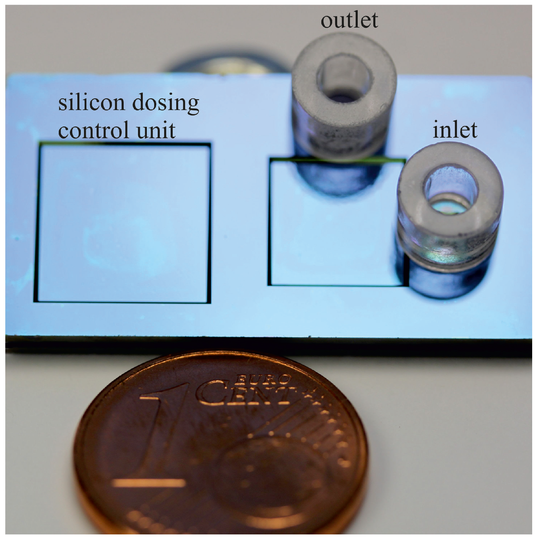
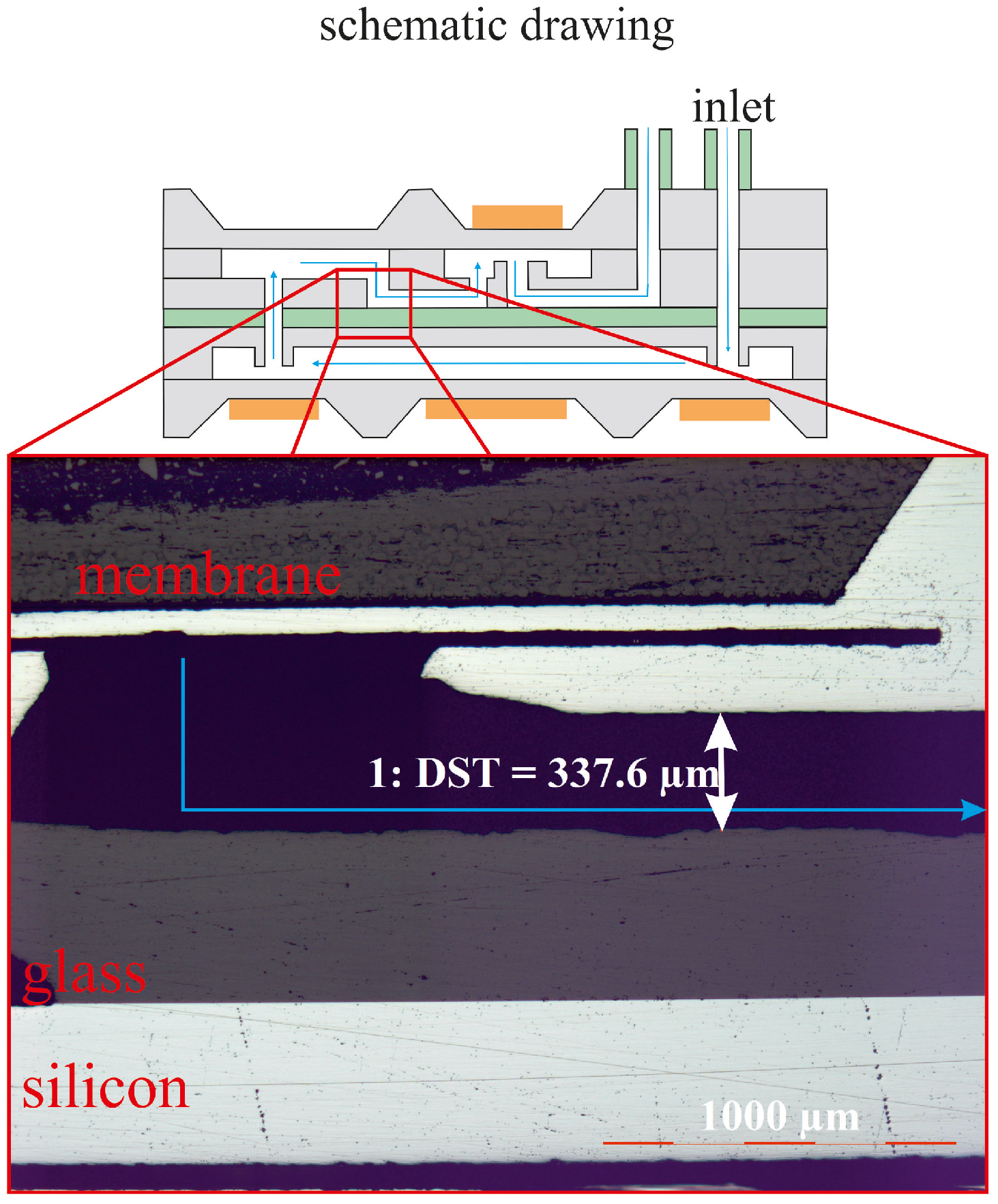
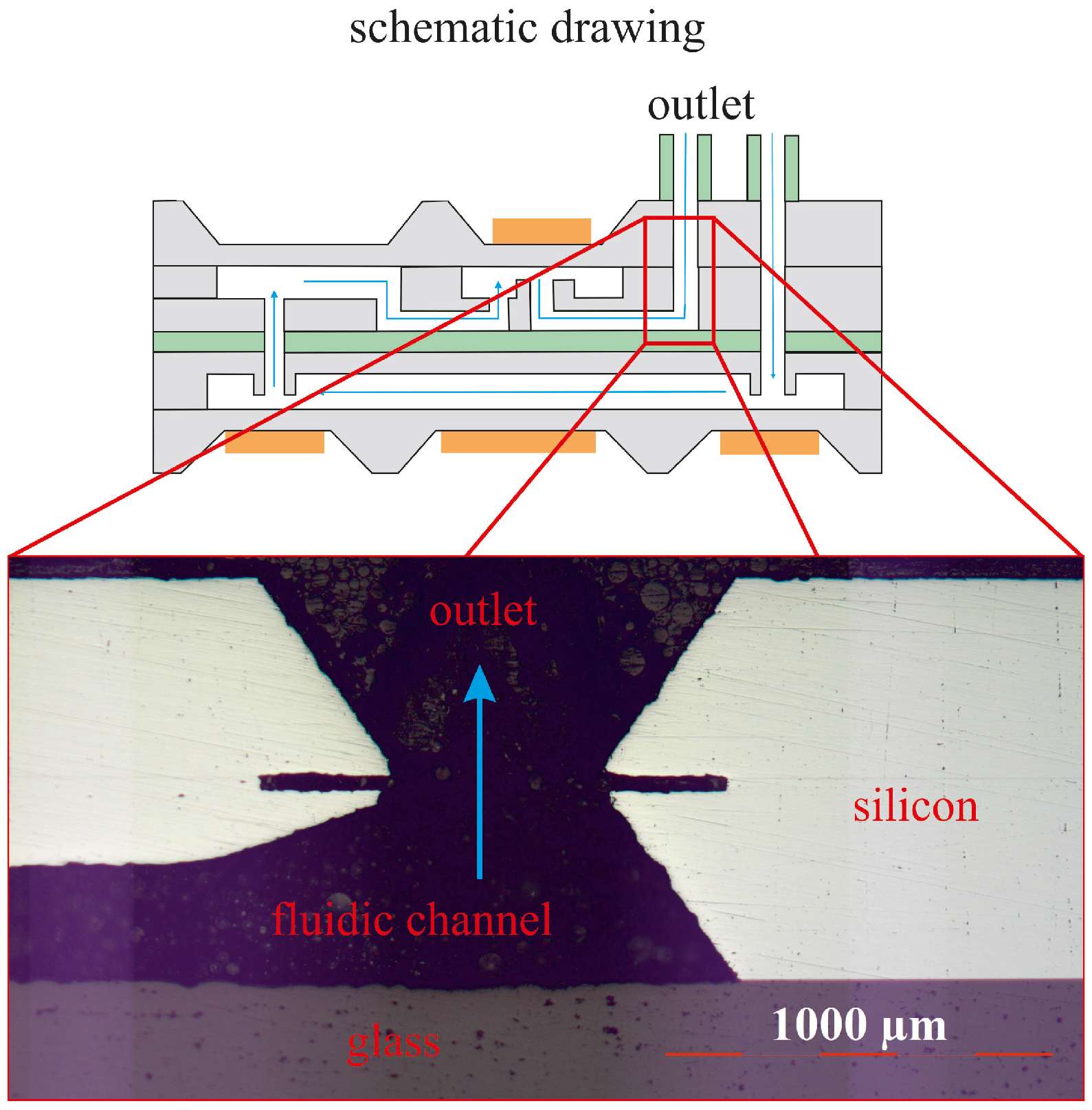
4.1. Preparation of the Fluidic System

For proper bonding results, a piranha etch step of all involved parts, as described in Section 2, has to be done. After that, a baking step, to evaporate moisture, takes place (see Figure 2). A structured Pyrex chip with through-holes was placed between the micropump and dosing unit. The glass tubes were then placed on the inlet and outlet. The goal of the experiment is to achieve a tight fluidic connection between the micropump and the dosing unit without blocking the fluidic channels. This is an obvious requirement, but not guaranteed due to the viscoelasticity of the Pyrex.

4.2. Integration of Micropump and Dosing Unit

Cross-sectional images were taken to analyze the bonding of the micropump and the dosing unit. The schematic drawing in Figure 9 shows the inspected cross sections. Figure 10 shows the inlet of the system after bonding using parameters of Experiment 3, see Table 3, where proper bonding was achieved. This correlates well with the results shown in the initial test in Figure 8. It can also be seen that no fluidic channel or via is closed by melting of the glass, which can be seen in Figure 10. The rounded corners seen in the figure are due to the minimization of surface energy of the glass during the viscoelastic softening. Furthermore, it can be seen that the bonding process does not block the fluidic channels, see Figure 11 and Figure 12.
Figure 9. Schematic 3D drawing of the fluidic system.
Micromachines 05 00783 g009
Figure 10. Cross section view of the fluid inlet. The through-hole in the Pyrex is not closed by melting of the Pyrex.
Micromachines 05 00783 g010
Figure 11. Cross section view of integrated system and dosing device. Cross section of Sections II and 2 in Figure 9.
Micromachines 05 00783 g011
Figure 12. Cross section view of the marked position. Cross section of Sections I and 2, see Figure 9.
Micromachines 05 00783 g012

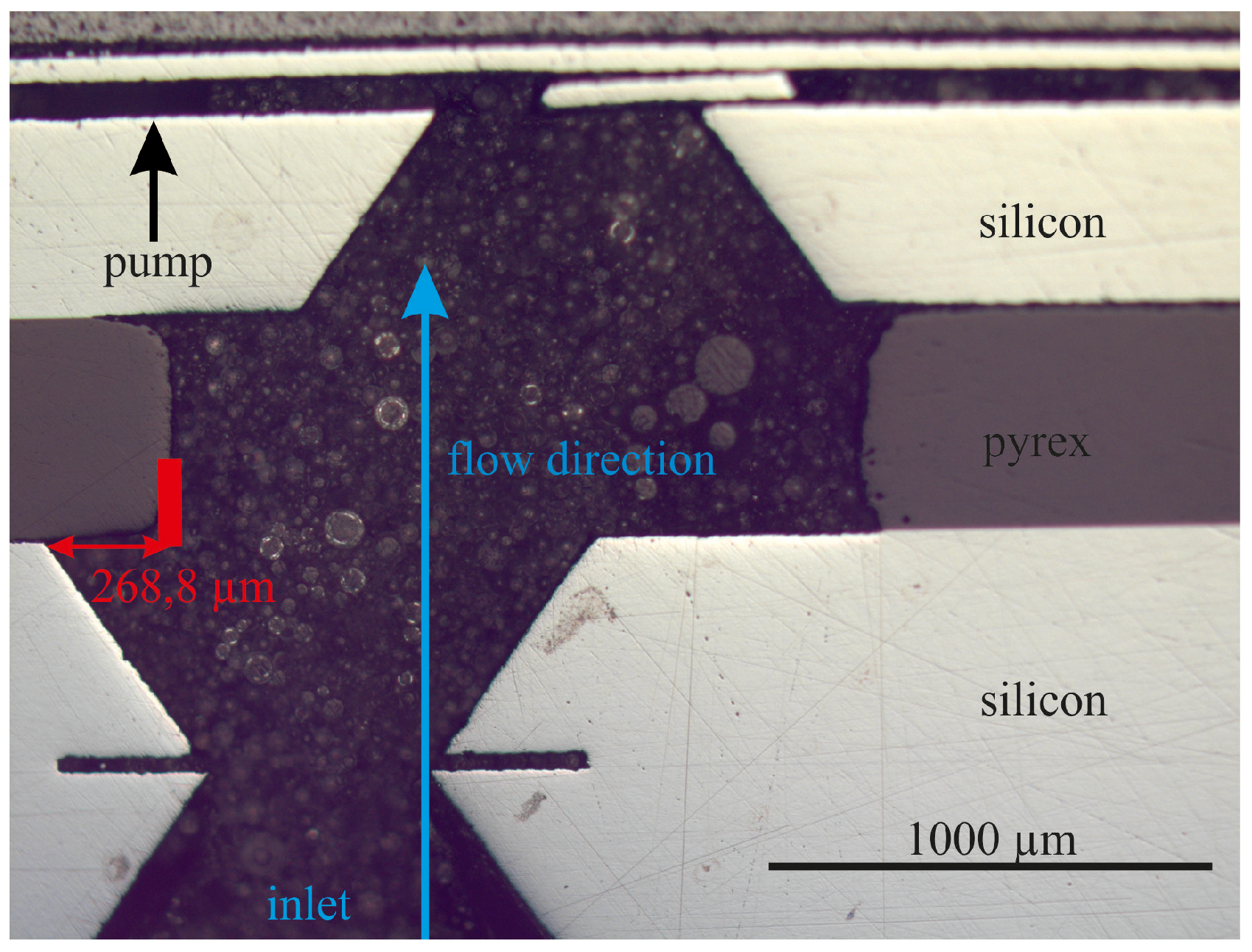
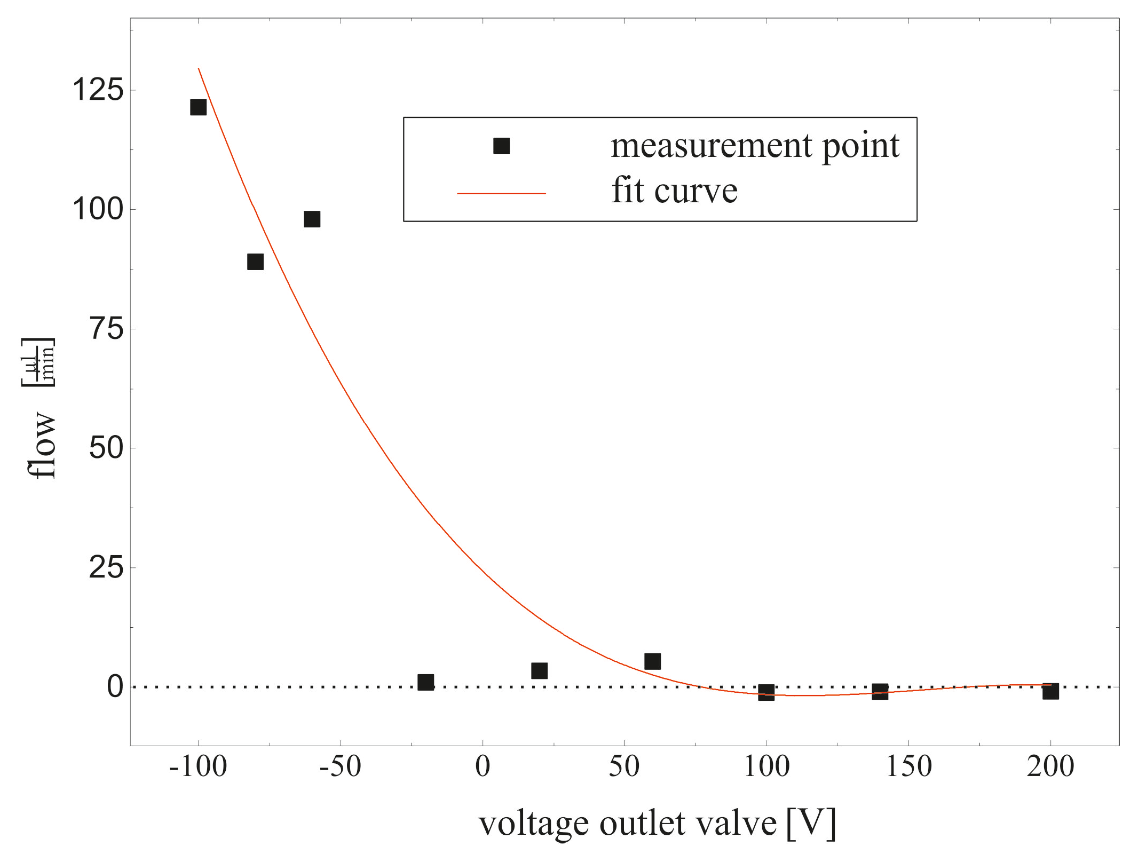
4.3. Fluidic Measurement

In order to proof the functionality of the system, a fluidic measurement is set up, where the pump generates a fluidic flow and the outlet valve of the dosing unit was closed in discrete steps. In order to show that the fluid traverses the entire desired fluidic path, the outlet valve of the dosing unit was closed. Preliminary data on the flow rate generated by the micro-pump are depicted in Figure 13. As can be seen, the flow rate, generated by the pump, decreases with the applied voltage on the piezo-actuator of the outlet valve. This voltage gradually closed the outlet valve in order to increase the fluidic resistance of the system. With this experiment, it can be shown that the flow generated by the pump passes the entire fluidic path and that no blockages or leaks are present. The tested fluidic system can be seen in Figure 14.
Figure 13. Correlation between the fluidic flow, generated by the pump, and the outlet valve position.
Micromachines 05 00783 g013
Figure 14. Bonded fluidic system which is used for the fluidic test. In this picture the piezo-ceramics are not included.
Micromachines 05 00783 g014

5. Conclusions

As can be seen in Figure 10 and Figure 12, the bonding of the silicon to Pyrex shows good results. The bond between silicon and Pyrex is almost free of defects and the microfluidic channels and vias are not blocked by the viscoelastic Pyrex during the bonding process. Furthermore, damage to the thin membranes was never observed after completing the bonding process using these optimized parameters. This observation is a good indicator of a stress-free bonding technique, which correlates well with the thermomechanical stress calculated in the finite element simulation shown in Figure 4. Initial pumping tests were performed with piezoceramic actuators mounted to the thin silicon membranes, which demonstrated the functionality of the fully integrated system without leakage or channel blockage. On the basis of this result, we can conclude that the presented bonding technique is suitable for manufacturing highly integrated and chemically resistant 3D microfluidic systems.

Author Contributions

Florian Thoma designed the bonding technology, carried out the experiments and wrote the paper. Peter Woias and Frank Goldschmidtböing advised the author concerning process technology and bonding technology. Keith Cobry advised the author concerning the simulation.

Conflicts of Interest

The authors declare no conflict of interest.

References

  1. Woias, P. Micropumps: Summarizing the first two decades. In Proceedings of Microfluidics and BioMEMS, San Francisco, CA, USA, 28 September 2001; pp. 39–52.
  2. Lee, C.-Y.; Chang, C.-L.; Wang, Y.-N.; Fu, L.-M. Microfluidic mixing: A review. Int. J. Mol. Sci. 2011, 12, 3263–3287. [Google Scholar]
  3. Haque, R.-U.M.; Wise, K.D. A Glass-in-Silicon Reflow Process for Three-Dimensional Microsystems. J. Microelectromech. Syst. 2013, 22, 1470–1477. [Google Scholar]
  4. Schrag, H.-J.; Ruthmann, O.; Doll, A.; Woias, P.; Hopt, U.T. German Artificial Sphincter System-GASS II: Erste in vivo Evaluation eines neuen hochintegrativen Neosphinkters zur Therapie der hochgradigen Stuhlinkontinenz / Short time in vivo evaluation of a novel and highly integrated sphincter prosthesis for therapy of major fecale incontinence. Biomedizinische Technik/Biomed. Eng. 2005, 50, 371–374. [Google Scholar]
  5. Unnikrishnan, S.; Jansen, H.; Berenschot, E.; Mogulkoc, B.; Elwenspoek, M. MEMS within a Swagelok®: A new platform for microfluidic devices. Lab Chip 2009, 9, 1966–1969. [Google Scholar]
  6. Albaugh, K.B.; Cade, P.E.; Rasmussen, D.H. Mechanisms of anodic bonding of silicon to pyrex glass. In Proceedings of the IEEE Solid-State Sensor and Actuator Workshop, Hilton Head Island, SC, USA, 6–9 June 1988; pp. 109–110.
  7. Despont, M.; Gross, H.; Arrouy, F.; Stebler, C.; Staufer, U. Fabrication of a silicon-Pyrex-silicon stack by a.c. anodic bonding. Sens. Actuators A Phys. 1996, 55, 219–224. [Google Scholar]
  8. Doll, A.; Goldschmidtboeing, F.; Woias, P. Low temperature plasma-assisted wafer bonding and bond interface stress characterization. In Proceedings of the IEEE Solid-State Sensor and Actuator Workshop, Hilton Head Island, SC, USA, 6–9 June 1988; pp. 665–668.
  9. Schott AG. Duran: Röhren, Stäbe und Kapillaren aus Borosilikatglas. Available online: http://www.schott.com/rohrglas (accessed on 18 September 2014).
  10. Harendt, C.; Appel, W.; Graf, H.-G.; Hofflinger, B.; Penteker, E. Wafer fusion bonding and its application to silicon-on-insulator fabrication. J. Micromech. Microeng. 1991, 1, 145. [Google Scholar]
  11. Fazal, I.; Elwenspoek, M.C. Fusion-bonded fluidic interconnects. J. Micromech. Microeng. 2008, 18, 055011. [Google Scholar]
  12. Moğulkoç, B.; Jansen, H.V.; Berenschot, J.W.; Ter Brake, H.J.M.; Knowles, K.M.; Elwenspoek, M.C. Characterization of MEMS-on-tube assembly: Reflow bonding of borosilicate glass (Duran®) tubes to silicon substrates. J. Micromech. Microeng. 2009, 19, 085027. [Google Scholar]
  13. Moğulkoç, B.; Knowles, K.M.; Jansen, H.V.; Ter Brake, H.J.M.; Elwenspoek, M.C. Surface devitrification and the growth of Cristobalite in Borofloatr® (Borosilicate 8330) glass. J. Am. Ceram. Soc. 2010, 93, 2713–2719. [Google Scholar]
  14. Inzinga, R.A.; Lin, T.-W.; Yadav, M.; Johnson, H.T.; Horn, G.P. Characterization and control of residual stress and curvature in anodically bonded devices and substrates with etched features. Exp. Mech. 2012, 52, 637–648. [Google Scholar]
  15. Dage Deutschland GmbH. Datenblatt: Dage Series 4000 Multifunktionstester. Available online: http://www.nordson.com/DE-De/Divisions/Dage/Products/Bondtesters/Pages/4000Optima.aspx (accessed on 18 September 2014).

