Article

Three-Dimensional Glass Monolithic Micro-Flexure Fabricated by Femtosecond Laser Exposure and Chemical Etching

Mechanical Engineering Department, Eindhoven University of Technology, 5600 MB Eindhoven, The Netherlands
*
Author to whom correspondence should be addressed.
Micromachines 2014, 5(3), 697-710; https://doi.org/10.3390/mi5030697
Submission received: 18 August 2014 / Revised: 4 September 2014 / Accepted: 4 September 2014 / Published: 11 September 2014
(This article belongs to the Special Issue Laser Micro- and Nano- Processing)

Abstract

:
Flexures are components of micro-mechanisms efficiently replacing classical multi-part joints found at the macroscale. So far, flexures have been limited to two-dimensional planar designs due to the lack of a suitable three-dimensional micromanufacturing process. Here we demonstrate and characterize a high-strength transparent monolithic three-dimensional flexural component fabricated out of fused silica using non-ablative femtosecond laser processing combined with chemical etching. As an illustration of the potential use of this flexure, we propose a design of a Hoecken linkage entirely made with three-dimensional cross-spring pivot hinges.

Graphical Abstract

1. Introduction

Flexures are essential mechanical elements commonly used in precision and micro-engineering to precisely guide the motion between mechanical bodies. They consist of combinations of slender, continuous bodies that deform elastically upon the application of a force. Flexures [1,2,3] have been used for decades in precision instrumentation and mechanisms [4,5,6,7,8,9,10]. At the microscale, flexures are used in replacement of traditional, multi-part mechanical joints that cannot be easily miniaturized and that are sensitive to friction, wear, and inaccuracies resulting from assembly errors.
The design of flexures at the microscale is essentially constrained by the availability of a material and of a suitable machining process. Commonly used fabrication methods have limited flexure design to two-dimensional components.
Here, we demonstrate the fabrication of a three-dimensional flexure—a cross-spring pivot—made out of fused silica glass using femtosecond laser micromachining combined with chemical etching.
This machining process relies on the non-ablative exposure of fused silica to create three-dimensional patterns that are then etched away by immersing the laser-exposed substrate in a chemical solution [11] (typically HF or KOH [12]). This process not only offers the ability to manufacture high-aspect ratio three-dimensional microstructures, but also to integrate structural elements with other functionalities such as optical waveguides [13,14]. This unique capability has paved the way for monolithic optomechanical devices [15] in which flexures are combined with optical waveguides to achieve embedded sensing functions. The machining of three-dimensional structures in a dielectric and transparent substrate such as fused silica offers additional benefits such as the possibility to implement separated conductive tracks and to be optically transparent. As an illustration, a monolithic optically transparent capacitive glass actuator was recently demonstrated [16]. As shown for femtosecond micromachined Foturan glass substrates [17,18], electrodes-less metal plating [19] may also provide an alternative solution for integrating electrical functionalities. Finally, recent advances in beam shaping methods (like for instance the use of holographic methods [20]) will further expand femtosecond laser processing capabilities.
Although counterintuitive at first, fused silica (the glass used in this study), has a very high mechanical strength if its surface is free of defects. In particular, we demonstrated that flexures with an ultimate tensile strength in excess of 2 GPa can be manufactured with femtosecond laser processing [21]. These high stress levels are well above those (usually below 500 MPa) typically found in commonly used flexure construction materials such as spring steel or aluminum used at the macro-scale.
Finally, in this paper, we illustrate the design of a complete Hoecken linkage [22,23,24] utilizing three-dimensional cross-pivots as an example of complex monolithic mechanical devices.

2. The Cross-Pivot as an Elemental Flexure

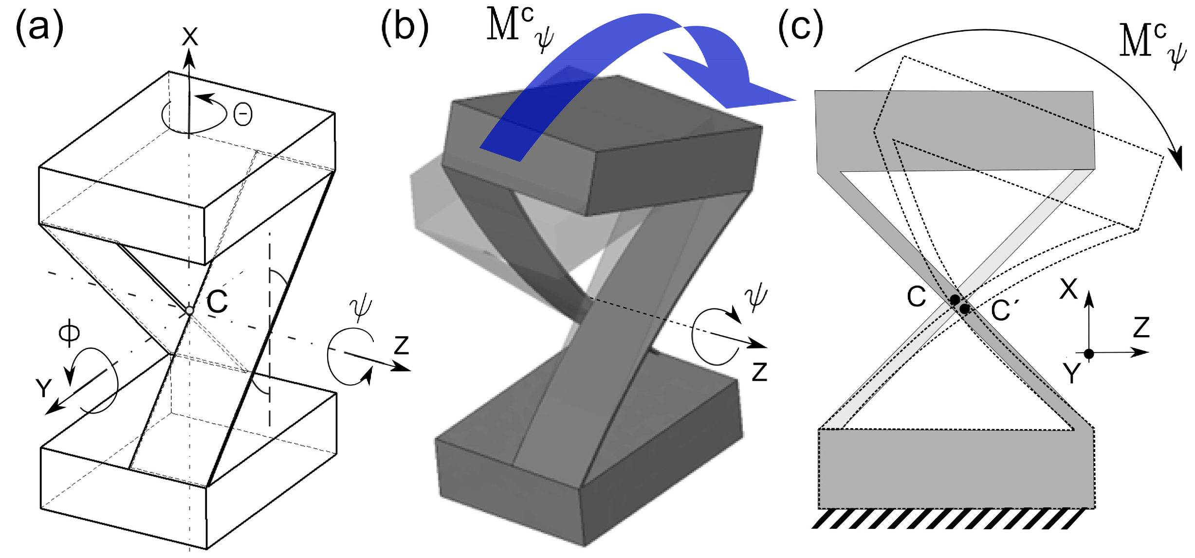
2.1. Working Principle and Relevance

In flexure-based mechanisms, a pivot function is replaced with cantilevers, notch hinges or cross-spring pivots. An ideal pivot flexure should have a fixed center of rotation, a small stiffness along the pivoting degree of freedom and an “infinitely” high stiffness along the other unwanted degrees of freedom. The later property is referred to the flexure stiffness contrast.
The cantilever is a hinge with a large range of motion because of its ability to spread the stress across its entire geometry. As it will be emphasized later, it suffers from the drift of the point of rotation and from a weak stiffness contrast, making it a three-degree-of-freedom flexure as opposed to a single degree of freedom as prescribed for a pivot function. The classical notch hinge has a well-defined point of rotation, which helps in mimicking conventional, friction-based joints, but is subject to detrimental high stress concentrations. Like for the cantilever, it also suffers from a poor stiffness contrast.
The cross pivot hinge, shown in Figure 1, combines the appealing properties of a cantilever and a notch hinge into one. Its crossed structure limits the drift of the point of rotation while keeping large range motion, and the lack of notches prevents stress concentrations. The main limitation of the cross-pivot is its inherent geometrical complexity and its non-trivial, intrinsically three-dimensional shape. In particular, at the micro-scale, such a flexure cannot be fabricated by conventional means such as commonly used lithographic processes like so-called Deep Reactive Ion Etching (DRIE).
Figure 1. Working principle of a cross-spring pivot. (a) Geometrical definition: the cross-spring pivot—in its simplest form—consists of two leaf-springs defining a cross that connects two rigid bodies. (b) Three-dimensional rendering of the deformed shape of a classical cross-pivot upon the application of a pure moment (from an actual finite element simulation). The light grey shadow shows the structure at rest. The cross-spring mimics a pivot joint function. (c) Side view schematic. The rotation axis of the hinge is found at the intersection between the two leaf-springs. While deforming, the position of the center of rotation is subject to a parasitic displacement.
Micromachines 05 00697 g001

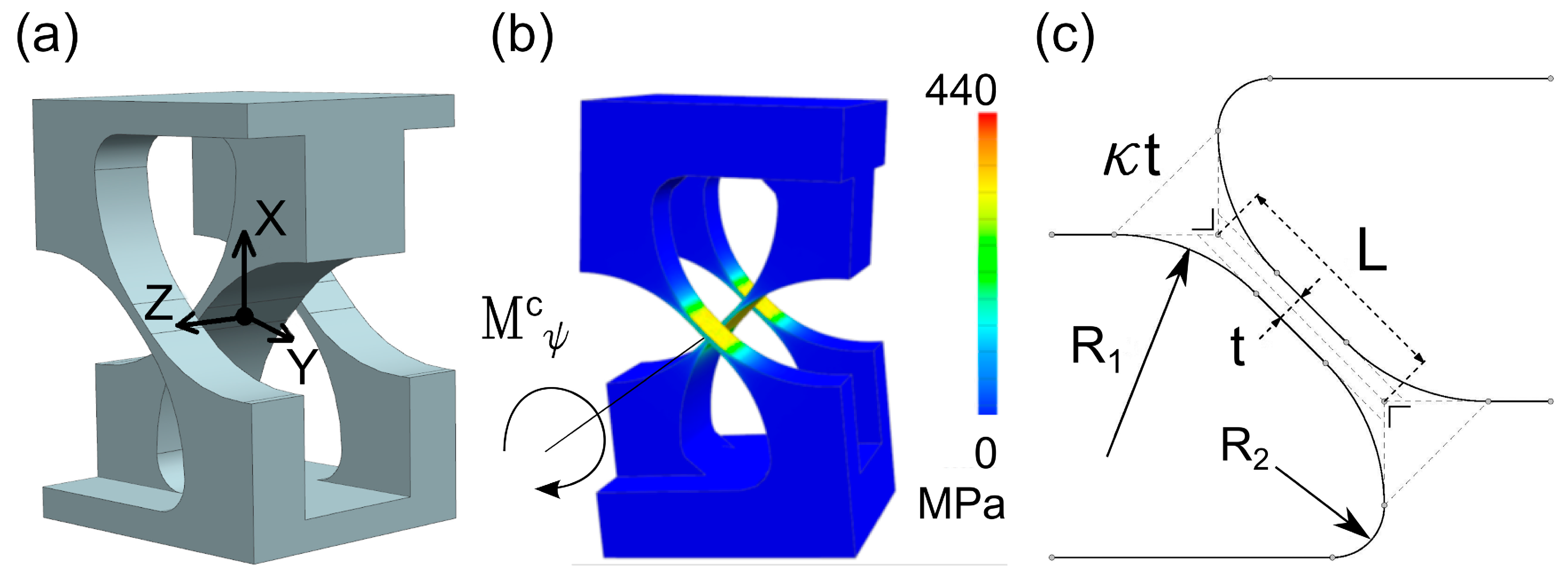
2.2. Stiffness Modeling of the Classical Cross-Spring Pivot

A convenient way to rapidly derive the stiffness properties of complex assembly of flexural elements is to use a method derived from robotics and screw theory [25,26,27]. The stiffness matrix for a flexure that connects two rigid bodies (labelled 0 and 1) and expressed at an arbitrarily chosen point P, in its generalized form can be written as:
Micromachines 05 00697 i001
Where the left term f represents the wrench (a six-coordinates vector containing force and moment) and the right term the 6 × 6 generalized stiffness matrix K times a displacement spatial vector r that contains a linear displacement and an angular component. In the case of the cross-spring pivot, the methodology (described in great detail in [27]) for deriving the generalized stiffness, consists of, first, expressing the stiffness matrix of the beams [28] in a local coordinate frame and center of inertia, and second, to use coordinate transformations (here a rotation of π/4 and a translation of half the beam width) to express the two springs’ stiffnesses at the same point and in the same coordinate frame.
The resulting stiffness matrix for the cross-spring pivot is simply the sum of the two elementary spring matrices, since both are connected in parallel to the same bodies. The end result is shown below. In these formulas, the flexure component of lowest stiffness that defines its preferred degree-of-freedom is highlighted in a box.
Micromachines 05 00697 i002
With the diagonal terms expressed as follow:
Micromachines 05 00697 i003
The non-diagonal terms are:
Micromachines 05 00697 i004
In these formulas, E, w, t and L are the Young modulus of the spring material, the width, the thickness, and length of the individual springs, respectively. υ is the Poisson coefficient of the spring material. The axis notations and the location of point C are shown in Figure 1a.
Non-diagonal terms in the stiffness matrix can be undesired as it implies non-pure transformation from a given axis of application of force into an actual displacement along another axis. For instance, a force applied along the y-axis will result in a displacement along the y-axis as well as an out-of-plane deformation by rotation along the same axis. In the ideal case, only a pure rotation would be applied around the z-axis to activate the pivot-function. In practice, pivot flexures are integrated into more complex mechanisms and the moment causing the pivot rotation is not just along a single axis but rather a combination of force and moment (wrench). In order to achieve high precision in the design of a planar mechanism that uses cross-spring pivots, it is useful to cancel non-diagonal terms that can be activated through in-plane forces and that may cause unwanted, out-of-plane parasitic displacements. Some of the non-diagonal terms can be zeroed through optimization of the flexure design as it will be shown in the next paragraph.

2.3. Design Optimization

By adding a third beam, two of the non-diagonal terms are efficiently suppressed. The optimized design is shown in Figure 2. The shape is further optimized using finite element modeling for reducing stress concentration in a monolithic design (Figure 2c)
Figure 2. (a) 3D rendering of the optimized design for the monolithic cross-spring pivot hinge, showing the addition of the third beam and the removal of sharp edges in geometry to prevent high stress concentrations. Point C refers to the origin of the coordinate frame. (b) Finite element simulation of the designed hinge subjected to a moment applied around the z axis. The model is meshed using tetrahedral elements of 3 μm at the thinnest part of the crossed beams. (c) Geometrical parameters for a single beam.
Micromachines 05 00697 g002
Compared to the original matrix in (2), in matrix (5) shown below, the off-diagonal terms are replaced by two different ones that relate to an out-of-plane coupling (moment applied around θ and ϕ) that cannot be activated by a force applied in the geometrical plane of operation for the hinge. (Note that we keep the same axis notations than in the previous case. This time point C is located in the middle of the middle bar, i.e., the origin of the coordinate frame in Figure 2a.)
Micromachines 05 00697 i005
With the stiffness terms written as (the natural degree of freedom stiffness is emphasized):
Micromachines 05 00697 i006
In these equations, w is the thickness of the central beam. The two thinner, outer beams have a width of w/2. The stiffness of the remaining non-diagonal term is:
Micromachines 05 00697 i007
And the parametric equation that defines the curvature of the anchoring points for the beams (see Figure 2c for the meaning of the various parameters) that prevents stress concentration is expressed as:
Micromachines 05 00697 i008
To qualitatively compare the performances of cross-spring pivots with other flexure pivot designs, we examine the stiffness contrast of the optimized design. By stiffness contrast, we mean the ratio between angular and linear stiffness along each axis. To do so, we consider the weakest stiffness and evaluate the ratio of this stiffness with the other stiffer axis. An ideal pivot should have the highest possible contrast between the stiffness of its natural degree of freedom and that of the other axis. To make the comparison effective and to have it only dependent on one parameter, we assume the same scaling factor between the length of the beam versus its widths and the width versus its thickness. This translates into the following expression, where s is a scaling factor:
L = s·w = s2·t
A typical order of magnitude for s to satisfy well beam-theory conditions is s ≥ 10.
Introducing the expression (9) above in the stiffness relations for the optimized cross-pivot, yields:
Micromachines 05 00697 i009
A pure moment is difficult to apply in practice, especially in a complex design involving more than one pivot flexure. Instead, a pseudo-moment is applied, i.e., a force off the axis passing through the pivot center of rotation, that eventually induces the hinge rotation. Since in flexures, stiffnesses are finite, the force applied to generate the pivoting moment also induces a displacement along its axis that slightly modifies the loading case, and may create a parasitic displacement. It is therefore useful to examine which displacement will prevail in such situation (between angular—the desired pivot rotation and linear—the parasitic motion). To compare angular stiffness (in N·m/rad) and linear stiffness (N/m), we compare a force applied along the rotation axis at a characteristic distance L (equivalent to the characteristic length of the longest element of the beam) from the pivot axis.
For the cross-spring pivot, we obtain (using the axis notations from Figure 2):
Micromachines 05 00697 i010
This result can be interpreted as follows: a force F applied at a distance L from the center of rotation and along the y axis will induce a pivoting moment along the z axis, in addition to the force F along the y axis. The force along the y axis induces a natural parasitic displacement along y of Δy. This parasitic displacement is compared to the amplitude of displacement, called Δyeq, along the same axis but caused by the rotation of the hinge. In the ideal situation of a perfect pivot, the ratio between Δyeq and Δy should be infinite. Using the same methodology, we compare the performances of the optimized cross-spring pivot in terms of stiffness contrast and off-axis behavior with those of a classical cantilever with similar characteristic dimensions (i.e., length L, width w and thickness t). The results are shown in the Table 1.
Table 1. Stiffness contrast for the cross-spring pivot, compared with a cantilever, one of the most used flexure as pivot.
Stiffness component Micromachines 05 00697 i011 Micromachines 05 00697 i012 Micromachines 05 00697 i013 Micromachines 05 00697 i014 Micromachines 05 00697 i015 Micromachines 05 00697 i016 Micromachines 05 00697 i017
Cross-spring pivot Micromachines 05 00697 i018 Micromachines 05 00697 i0181 Micromachines 05 00697 i019 Micromachines 05 00697 i02016s4
Cantilevers41s2s2 Micromachines 05 00697 i021112
In this table, the ratios between the lowest stiffness (either angular or linear) and the other stiffness are compared. This table reveals that the cross-spring pivot shows superior stiffness contrast for angular displacement. Indeed, in the case of a cantilever, the hinge can not only pivot along the z-axis (as desired) but also remains weak in torsion. Furthermore, if an off-axis force is applied to induce the pivoting of a cantilever, it will induce an undesired displacement along the y-axis of similar amplitude. A cantilever taken alone can therefore be seen as a three-degree of freedom flexure: It has rather low-stiffness as pivot along the z-axis but also in torsion (around the y-axis) as well as for a linear displacement along the y-axis. In contrast, the cross-spring pivot has globally a high stiffness contrast and is closer to a pure pivot. It can be considered—in the flexure approximation of a degree-of-freedom—as a one-degree-of-freedom pivot. Note that the comparison of Table 1 can be extended to the notch hinge and would yield similar results. Indeed, the notch hinge has similar stiffness contrast behavior to that of a cantilever beam.
The performance of a flexure can also be assessed in terms of maximum angular deflection versus flexure dimensions. The maximum angle for the cross-spring pivot (for both designs, optimized or not) is given by:
Micromachines 05 00697 i022
In which σL is the elastic limit of the material considered, L the longest length of the beam, E the Young’s modulus and t the beam thickness, respectively.
To summarize, in Table 2, we propose a qualitative comparison between the three types of hinge commonly used as pivots. As evaluation criteria, we compare the maximum angular deflection as well as other key performance factors such as drift of the center of rotation and stress concentration.
Table 2. Performance comparison between commonly used elemental flexures and a cross-spring pivot.
PropertyHinge type
Cantilever *Notch hingeCartwheel [1]Cross-spring pivot ***
Drift of the center of rotation (assuming a perfect loading case, i.e., a pure moment applied on the hinge)δ = ζLθ2~0 ** Micromachines 05 00697 i023δ = λLθ2
Maximum angular deflection Micromachines 05 00697 i024 Micromachines 05 00697 i025 Micromachines 05 00697 i026 Micromachines 05 00697 i027
Stress concentrationLowHighMediumLow
Complexity/manufacturabilityLowMediumMediumHigh (3D)
Notes: * For a cantilever, the center of rotation is defined at one third of the cantilever length. The constant ζ is fitted to be approximately 0.0158. ** The drift is order of magnitude smaller than the thinnest part of the hinge itself and therefore negligible. *** The constant λ is 0.118 [6], 0.112 [5], 0.125 [7]. A typical order of magnitude of the rotation center displacement is about 4% of the beam length for a deflection of 45°.
Cantilever, cross-spring and cartwheel pivots present a drift of the center of rotation while operated. The drift is the highest for the cross-spring pivot but remains within a few percent of the beam length. In both cases, stress concentrations are avoided. The cross spring pivot, for similar characteristic dimensions, has two times more angular deflection than the cantilever beam and four times more than a cartwheel hinge [1,29].
Considering this quantitative comparison between the various flexures used as pivots, the cross-spring pivot has a significant number of key advantages, including a high-stiffness contrast that defines a single-degree of freedom and the absence of stress-concentration. The main challenge is its inherent three-dimensional structure, which is difficult to manufacture. While it can be relatively easily implemented at the macro-scale by assembling leaf-springs on a support structure, it has to date never been made in miniaturized versions suitable for microsystems applications.
In the next section, we demonstrate the fabrication of an optimized cross-spring pivot using femtosecond laser processing.

3. Experimental Results

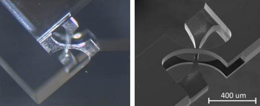
3.1. Device Fabrication

A scanning electron microscope (SEM) and an optical microscope image of a cross-spring pivot fabricated with femtosecond laser and chemical etching are shown in Figure 3. The device is fabricated using a two-step process described in great detail elsewhere [30]. The first step is to expose a 500-µm thick silica substrate (synthetic silica with high OH content) to low-energy pulses, below the ablation threshold. During this step, the material structure is locally modified, resulting in an accelerated HF etching rate in the laser exposed regions.
The exposure step was done with 380 fs-long pulses emitted at 1030 nm from a diode pumped Ytterbium-KGW based femtosecond oscillator (t-Pulse 500 from Amplitude Systèmes, Bordeaux, France). The oscillator emits pulses at a frequency of 9.4 MHz. An acousto-optic modulator (AOM) was used to reduce the repetition rate by chopping out pulses from the main pulse train. For this device, we used a repetition rate of 860 kHz. The laser beam was focused using a 20× objective (OFR-20X-1054, Thorlabs, NJ, USA) with a numerical aperture (NA) of 0.40. Using three linear positioning stages, the specimen was moved with an accuracy of 1 µm under the objective. The writing speeds were 5 and 8 mm/s and the pulse energy was 215 nJ.
The second process step is chemical etching. The laser modified-substrate is dipped into a low-concentration HF bath (from 2.5% to 5%) for 18 h. Although the etchant exposure time varied across the thickness, the tapered profile does not exceed 2 µm over a thickness of 300 µm demonstrating the high-aspect ratio capability of the process.
Figure 3. Scanning Electron Microscope image (left) and microscope image (right) of a cross-pivot hinge as part of a mechanism. The images show the three, crossed beams and the rounded corners at the location where the beams are connected to the main body. Note the high aspect ratio of the micromachining process.
Micromachines 05 00697 g003

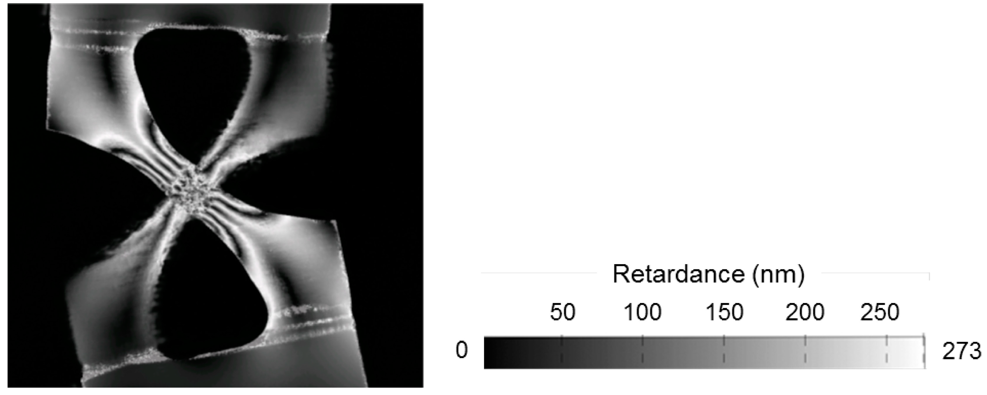
3.2. Stress-Induced Birefringence: Direct Measurement of Stress State in the Flexure

Using transparent substrates in micromechanics offers a distinctive advantage: stress can be observed directly through photoelastic effects. Indeed, the presence of stress induces birefringence that can be quantified and monitored by measuring the retardance and when necessary, the orientation of the principal axes of the birefringence ellipse. In [21], we use photoelasticity to demonstrate that femtosecond laser micromachined notch hinges could withstand very high stress levels, typically above 2 GPa. While it is known that amorphous silica has a theoretically high elastic limit, it has a low fracture toughness that limits its use as a mechanical component. The main difficulty is to achieve sufficiently high surface quality to prevent the formation of cracks. We showed [21] that the etching step in this manufacturing process contributes to extending the maximum stress limit sustainable by femtosecond laser micromachined structure. Here, we use a polarization microscope (LC-Polscope®, CRi, Cambridge, MA, USA) to measure the retardance through a thick cross-pivot structure. The results are shown in Figure 4.
Figure 4. Retardance image (left) of a cross-pivot being deformed, coded in grey levels. The average beam thickness is 60 μm and the bending angle 13 degrees. The observed retardance results from the stress developing in the hinge. By measuring the grey level on the retardance scale (right) modulated by the number of visible fringes, starting from the center were the stress is minimum, the effective maximum stress, 1.9 GPa, present in the flexure is determined using the photoelastic coefficients of fused silica (see [21] for more details).
Micromachines 05 00697 g004
The result in Figure 4 illustrates the stress-state in the material. Since the lever distance—where the force is applied—is several times more than the length of the flexure itself (parameter L in the previous paragraph), and since the angular stiffness around the z-axis is much lower than the linear stiffness in the y-direction, the loading case can be approximated as a pure bending loading case, which is confirmed by these observations. In this flexure, the hinge thickness is rather high (60 µm) leading to high stress level (1.9 GPa in Figure 4) for an angular deformation of 13 degrees from its rest position.
In the following paragraph, we investigate the use of a cross pivot hinge for practical application, such as a linear guidance.

3.3. Integration of the Cross-Spring Flexure in a Pure Linear Guidance

A Hoecken guidance (see Figure 5) [22,23,24] is a quasi-rectilinear guidance made of four pivot joints. It converts a rotational motion into an approximately constant velocity linear motion.
Such rectilinear guidance mechanisms are difficult to design using classical hinges due to the range motion requirements (inducing high-stress and large deflection in the hinge) as well as the joints spatial arrangements causing a non-uniform loading of the pivots. Cross-spring pivots offer an interesting solution since the load is distributed instead of being concentrated. Furthermore, as illustrated in the previous paragraph, for the same maximum stress value, a cross-spring pivot can flex over a larger range and has a higher stiffness contrast, making these stiffness characteristics closer to an ideal one-degree-of-freedom pivot. Figure 6 shows a monolithic glass Hoecken guidance that uses four cross-springs as pivots.
Figure 5. Working principle of a four-bar Hoecken’s linkage. The joints are located in A, B, C and D. The characterized lengths of the segment for this example are indicated on the right. A and B are attached to the fixed world. During operation, point M describes a trajectory characterized with a nearly rectilinear section. This linkage effectively converts a rotation (in A or B) into a quasi-straight motion in M with constant velocity.
Micromachines 05 00697 g005
Figure 6. A monolithic glass Hoecken linear guidance (left) and a sequence of merged images to illustrate the function of the mechanism (right). The end point—i.e., where the linear motion is produced—is the cross in the upper part. The mechanism is activated by moving the rectangular window (left side of the images) along a circle. The linearity is within ±0.5 µm over a displacement of 600 µm.
Micromachines 05 00697 g006
The guidance is entirely manufactured using femtosecond laser micromachining according the process described earlier. The left image shows the complete guidance and the right image (a superposition of images), the deformed structure during operation.
Figure 7 shows the trajectory in the plane of the various key points of the guidance. The dotted lines are the theoretical trajectory for a Hoecken linkage when pivots achieve a complete revolution. The solid lines are the trajectory of the point in the case of the flexure, for which pivots have limited excursions.
Figure 7. (Left): Trajectory of various key points selected on the Hoecken linear guidance (as shown in the (right) photograph). The dotted lines are the theoretical trajectory for a full rotation of the pivots while the continuous line is the actual range motion of the flexure cross-spring pivots.
Micromachines 05 00697 g007

4. Conclusions

Among the various designs of flexure pivots, we have shown that the cross-spring pivot, in comparison to other elemental flexures used in microsystems design has superior performances in terms of stiffness contrast, range of motion and approximation of an ideal one-degree of freedom pivot. To date, the manufacture of cross-pivot hinges has been limited by the lack of available, micro-manufacturing processes, suitable for producing three-dimensional structures.
Here, we have demonstrated that, using of femtosecond laser processing combined with chemical etching, such complex three-dimensional flexure pivots can be manufactured, offering new opportunities for novel monolithic flexure-based mechanisms, which were previously impossible to fabricate using conventional means. As an illustration of the potential of the femtosecond laser machining of glass substrates, we have shown the integration of this cross-spring pivot in a glass transparent Hoecken guidance mechanism.
To the best of our knowledge, this is the first example of monolithic and non-trivial three-dimensional hinges fabricated at the micro-scale.

Acknowledgments

The authors acknowledge the partial financial support of the European Commission (Femtoprint project, FP7—NMP, Factory of the Future initiative) and of the European Research Council (Galatea project, ERC-2012-StG-307442).

Author Contributions

Viktor Tielen, during his master thesis, performed the experiments and fabricated the various flexures presented here. He optimized the design of the flexure to improve its stiffness characteristics and made the design of the Hoecken glass linkage. Yves Bellouard designed and supervised the research, wrote the manuscript and performed the comparative theoretical analysis between flexures.

Conflicts of Interest

The authors declare no conflict of interest.

References and Notes

  1. Smith, S.T. Flexures: Elements of Elastic Mechanisms; CRC Press: Boca Raton, FL, USA, 2000. [Google Scholar]
  2. Lobontiu, N. Compliant Mechanisms: Design of Flexure Hinges; CRC Press: Boca Raton, FL, USA, 2010. [Google Scholar]
  3. Howell, L.L. Compliant Mechanisms; John Wiley & Sons: Hoboken, NJ, USA, 2001. [Google Scholar]
  4. Sears, J.E. A symmetrically opening optical slit. J. Sci. Instrum. 1933, 10, 376–377. [Google Scholar] [CrossRef]
  5. Haringx, J.A. The cross-spring pivot as a constructional element. Appl. Sci. Res. 1949, 1, 313–332. [Google Scholar] [CrossRef]
  6. Wittrick, W.H. The theory of symmetrical crossed flexure pivots. Aust. J. Sci. Res. Ser. A Phys. Sci. 1948, 1, 121–134. [Google Scholar]
  7. Mesnager, A. Sur les articulations à lames flexibles. Comptes rendus Hebdomadaires des Séances de l’Académie des Sciences 1903, 137, 908–909. (In French) [Google Scholar]
  8. Jones, R. V. An optical slit mechanism. J. Sci. Instrum. 1952, 29, 345–350. [Google Scholar] [CrossRef]
  9. Schellekens, P.; Rosielle, N.; Vermeulen, H.; Vermeulen, M.; Wetzels, S.; Pril, W. Design for precision: Current status and trends. CIRP Ann. Manuf. Technol. 1998, 47, 557–586. [Google Scholar] [CrossRef]
  10. Breguet, J.-M.; Henein, S.; Kjelberg, I.; Gumy, M.; Glettig, W.; Lecomte, S.; Boiko, D.; Mitev, V. Tunable extended-cavity diode laser based on a novel flexure-mechanism. Int. J. Optomechatronics 2013, 7, 181–192. [Google Scholar] [CrossRef]
  11. Marcinkevičius, A.; Juodkazis, S.; Watanabe, M.; Miwa, M.; Matsuo, S.; Misawa, H.; Nishii, J. Femtosecond laser-assisted three-dimensional microfabrication in silica. Opt. Lett. 2001, 26, 277–279. [Google Scholar]
  12. Kiyama, S.; Matsuo, S.; Hashimoto, S.; Morihira, Y. Examination of etching agent and etching mechanism on femotosecond laser microfabrication of channels inside vitreous silica substrates. J. Phys. Chem. C 2009, 113, 11560–11566. [Google Scholar] [CrossRef]
  13. Bellouard, Y.; Said, A.; Dugan, M.; Bado, P. Monolithic Three-Dimensional Integration of Micro-Fluidic Channels and Optical Waveguides in Fused Silica. In Proceedings of Materials Research Society Symposium, Warrendale, PA, USA; 2003; pp. 63–68. [Google Scholar]
  14. Bellouard, Y.; Champion, A.; Lenssen, B.; Matteucci, M.; Schaap, A.; Beresna, M.; Corbari, C.; Gecevicius, M.; Kazansky, P.; Chappuis, O.; Kral, M.; Clavel, R.; Barrot, F.; Breguet, J.-M.; Mabillard, Y.; Bottinelli, S.; Hopper, M.; Hoenninger, C.; Mottay, E.; Lopez, J. The Femtoprint Project. J. Laser Micro/Nanoeng. 2012, 7, 1–10. [Google Scholar]
  15. Bellouard, Y.; Said, A.; Bado, P. Integrating optics and micro-mechanics in a single substrate: A step toward monolithic integration in fused silica. Opt. Express 2005, 13, 6635–6644. [Google Scholar] [CrossRef] [PubMed]
  16. Lenssen, B.; Bellouard, Y. Optically transparent glass micro-actuator fabricated by femtosecond laser exposure and chemical etching. Appl. Phys. Lett. 2012, 101, 103503. [Google Scholar] [CrossRef]
  17. Cheng, Y.; Sugioka, K.; Midorikawa, K.; Masuda, M.; Toyoda, K.; Kawachi, M.; Shihoyama, K. Three-dimensional micro-optical components embedded in photosensitive glass by a femtosecond laser. Opt. Lett. 2003, 28, 1144–1146. [Google Scholar] [CrossRef] [PubMed]
  18. Juodkazis, S.; Yamasaki, K.; Mizeikis, V.; Matsuo, S.; Misawa, H. Formation of embedded patterns in glasses using femtosecond irradiation. Appl. Phys. A. 2004, 79, 1549–1553. [Google Scholar]
  19. Sugioka, K.; Masuda, M.; Hongo, T.; Cheng, Y.; Shihoyama, K.; Midorikawa, K. Three-dimensional microfluidic structure embedded in photostructurable glass by femtosecond laser for lab-on-chip applications. Appl. Phys. A: Mater. Sci. Process. 2004, 79, 815–817. [Google Scholar]
  20. Hasegawa, S.; Hayasaki, Y. Holographic vector wave femtosecond laser processing. Int. J. Optomechatronics 2014, 8, 73–88. [Google Scholar] [CrossRef]
  21. Bellouard, Y. On the bending strength of fused silica flexures fabricated by ultrafast lasers. Opt. Mater. Express 2011, 1, 816–831. [Google Scholar] [CrossRef]
  22. While it seems that the paternity of this linkage is to be attributed to Karl Hoecken (see [24]), the name Hoecken seems often misspelled and sometimes, this linkage is referred as Hoeken or Hoekens linkage, see for instance [23].
  23. Lu, S.; Zlatanov, D.; Ding, X.; Molfino, R. A new family of deployable mechanisms based on the Hoekens linkage. Mech. Mach. Theory 2014, 73, 130–153. [Google Scholar] [CrossRef]
  24. Kerle, H. About Karl Hoecken and Some of His Works on Mechanisms. In Explorations in the History of Machines and Mechanisms: Proceedings of HMM2012; Koetsier, T., Ceccarelli, M., Eds.; Springer Netherlands: Dordrecht, The Netherlands, 2012; Volume 15, pp. 123–134. [Google Scholar]
  25. Loncaric, J. Normal forms of stiffness and compliance matrices. IEEE J. Robot. Autom. 1987, 3, 567–572. [Google Scholar] [CrossRef]
  26. Ding, X.; Selig, J.M. On the compliance of coiled springs. Int. J. Mech. Sci. 2004, 46, 703–727. [Google Scholar] [CrossRef]
  27. Bellouard, Y. Microrobotics: Methods and Applications; CRC Press: Boca Raton, FL, USA, 2010. [Google Scholar]
  28. Von Mises, R. Motorrechnung, ein neues hilfsmittel in der mechanik. J. Appl. Math. Mech./Z. Angew. Math. Mech. 1924, 4, 155–181. (In German) [Google Scholar]
  29. Shusheng, B.; Hongzhe, Z.; Jingjun, Y. Modeling of a cartwheel flexural pivot. J. Mech. Des. 2009, 131, 061010. [Google Scholar] [CrossRef]
  30. Bellouard, Y.; Said, A.; Dugan, M.; Bado, P. Fabrication of high-aspect ratio, micro-fluidic channels and tunnels using femtosecond laser pulses and chemical etching. Opt. Express 2004, 12, 2120–2129. [Google Scholar] [CrossRef] [PubMed]

