Article

Structural Design and Experimental Analysis of a Piezoelectric Vibration Feeder with a Magnetic Spring

Institute of Mechanical Science and Engineering, Jilin University, Changchun 130022, China
*
Author to whom correspondence should be addressed.
Micromachines 2014, 5(3), 547-557; https://doi.org/10.3390/mi5030547
Submission received: 25 June 2014 / Revised: 2 August 2014 / Accepted: 5 August 2014 / Published: 19 August 2014
(This article belongs to the Special Issue Microactuators)

Abstract

:
A piezoelectric vibration feeder with a magnetic spring is discussed in this paper. The feeder can keep resonance frequency relatively stable under changing loading. Through the analysis on the working principle and magnetic spring stiffness characteristic of this feeder, the dynamic model was established and the relationship among system resonance frequency, loading and magnetic spring stiffness was obtained. The analysis showed that, as the loading changed, the magnetic spring stiffness changed accordingly, which maintained a trend of stability in the system resonance frequency. A prototype was made for the experiment, and the relationship among the loading, magnetic spring axial clearance and system resonance frequency was obtained. The result showed that, when the loading changes, the resonance frequency and feeding speed tended to be stable, which matched the theoretical analysis. Through comparison with a traditional vibration feeder, within nominal loading, this new feeder has more stable resonance frequency and feeding speed.

1. Introduction

Because of good patterning, guiding performance, and high efficiency, a vibrating feeder is widely used in automatic assembly, processing and inspection, etc. [1]. The traditional vibrating feeder takes mainly mechanical or electromagnetic drives, but there are disadvantages, like high noise level, low feeding accuracy, high power consumption, and easily interfered by electromagnetism, and so on [2]. With the advanced industry development, the demand on vibrating feeder is increasing greatly. In the end of 1970s, Japan invented rectangular piezoelectric bimorph as the driving source for cantilever piezoelectric vibrating feeder [3]. There have been more invention patents and related research on different structure feeders since then [4,5,6]. The spiral piezoelectric vibrating hopper was invented in the USA. It had adverse phase AC voltage and the piezoelectric film drove the spring leaf vibration back and forth [7]. The agile manufacturing and system lab in Inha University South Korea invented a new piezoelectric feeder. Finite Element Analysis (FEA) and experiment analysis were done on the feeder [8]. Taiwanese researchers analyzed the linear piezoelectric vibration feeder. The Rayleigh-Ritz method, model and experiment were carried out to ascertain the factors that influence system feeding speed [9]. Nowadays, in China, some universities are working on piezoelectric vibrating feeder research [10,11,12,13,14,15,16,17,18], such as Tianjin University, Dalian Science and Technology University, Nanjing University of Aeronautics and Astronautics, Jilin University, etc.
To increase efficiency, feeders are usually working at resonance conditions. During feeding, once the materials are put on the feeder, with the feeding, the material mass reduces gradually, since the present feeder has fixed spring stiffness, which cannot change along with the material mass (loading). Therefore, the feeder resonance frequency increases, and the drive output frequency needs to be constantly increased to make the feeder work at resonance conditions. Moreover, when adding materials later, the drive output frequency needs to be reduced back again. Nowadays, the drive with frequency tracking and auto-controlling function is expensive, and there is a lag during working. If the loading changes, the feeder spring stiffness can change accordingly, and then the resonance frequency can function as well. At small deformation, the magnetic spring made of two annular magnets has stable stiffness, and when axial clearance is reduced, the stiffness increases. In addition, with the same structure and size, the annular magnetic spring has good mechanical properties and wide changing range [19,20], which can simplify the system, reduce the noise level, and can eliminate fatigue deformation.
Based on adjustable stiffness of the magnetic spring, a novel piezoelectric resonance feeder is proposed. With theoretical analysis and experiment, the material mass, magnetic spring stiffness and system resonance frequency changes were analyzed initially, and the possibility to stabilize the system resonance frequency with the magnetic spring was validated.

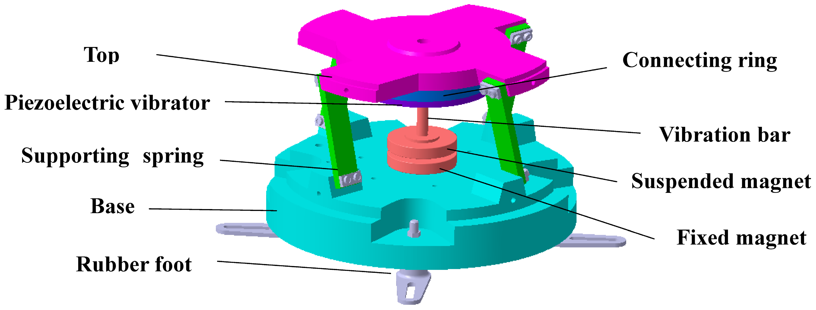
2. Structure and Working Concept

The structure of the magnetic spring piezoelectric vibration feeder is shown in Figure 1 below. The driving source is the piezoelectric bimorph vibrator, which is fixed with the top plate by the mass block. The vibration bar is connected with the centers of the piezoelectric vibrator and suspended magnet, and fixed with nuts from both sides. There is a center-facing in homopolarity between the suspended magnet and permanent magnet. The permanent magnet is mounted in the base, there are rubber feet below the base to reduce vibration, and the base and top plate are connected with a supporting at 75°. The top plate, mass block, connecting ring, piezoelectric vibrator, suspended magnet and vibration bar can be treated in their entirety as a vibration amplified system, while the suspended magnet and permanent magnet with homopolar that face each other can be used as a compressed magnetic spring.
Figure 1. Structure of Magnetic spring piezoelectric vibration feeder.
Micromachines 05 00547 g001
In magnetic spring piezoelectric vibration feeder, sine AC voltage is placed on piezoelectric bimorph vibrator to obtain bending deformation. When the voltage changes, the output displacement of the piezoelectric vibrator changes accordingly, and longitudinal vibration happens, and this vibration forces the supporting springs with the same inclination to create and release the deformation. In this case, longitudinal vibration and torsional movement are combined, and the magnetic spring amplifies the system vibration. In this situation, the material in the tray moves in sequence, and the feeding works.

3. Stiffness Characteristic and Dynamic Model

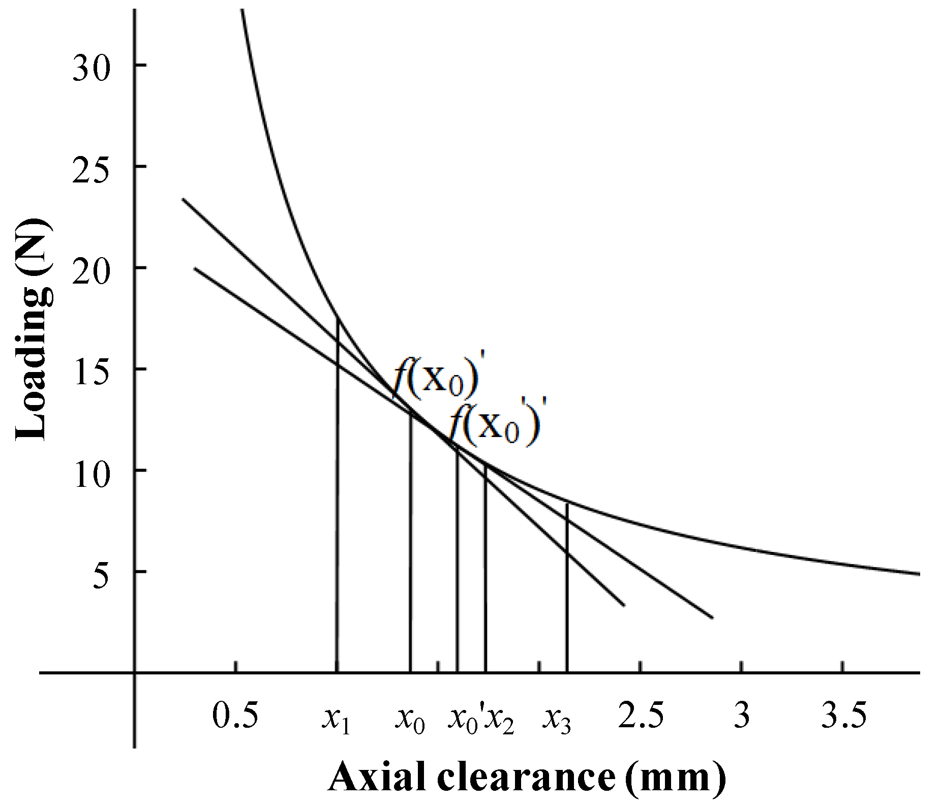
3.1. Magnetic Spring Stiffness Characteristic

Within small displacement of the magnetic spring, the relationship between displacement and loading is close to linear. As shown in Figure 2, take small clearance of the magnetic spring as x1, x2, the middle of x1 and x2 as x0, corresponding value as f(x0), f(x0)’ as the slope, which can be used as the magnetic spring stiffness k0, within small distance. Increase the distance, marked as x3, take the middle of x1 and x3 as x0’, corresponding value f(x0’), f(x0’)’ as the stiffness k0’, between x1 and x3. From the figure, |f(x0)’| > |f(x0’)’|, which means k0 > k0’, shows that, with an increase in distance, the axial stiffness reduces, and vice versa.
Figure 2. Relationship between loading and axial clearance.
Micromachines 05 00547 g002

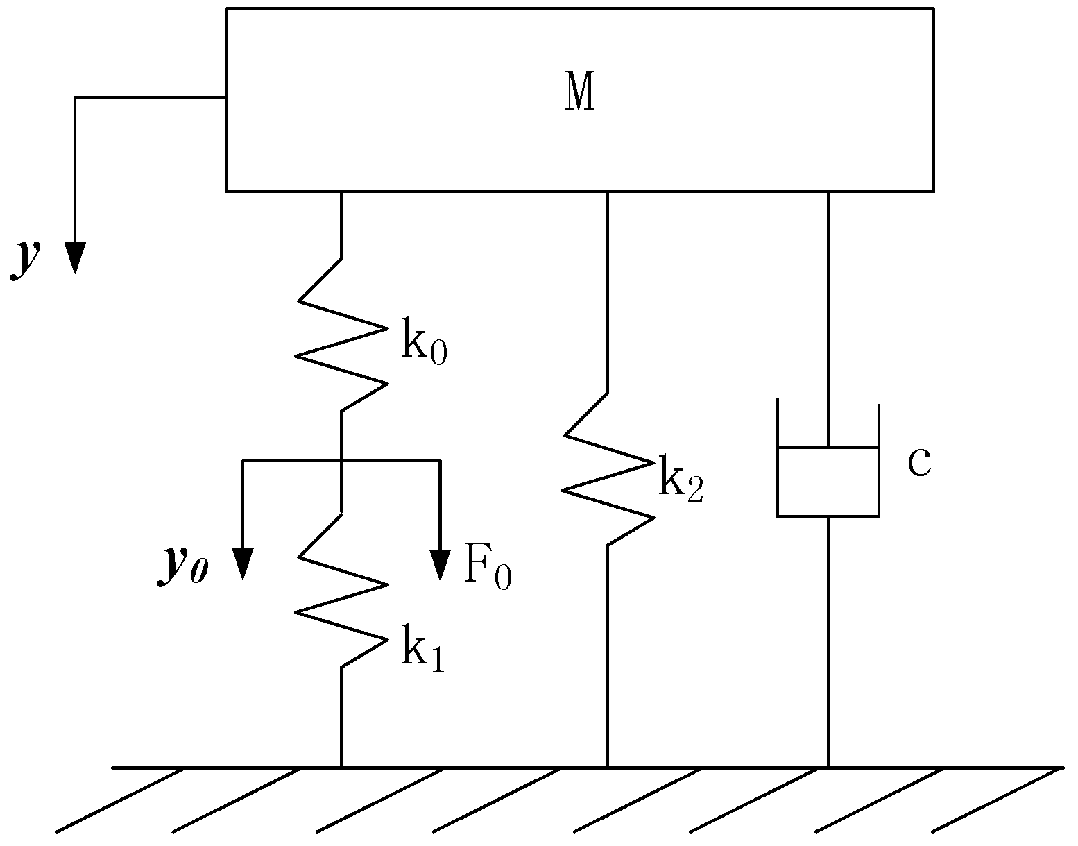
3.2. Dynamic Formula

The mechanical model of the magnetic spring piezoelectric vibration feeder is shown in Figure 3. M is the equivalent mass of the entire system, including top plate, mass block, connecting ring, vibration bar. k0 is the equivalent stiffness of the piezoelectric vibrator, k1 is the stiffness of the magnetic spring. From Section 3.1, the magnetic spring shows linear stiffness within a small distance. Therefore, it can be used for linear calculation. k2 is the stiffness of the supporting spring every 90°. The rubber feet act to reduce the vibration of the spring. If the stiffness is low it can be ignored.
y0 is the vibration displacement of the piezoelectric vibrator. Supposing y0 = Acos (ωt), y is the vibration displacement of the top plate, F0 is the initial excitation, F0 = k0y0 and c is the system equivalent damping. The single degree of freedom with damping forced vibration system has a differential equation of motion
Micromachines 05 00547 i001
which can be transferred as
Micromachines 05 00547 i002
Furthermore,
Micromachines 05 00547 i003
This can be changed to
Micromachines 05 00547 i004
This can be further altered to
Micromachines 05 00547 i005
Then, the system steady-state response
Micromachines 05 00547 i006
Here Micromachines 05 00547 i007.
The system displacement amplified time is
Micromachines 05 00547 i008
When the excitation frequency is the system resonance frequency Micromachines 05 00547 i009, Equation (5) is
Micromachines 05 00547 i010
From Equation (7),
Micromachines 05 00547 i011
To keep the material feeding efficiency, the feeder usually works under resonance conditions. While the loading increases, the mass M increases accordingly. From Equation (5), ωn reduces, and the system resonance frequency decreases accordingly. In Equation (8), when the mass M increases, the stiffness k1 increases accordingly, which enables the resonance frequency to be unstable. From Equation (7), when the displacement magnification factor |H(ω)| reduces, the feeding speed decreases; when the mass M reduces, the stiffness k1 decreases accordingly, and the system resonance frequency can stay stable without changes, but the displacement magnification factor |H(ω)| increases, and the feeding speed increases.
Figure 3. Dynamic model of the magnetic spring piezoelectric vibration feeder.
Micromachines 05 00547 g003

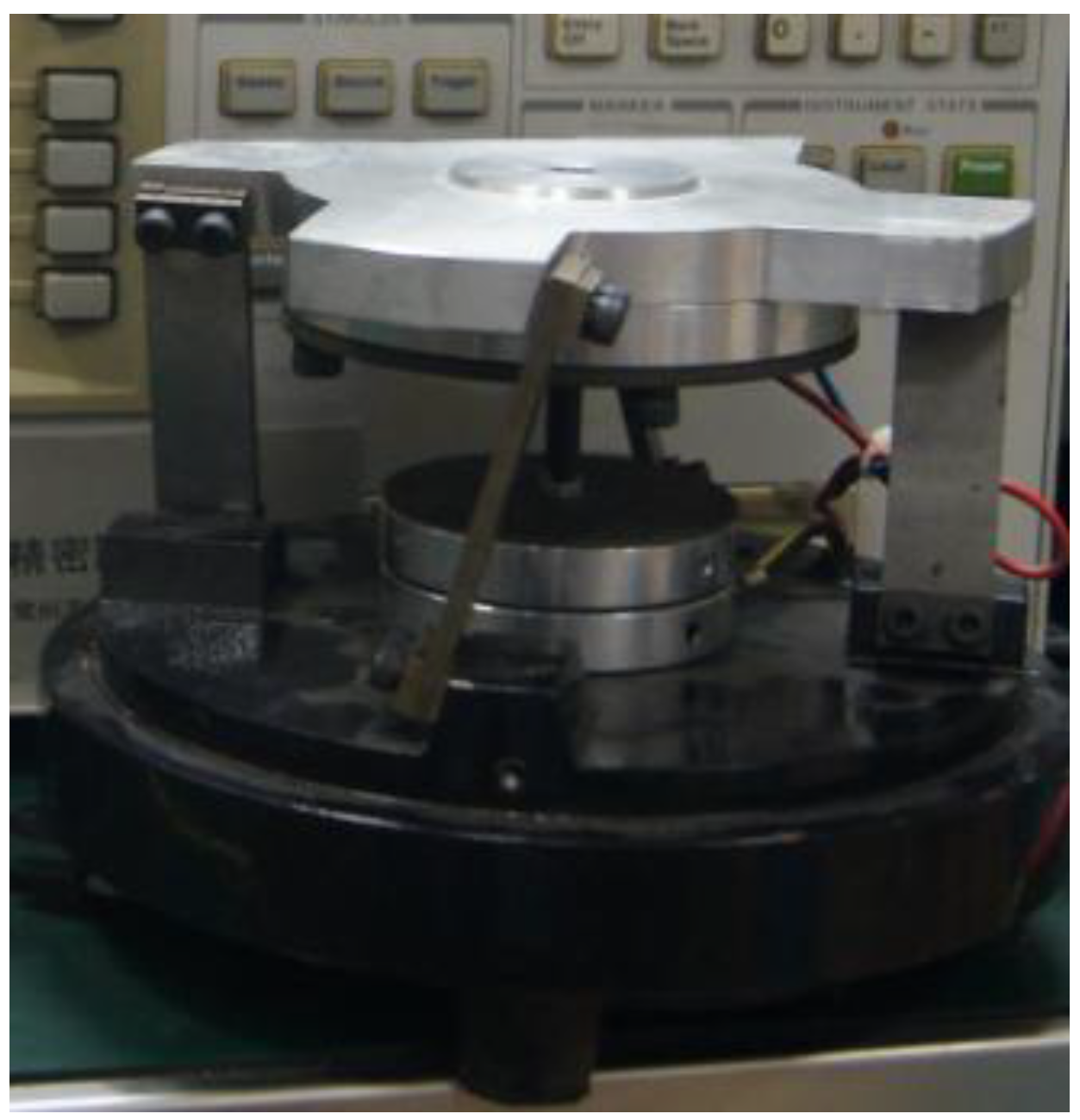
4. Performance Experiment

The excitation voltage is 200 V, the detailed information please refer to Table 1 below:
Table 1. Main components information.
ItemMaterialOuter diameter (mm)Inner diameter (mm)Thickness (mm)
Annular ceramic plate*60Si2MnA50100.6
Annular base plate *65 Mn7241.8
Annular magnetNdFeB601510
Top plateAluminum AlloyDiameter: 120 mm
Supporting spring65 MnFour springs located every 90°, tilt angle 75° between base and top plate
Base45#
Vibration-reducing springBlack rubber
*: especially made for the piezoelectric vibrator.
Figure 4 shows the experiment equipment. The equipment includes an Agilent HP4294 precise impedance analyzer, SDVC40-M digital piezoelectric frequency modulation controller, Keyence LC-2400 laser micrometer, electronic weighing device, tray, and materials for feeding. The prototype is shown in Figure 5.
Figure 4. Experiment equipment.
Micromachines 05 00547 g004
Figure 5. Prototype of piezoelectric vibration feeder with magnetic spring.
Micromachines 05 00547 g005

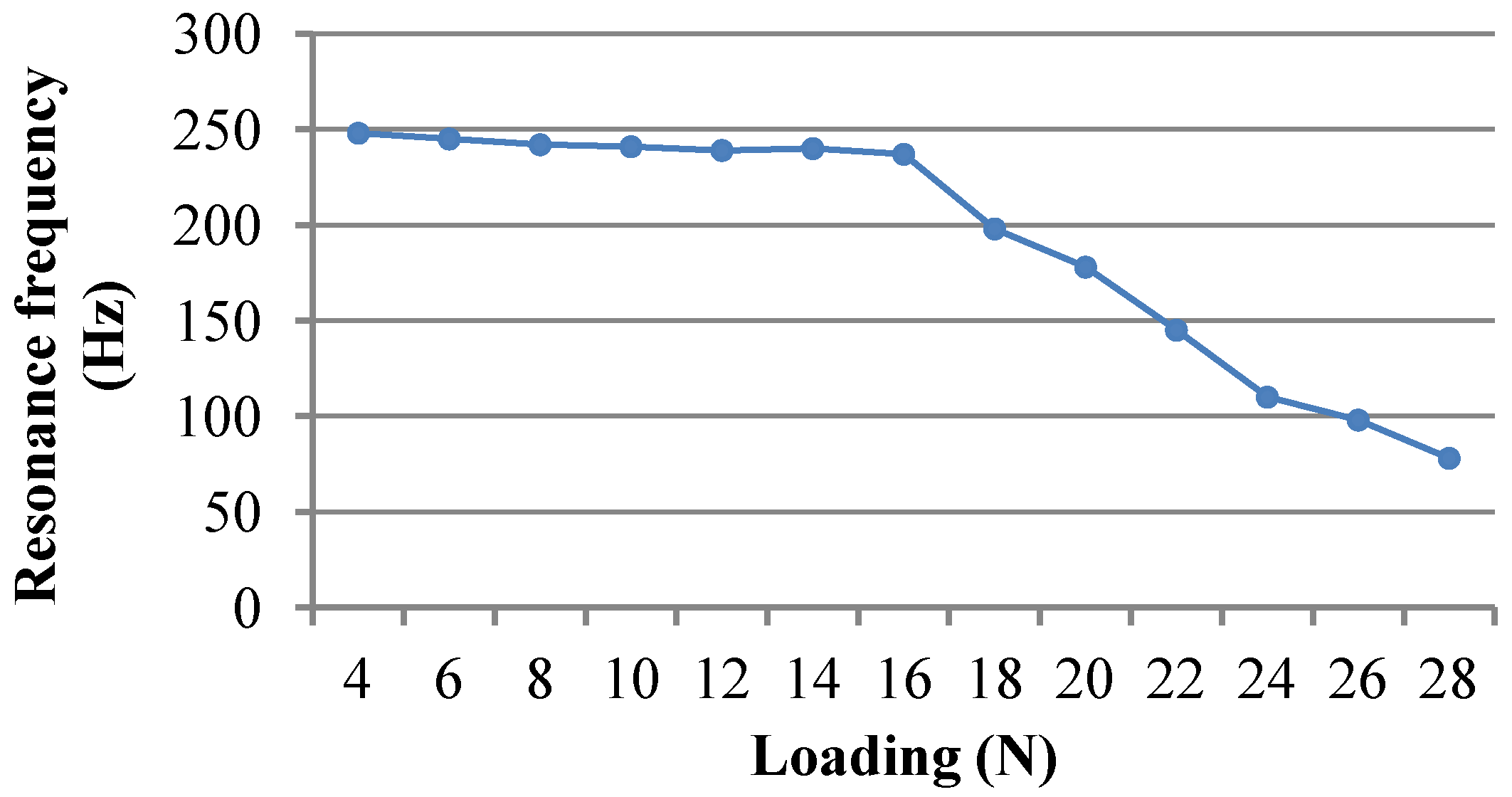
4.1. Experiment on Loading and System Resonance Frequency

The loading (material mass) and system resonance frequency of piezoelectric vibration feeder with magnetic spring relationship curve is shown in Figure 6, measured with the precise resistance analyzer while the feeder is working.
Figure 6. Relationship between loading and resonance frequency.
Micromachines 05 00547 g006
From the curve, as the loading is at 16 N and below, the prototype resonance frequency basically remains stable at 250 Hz. If the loading is above 16 N, the system resonance frequency dramatically reduces along with the increase of the loading. Therefore, the resonance frequency of the prototype is 250 Hz, and the maximum loading is 16 N.

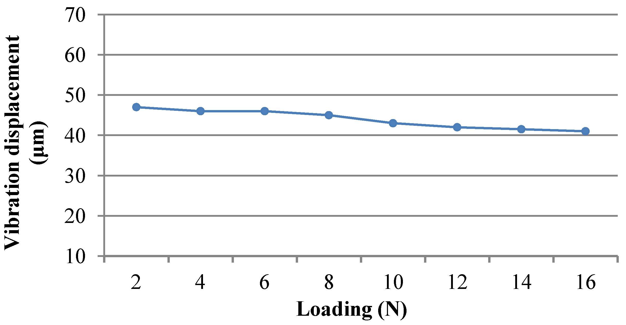
4.2. Experiment on the Relationship between System Loading and Vibration Displacement

Set the driving frequency at 250 Hz, loading increases gradually within 16 N. The loading and vibration displacement relationship is shown in Figure 7.
In the figure, as the loading increases, the vibration displacement decreases slowly, which means the prototype feeding speed reduces slowly.
Figure 7. Relationship between system loading and vibration displacement.
Micromachines 05 00547 g007

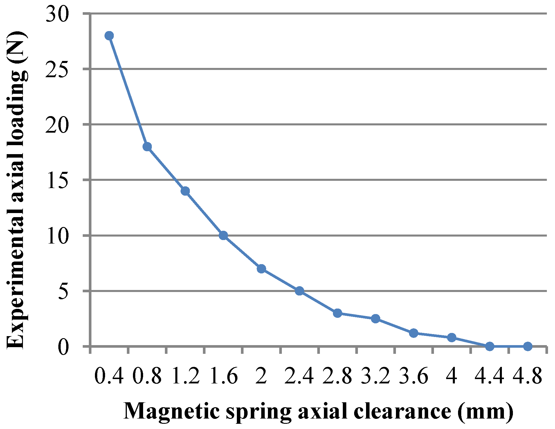
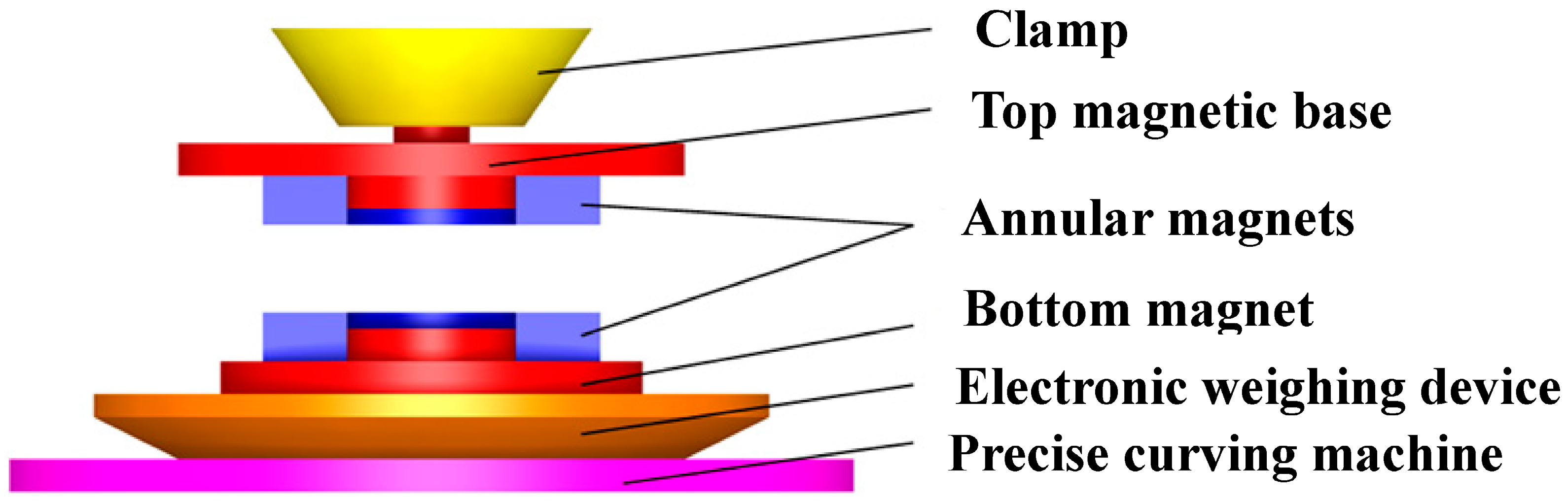
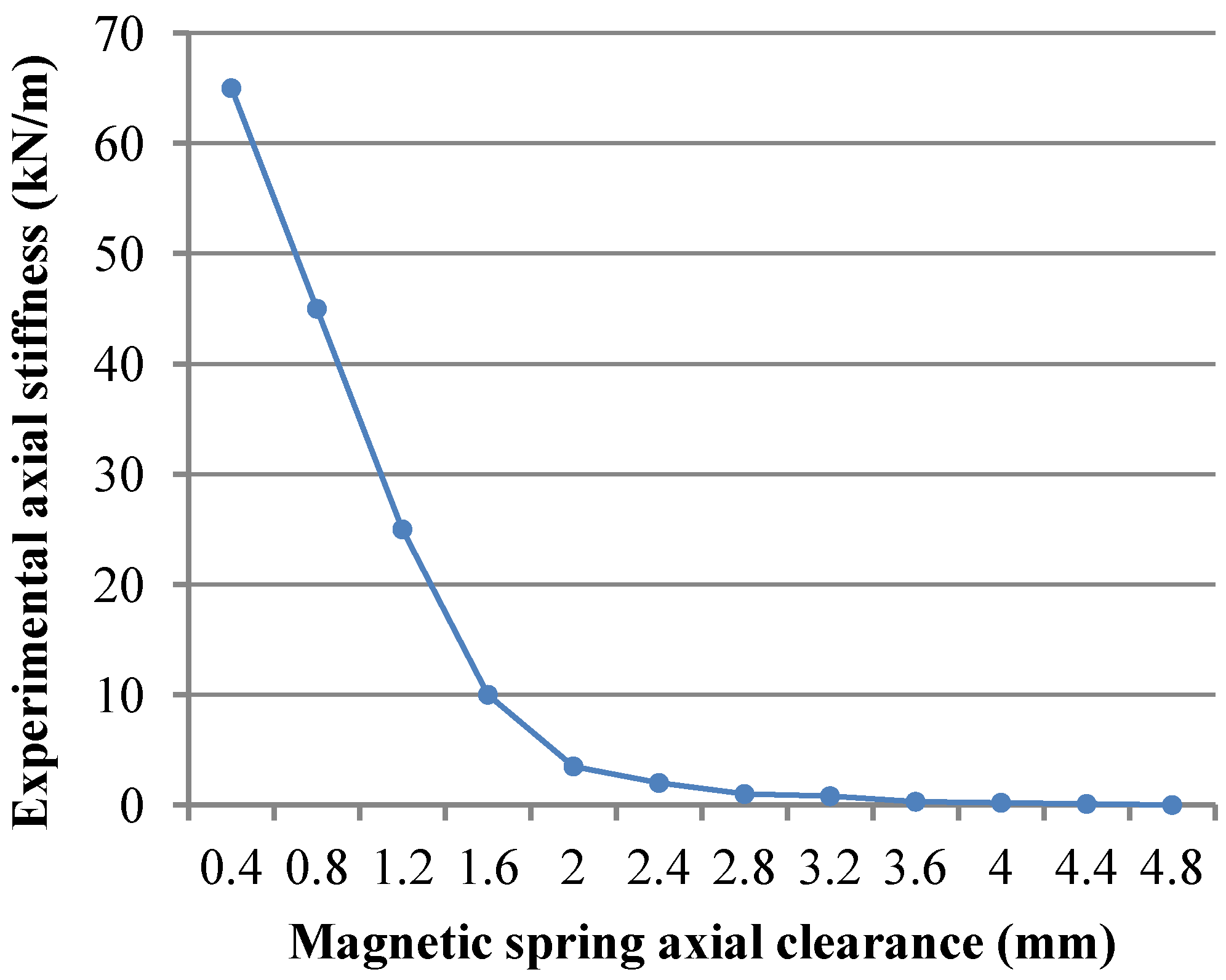
4.3. Experiment on Relationship among Magnetic Spring Loading, Stiffness and Axial Clearance

To validate the relationship among the magnetic spring stiffness, axial force and clearance, the magnetic spring axial force test is designed as is shown in Figure 8. The clearance, force and stiffness relationship is obtained, as is shown in Figure 9 and Figure 10. The electronic weighing device and precise carving machine are glued together, and the bottom magnetic base is glued to the electronic weighing device. One annular magnet is placed on the bottom magnetic base; and another annular magnet is placed on the top magnetic base. Keeping the two annular magnets with the same polarity facing each other, the tail of top magnetic base is fixed with the clamp in the precise carving machine. In this setup, the precise carving machine is like a three freedoms of degree precise movement platform in x, y and z directions, and the controlling accuracy is 0.003 mm. Moving the precise carving machine clamp in the x and y direction maintains the upper and lower magnets’ concentricity. Moving the z direction adjusts the axial clearance between the two magnets. The value from the electronic weighing device is the axial force between the two magnets.
Figure 8. The setup schematic diagram of magnetic spring experiment.
Micromachines 05 00547 g008
Figure 9. Relationship between loading and axial clearance of the magnetic spring.
Micromachines 05 00547 g009
Figure 10. Relationship between stiffness and axial clearance of the magnetic spring.
Micromachines 05 00547 g010

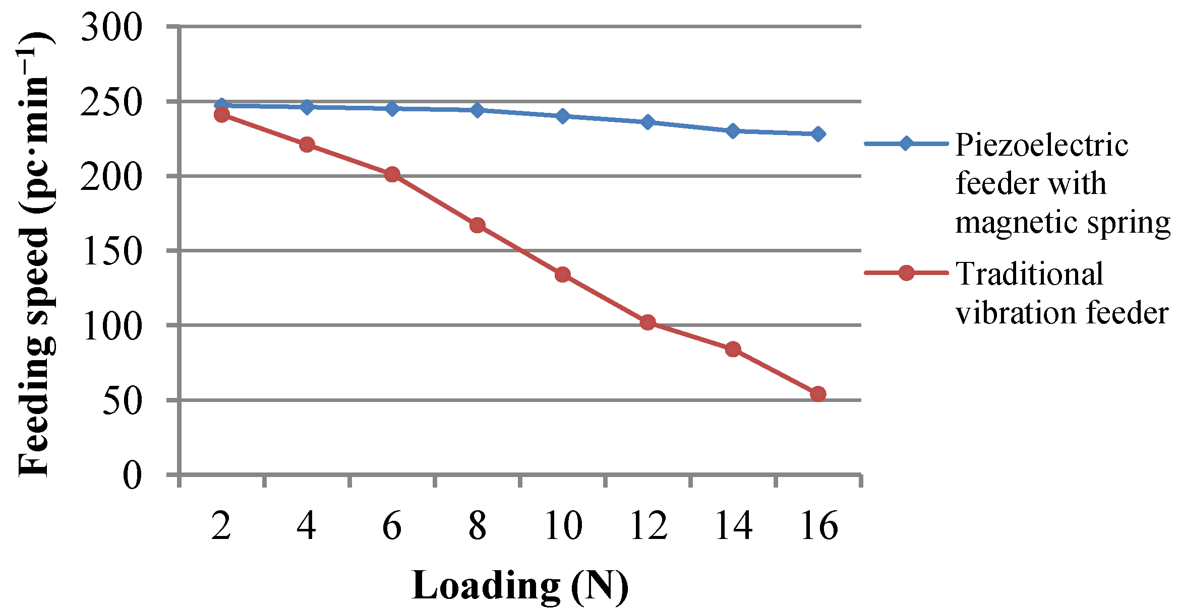
4.4. Contrast Experiment

We took the same size normal piezoelectric feeder, adjusted the signal generator, obtained voltage at 200 V, turned the frequency into resonance frequency at the loading 16 N and put the materials on the trays separately. Meanwhile, we changed the materials mass; two different feeding speeds were measured, as is shown in Figure 11. From the figure, as the loading increases, the normal spring feeder speed decreases rapidly. However, the prototype feeding speed decreases gradually within the nominal loading capacity (<16 N), which basically keeps the material feeding speed stable.
Figure 11. Loading-speed curve on different spring feeders.
Micromachines 05 00547 g011

5. Conclusions

Based on the theoretical analysis in the paper, when the load of the piezoelectric vibration feeder with magnetic spring has synchronous changes with the magnetic spring stiffness, the system resonance frequency has the possibility to become stable. The prototype experiment on the piezoelectric vibration feeder with magnetic spring has validated that, when the material mass changes, the magnetic spring stiffness also changes due to the axial clearance changes in the magnetic spring. Therefore, the prototype resonance frequency and the feeding speed changes are not obvious in some loading range, which makes it more stable compared with traditional feeders.

Acknowledgments

The work is funded by the National Science Foundation of China (51075175), which is named “Structure Design Theory and Performance Experimental Research of Piezoelectric driven high frequency Fatigue Testing Machine”.

Author Contributions

Yong Liu: responsible for the overall planning and task assignment, main composition and modification work in the paper. Xiaochao Tian: responsible for experiment, original data collection, composition of the paper draft. Zhigang Yang: instruct on the paper theory and experiment method. Yanhu Shen: responsible for deduction of the formula. Song Chen: responsible for figures and tables creation and prototype assembly.

Conflicts of Interest

The authors declare no conflict of interest

References

  1. Geoffrey, B. Xiong, Y.; Shan, C.; Lou, W., Translators; Assembly Automation and Product Design; China Machine Press: Beijing, China, 2009. [Google Scholar]
  2. Huang, X. Structure improvement of electromagnetic vibrating feeder. Met. Mine Des. Constr. 2001, 33, 21–24. (In Chinese) [Google Scholar]
  3. NTK Technical Ceramics. Piezoelectric Vibration Feeding Device. Japan Patent 52-61087, 4 May 1977. [Google Scholar]
  4. Ruich, K.; Takara, F. Piezoelectric driven and piezoelectric element vibration feeder. China Patent 1380234A, 20 November 2002. (In Chinese)[Google Scholar]
  5. Susumu, Y. Method and apparatus for controlling piezoelectric vibration. China Patent 1338668, 6 March 2002. (In Chinese)[Google Scholar]
  6. Maul, G.P.; Thomas, M.B. A system model and simulation of the vibratory bowl feeder. J. Manuf. Syst. 1997, 16, 309–314. [Google Scholar] [CrossRef]
  7. Ting, Y.; Shin, M.S.; Chang, H.Y. Analysis and design of four-bar linkage type vibratory parts feeder driven by piezoelectric actuator. In Proceeding of ASME 2002 International Design Engineering Technical Conferences and Computers and Information in Engineering Conference, Montreal, Canada, 29 September–2 October 2002; Volume 2, pp. 43–50.
  8. Choi, S.B.; Lee, D.H. Modal analysis and control of a bowl parts feeder activated by piezoelectric actuators. J. Sound Vib. 2004, 275, 452–458. [Google Scholar] [CrossRef]
  9. Chao, P.C.-P.; Chien, Y.-S. Dynamic modeling and experimental verification of a piezoelectric part feeder in a structure with parallel bimorph beams. Ultrasonics 2007, 46, 205–218. [Google Scholar] [CrossRef]
  10. Jiang, B.; Liu, X.L.; Yang, Z.G.; Tian, F.J.; Yu, Y. Study on vertical drive ultrasonic feeder. Opt. Precis. Eng. 2008, 16, 1082–1086. (In Chinese) [Google Scholar]
  11. Zhang, G.L.; Guo, H.; Zhao, C.S. Ultrasonic powder-feeding device and its application. J. Vib. Meas. Diagn. 2001, 21, 186–189. (In Chinese) [Google Scholar]
  12. Tian, Z.J.; Wu, W.F.; Han, F. The Experimental research on the floating piezoelectric vibratory feeder. Piezoelectrics Acoust. 2006, 28, 557–559. (In Chinese) [Google Scholar]
  13. Jiao, Q.W.; Cui, W.H.; Sun, B.Y.; He, C.Y. Research and produce of piezoelectric vibration feeder. Transducer Technol. 2001, 20, 23–26. (In Chinese) [Google Scholar]
  14. Tan, X.D.; Zhang, K. Mechanical analysis of the driven parts of piezoelectric vibration feeder. Manuf. Technol. Mach. Tool 2010, 3, 72–75. (In Chinese) [Google Scholar]
  15. Su, J.; Yang, Z.G.; Zhang, C.J.; Shen, Y.H. Line vibratory feeder driven by circular piezoelectric vibrator. Trans. Chin. Soc. Agric. Mach. 2013, 44, 289–292. (In Chinese) [Google Scholar]
  16. Li, Y.M. Research on a novel vibration bowel feeder and control system. Master’s Thesis, Tianjin University, 25 May 2005. [Google Scholar]
  17. Su, J.; Yang, Z.G.; Tian, F.G.; Shen, Y.H. Inertial piezoelectric vibratory feeder. Trans. Chin. Soc. Agric. Mach. 2013, 44, 281–286. (In Chinese) [Google Scholar]
  18. Qian, K.X.; Lu, L.C.; Ru, W.M.; Zheng, M.; Ma, L.Z. A magnetic spring and its elasticity. Chin. J. Mech. Eng. 1998, 34, 57–59. (In Chinese) [Google Scholar]
  19. Cai, C.C.; Xu, Z.F.; Zhuang, J.P.; Yu, H. The analysis of working property for magnetic spring. Equip. Des. Maint. 2003, 6, 73–74. (In Chinese) [Google Scholar]
  20. Yang, H.; Zhao, H. Study on dynamic characters of rare earth permanent magnetic spring. Trans. Chin. Soc. Agric. Mach. 2003, 34, 111–117. (In Chinese) [Google Scholar]

