Adaptive Liquid Lens Actuated by Droplet Movement

School of Electronics and Information Engineering, Sichuan University, Chengdu 610065, China
*
Author to whom correspondence should be addressed.
Micromachines 2014, 5(3), 496-504; https://doi.org/10.3390/mi5030496
Submission received: 5 June 2014
/
Revised: 22 July 2014
/
Accepted: 29 July 2014
/
Published: 4 August 2014
(This article belongs to the Special Issue Microlenses)
Abstract
:In this paper we report an adaptive liquid lens actuated by droplet movement. Four rectangular PMMA (Polymethyl Methacrylate) substrates are stacked to form the device structure. Two ITO (Indium Tin Oxide) sheets stick on the bottom substrate. One PMMA sheet with a light hole is inserted in the middle of the device. A conductive droplet is placed on the substrate and touches the PMMA sheet to form a small closed reservoir. The reservoir is filled with another immiscible non-conductive liquid. The non-conductive liquid can form a smooth concave interface with the light hole. When the device is applied with voltage, the droplet stretches towards the reservoir. The volume of the reservoir reduces, changing the curvature of the interface. The device can thus achieve the function of an adaptive lens. Our experiments show that the focal length can be varied from −10 to −159 mm as the applied voltage changes from 0 to 65 V. The response time of the liquid lens is ~75 ms. The proposed device has potential applications in many fields such as information displays, imaging systems, and laser scanning systems.
1. Introduction
Adaptive microlens has received considerable attention for the wide range of applications such as information displays, cameras, laser scanning systems, and wavefront distortion compensation. According to the difference of the filled materials, it can be roughly classified into two categories: liquid crystal (LC) lens [1,2,3,4,5] and liquid lens [6,7,8,9,10,11,12,13,14,15,16,17,18,19,20,21,22,23,24]. An adaptive LC lens usually employs an inhomogeneous electric field to make the LC molecules reorient to produce a gradient refractive index profile. The LC lens is polarization-dependent which means that the lens has low spectral transmission. Since the response time depends on the LC layer thickness and the size of the LC lens, it is more suitable for making microlens which constrains the real applications in imaging systems. There are three common operating mechanisms to design a liquid lens: electrowetting effect [6,7,8,9,10,11,12,13,14], dielectric force [15,16,17,18], and fluidic pressure [19,20,21,22,23,24].
A dielectric lens uses two non-conductive liquids of different dielectric constants to form a smooth liquid-liquid interface. It can bear high operating voltage and has lower power consumption. However, the dielectric lens needs be applied with inhomogeneous electric field. So the electrodes of the dielectric lens should be etched with holes or rings which make the device fabrication more complicated. A fluidic pressure based liquid lens usually makes use of a PDMS (polydimethylsiloxane) membrane to control the volume of the liquids. The membrane lens can achieve a large lens aperture and the focal length can be varied within a wide range. However, the disadvantages of this type of lens cannot be ignored. For example, the gravity effect may exist in the membrane lens when it is placed in vertical position, which may degrade the imaging performance. By applying an external driving system, the lens would have a bulk volume and high power consumption. Compared with the liquid lens discussed above, electrowetting-based liquid lens has the advantages of polarization independent, fast response, and simple fabrication.
In this paper we demonstrate an adaptive liquid lens actuated by droplet movement. Compared with other adaptive liquid lenses, our lens has the competitive advantages in simple structure, reasonably fast response time and low power consumption. In our device, the volume change of the reservoir is actuated by liquid pressure. So it is possible to significantly actuate a large-aperture lens or microlens array at a relatively low operating voltage. Furthermore, the proposed lens can maintain a better liquid interface compared with the lens whose electrode structure is rings [14,15]. Because the rings-shape electrode could cause the different frictions for the droplet, the curvature of the lens would be nonuniform. One experiments show that the focal length can be varied from −10 to −159 mm as the applied voltage changes from 0 to 65 V. The response time of the liquid lens is ~75 ms.
2. Device Mechanism and Fabrication
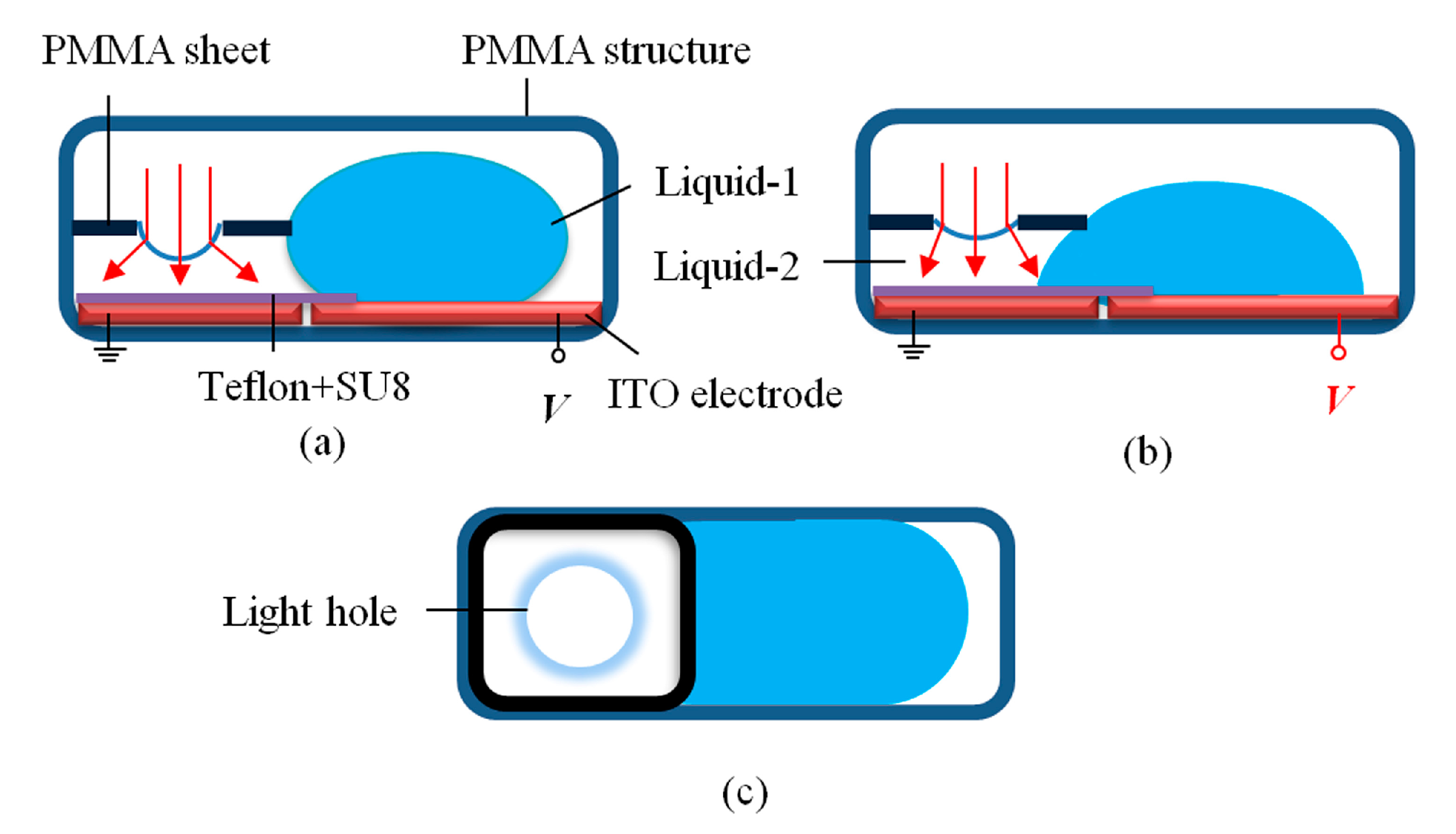
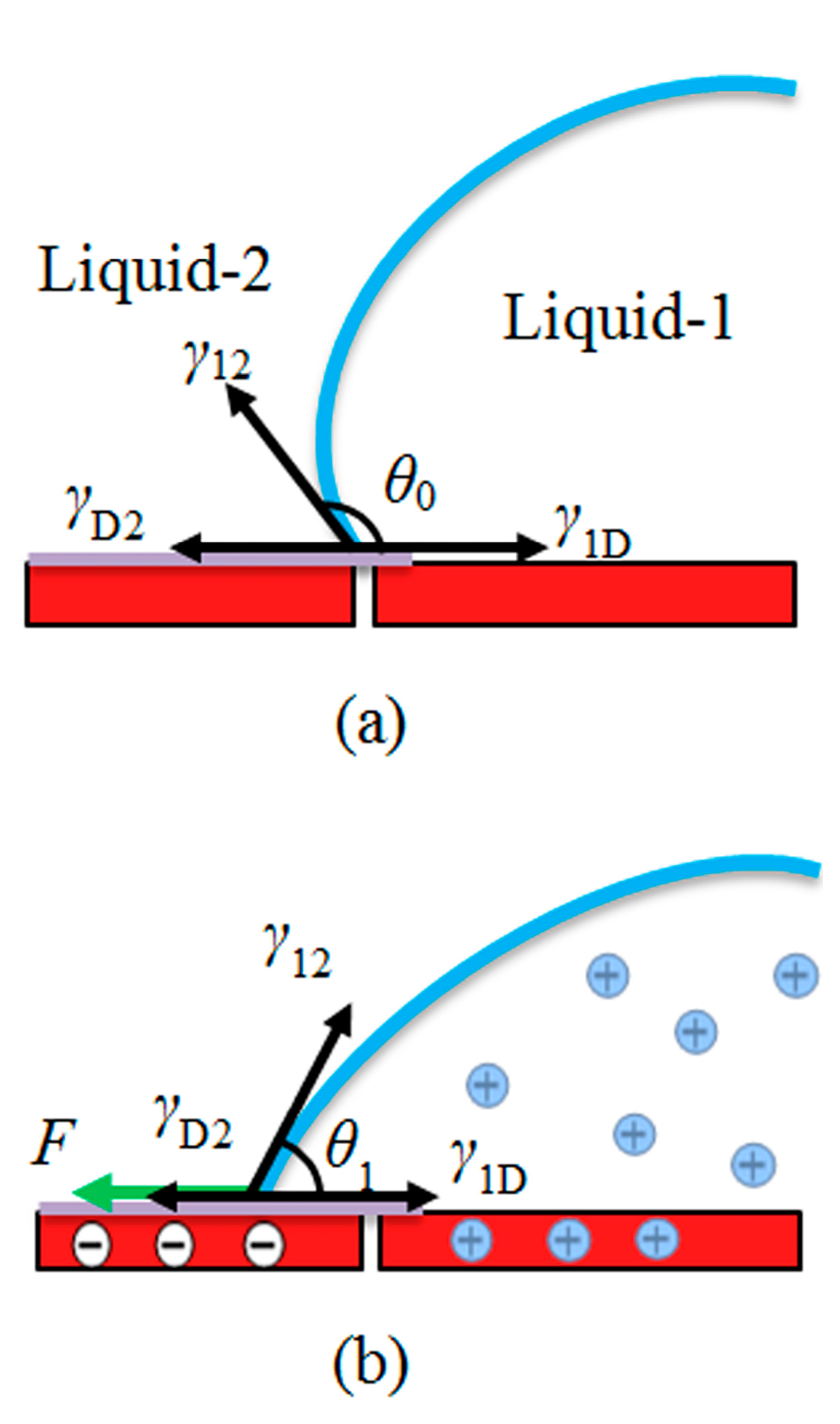
Figure 1 shows the schematic of the proposed device and the operation mechanism. Two ITO sheets are fabricated on the bottom substrate. The left-ITO sheet is coated with a dielectric layer whose dielectric constant is ~3.5. A PMMA sheet with a light hole is inserted in the middle of the PMMA structure. A conductive droplet (Liquid-1) is placed on the substrate and its left side touches the PMMA sheet to form a closed reservoir. Then we inject another immiscible non-conductive liquid (Liquid-2) from the light hole. The droplet touches the PMMA sheet and completely seals the right-hand side of the device. The space of the oil phase is just like a reservoir. The droplet extrudes the reservoir to make a liquid pressure. When the droplet moves towards the left side of the device, the volume of the oil phase can be changed. That is to say, the volume of the oil phase determines the range of achievable focal lengths. At initial state, the non-conductive liquid can form a smooth concave surface, as shown in Figure 1a. In this state, the light beam is divergent when it passes through the device. When we apply voltage V to the right-ITO sheet, the droplet stretches towards the reservoir due to electrowetting effect, making its volume decrease. So the curvature of the interface is changed, as shown in Figure 1b. The top view of the device is also depicted in Figure 1c. Figure 2 shows the electrowetting effect mechanism in the device. At initial state, as shown in Figure 2a, the balance of the interface between Liquid-1, Liquid-2 and the dielectric layer tri-junction line is governed by the equations as below [25]:
![Micromachines 05 00496 i001]() where θ0 is the initial contact angle without applied voltage, θ1 is the contact angle when voltage is applied to the device, U is the external voltage to the ITO sheet, d is the thickness of the dielectric insulator, ε = ε0εr is the dielectric constant of the dielectric insulator, γ12 is the surface tension between Liquid-1 and Liquid-2, γ1D is the surface tension between Liquid-1 and dielectric insulator, and γD2 is the surface tension between dielectric insulator and Liquid-2. When the external force is applied to the droplet reaches to balance, as shown in Figure 2b, the droplet satisfies the following equation:
where F represents the electric force of per meter.
where θ0 is the initial contact angle without applied voltage, θ1 is the contact angle when voltage is applied to the device, U is the external voltage to the ITO sheet, d is the thickness of the dielectric insulator, ε = ε0εr is the dielectric constant of the dielectric insulator, γ12 is the surface tension between Liquid-1 and Liquid-2, γ1D is the surface tension between Liquid-1 and dielectric insulator, and γD2 is the surface tension between dielectric insulator and Liquid-2. When the external force is applied to the droplet reaches to balance, as shown in Figure 2b, the droplet satisfies the following equation:
where F represents the electric force of per meter.

γD2 + γ12 cosθ0 = γ1D
F + γD2 = γ12 cosθ1 + γ1D
To fabricate the device shown in Figure 1, four PMMA substrates are stacked to form the structure using glue UV-331. The whole size of the structure is 15 mm × 8 mm × 8 mm. First, two ITO sheets with the size of 8 mm × 7 mm are made on the bottom substrate and the gap between them is 0.5 mm. The left-ITO sheet is coated with a SU8 layer (~1 µm) as an insulator, followed by a thin Teflon layer (AF-1600, from DuPont, Wilmington, DE, USA). The surface tension of the Teflon layer is ~18 mN·m−1 at 20 °C. Then a PMMA sheet is inserted in the middle of the device. The size of the PMMA sheet is 8 mm × 7 mm and the diameter of the light hole is 3 mm. Next, we place a droplet of NaCl solution (Liquid-1: the density is 1.05 g·cm−3, viscosity is ~12 mPa s at room temperature) on the substrate and filled the channel, as shown in Figure 1c. Finally, the silicon oil (Liquid-2: the density is 0.98 g·cm−3, surface tension is ~19 mN·m−1 at 20 °C, viscosity is ~10 mPa s at room temperature, refractive index is 1.40) is injected from the light hole.
Figure 1.
Schematic of the proposed device and the operation mechanism: (a) Initial state; (b) Applied voltage to the device; (c) Top view of the device.
Figure 1.
Schematic of the proposed device and the operation mechanism: (a) Initial state; (b) Applied voltage to the device; (c) Top view of the device.

Figure 2.
Electrowetting effect mechanism in the device: (a) Initial state; (b) External force reaching to balance.
Figure 2.
Electrowetting effect mechanism in the device: (a) Initial state; (b) External force reaching to balance.

3. Experiment and Discussion
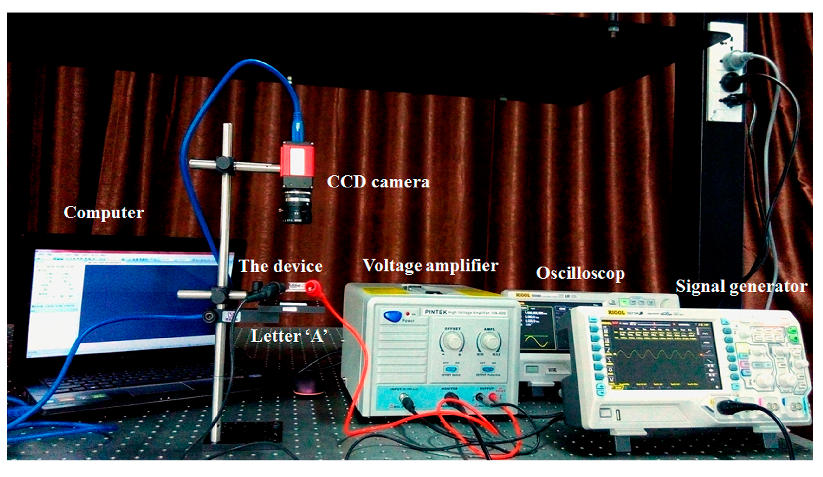
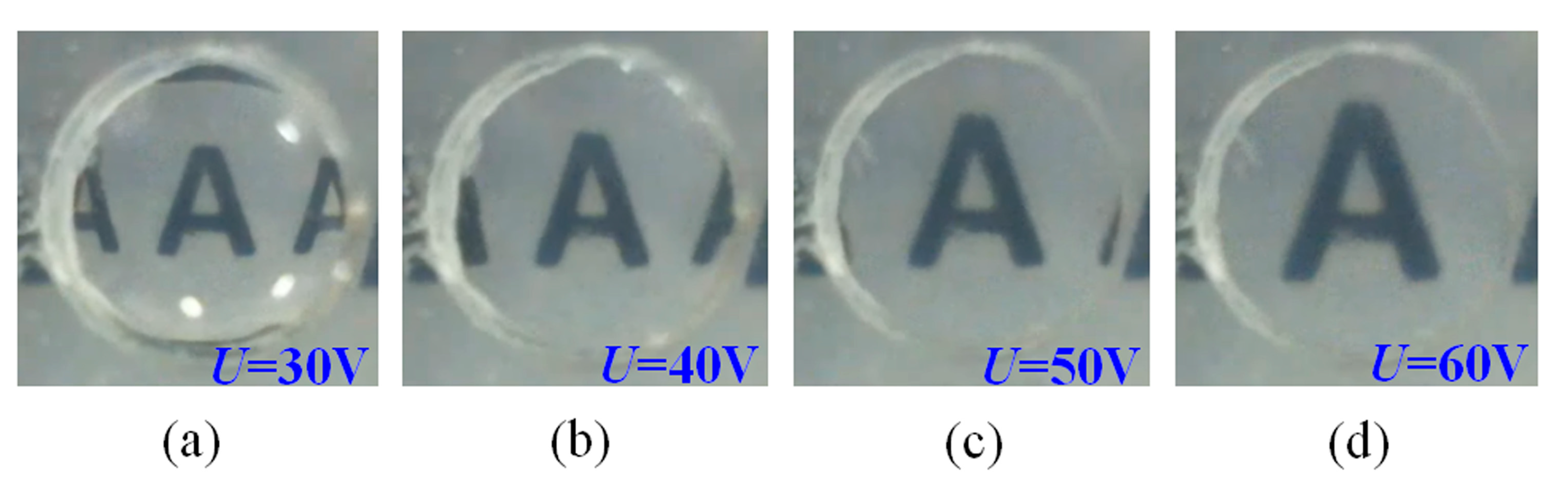
To evaluate the device performance during actuation process, we recorded the image of an object through the lens. The optical setup is shown in Figure 3. We placed a printed letter “A” 5 mm below the device; thus, the object was always within the focal length of the lens. Therefore, we can observe an upright virtual image. A CCD (charge coupled device) camera was used to record the image-change. When we applied voltage U < 30 V to the device, the droplet could not move. The liquid lens has the shortest negative focal length, as shown in Figure 4a. When the voltage 30 V < U < 65 V, the droplet started to move towards the reservoir, the image-change was shown in Figure 4b–d. When the voltage U = 65 V, the magnification reached maximum. When we removed the external voltage, the droplet moved backwards to its original position automatically due to the high interface tension with the sidewall of the structure.
Figure 3.
Optical setup of the device.

Figure 4.
Images for different focal lengths under different voltages: (a) Initial state; (b) State 1; (c) State 2; (d) State 3.
Figure 4.
Images for different focal lengths under different voltages: (a) Initial state; (b) State 1; (c) State 2; (d) State 3.
To measure the focal length of the liquid lens, we expanded and collimated a He-Ne laser beam (λ = 632.8 nm) to ~3 mm in diameter and let it normally pass through the liquid lens. The focal length is determined by a geometrical imaging method, as shown in Figure 5a. So f = (d2 − d1) × l1/(l2 − l1) − d1. Every measurement was repeated three times and the results were averaged. In our experiment, the focal length can be changed from −10 to −159 mm with the voltage changing from 0 to 65 V. As we can see from Figure 5b, the focal length changes differently between voltage-on state and voltage-off state. The main reason for this may be explained as follows: regarding the droplet movement, it is more difficult to extrude the reservoir than move freely backward to its original position. Furthermore, the frictional force between the droplet and the structure may be changed several times after the droplet movement on the substrate.
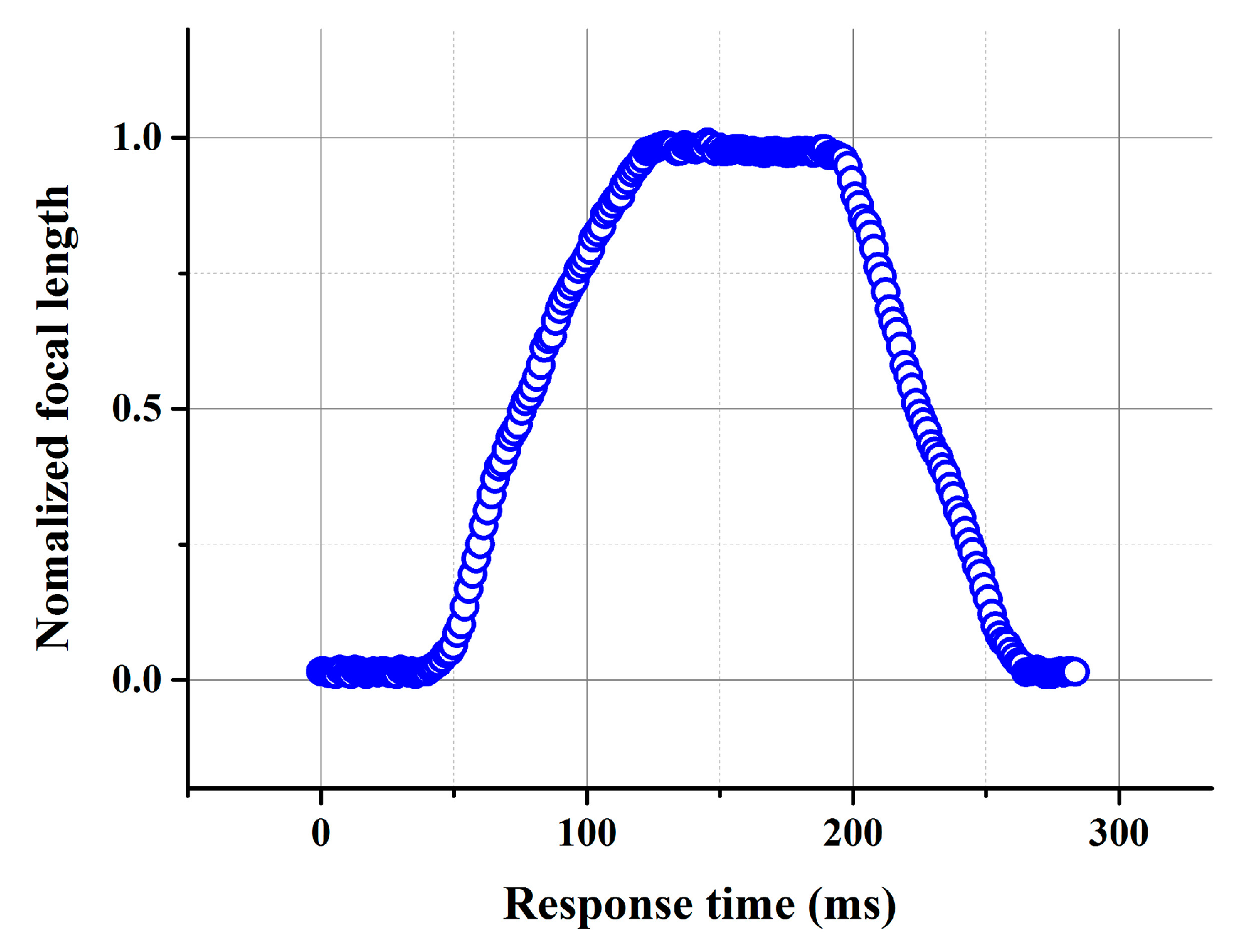
Response time is another key point to measure the optical performance of the device. We take the absolute value of the focal length and normalize it. Figure 6 shows the response time of the device. As we can see, it takes a time of ~75 ms (~63 ms) for the device changing the focal length from −10 (−159) to −159 mm (−10 mm). The device has a relatively fast response time.
Figure 5.
Protocol adopted for the determination of focal length (a) and focal length versus applied voltage (b).
Figure 5.
Protocol adopted for the determination of focal length (a) and focal length versus applied voltage (b).
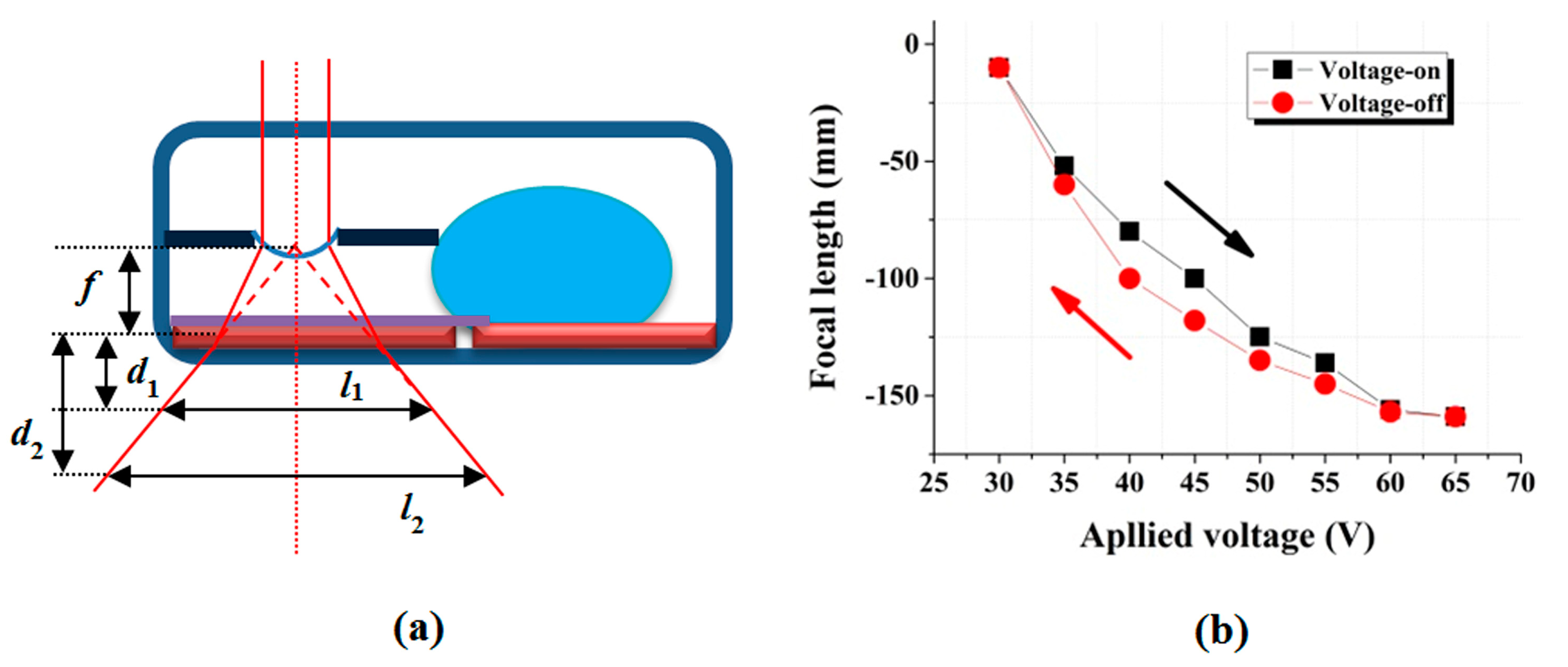
Figure 6.
Response time of the device (U = 65 V).
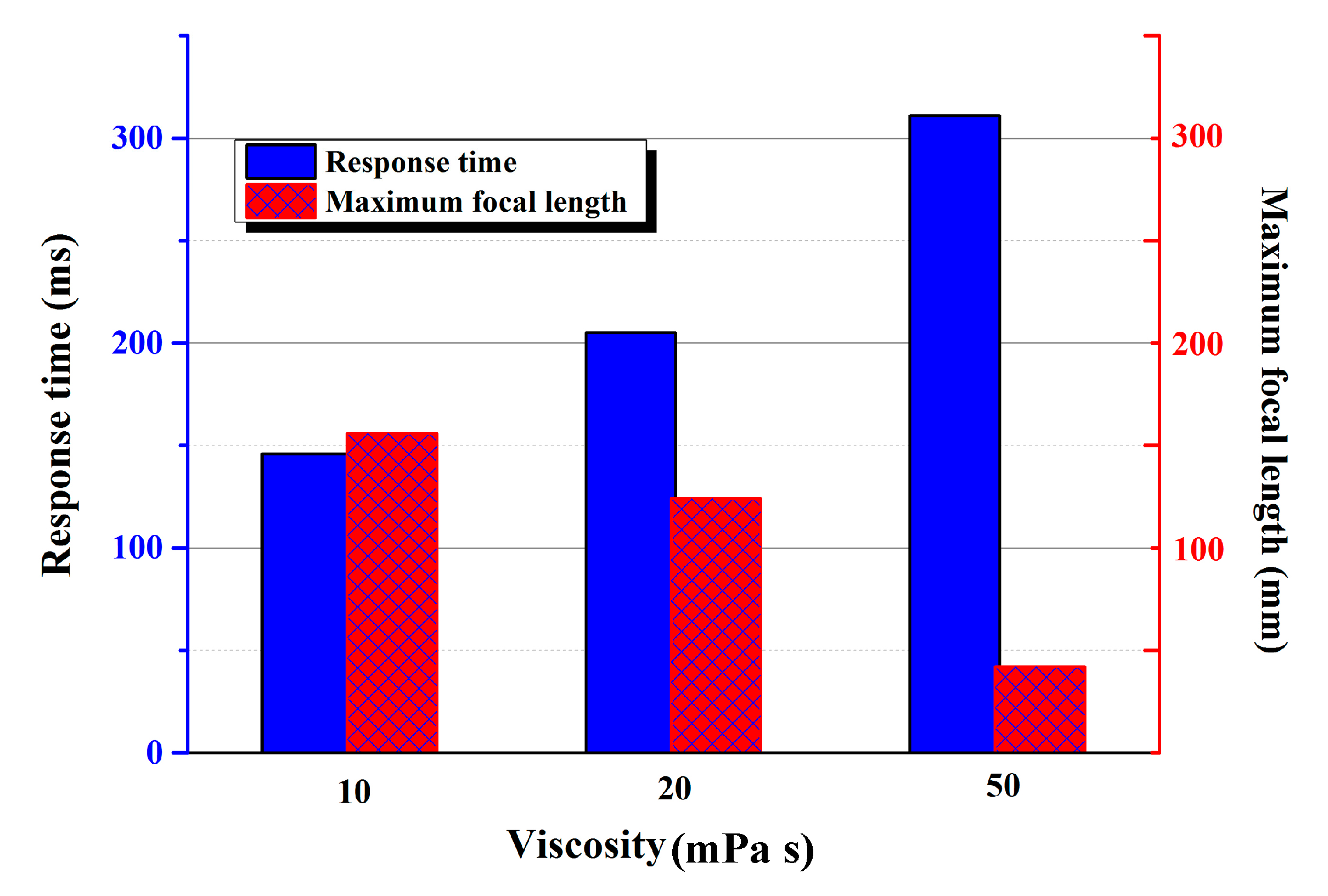
Liquid viscosity plays a significant role in response time of a device. First we define the total response time as the sum of the rise time and descend time. We did another experiment at the voltage of 60 V to study the relationship between the liquid viscosity and the total response time. In the experiment, we choose three silicone oils with different viscosities (10 mPa s, 20 mPa s, and 50 mPa s) as Liquid-2, respectively. Liquid-1 remained the same. The measured response time of different liquids are 146 ms, 205 ms, and 311 ms, respectively. The measured maximum focal lengths are 156 mm, 124 mm, and 42 mm, respectively. As shown in Figure 7, the response time prolongs as the viscosity increases. Thus, the viscosity of the oil plays a significant role in changing the focal length of the liquid lens, as shown in Figure 7. High liquid viscosity means low flow ability. So the movement of Liquid-1 will be restrained, which leads to the decrease of the maximum focal length.
Figure 7.
Response time and the maximum focal length under different liquid viscosities.
The curvature of the interface of the proposed adaptive liquid lens cannot change from concave surface to convex surface which constrains the varied range of the focal length. The main reason is that in our device the droplet actuated by electrowetting extrudes the reservoir to make a liquid pressure. In the experiment, the electrostatic force is not large enough to make the droplet move a relatively long distance towards the PMMA sheet. So the volume change of the reservoir is limited. Thus, the configuration of the lens cannot change from divergent to convergent. If we decrease the thickness of the dielectric layer and the whole size of the device, the device can obtain a robust optical performance. We can also increase the external voltage to solve this issue. However, the high applied voltage will decrease the lifetime of the device. So we should choose the proper voltage and carefully design the device. Our device also suffers from gravity effect when placed in vertical position. We can choose three immiscible density-matched liquids filled with the device to solve this issue. This will form the basis for our further work.
4. Conclusions
In this paper we reported an adaptive liquid lens actuated by droplet movement. The device is fabricated with four rectangular PMMA substrates. Two ITO sheets are stacked on the bottom substrate with a small gap between them. One sheet with a light hole is inserted in the middle of the device. A conductive droplet touches the sheet to form a small closed reservoir which is filled with another immiscible non-conductive liquid. When we apply a DC (direct current) voltage to the device, the droplet stretches towards the reservoir making the curvature of the interface changed. Our experiments show that the focal length can be varied from −10 to −159 mm as the applied voltage changes from 0 to 65 V. The response time of the liquid lens is ~75 ms. The proposed device has potential applications such as information displays, cameras, imaging systems and laser scanning systems.
Acknowledgments
The work is supported by the NSFC under Grant Nos. 61225022 and 61320106015, the “973” Program under Grant No. 2013CB328802, and the “863” Program under Grant Nos. 2012AA011901 and 2012AA03A301.
Author Contributions
Study concepts, design experimental studies, manuscript editing: Chao Liu. Data acquisition, analysis, interpretation, statistical analysis: Li-Xiao Yao and Ming-Huan Wang. Manuscript revision, review, final version approval: Qiong-Hua Wang.
Conflicts of Interest
The authors declare no conflict of interest.
References
- Xu, M.; Zhou, Z.W.; Ren, H.; Lee, S.H.; Wang, Q.H. Tunable liquid microlens. J. Appl. Phys. 2013, 113. [Google Scholar] [CrossRef]
- Wang, B.; Ye, M.; Sato, S. Liquid crystal lens with focal length variable from negative to positive values. IEEE Photonics Technol. Lett. 2006, 18, 79–81. [Google Scholar] [CrossRef]
- Hwang, S.J.; Liu, Y.X.; Porter, G.A. Tunable liquid crystal microlenses with crater polymer prepared by droplet evaporation. Opt. Express 2013, 21, 30731–30738. [Google Scholar] [CrossRef]
- Ren, H.; Xu, S.; Wu, S.T. Polymer-stabilized liquid crystal microlens array with large dynamic range and fast response time. Opt. Lett. 2013, 38, 3144–3147. [Google Scholar] [CrossRef]
- Ye, M.; Wang, B.; Sato, S. Liquid-crystal lens with a focal length that is variable in a wide range. Appl. Opt. 2004, 43, 6407–6412. [Google Scholar] [CrossRef]
- Bergea, B.; Peseux, J. Variable focal lens controlled by an external voltage: An application of electrowetting. Eur. Phys. J. E. 2000, 3, 159–163. [Google Scholar] [CrossRef]
- Peng, R.; Wang, D.Z.; Hu, Z.W.; Chen, J.B.; Zhuang, S.L. Focal length hysteresis of a double-liquid lens based on electrowetting. J. Opt. 2013, 15. [Google Scholar] [CrossRef]
- Kuipera, S.; Hendriks, B.H.W. Variable-focus liquid lens for miniature cameras. Appl. Phys. Lett. 2004, 99. [Google Scholar] [CrossRef]
- Krupenkin, T.; Yang, S.; Mach, P. Tunable liquid microlens. Appl. Phys. Lett. 2003, 82, 316–318. [Google Scholar] [CrossRef]
- Grilli, S.; Miccio, L.; Vespini, V.; Finizio, A.; Nicola, S.D.; Ferraro, P. Liquid micro-lens array activated by selective electrowetting on lithium niobate substrates. Opt. Express 2008, 16, 8084–8093. [Google Scholar] [CrossRef]
- Murade, C.U.; Ende, D.V.D.; Mugele, F. High speed adaptive liquid microlens array. Opt. Express 2012, 20, 18180–18187. [Google Scholar] [CrossRef]
- Choi, H.; Won, Y. Fluidic lens of floating oil using round-pot chamber based on electrowetting. Opt. Lett. 2013, 38, 2197–2199. [Google Scholar] [CrossRef]
- Li, C.H.; Jiang, H.R. Electrowetting-driven variable-focus microlens on flexible surfaces. Appl. Phys. Lett. 2012, 100. [Google Scholar] [CrossRef]
- Liu, C.X.; Park, J.; Choi, J.W. A planar lens based on the electrowetting of two immiscible liquids. J. Micromech. Microeng. 2008, 18. [Google Scholar] [CrossRef]
- Cheng, C.C.; Yeh, J.A. Dielectrically actuated liquid lens. Opt. Express 2007, 15, 7140–7145. [Google Scholar] [CrossRef]
- Ren, H.; Xianyu, H.; Xu, S.; Wu, S.T. Adaptive dielectric liquid lens. Opt. Express 2008, 16, 14954–14960. [Google Scholar]
- Tsai, C.G.; Chen, C.N.; Cheng, L.S.; Cheng, C.C.; Yang, J.T.; Yeh, J.A. Planar liquid confinement for optical centering of dielectric liquid lenses. IEEE Photonics Technol. Lett. 2009, 21, 1396–1398. [Google Scholar] [CrossRef]
- Yang, C.C.; Tsai, C.G.; Yeh, J.A. Dynamic behavior of liquid microlenses actuated using dielectric force. J. Microelectromech. Syst. 2011, 20, 1143–1149. [Google Scholar] [CrossRef]
- Li, L.; Wang, Q.H.; Jiang, W. Liquid lens with double tunable surfaces for large power tunability and improved optical performance. J. Opt. 2011, 13. [Google Scholar] [CrossRef]
- Xu, S.; Ren, H.; Wu, S.T. Adaptive liquid lens actuated by liquid crystal pistons. Opt. Express 2012, 20, 28518–28523. [Google Scholar] [CrossRef]
- Moran, P.M.; Dharmatilleke, S.; Khaw, A.H.; Tan, K.W.; Chan, M.L.; Rodrigueza, I. Fluidic lenses with variable focal length. Appl. Phys. Lett. 2006, 88. [Google Scholar] [CrossRef]
- Mao, X.; Stratton, Z.I.; Nawaz, A.A.; Lin, S.C.S.; Huang, T.J. Optofluidic tunable microlens by manipulating the liquid meniscus using a flared microfluidic structure. Biomicrofluidics 2010, 4. [Google Scholar] [CrossRef]
- Dong, L.; Agarwal, A.K.; Beebe, D.J.; Jiang, H. Adaptive liquid microlenses activated by stimuli-responsive hydrogels. Nature 2006, 442, 551–554. [Google Scholar] [CrossRef]
- Song, C.L.; Nguyen, N.T.; Asundi, A.K.; Low, C.L.N. Biconcave micro-optofluidic lens with low-refractive-index liquids. Opt. Lett. 2009, 34, 3622–3624. [Google Scholar] [CrossRef]
- Mugele, F.; Baret, J.C. Electrowetting: From basics to applications. J. Phys Condens. Matter. 2005, 17, R705–R774. [Google Scholar] [CrossRef]
© 2014 by the authors; licensee MDPI, Basel, Switzerland. This article is an open access article distributed under the terms and conditions of the Creative Commons Attribution license (http://creativecommons.org/licenses/by/3.0/).
Share and Cite
MDPI and ACS Style
Liu, C.; Wang, Q.-H.; Yao, L.-X.; Wang, M.-H. Adaptive Liquid Lens Actuated by Droplet Movement. Micromachines 2014, 5, 496-504. https://doi.org/10.3390/mi5030496
AMA Style
Liu C, Wang Q-H, Yao L-X, Wang M-H. Adaptive Liquid Lens Actuated by Droplet Movement. Micromachines. 2014; 5(3):496-504. https://doi.org/10.3390/mi5030496
Chicago/Turabian StyleLiu, Chao, Qiong-Hua Wang, Li-Xiao Yao, and Ming-Huan Wang. 2014. "Adaptive Liquid Lens Actuated by Droplet Movement" Micromachines 5, no. 3: 496-504. https://doi.org/10.3390/mi5030496