Article

A Peristaltic Pump Integrated on a 100% Glass Microchip Using Computer Controlled Piezoelectric Actuators

Quantitative Biology Center (QBiC), RIKEN, 2-2-3 Minatojima-minamimachi, Chuo, Kobe, Hyogo 650-0047, Japan
Micromachines 2014, 5(2), 289-299; https://doi.org/10.3390/mi5020289
Submission received: 14 March 2014 / Revised: 2 May 2014 / Accepted: 20 May 2014 / Published: 23 May 2014
(This article belongs to the Special Issue Micropumps: Design, Fabrication and Applications)

Abstract

:
Lab-on-a-chip technology is promising for the miniaturization of chemistry, biochemistry, and/or biology researchers looking to exploit the advantages of a microspace. To manipulate fluid on a microchip, on-chip pumps are indispensable. To date, there have been several types of on-chip pumps including pneumatic, electroactive, and magnetically driven. However these pumps introduce polymers, metals, and/or silicon to the microchip, and these materials have several disadvantages, including chemical or physical instability, or an inherent optical detection limit. To overcome/avoid these issues, glass has been one of the most commonly utilized materials for the production of multi-purpose integrated chemical systems. However, glass is very rigid, and it is difficult to incorporate pumps onto glass microchips. This paper reports the use of a very flexible, ultra-thin glass sheet (minimum thickness of a few micrometers) to realize a pump installed on an entirely glass-based microchip. The pump is a peristaltic-type, composed of four serial valves sealing a cavity with two penetrate holes using ultra-thin glass sheet. By this pump, an on-chip circulating flow was demonstrated by directly observing fluid flow, visualized via polystyrene tracking particles. The flow rate was proportional to the pumping frequency, with a maximum flow rate of approximately 0.80 μL/min. This on-chip pump could likely be utilized in a wide range of applications which require the stability of a glass microchip.

Graphical Abstract

1. Introduction

Miniaturization in chemistry or biology to generate so-called “lab-on-a-chip” technology or micro total analysis systems (μ-TAS) has generated substantial interest due to reduced consumption of reagents, space requirements and analysis times [1]. Exploiting these advantages, many researchers have developed novel methodologies to use microdevices for chemical and biochemical analysis and syntheses [2,3]. However, to dramatically decrease the amount of reagent used, an on-chip pump would be very useful.
There have been various types of on-chip pumps reported [4,5]. From the viewpoint of driving source, piezoelectric actuator has been frequently used [6,7,8]. Silicon, metal, or polymer components are the most common materials used in these pumps. Especially recently, polymer-based tubular [9] and diaphragm [10] pumps have frequently been used in this field because of their flexibility, light weight, and low cost characteristics. Similarly, on-chip peristaltic pumps, pneumatic valves, and pumps that exploit the flexible elastomeric properties of polydimethylsiloxane (PDMS) [11,12] have become a standard way of on-chip fluid manipulation, because PDMS is very reasonable and easily fabricated. Large-scale integration [13,14] and piezoelectric types [15,16] have also been reported. Although those pumps are quite sophisticated and convenient to use, there are several disadvantages to their use, including chemical and physical instability, as well as and narrow detection limits, which are a function of optical transparency.
In contrast, glass-based microchips have been developed and used for multi-purpose integration in chemical and biochemical operations [2] in which the chemical stability of glass against organic solvents and gases and its optical transparency are effectively exploited. A number of applications such as optical detection, organic synthesis [17] gas analysis systems [18], adhesive cell patterning and culturing [19], biomolecule separations [20,21,22], and biological analysis systems [23] have been developed which were difficult to realize using traditional polymer microchips. However, glass is very rigid. This fact makes it difficult to install pumps on a glass microchip.
Although several polymers including Parylene [24], Teflon [25], or polyimide [26] are relatively chemically inert and used in microchip materials, they still have high permeability as compared to glass, or are not optically transparent. Recently, glass coating methods with PDMS microchannels were developed in order to generate chemical stability [27], but these methods are difficult to apply to actuating parts. Circulating flow in a glass microchip using the shear stress of the oil-water interface has been reported [28], but this method uses an external device.
Herein, a peristaltic pump on a 100% glass microchip is proposed using very flexible, ultra thin glass, which is fabricated via an overflow fusion downdraw process [29,30] using currently commercially available components. The minimum thickness is a few micrometers. Most importantly, this sheet is very deformable, like a film, and requires no mechanical polishing processes in fabrication. Previously, we developed and demonstrated diaphragm-type valves on a 100% glass microchip [31]. By arranging several of these valves serially, and by combination with computer controlled piezoelectric actuators, a peristaltic pump can be realized.
Together with the on-chip 100% glass valves reported previously [31], the pump has a wide variety of possible applications exploiting the chemical and physical stability of glass, such as patterning and optical detection of bimolecular samples including DNA [32], proteins [33], and/or single cells [34]. A large number of samples were used in these systems, but the sample volume could be dramatically decreased by using on-chip valves and pumps, which could be used to create a real “lab-on-a-chip” system.
There have been several types of pumps which can be utilized for glass microchips such as capillary pumps [35], electroosmotic pumps [36], and evaporation/condensation bubble pumps [37]. However, capillary pumps are passive type, and so precise control is difficult. Electroosmotic flow and evaporation/condensation bubble pumps require electrodes or bubbles inside of a microchannel. Overall, actively controllable pumps on a 100% glass microchips have not been reported yet.
Based on this concept, the aim of this study was to develop an on-chip peristaltic pump, installing ultra thin glass on a 100% glass-based microchip. First, a microchip was fabricated, and piezoelectric actuators with jigs and operation software were prepared. Next, the pumping mechanism was demonstrated. Finally, the relationship between the pumping frequency and the flow rate was investigated. In addition, a preliminary demonstration of this pump design was reported in a previous conference [38], but new contents regarding actuator control systems and experimental settings for system stability were added in this report.
The fundamental design and principle of a totally glass pump is shown in Figure 1a. The pump is composed of four serial diaphragm-type valves. In this experiment, four serial valves were used because they have higher pumping pressure than that of three or two serial valves [39] which is useful for certain pumping demonstration. Each valve has inlet and outlet holes near the center of a shallow circular chamber. An ultra thin glass sheet covers the chamber and is thermally fused to the glass slide. The glass sheet protected by a PDMS sheet was extruded by an electric actuating bimorph type actuator. To verify the pumping mechanism, a prototype microchip with a circular microchannel, as shown in Figure 1b, was designed. The top and bottom channels are symmetrical, and one of them is used for experiments. Another one is a spare. The pumping area is located in a bypass channel connected with a main linear microchannel, and the main channel is connected to a microfluidic control system. By pumping, circular flow is produced. The specific size parameters are described later.
Figure 1. Design and principle of a peristaltic pump on a 100% glass-based microchip. (a) Cross-sectional view showing the working principle of the pump. By moving an open chamber to the left, fluid is also moving to left. The ultra thin glass is covered with a protective PDMS sheet. (b) The design and observation method of a prototype chip for pump demonstration.
Micromachines 05 00289 g001

2. Experimental Section

2.1. Materials Preparation

An ultra thin glass sheet (OA-10G, 5 mm width, 6 µm thickness, Nippon Electric Glass, Otsu, Japan) was prepared first. To construct the bottom and top glass slides for the microchips, the same type of glass (OA-10G, non-alkali glass, 700 μm thickness, Nippon Electric Glass) was cut into a 7 cm × 3 cm rectangular shape using a dicing saw. The PDMS protective sheet was prepared so as to cover the entire pump area, and was about 200 µm thick.

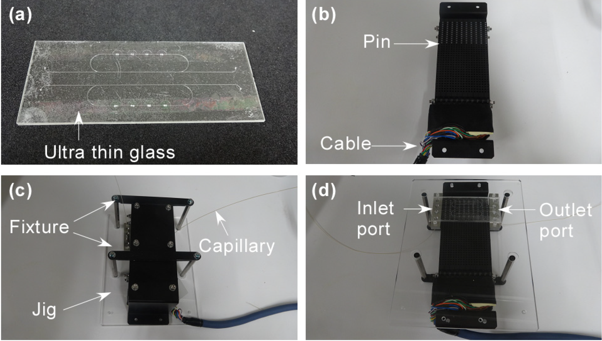
2.2. Fabrication of a Microchip

The fundamental microchip fabrication process with ultra thin glass using a hydrogen fluoride (HF) wet etching method was described in detail previously [31], and an overview is provided below.
The mechanically-polished glass substrates (top and bottom plates) were annealed before use. Next, Cr and Au layers were sputtered onto the substrates in vacuo, a positive photoresist was spin-coated onto the metal, and UV light was exposed through a photomask. The photoresist was then developed, and the metal layers were etched. Next, the bare glass surface with the microchannel pattern was etched with HF solution, and the remaining photoresist was removed. By this method, microchannels were fabricated in the bottom plate, and cavities were fabricated in the top plate. Penetration holes in the cavities (0.3 mm diameter) as well as inlet and outlet ports (0.4 mm diameter) were drilled into the top plate. The two plates and the ultra thin glass were chemically cleaned using piranha solution and mechanically polished. A Teflon jig was used for manipulation of fragile ultra thin glass for this cleaning step. Ultra thin glass sheets were then attached to the top plate to cover the cavities. Finally, the two plates were aligned and attached to each other manually, and thermally bonded in a furnace, followed by slow cooling program to maintain the flexibility of the ultra thin glass. By using this thermal fusion process, ultra thin glass sheets were tightly attached to the top plate and cover the chambers to prevent leakage.
A fabricated glass microchip is shown in Figure 2a. The width and depth of the main microchannel were about 300 μm and 100 μm, respectively. The depth of the cavities was about 50 μm, which is enough to close each valve.
Figure 2. Experimental set-up. (a) A picture of a microchip with an ultra thin glass sheet. (b) A picture of the actuator with the 110 individually-controlled. (c) A picture of a set-up microchip and actuator using a jig and 2 sets of fixtures. (d) A picture of the set up, from the bottom.
Micromachines 05 00289 g002

2.3. An Actuator and Software

The piezoelectric actuator was prepared to drive the pumps and flow fluids in the fabricated microchip as shown in Figure 2b. The actuators with 110 individually-controlled pins were customized by the KGS Corporation, Japan. The force generated by each pin was 0.2 N. The pitch of the pin was 4.8 mm (horizontal) and 2.4 mm (vertical). In this experiment, 4 continuous, horizontal pins were used for peristaltic pumping. Therefore, the pitch of the 4 valve chambers on the microchip was designed to be 4.8 mm.
The motion of the pins was controlled using customized software. The positions of the extruded pins were designated beforehand. The order of each design can be programmed in a list so that the design can be automatically changed. The minimum interval in the program is 0.02 s which is limited by the response time of the actuator. Therefore, the maximum frequency for this 4-valve peristaltic pump was 12.5 Hz.

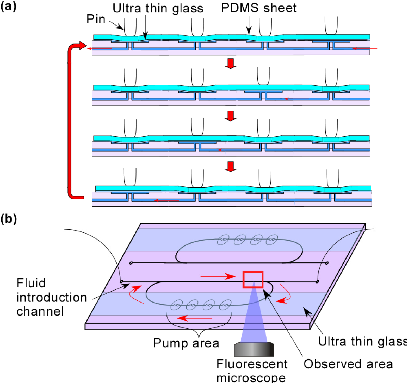
2.4. Experimental Setting

A jig made of acrylic resin was designed to fit the actuator and the microchip as shown in Figure 2c. After setting the microchip in the jig, the position of the actuator was aligned and fixed with two sets of fixtures using screws from the bottom side. Peak tube capillaries were then connected to the inlet and outlets ports via SUS connectors. The set up system is shown in Figure 2d. Fluid was controlled using a microfluidic flow controller (MFCS, Fluigent, Villejuif, France).
Micro tracking particles were used to visualize the fluid flow, as described in a previous report [40]. Fluorescent spherical polystyrene particles (Fluoro Spheres, 1 µm diameter, Molecular Probes, Invitrogen, Carlsbad, CA, USA) were dispersed into the fluid (diluted 100× with distilled water) and the fluid in the microchannel was observed in situ using a fluorescent microscope (IX-71, Olympus, Tokyo, Japan) with an objective lens (10×, 0.30-NA) and a GFP filter set as shown in Figure 1b. The microscope was focused on the center of the microchannel, and the image was recorded using interfaced software (cellSens, Olympus) through a CCD camera (DP72, Olympus). All experiments were carried out at room temperature.
In this experiment, fluid movement was measured not in the pump channel but in a side (bypass) channel to demonstrate circulation flow on a microchip, which must utilize an on-chip pump as previously reported [16].

3. Results and Discussion

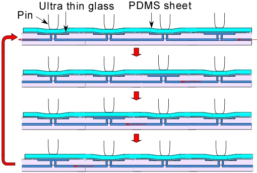
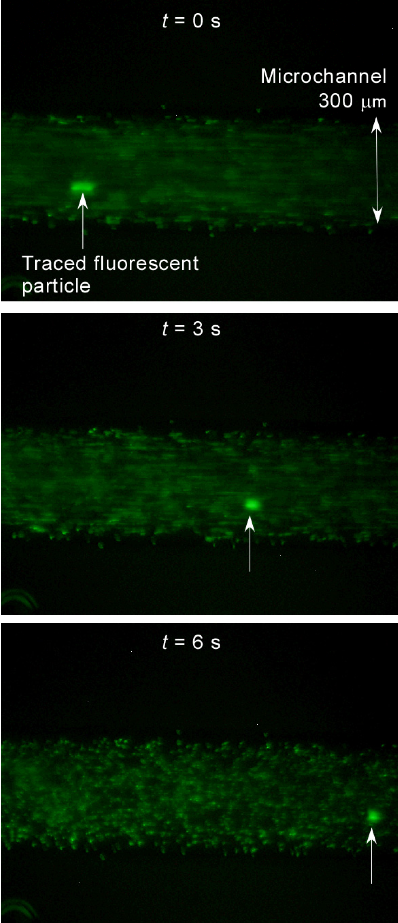
3.1. Demonstration of Pumping

Fluid visualized with micro polystyrene particles was introduced into the microchannel using MFCS. Fluid motion was monitored by following the movement of fluorescent polystyrene tracking particles to demonstrate pumping of fluid by the 4 serial valves. Before starting peristaltic pumping, flow from outside was stopped. Particle displacement to the right (x) was measured directly from sequential video frames of the microscopic video. Displacement at t = 0 s (at the time just starting pumping) was defined as x = 0 µm.
At first, the pumping frequency was set to 2.5 Hz. A video recording from just before pumping was started to the end of pumping is provided as Supplementary Video 1 in the Electronic Supporting Information. Some video stills from t = 0, 3 and 6 s are shown in Figure 3. Before pumping, the movement of the particles was minimal, which indicated that there was no net flow at inlet or outlet during operation. But after pumping was initiated, oscillation of the particles began, and a net movement of the particles to the right was apparent. The pump was actuated many times, but the glass sheet was not broken, indicating that the valve has good durability against mechanical fatigue.
From the measured displacement of several particles near the center of the microchannel in the video, the average flow velocity was calculated, and then, the flow rate was estimated by multiplying the width and depth of the microchannel (approximately 300 and 100 µm, respectively) as described in a previous report [15]. By this method, the flow rate was estimated to be 0.18 µL/min.
Figure 3. Pump demonstration using a circular microchannel by fluorescent microscopic pictures in a microchannel at t = 0 s (starting), 3 s, and 6 s. Green points indicate fluorescent particles.
Micromachines 05 00289 g003

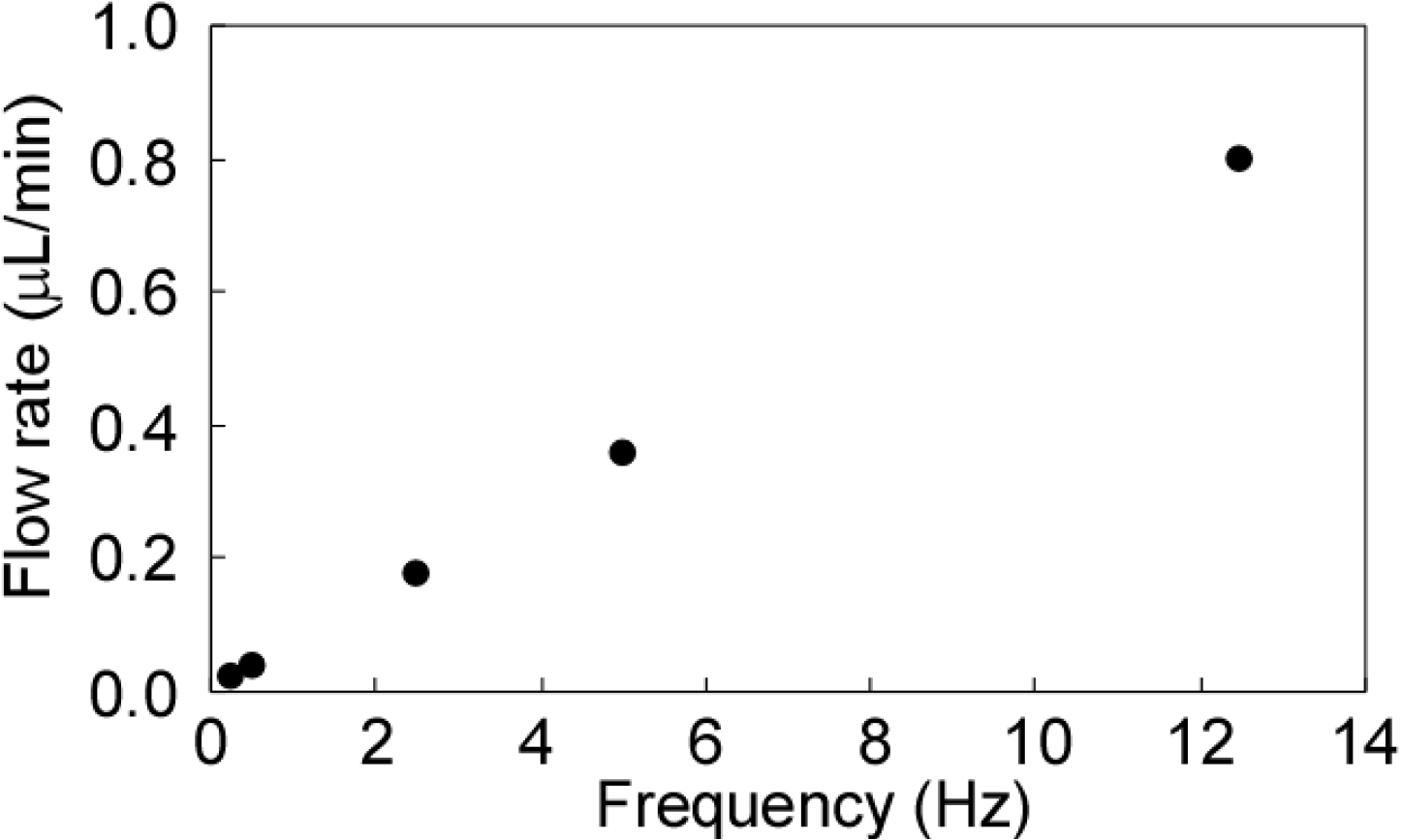
3.2. Dependency on Frequency

The frequency was changed from 0.25 to 12.5 Hz, which is the maximum value for this actuator, and the flow rate was estimated as described above. The result is shown in Figure 4. The flow rate was proportional to pumping frequency, and the maximum flow rate was about 0.80 µL/min. This result is roughly the same as that of a computer-controlled piezoelectric actuator-based PDMS on-chip pump reported previously [15].
This flow rate is compared with the flow rates used in integrated chemical systems for several practical applications on glass microchips [17,41,42] In these reports, the typical flow rates used for cell cultures in microchips are on the order of 0.1 µL/min; that used for analyses and syntheses in microchips is approximately 1 µL/min.
Thus, the pump demonstrated can be used for some of these applications. To increase flow rate, the interval of the actuator should be improved.
Pumping pressure was not measured this time. That will be a next step together with increment of flow rate by improvement of the system.
In this experiment, pumping duration was about 30 s corresponding to 375 times of actuating the pins at the highest frequency (12.5 Hz). The pump could stand at least in this continuous operation condition.
Figure 4. Pump flow rate vs. frequency as estimated by particle movement in a circular channel.
Micromachines 05 00289 g004

3.3. Performance Comparison with Other Micropumps on Chip

The performance of the developed pump was evaluated. A focused parameter here is self-pumping frequency (fsp) which is an integration index calculated by dividing the maximum flow rate at zero pressure delivery (Qmax) by package size (Sp) which indicates volume of fluid pumping chambers or channels. Since Sp of the developed pump is about 1.4 mm3 and 0.80 µL/min, fsp is calculated as 0.6 min−1. These values were compared with previously reported pumps in references raised above and also some new references as shown in Table 1.
Other types of pumps such as piezoelectric diaphragm [6,7,8], capillary pumps [35], electroosmotic pumps [36] and evaporation/condensation bubble pumps [37], have a very wide range of fsp value from 10−3 to 102 min−1 influenced by pumping principle rather than package size as also investigated in a past micropump review [4]. In these pumps, the developed pump is just placed in the moderate level not specially high or low.
By contrast, there is remarkable size dependency in comparison within peristaltic type pumps. Peristaltic pumps using glass as a diaphragm material as well as this study reported by Shoji et al. [43] and Smits et al. [44] require large diaphragm diameter (centimeter order) due to small deformability of normal thickness glass. This fact makes the system large and fsp small. Conversely, peristaltic pumps using elastomer as a diaphragm material [11,15,39] realize large fsp by integration. The nearest performance with the demonstrated pump within these peristaltic pumps is the one reported by Berg et al. [39]. They used 3-mm chambers as well as this report and near fsp value was obtained. In other words, the demonstrated pump here miniaturized chamber size by using ultra thin glass deformability and reached performance level (Sp and fsp) that has been realized only if using elastomer as a diaphragm material.
Table 1. Performance comparison of the demonstrated pump with other pumps regarding diaphragm materials, Sp (package size), Qmax (the maximum flow rate at zero pressure delivery), and fsp (self-pumping frequency). Sp and Qmax have two significant digits. fsp have one significant digit.
Pump typeReferenceDiaphragmSp (mm2)Qmax (µL/min)fsp (/min)
PeristalticThis studyGlass (Ultra thin)1.40.800.6
Piezoelectric diaphragm[6]Glass41008.00.0002
[7]Metal (Brass)2500160.0006
[8]Silicon981602
Capillary[35]-0.300.0260.09
Electroosmotic[36]-0.0110.00540.5
Bubble[37]-0.0394.5100
Peristaltic[43]Glass4000400.01
[44]Glass15001000.07
[39]Elastomer (PDMS)3.572
[15]Elastomer (PDMS)0.110.65
[11]Elastomer0.0011.4100

3.4. Confirmation of Durability against Organic Solvents

The pump newly developed here is the first entirely glass, completely compiled on-chip pump. Ultra thin glass is made not only with non-alkali glass, but also with soda lime- and borosilicate-based glass. Thus, there will be variety of applications in this field.
The most remarkable characteristic of this glass based device is that organic solvents can be used differently from PDMS based microchips. To verify this concept, ethanol was introduced in the microchip followed by pumping actuation at 12.5 Hz for 30 s as well as the experiment using water in the previous section. As a result, no visible glass destruction, ethanol leakage or air bubble contamination were observed during the actuation around the pumping chambers. Even after 30 min from pumping actuation, no evaporation was confirmed around the chambers. The same results were also obtained when using methanol and acetone. From this result, organic solvent durability was confirmed.

4. Conclusions

In this report, a peristaltic on-chip pump was generated by installing ultra thin glass onto a totally glass-based microchip. First, a microchip with 4 serial valve chambers was fabricated and piezoelectric actuators with customized jigs and operation software were prepared. Second, the pumping mechanism was demonstrated. An oscillating fluid flow visualized using fluorescently labeled polystyrene micro particles was observed. Finally, the relationship between pumping frequency and flow rate were investigated. The flow rate was proportional to the pumping frequency, and the maximum flow rate reached 0.80 µL/min.
Furthermore, this type of pump and valve assembly could contribute to the integration of general chemical analysis and synthesis systems using a glass microchip.

Acknowledgments

This study was supported by JSPS Grants-in-Aid for Young Scientist (A) (21681019), Young Scientist (A) (25709081), and Challenging Exploratory Research (23651133), Leading-edge Research Infrastructure Program, and from JST for Adaptable & Seamless Technology Transfer Program through Target-driven R&D (A-STEP) FS stage (AS251Z02348K), Japan. I thank KGS Co., Ltd., H. R. Ueda, H. Ukai, and Y. Shimizu in RIKEN, Japan for useful discussions.

Author Contributions

Y. Tanaka designed and carried out the project and wrote the paper.

Conflicts of Interest

The author declares that there is no conflict of interest.

References

  1. Kovarik, M.L.; Ornoff, D.M.; Melvin, A.T.; Dobes, N.C.; Wang, Y.; Dickinson, A.J.; Gach, P.C.; Shah, P.K.; Allbritton, N.L. Micro total analysis systems: fundamental advances and applications in the laboratory, clinic, and field. Anal. Chem. 2013, 85, 451–472. [Google Scholar] [CrossRef]
  2. Kitamori, T.; Tokeshi, M.; Hibara, A.; Sato, K. Thermal lens microscopy and microchip chemistry. Anal. Chem. 2004, 76, 52A–60A. [Google Scholar]
  3. Tanaka, Y.; Sato, K.; Shimizu, T.; Yamato, M.; Okano, T.; Kitamori, T. Biological cells on microchips: New technologies and applications. Biosens. Bioelectron. 2007, 23, 449–458. [Google Scholar] [CrossRef]
  4. Laser, D.J.; Santiago, J.G. A review of micropumps. J. Micromech. Microeng. 2004, 14, R35–R64. [Google Scholar] [CrossRef]
  5. Au, A.K.; Lai, H.; Utela, B.R.; Folch, A. Microvalves and micropumps for BioMEMS. Micromachines 2011, 2, 179–220. [Google Scholar] [CrossRef]
  6. Van Lintel, H.T.G.; van de Pol, F.C.M.; Bouwstra, S. A piezoelectric micropump based on micromachining of silicon. Sens. Actuators 1988, 15, 153–167. [Google Scholar] [CrossRef]
  7. Stemme, E.; Stemme, G. A valveless diffuser/nozzle-based fluid pump. Sens. Actuators A 1993, 39, 159–167. [Google Scholar] [CrossRef]
  8. Zengerle, R.; Ulrich, J.; Kluge, S.; Richter, M.; Richter, A. A bidirectional silicon micropump. Sens. Actuators A 1995, 50, 81–86. [Google Scholar] [CrossRef]
  9. Loverich, J.J.; Kanno, I.; Kotera, H. Concepts for a new class of all-polymer micropumps. Lab Chip 2006, 6, 1147–1154. [Google Scholar] [CrossRef]
  10. Xia, F.; Tadigadapa, S.; Zhang, Q.M. Electroactive polymer based microfluidic pump. Sens. Actuators A Phys. 2006, 125, 346–352. [Google Scholar] [CrossRef]
  11. Unger, M.A.; Chou, H.-P.; Thorsen, T.; Scerer, A.; Quake, S.R. Monolithic microfabricated valves and pumps by multilayer soft lithography. Science 2007, 288, 113–116. [Google Scholar]
  12. Quake, S.R.; Scherer, A. From micro- to nanofabrication with soft materials. Science 2000, 290, 1536–1540. [Google Scholar] [CrossRef]
  13. Thorsen, T.; Maerkl, S.J.; Quake, S.R. Microfluidic large-scale integration. Science 2002, 298, 580–584. [Google Scholar] [CrossRef]
  14. Melin, J.; Quake, S.R. Microfluidic large-scale integration: the evolution of design rules for biological automation. Annu. Rev. Biophys. Biomol. Struct. 2007, 36, 213–231. [Google Scholar] [CrossRef]
  15. Gu, W.; Zhu, X.; Futai, N.; Cho, B.S.; Takayama, S. Computerized microfluidic cell culture using elastomeric channels and Braille displays. Proc. Natl. Acad. Sci. USA 2004, 101, 15861–15866. [Google Scholar] [CrossRef]
  16. Song, J.W.; Gu, W.; Futai, N.; Warner, K.A.; Nor, J.E.; Takayama, S. Computer-controlled microcirculatory support system for endothelial cell culture and shearing. Anal. Chem. 2005, 77, 3993–3999. [Google Scholar]
  17. Hisamoto, H.; Shimizu, Y.; Uchiyama, K.; Tokeshi, M.; Kikutani, Y.; Hibara, A.; Kitamori, T. Chemicofunctional membrane for integrated chemical processes on a microchip. Anal. Chem. 2003, 75, 350–354. [Google Scholar] [CrossRef]
  18. Hiki, S.; Mawatari, K.; Aota, A.; Saito, M.; Kitamori, T. Sensitive gas analysis system on a microchip and application for on-site monitoring of nh3 in a clean room. Anal. Chem. 2011, 83, 5017–5022. [Google Scholar] [CrossRef]
  19. Jang, K.; Sato, K.; Tanaka, Y.; Xu, Y.; Sato, M.; Nakajima, T.; Mawatari, K.; Konno, T.; Ishihara, K.; Kitamori, T. An efficient surface modification using 2-methacryloyloxyethyl phosphorylcholine to control cell attachment via photochemical reaction in a microchannel. Lab Chip 2010, 10, 1937–1945. [Google Scholar] [CrossRef]
  20. Shang, F.; Guihen, E.; Glennon, J.D. Recent advances in miniaturisation—The role of microchip electrophoresis in clinical analysis. Electrophoresis 2012, 33, 105–116. [Google Scholar] [CrossRef]
  21. Yasui, T.; Kaji, N.; Mohamadi, M.R.; Okamoto, Y.; Tokeshi, M.; Horiike, Y.; Baba, Y. Electroosmotic flow in microchannels with nanostructures. ACS Nano 2011, 5, 7775–7780. [Google Scholar] [CrossRef]
  22. Kaji, N.; Okamoto, Y.; Tokeshi, M.; Baba, Y. Nanopillar, nanoball, and nanofibers for highly efficient analysis of biomolecules. Chem. Soc. Rev. 2010, 39, 948–956. [Google Scholar] [CrossRef]
  23. Sugioka, K.; Cheng, Y. Femtosecond laser processing for optofluidic fabrication. Lab Chip 2012, 12, 3576–3589. [Google Scholar] [CrossRef]
  24. Yıldırım, E.; Sahir Arıkan, M.A.; Külah, H. A normally closed electrostatic parylene microvalve for micro total analysis systems. Sens. Actuators A Phys. 2012, 181, 81–86. [Google Scholar] [CrossRef]
  25. Rolland, J.P.; van Dam, R.M.; Schorzman, D.A.; Quake, S.R.; DeSimone, J.M. Solvent-resistant photocurable “liquid Teflon” for microfluidic device fabrication. J. Am. Chem. Soc. 2004, 126, 2322–2323. [Google Scholar] [CrossRef]
  26. Dziuban, J.A.; Mroz, J.; Szczygielska, M.; Malachowski, M.; Gorecka-Drzazga, A.; Walczak, R.; Bula, W.; Zalewski, D.; Nieradko, L.; Lysko, J.; et al. Portable gas chromatograph with integrated components. Sens. Actuators A Phys. 2004, 115, 318–330. [Google Scholar] [CrossRef]
  27. Abate, A.R.; Lee, D.; Do, T.; Holtze, C.; Weitz, D.A. Glass coating for PDMS microfluidic channels by sol–gel methods. Lab Chip 2008, 8, 516–518. [Google Scholar]
  28. Kikutani, Y.; Mawatari, K.; Hibara, A.; Kitamori, T. Circulation microchannel for liquid–liquid microextraction. Microchim. Acta 2009, 164, 241–247. [Google Scholar] [CrossRef]
  29. Fenn, P.M.; Fisk, J.T.; Rhoads, R.L.; Rhoads, R.O. Defect Control in the Making of Sheet Glass by the Fusion Process. U.S. Patent 7,386,999, 17 June 2008. [Google Scholar]
  30. Fujiwara, K. Ultra thin glass. New Glass 2009, 24, 1033–1036. [Google Scholar]
  31. Tanaka, Y. Electric actuating valves incorporated into an all glass-based microchip exploiting the flexibility of ultra thin glass. RSC Adv. 2013, 3, 10213–10220. [Google Scholar] [CrossRef]
  32. Tanaka, Y.; Xi, H.; Sato, K; Mawatari, K.; Renberg, B.; Nilsson, M.; Kitamori, T. Single-molecule DNA patterning and detection by padlock probing and rolling circle amplification in microchannels for analysis of small sample volumes. Anal. Chem. 2011, 82, 3352–3357. [Google Scholar]
  33. Jang, K.; Xu, Y.; Sato, K.; Tanaka, Y.; Mawatari, K.; Kitamori, T. Micropatterning of biomolecules on a glass substrate in fused silica microchannels by using photolabile linker-based surface activation. Microchim. Acta 2012, 179, 49–55. [Google Scholar] [CrossRef]
  34. Jang, K.; Xu, Y.; Tanaka, Y.; Sato, K.; Mawatari, K.; Konno, T.; Ishihara, K.; Kitamori, T. Single-cell attachment and culture method using a photochemical reaction in a closed microfluidic system. Biomicrofluidics 2010, 4, 032208. [Google Scholar] [CrossRef]
  35. Zimmermann, M.; Schmid, H.; Hunziker, P.; Delamarche, E. Capillary pumps for autonomous capillary systems. Lab Chip 2007, 7, 119–125. [Google Scholar] [CrossRef]
  36. McKnight, T.E.; Culbertson, C.T.; Jacobson, S.C.; Ramsey, J.M. Electroosmotically induced hydraulic pumping with integrated electrodes on microfluidic devices. Anal. Chem. 2001, 73, 4045–4049. [Google Scholar]
  37. Tsai, J.H.; Lin, L. A thermal-bubble-actuated micronozzle-diffuser pump. J. Microelectromech. Syst. 2002, 11, 665–671. [Google Scholar] [CrossRef]
  38. Tanaka, Y. Totally Glass-Based Microchips with Valves and Pumps Using Flexibility of Ultra Thin Glass. In Proceedings of the 17th International Conference on Miniaturized Systems for Chemistry and Life Sciences (microTAS), Freiburg, Germany, 27–31 October 2013; pp. 1475–1477.
  39. Berg, J.M.; Anderson, R.; Anaya, M.; Lahlouh, B.; Holtz, M.; Dallas, T. A two-stage discrete peristaltic micropump. Sens. Actuators A 2003, 104, 6–10. [Google Scholar] [CrossRef]
  40. Tanaka, Y.; Yanagisawa, Y.; Kitamori, T. Fluid actuation for a bio-micropump powered by previously frozen cardiomyocytes directly seeded on a diagonally stretched thin membrane. Sens. Actuators B Chem. 2011, 156, 494–498. [Google Scholar] [CrossRef]
  41. Goto, M.; Sato, K.; Murakami, A.; Tokeshi, M.; Kitamori, T. Development of a microchip-based bioassay system using cultured cells. Anal. Chem. 2005, 77, 2125–2131. [Google Scholar] [CrossRef]
  42. Sato, K.; Tokeshi, M.; Odake, T.; Kimura, H.; Ooi, T.; Nakao, M.; Kitamori, T. Integration of an immunosorbent assay system: analysis of secretory human immunoglobulin A on polystyrene beads in a microchip. Anal. Chem. 2000, 72, 1144–1147. [Google Scholar] [CrossRef]
  43. Shoji, S.; Nakagawa, S.; Esashi, M. Micropump and sample-injector for integrated chemical analyzing systems. Sens. Actuators A 1990, 21, 189–192. [Google Scholar] [CrossRef]
  44. Smits, J.G. Piezoelectric micropump with 3 valves working peristaltically. Sens. Actuators A 1990, 21, 203–206. [Google Scholar] [CrossRef]

