Recent Trends on Micro/Nanofluidic Single Cell Electroporation


1
Institute of Nano Engineering and Microsystems, National Tsing Hua University, Kuang Fu Road, No. 101, Section 2, Hsinchu 30013, Taiwan
2
Department of Engineering and System Science, National Tsing Hua University, Kuang Fu Road, No. 101, Section 2, Hsinchu 30013, Taiwan
3
Division of Mechanics, Research Center for Applied Sciences, Academia Sinica, Nankang, 115 Taipei, Taiwan
*
Author to whom correspondence should be addressed.
Micromachines 2013, 4(3), 333-356; https://doi.org/10.3390/mi4030333
Submission received: 24 June 2013
/
Revised: 1 August 2013
/
Accepted: 20 August 2013
/
Published: 6 September 2013
(This article belongs to the Special Issue Micro/Nanofluidic Devices for Single Cell Analysis)
Abstract
:The behaviors of cell to cell or cell to environment with their organelles and their intracellular physical or biochemical effects are still not fully understood. Analyzing millions of cells together cannot provide detailed information, such as cell proliferation, differentiation or different responses to external stimuli and intracellular reaction. Thus, single cell level research is becoming a pioneering research area that unveils the interaction details in high temporal and spatial resolution among cells. To analyze the cellular function, single cell electroporation can be conducted by employing a miniaturized device, whose dimension should be similar to that of a single cell. Micro/nanofluidic devices can fulfill this requirement for single cell electroporation. This device is not only useful for cell lysis, cell to cell fusion or separation, insertion of drug, DNA and antibodies inside single cell, but also it can control biochemical, electrical and mechanical parameters using electroporation technique. This device provides better performance such as high transfection efficiency, high cell viability, lower Joule heating effect, less sample contamination, lower toxicity during electroporation experiment when compared to bulk electroporation process. In addition, single organelles within a cell can be analyzed selectively by reducing the electrode size and gap at nanoscale level. This advanced technique can deliver (in/out) biomolecules precisely through a small membrane area (micro to nanoscale area) of the single cell, known as localized single cell membrane electroporation (LSCMEP). These articles emphasize the recent progress in micro/nanofluidic single cell electroporation, which is potentially beneficial for high-efficient therapeutic and delivery applications or understanding cell to cell interaction.
1. Introduction
Electroporation or electropermeabilization is a powerful technique for biological cell studies. To apply high external electric field, cell membranes can increase their electrical conductivity and permeability due to structural change of the membrane to create transient hydrophilic pores from initially formatted hydrophobic pores. This process is usually known as electroporation or electropermeabilization [1,2,3,4,5]. The transient hydrophilic pores enable the delivery of biomolecules such as drugs, antibodies, DNA, RNA, dyes, ions, oligonucleotides from outside to inside of the cell [6,7,8,9] or intracellular cytosolic compounds from inside to outside of the cell [10,11]. The formation of hydrophilic stable or unstable pores mainly depends upon electrical field strength, the number of pulses, time between two pulses, etc. After application of external electric field surrounding cell medium, ions can move and accumulate as charges on cell membrane surface. This accumulation of charges can create an electric field inside cell membrane. As a result, electrical field strength generated inside the cell membrane is completely different from outside of the cell membrane [12]. This potential difference is called as transmembrane potential (TMP), which linearly proportional to the external electric field and the diameter of the cell. For a spherical cell, the TMP can be expressed by Schwan’s equation as:
![Micromachines 04 00333 i001]() where φi − φe is the potential difference between intracellular and extracellular membrane, r is the radius of the cell, E0 is the applied electric field strength and θ is the angle between direction of electric field and the selected point of the cell surface [13,14]. To apply high external electric field with longer pulses (ms), TMP can increase and hydrophobic pores became hydrophilic one at threshold TMP values (0.2–1 V) [6,15,16,17,18,19]. After withdraw the pulse, the membrane can reseal again without mechanical rupture and the phenomenon is known as reversible electroporation [19,20]. However, to apply very high external electric field, the cell membrane can deform permanently, whereas the membrane cannot reseal again resulting cell lysis, and the process known as irreversible electroporation [21,22].
where φi − φe is the potential difference between intracellular and extracellular membrane, r is the radius of the cell, E0 is the applied electric field strength and θ is the angle between direction of electric field and the selected point of the cell surface [13,14]. To apply high external electric field with longer pulses (ms), TMP can increase and hydrophobic pores became hydrophilic one at threshold TMP values (0.2–1 V) [6,15,16,17,18,19]. After withdraw the pulse, the membrane can reseal again without mechanical rupture and the phenomenon is known as reversible electroporation [19,20]. However, to apply very high external electric field, the cell membrane can deform permanently, whereas the membrane cannot reseal again resulting cell lysis, and the process known as irreversible electroporation [21,22].

Micro/nanofluidic devices are potentially beneficial for single cell electroporation. The main advantage of these devices are easy operation, low cost, portability, lower power consumption, very short reaction time, less toxic issue, small volume of reagent consumption when compared to bulk electroporation process (BEP) [23,24,25,26]. These devices can isolate single cell from population of millions of cells together and an inhomogeneous electric field can be focused only on single cell where remaining cells are unaffected. As a result, single cell manipulation can be performed from population of cells together. These devices can analyze cell to cell behavior with their organelle, their orientation, changes of cell size and shape with different polarities of electric fields [14,23,24,26,27]. On the other hand, bulk electroporation needs two large electrodes surrounding millions of cells together and a homogeneous electric field is applied to electroporates millions of cells at once. As a result, cell to cell behavior is difficult to analyze clearly. Due to a large gap between two electrodes, an additional voltage is required (several hundred volts) for the electroporation process. Higher voltage can provide higher electrical field strength, by which some of the cells can rupture and some of them are unaffected from millions of cells, resulting in lower transfection rate and cell viability when compared with single cell electroporation [24]. Larger size electrode can provide a larger surface area to react with a large volume of cell medium; however, toxic issues during the electroporation process will arise and might reduce the cell viability. This toxic issue mainly depends upon electrode materials [28]. For micro/nanofluidic devices, where the dimension of the devices are in micro to nanoscale label, which is similar to single cell dimension (microchannel). As a result, single cell can trap/sort easily for electroporation experiment. Moreover for specific design of microchannel, the device can supply nutrients to the cells and experiment can be performed many times without resuspended the cells and removal of cells without cell adhesive reagent, which is not possible in bulk electroporation process.
Recently, single cell electroporation (SCEP) research approaches in more advance stages, where the dimension of the micro/nanofluidic devices reaches from micro to nanoscale level. To use this dimensional advantage, an electric field can easily intense in the local region of the single cell membrane, by which high transfection rate and high cell viability were achieved [27,29]. However localized electroporation can also be performed by nanochannel ion transportation using the electrophoresis method [30]. To apply electrical field in local region of the single cell membrane, the process is known as localized single cell membrane electroporation (LSCMEP), by which precise and controllable drug delivery is possible [27,29,30]. The LSCMEP process can provide very high transfection rate, high cell viability, low power consumption, lower toxicity, low thermal effect in comparison with SCEP or BEP process.
2. Bulk, Single and Localized Single Cell Membrane Electroporation
2.1. Bulk Electroporation (BEP)
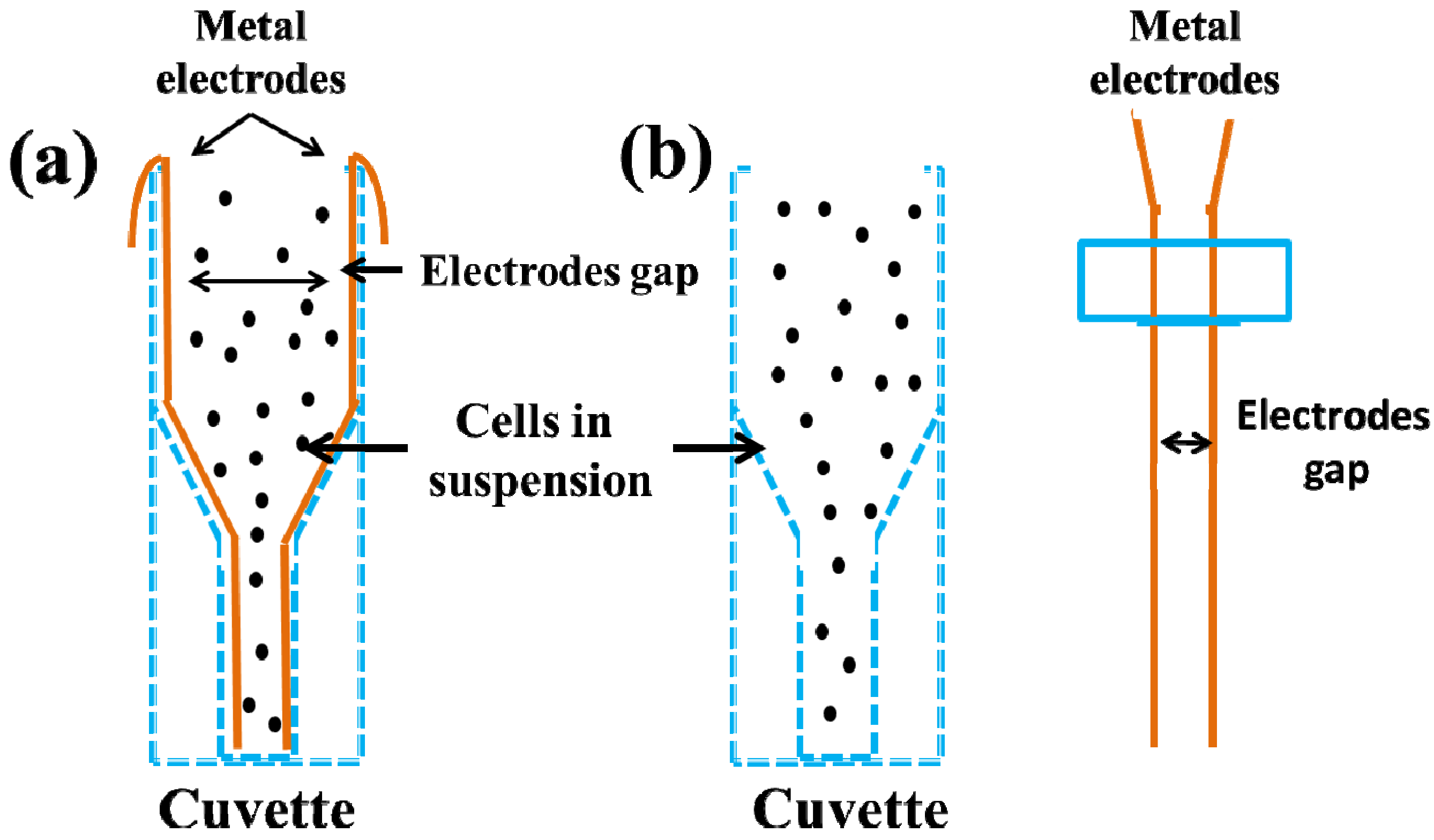
In Bulk electroporation (BEP) process, a homogeneous electric field is applied with suspension of millions of cells together, where two large electrodes are separated with larger distance. To transfect cells with BEP process, a very high external electric field (KV cm−1) is needed to induce transmembrane potential, which must be exceed the cell membrane threshold values [31]. As result, transient electropermeabilized pores can form on the cell membrane to deliver exogenous biomolecules from the outside to the inside of the cell. Figure 1a shows the cuvette with suspensions of millions of cells in between two metal electrodes (the distance between two metal electrodes varied inside the cuvette, as result induced electric field is different from top to bottom of the cuvette). Whereas in Figure 1b, cells are suspension into the cuvette and metal electrodes can introduce from outside to inside of the cuvette. The gap between two metal electrodes are almost same in each position of the cuvette and electric field can act uniformly onto the cell membrane inside the cuvette. Both of this cuvette, cells are suspension in between two metal electrodes, as result a homogeneous electric field can act on to the cell membrane to deliver substances inside the cells with high electric field.
Figure 1.
The bulk electroporation apparatus in vitro experiment with cross sectional view of two metal electrodes. The distance between two large electrodes varies from millimeter to centimeter range. To manufacture of this device is simple but the voltage requirement is very high to permeabilize of millions of cells together due to large distance between two electrodes (a) cells are in suspension within the cuvette, where two metal electrodes are fixed inside the cuvette for electroporation experiment (b) cells are suspension and metal electrodes can introduce from outside to inside of this cuvette. Figure has been redrawn from reference [31].

2.2. Single Cell Electroporation (SCEP)
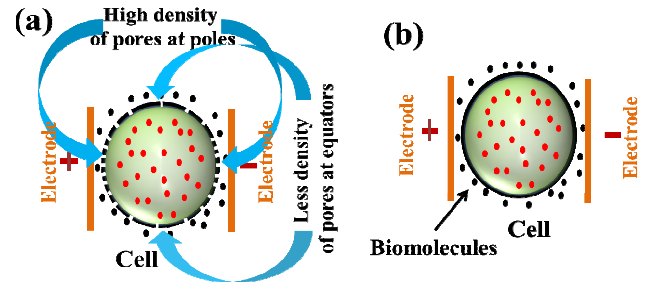
In single cell electroporation (SCEP), an inhomogeneous electric field is applied surrounded the single cell, where distance between two electrodes is in micro scale level (single cell dimension). Micro/nanofluidic devices dimension almost reaches to this level to position each single cell with micro-channel flow control and it can perform successful single cell transfection or single cell lysis. Figure 2 shows how an electric field influences single cells to form membrane nano-pores during the electroporation process. From this figure, the maximum electric field is at the poles of the cell (light color across the cell membrane position) and minimum is at the equators (deep color on top and bottom of the cell membrane). As a result, the transmembrane potential is different in each point of the cell membrane. High transmembrane potential induces at the poles of the cell and low transmembrane potential at the equators (according to Equation (1)), resulting formation of higher density of pores at the poles and lower density of pores at the equators. To reduce the gap between two electrodes by using micro/nanofluidic devices, the requirement of voltage should be lower compared to the bulk electroporation process. In this device, single cell manipulation with their cytosolic compound can be analyzed easily. Figure 3 shows single cell electroporation, where external electric field is applied outside of the single cell. Figure 3a shows the formation of different density of pores at different position of the single cell membrane due to variation of electric field strength. Maximum pores form at the poles due to higher electric field (see Equation (1)) and minimum density of pores form at the equators due to less electric filed affect. Figure 3b shows that, after withdrawing the electric field, cell membranes reseal again, as a result biomolecules enter successfully inside the single cell.
Figure 2.
Electric field distribution for single cell electroporation where induced transmembrane potential is maximum at the cell pole and minimum at the equator.
Figure 2.
Electric field distribution for single cell electroporation where induced transmembrane potential is maximum at the cell pole and minimum at the equator.
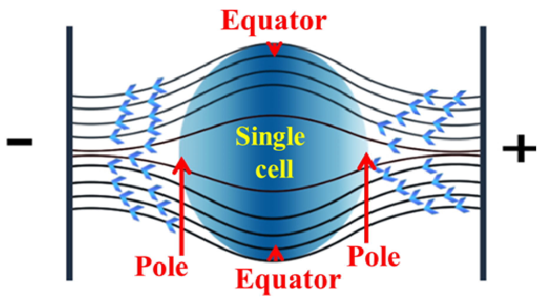
Figure 3.
Single cell electroporation (SCEP), where an external electric field applied outside of the single cell (a) formation of pores due to electric field application (maximum pores open at poles and minimum pores open at the equators due to different field strength at different positions of the membrane); (b) after withdrawing the pulse, cell membranes reseal again and biomolecules enter successfully inside the single cell.
2.3. Localized Single Cell Membrane Electroporation (LSCMEP)
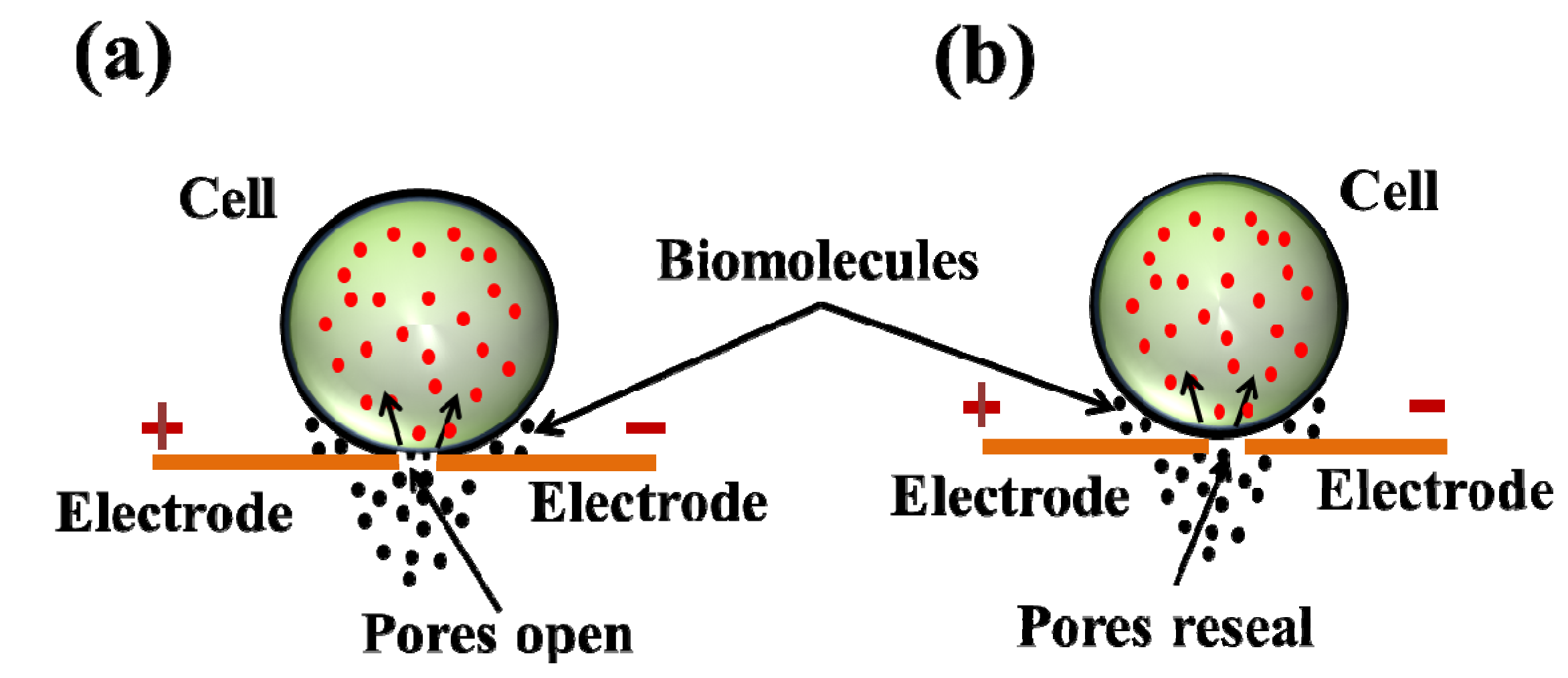
In the last couple of years, device fabrication approaches towards the nanoscale level, where the gap between two electrodes is reduced to nanometer scale. As the gap between the electrodes reduces significantly, the electric field can intensify only a nanometer region in-between two electrodes. To use micro/nanofluidic devices, single cells can be positioned on top of the nanoelectrode and cell membranes can deform only on nano-scale region (reaming cell membrane area will be unaffected) to deliver drugs from outside to inside of the cell. The process as known as localized single cell membrane electroporation (LSCMEP) [29]. Figure 4 shows the LSCMEP process, where Figure 4a shows how the cell membrane deforms and opens up the pores due to application of electric field. As a result, biomolecules enter from outside to inside of the single cell. Figure 4b shows the cell membrane resealing after withdrawing the pulses, where biomolecules enter successfully inside the single cell.
This new approach leads to lower voltage requirements, high transfection efficiency, high cell viability, low toxicity, low sample volume, very low Joule heating effect in compare with SCEP or BEP process. Until now, the fabrication of such devices is in the development stage. In the near future researchers need to pay more attention to developing micro/nanofluidic LSCMEP devices for better understanding of single cell analysis with their intracellular biochemical effect.
Figure 4.
Localized single cell membrane electroporation (LSCMEP) where electric field is applied in a specific region (nano-scale region) of the cell membrane. (a) During electroporation, membrane pores open and biomolecules deliver from outside to inside of the single cell; (b) After electroporation cell membranes reseal again and biomolecules entered successfully inside the single cell. Permission to reprint obtained from Springer [27].

3. Micro/Nanofluidic Devices for Single Cell Electroporation
For single cell electroporation, micro/nanofluidic devices are essential to analyze intracellular reaction in response to external stimuli. The transfection rate depends upon electric field strength, number of pulses and duration of pulses. Generally, smaller size biomolecules can enter inside a single cell by the diffusion process whereas the larger size such as DNA can enter inside the single cell by the electrophoretically driven process. It was reported that short and strong electric field pulses can provide reversible electroporation [32,33]. However, ultrashort nanosecond pulses with higher electric field can provide irreversible electroporation [10]. The permeabilization area can be controlled with the pulse amplitude and the degree of permeabilization can be controlled with the duration of pulses, numbers of pulses, where longer pulses provide a larger perturbation area in the cell membrane [34,35]. In earlier studies of micro/nanofluidic based single cell electroporation, authors analyze cellular content and cellular properties [36,37,38,39], transfection of cells [17,40,41,42] and inactivating cells [43,44,45] with the use of micro-channel based electroporation [46,47,48,49], micro-capillary based electroporation [50,51,52], electroporation with solid microelectrode [36,53,54,55], membrane sandwich based microfluidic electroporation [56,57], microarray single cell electroporation [58], optofluidic based microfluidic devices [59,60,61,62,63,64,65], etc. Table 1 describes in detail micro/nanofluidic based single cell transfection, cell lysis, cell type with species, potential difference, pulse duration, etc.
In this article, we emphasize the details about single cell transfection and lysis by using micro/nanofluidic devices with cell trapping and droplet microfluidics technique, single cell transfection and lysis with localized single cell membrane electroporation (LSCMEP) technique. Also, we compared the advantage and future prospect of LSCMEP process with SCEP and BEP process. Finally, we have drawn some conclusions between BEP, SCEP and LSCMEP process.

| Year and References | Potential difference | Pulse time | Cell type | Spices | Purpose |
|---|---|---|---|---|---|
| 1999 [66] | 0–60 V | 2 µs–100 ms | ND-1
ATCC#CRL-1439 | Human Rat | Transfection and lysis |
| 2001 [41] | 10 V | 5 ms | Huh-7 | Human | Transfection |
| 2003 [67] | 1125 V | Continuous DC | Jurkat | Human | Lysis |
| 2003 [38] | 20 V | ±20 s AC | S. cerevisiae | Yeast | Lysis |
| 2004 [68] | 1400 | 1 s | Erythrocytes | Human | Lysis |
| 2005 [69] | 0.1–1 V | 10 KHz AC | HeLa | Human | Transfection |
| 2006 [70] | 400 V/cm, 600–1200 V/cm | 10 µs–20 ms, 30 ms | CHO | Hamster | Transfection and lysis |
| 2006 [71] | 2000 V/cm | Continuous DC | E. coli | Bacterial | Lysis |
| 2007 [72] | 10 VPP | 1 MHz | Zucchini protoplast cells | Plant | Lysis |
| 2008 [73] | 1–3 V | 6 ms | C2C12 | Mouse | Transfection |
| 2008 [29] | 1 VPP | 0.5 Hz | Fibroblast cell | Rat | Transfection |
| 2008 [46] | <20 V | 100 KHz–1 MHz | A431 squamous cell | Human | Lysis |
| 2009 [74] | 5 Vrms | 40 Hz | FITC-BSA-laden vesicle | - | Lysis |
| 2010 [75] | <3 V | Continuous DC | - | Yeast | Transfection |
| 2012 [27] | 10 µs, 20 ms | 8 VPP | HeLa | Human | Tranfection |
| 2012 [30] | 1–60 ms | 60–260 V/2 mm | K 562, Jurkat | Human | Transfection |
| 2012 [76] | 1.3 V | Continuous DC | Algal cell | Plant | Transfection |
| 2013 [77] | 600–90 m Vpp | 2 ms | HT-29 | Human | Lysis |
3.1. Single Cell Transfection
3.1.1. Trapping Based Single Cell Transfection
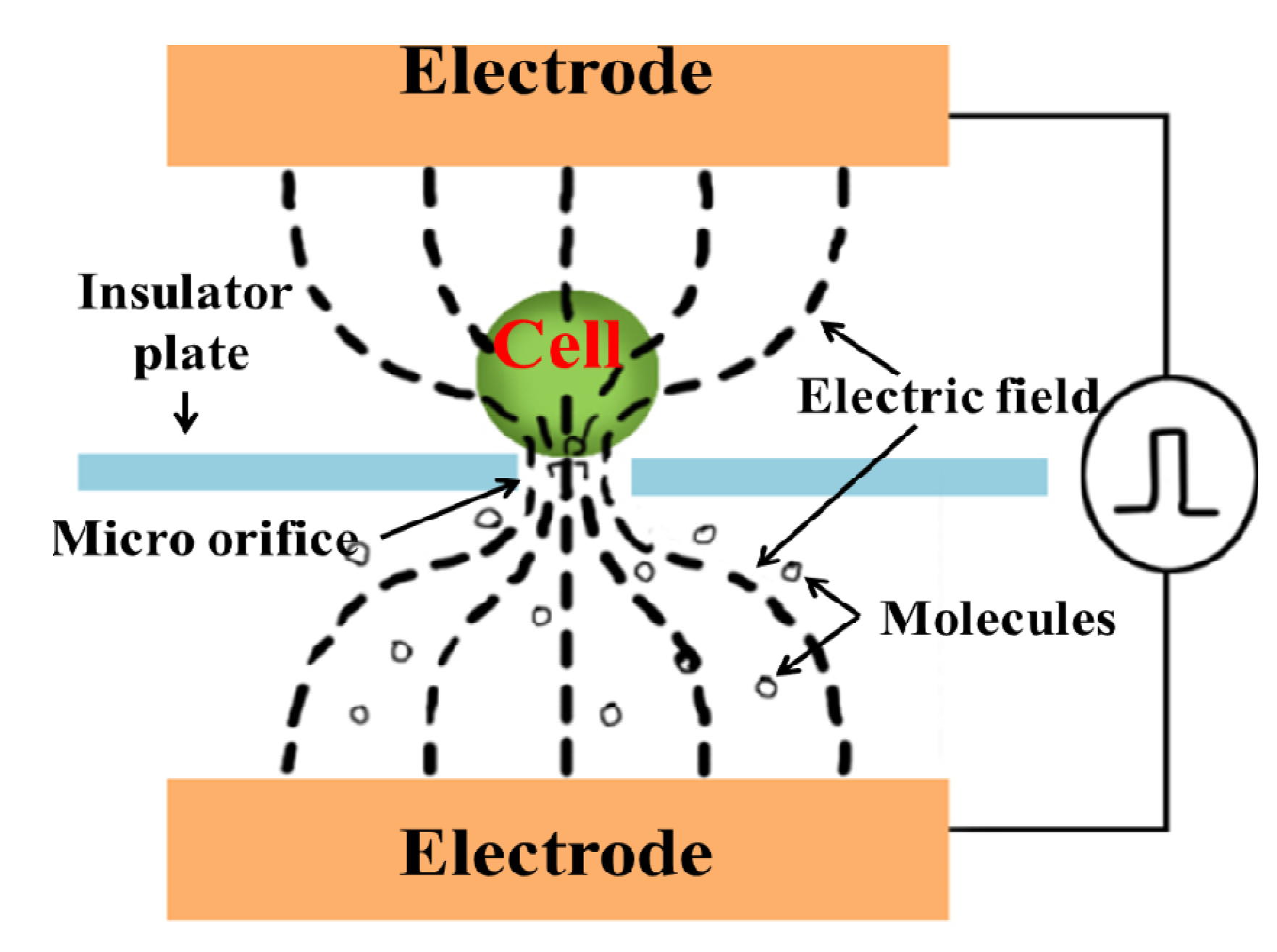
The first microfluidic device with cell trapping was proposed by Huang et al. in 1999 [66]. This device was fabricated with two chambers (top and bottom), which were separated by silicon nitride layer (1 µm). Figure 5 shows the schematic of the device for single cell electroporation. The top and bottom layer were fabricated with n+ polysilicon layer, which was a conducting and transparent layer. As a result, the device was transparent and light from the microscope could pass throughout the device. One hole (2 µm to 10 µm) was formed in middle layer by reactive ion etching technique. Two chambers were filled with saline had different pressures: the top chamber was higher pressure than the bottom chamber, meaning cells had the tendency to flow from the top to bottom chamber. As the lowered pressure in the bottom chamber, the cell was trapped in a hole, which was formed in the middle layer. Then continuous DC power supply was supplied between two chambers with amplitude 0–120 V and 2 µs to 100 ms pulse duration. The distances between two electrodes were 900 µm. After application of electric field, it was constricted through the hole, which increased the transmembrane potential of the cell membrane, and finally the membrane was electrically permeabilized to enter exogenous molecules from outside to inside of the single cell. Later, the same author has proposed different types of microfluidic devices for single cell transfection in 2001 and 2003 [78,79]. Figure 6 shows flow through based microfluidic chip for single cell transfection. In Figure 6a, cells flowed one by one through the micro-channel. The width of the micro-channel was higher than the cell dimension. When the cell was near the vicinity of the hole, due to back pressure (lower pressure) on the bottom channel, the single cell was trapped easily on the hole. As the application of electric field with proper pulse (10 V with 10 ms), the cell membrane was permeabilized, to enter foreign biomolecule inside the single cell. After electroporation, back pressure was withdrawn. As a result, a single cell was released from the hole and the next cell was ready to trap for another electroporation. With this microfluidic design, different cells can electroporate with different duration of pulses and different types of exogenous biomolecules can enter inside the single cell according to electroporation experiment requirement. Figure 6b shows the optical microscope image of micro-channel with hole and electrodes. The success rate for single cell trapping and electroporation effectiveness can be achieve 100% for this micro-electroporation method. This device transfected EGFP into SK-OV-3 cells with the application of 0.4 KV/cm electric field.

Another cell trapping with microfluidic device for single cell electroporation was proposed by Khine et al. in 2004 [80]. The device was fabricated with polydimethylsiloxane (PDMS), where silicon substrate was used as a mold for PDMS. In this device, two wider channels were used for cell inlet and outlet. The middle circular section, where cells can be released from the main channel and it was connected with many micro-channels for single cell trapping. The diameter of each micro-channel was 3.1 µm, which was one third of the cell diameter. As a result, localized electroporation was performed with this micro-channel based device. Later, the detailed manufacturing process of such trapping device was proposed by Suzuki et al. [81]. In this device, Ag/Agcl electrode was connected with each micro-channel and main inlet channel. After cell loading through the main inlet channel to the circular area, negative pressure was applied to the micro-channel. Then, the single cell was trapped with the micro-channel. The electroporation was measured to use the circuit model of this device. Cell membrane permeabilization was measured by characteristic “jumps” in the current that correspond to drops in cell resistance. The reversible electroporation was performed with this device by applying 0.76 ± 0.095 V with 6.5 ms pulse. This device can deliver drugs, DNA and protein inside the single cell. The feasibility of introducing foreign material with permeabilized single cell was tested with trypan blue for suspension of cells.
Figure 6.
(a) Concept of flow through micro-electroporation chip; (b) Optical image of micro-channel, micro-hole and electrodes. Permission to reprint obtained from Elsevier [78].
Figure 6.
(a) Concept of flow through micro-electroporation chip; (b) Optical image of micro-channel, micro-hole and electrodes. Permission to reprint obtained from Elsevier [78].
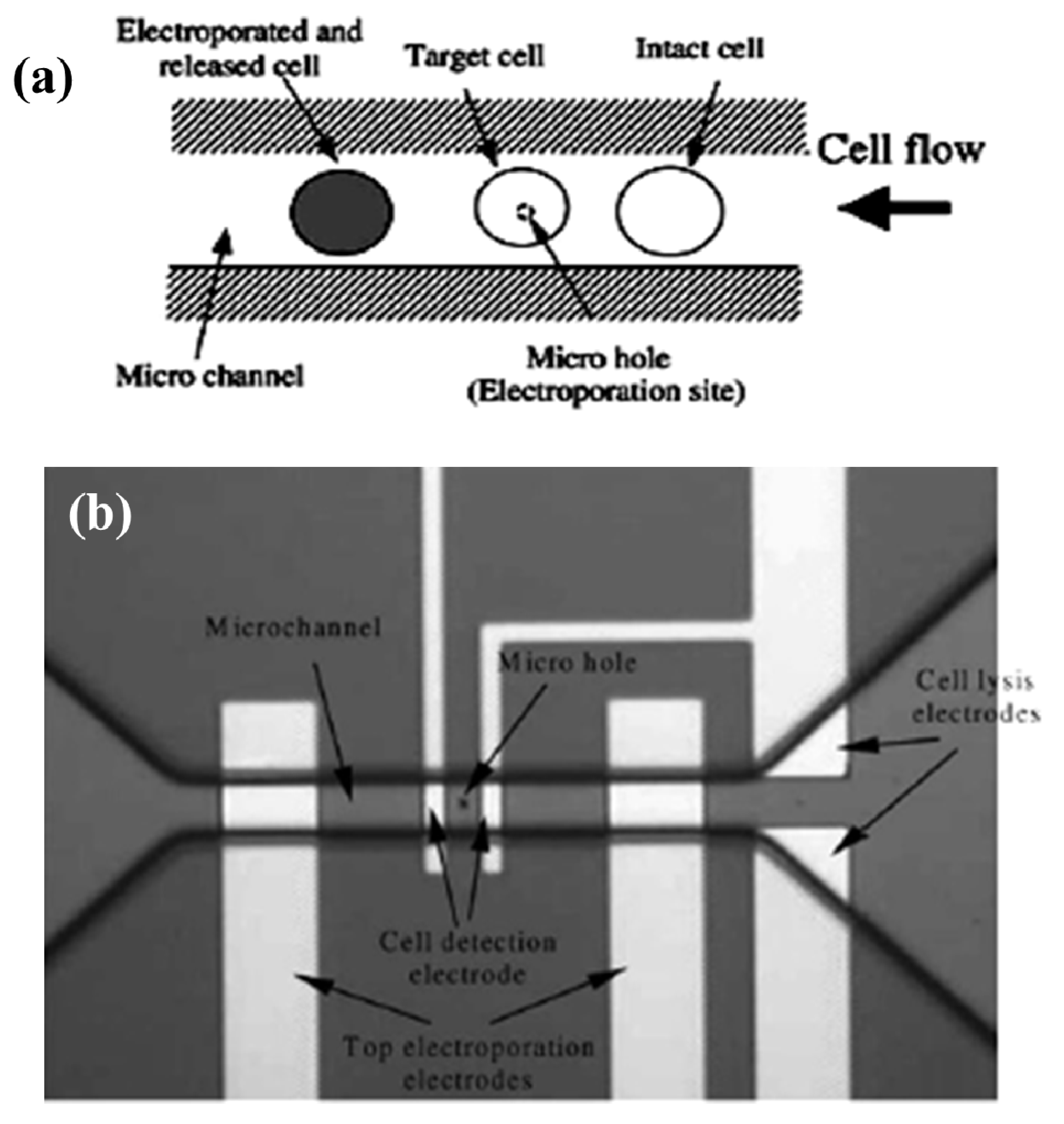
Figure 7.
The schematic steps for electrophoresis driven cell loading protocol (a) preconcentrate; (b) membrane electroporation; (c) apply electrophoretic driving force. Figure has been redrawn with reference [82].
Figure 7.
The schematic steps for electrophoresis driven cell loading protocol (a) preconcentrate; (b) membrane electroporation; (c) apply electrophoretic driving force. Figure has been redrawn with reference [82].
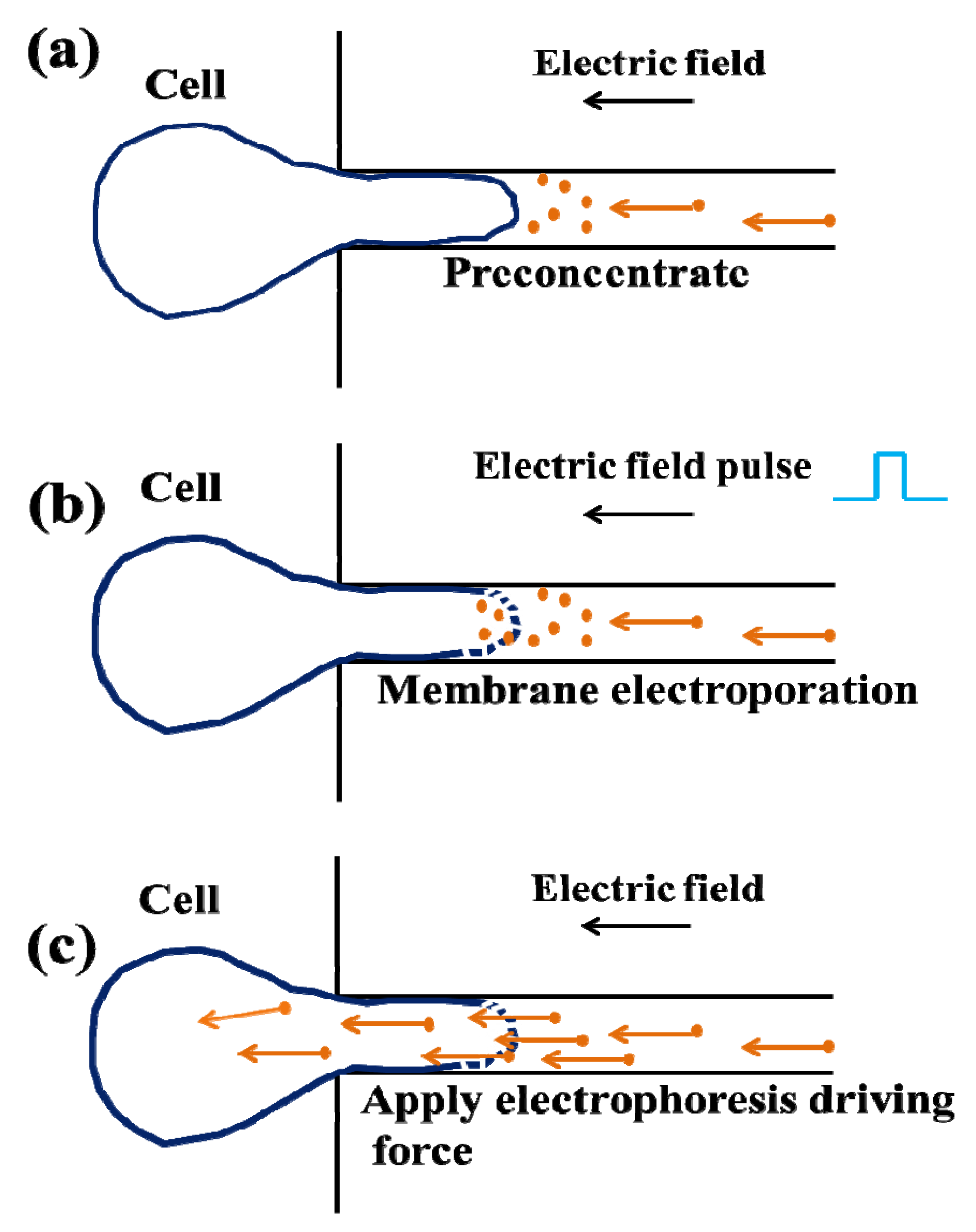
In 2008, Ionescu-Zantti et al. [82] proposed electrophoresis driven microfluidic based electroporation device for single cell trapping and transfection. Figure 7 shows the schematic steps for an electrophoresis based electroporation device. This device was fabricated with PDMS, where 3 µm × 3 µm capillaries microchannel was formed for single cell trapping and focusing the electric field. Initially, a cell was trapped through the capillary channel by using negative pressure and then 0–300 mV external field was applied (this field was below the cell membrane threshold values (0.5–2 V)) for electrophoretically preconcentrate the dyes near the cell membrane (see Figure 7a). After that, larger pulses were applied (5–30 ms) for the electroporation process (see Figure 7b) and dye was loaded during resealing of the cell membrane by applied lower electric field (Figure 7c). This method reduced the dye loading time into the single cell by its unique design.
Another group, Valero et al. [73] in 2008, proposed microfluidic device which delivered PI dye to use single mouse myoblast C2C12 cells with high transfection efficiency (>75%). In 2012, Gac et al. [83] suggested a new microfluidic device by which they trapped individual cell in micrometer-size structure within a microchip and exposed an intense electric field with plasmid/dye. This device includes an array of independent electroporation sites, which electroporates nine cells together.
3.1.2. Droplet Microfluidics for Single Cell Transfection
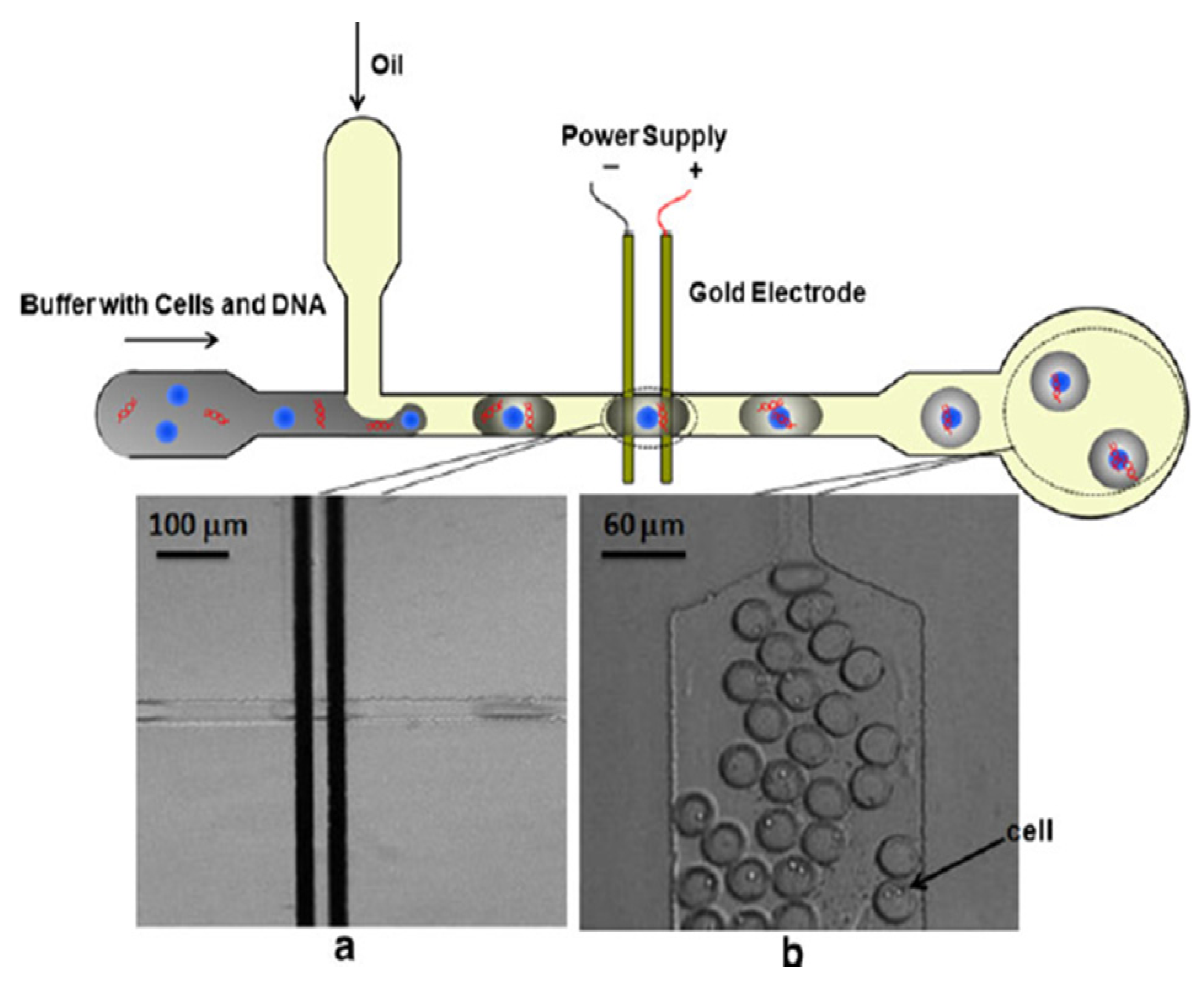
Droplet microfluidic based single cell electroporation has raised a lot of interest in recent years for biological and therapeutic studies. This technique leads to high throughput screening application for single cell analysis. Droplets can encapsulate cells, DNA, dye, particles or molecules that are in the inner aqueous phase [84]. Recently, droplet microfluidic have wide applications in biotechnology such as animal cell growth in encapsulated droplet in picoliter range, with high cell viability [85]. The first droplet microfluidic based electroporation was proposed by Luo et al. [86] in 2006. They used the electrochemical detection method for aqueous droplet analysis in oil phase of microfluidic device. Electrochemical signal difference was held between oil and aqueous. This method provides the size information and ion concentration, which leads from 0.02 mmol/L to 1 mol/L of tens of picoliter to nanoliter aqueous droplet. In 2009 Zhan et al. proposed droplet microfluidic based single cell electroporation [87]. The device was fabricated with polydimethylsiloxane (PDMS) by using standard soft lithographic process. A 150 nm thickness based microelectrode was fabricated with e-beam evaporation and lithographic process. Figure 8 shows the droplet microfluidic based single cell electroporation process. This device has two inlets, one outlet and one pair of electrodes. Electroporation can be performed with droplet containing single cell. The buffer with cells and DNA was loaded in one inlet channel, where the cell was introduced by syringe pump with magnetic stair. In magnetic stair, the magnetic field can rotate to cause stair bar, which is immersed in medium with cells, making cells spin to avoid cells settling down. Another inlet channel was used for oil pumping. Droplets with cell of different sizes were produced by adjusting the flow rates between oil and buffer solution. The size of each droplet with a cell was 60–386 µm in length and this droplet containing a cell was electroporated with droplet velocity 1.38–8.86 m/min to apply 5–9 V constant DC voltage in-between 20 µm electrodes gap. Due to application of DC voltage, an electric field can act on a droplet containing conducting buffer solution and it electroporates a single cell within the droplet. This device achieved 68% cell viability with 4.7 volt applied voltage after electroporation; however, viability reduced down to 14% for 7.1 volt applied voltage. Also it transfected plasmid vector coding EGFP into Chinese Hamster Ovary (CHO) cell. The cell transfection rate was 11% due to 5.8 V, 1.8 ms pulse application. Thus droplet size, droplet velocity, electric field strength and distance between two electrodes are important to achieve high transfection and high cell viability. Droplet microfluidics is potentially applicable for high throughput functional screening of genes, which is not possible in the bulk electroporation process.
Figure 8.
Layout and performance of a droplet based microfluidic device (a) two microelectrodes, where cells can be positioned for electroporation; (b) after electroporation, a droplet with a cell at the end of the device. Permission to reprint obtained from American Chemical Society (ACS) [87].
Figure 8.
Layout and performance of a droplet based microfluidic device (a) two microelectrodes, where cells can be positioned for electroporation; (b) after electroporation, a droplet with a cell at the end of the device. Permission to reprint obtained from American Chemical Society (ACS) [87].
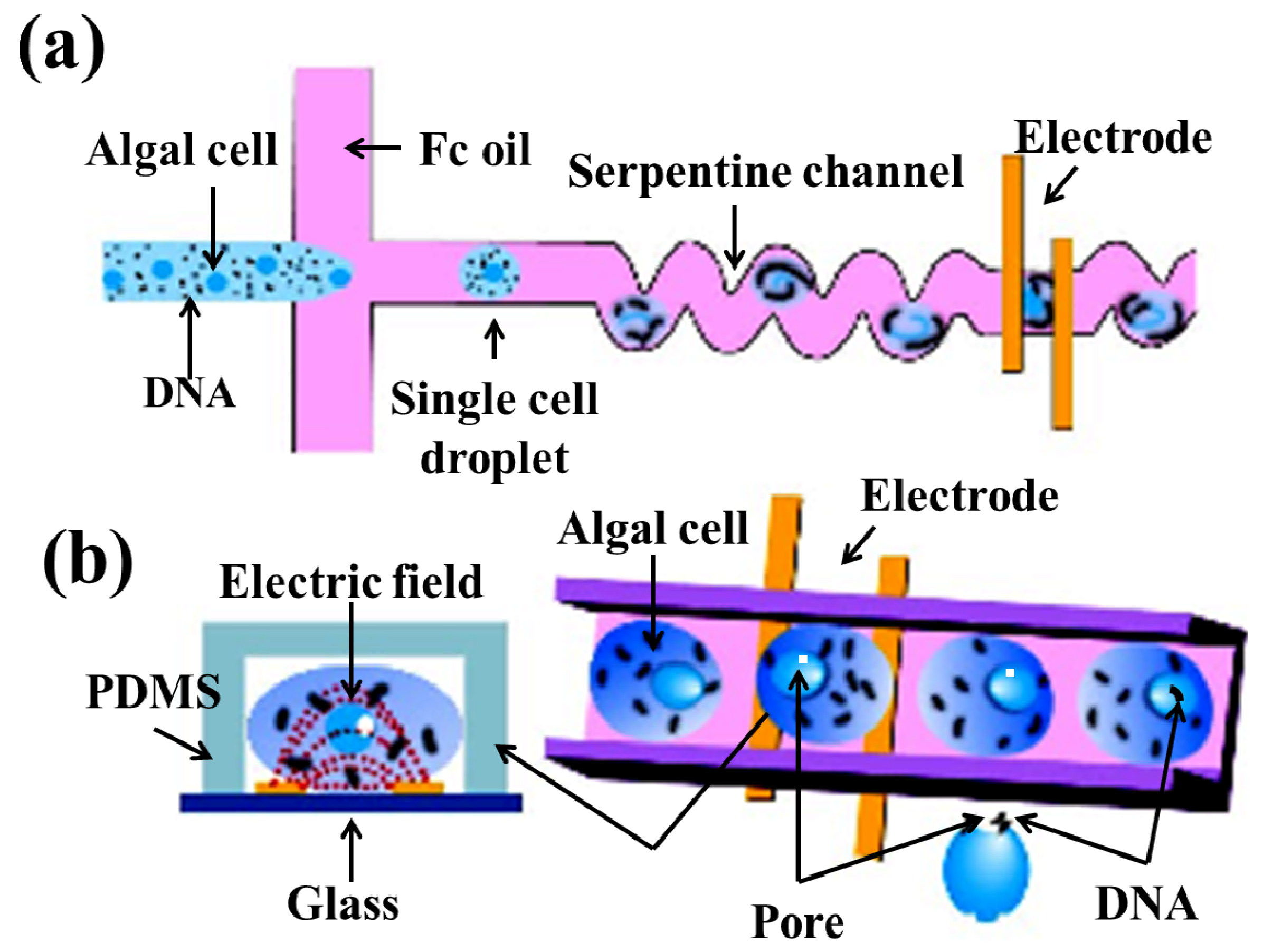
Recently, Qu et al. [76] proposed droplet electroporation with the use of microfluidic device. This device was fabricated with polydimethylsiloxane (PDMS) by using soft lithography process. Figure 9 shows the droplet microfluidic electroporation technique. Figure 9a,b shows a schematic of the droplet based microfluidic device and electroporation for algal cell. This device included two inlets and one outlet channel. One inlet channel contained DNA with algal cells whereas another inlet channel contained Fc oil. This cell content droplet flowed through the oil phase into the channel, where five pairs of micro-electrodes with constant DC voltage was present. A constant DC voltage with 1.3 V was applied to produce 393 V cm−1 electric field for electroporation experiment. The electric current act, when the conducting droplet buffer with the cell passed through the microelectrodes. Oil passing through the microelectrodes leads to zero current due to nonconductive oil solution.
The gap between two electrodes were 33 µm. The electroporation time can be controlled by controlling the droplet size, flow rate of droplet size with droplet content cells and DNA, flow rate of oil, etc. When the flow rate of the droplet containing cell and the flow rate of the oil were 0.3 µL min−1 and 0.5 µL min−1, the electroporation time was 7 ms. The ratio of the cell counting droplet was 70% when the concentrations of the cells were 1.58 × 10⁷ cells/mL. This device was achieved the transformation efficiency 8.14 × 10⁴ and cell viability 81% by using serpentine channel with five pairs of parallel electrodes on the chip with DNA/algal cell ratio of 1000. This chip provided very high transfection efficiency (1600 times higher than that (5.05 × 10⁻⁷) compared to the bulk electroporation process.
Figure 9.
Droplet microfluidic electroporation technique (a) schematic diagram; (b) electroporation process of algal cell. Figure has been redrawn from reference [76].
Figure 9.
Droplet microfluidic electroporation technique (a) schematic diagram; (b) electroporation process of algal cell. Figure has been redrawn from reference [76].

3.2. Single Cell Lysis
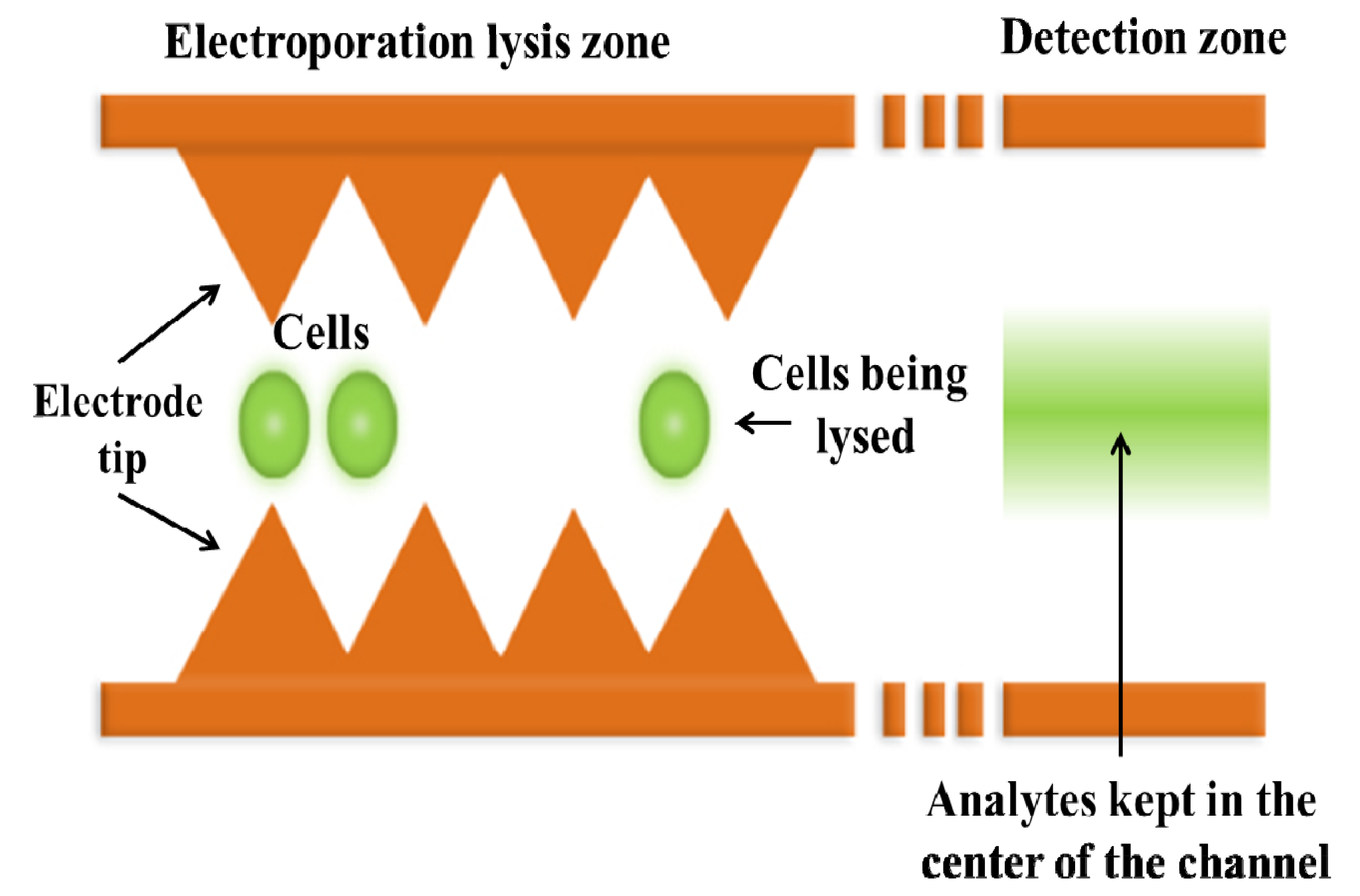
Microfluidic devices can provide single cell transfection as well as cell lysis by their unique design. Cell transfection can provide exogenous biomolecules delivery inside single cell with complete cell membrane resealing, which also known as reversible electroporation. This process can analyze intracellular biochemical effect and electrochemical cell membrane behavior. For irreversible electroporation, cell membrane cannot reseal due to high electric field affect and the membrane can rapture permanently resulting cell lysis. Both the processes have wide biological and therapeutic applications. Reversible electroporation or cell transfection can be applied to electrochemotherapy whereas irreversible electroporation or cell lysis can be applied to chemotherapeutic process. Figure 10 shows a microfluidic based single cell lysis device [88]. This device is designed with a continuous flow. The electric field strength was in periodic variation due to saw teeth geometry in each electrode. The overall channel was 1100 µm wide with 180 saw-teeth electrodes.
The distance between two electrodes tip was three times of the cell diameter to avoid cell clogging. Figure 10 shows the saw-teeth design of microelectrodes and electrical lysis zone in-between two electrodes. For this unique design of saw-teeth electrodes, the voltage requirement was very low and generation of heat was lower compared to bulk electroporation process. The results of this device shows that 81% cells were partially lysed where as 28% cells were completely lysed for 6 V, AC with 5 KHz frequency. Also, 74% cells became completely lysed and 71% cells were partially lysed for 8.5 V AC with 10 KHz frequency.
Figure 10.
Schematic representation of microfluidic cell lysis device where saw-teeth microelectrodes acting as a dielectrophoresis effect on the device for focusing intracellular material after electroporation. Figure has been redrawn from reference [88].
Figure 10.
Schematic representation of microfluidic cell lysis device where saw-teeth microelectrodes acting as a dielectrophoresis effect on the device for focusing intracellular material after electroporation. Figure has been redrawn from reference [88].

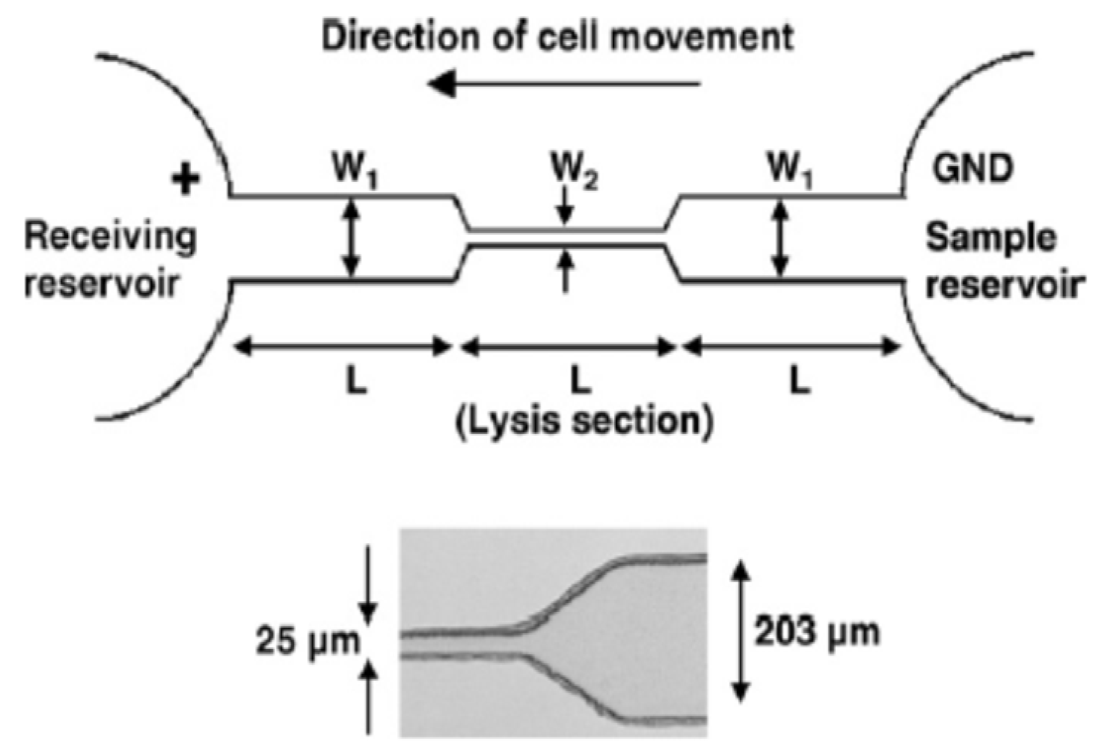
Figure 11.
Microfluidic based flow through electroporation device. Cells from sample reservoir moving to the receiving reservoir and electrical lysis were confined with single cell movement through the lysis section (W2). Permission to reprint obtained from Elsevier [71].
Figure 11.
Microfluidic based flow through electroporation device. Cells from sample reservoir moving to the receiving reservoir and electrical lysis were confined with single cell movement through the lysis section (W2). Permission to reprint obtained from Elsevier [71].

Another cell lysis device was proposed by Wang et al. in 2006 [71,89]. This microfluidic device was fabricated with PDMS by using the soft lithographic process. Figure 11 shows the microfluidic cell lysis device using electroporation technique. Initially, both reservoirs (sample reservoir and receiving reservoir) were filled with phosphate buffered saline. Then, cells were loaded in sample reservoir with 106 cells/mL concentration. Both reservoirs contained 30 µL solutions during experiment. Platinum electrodes were connected with two reservoirs where positive electrode was in the receiving reservoir and the negative electrode was in the sample reservoir. Due to high electric field application, cells were moved from sample reservoir to the receiving reservoir through lysis section. The dimension of cell lysis section was 25 µm to avoid cell clogging and ensure stable performance. This section has higher electric field strength (because of narrow section) compared to two reservoirs. The cell lysis rate can be varied due to changes of length and width of the two reservoirs and lysis section. They achieved 100% cell lysis for 1000–1500 V/cm electric field application. Also, they found complete cell membrane disruption in cell lysis section at 2000 V/cm electric field application.
Micro/nanofluidic devices have great ability to analyze the intracellular content after cell lysis by the application of sufficient external electric field. This device can detect and analyze the cell response based on laser induced fluorescence and electrophoresis methods [90,91,92,93,94,95]. Generally, many biomolecules (protein, metabolites) except nucleic acid cannot amplify. Thus, the fluorescence-based method can detect and analyze of single cell response with high sensitivity.
In 2007, Li et al. [94] proposed their microfluidic device for single cell analysis. The chip was fabricated by standard 1-photomask with low cost method. The device consists four reservoirs, four channels and one open region which contain a cell retention chamber. Reservoir one was used for cell introduction and washing, whereas reservoir two was used for reagent delivery. Reservoir three and four were used as waste reservoirs. By using this chip, they quantified dynamic Ca2+ mobilization of a single cardiomyocyte during its spontaneous contraction. Also, they monitored successfully dynamic responses from various external stimulation such as daunorubicin (cardiotoxic chemotherapeutic drug), caffeine, and isoliquiritigenin (herbal anticancer). Their results also prove that anticancer drugs have less effect on the Ca2+ of the cardiomyocytes. This device has quantified the cellular response of single cardiomyocytes, discovery of heart diseases drug and cardiotoxicity testing.
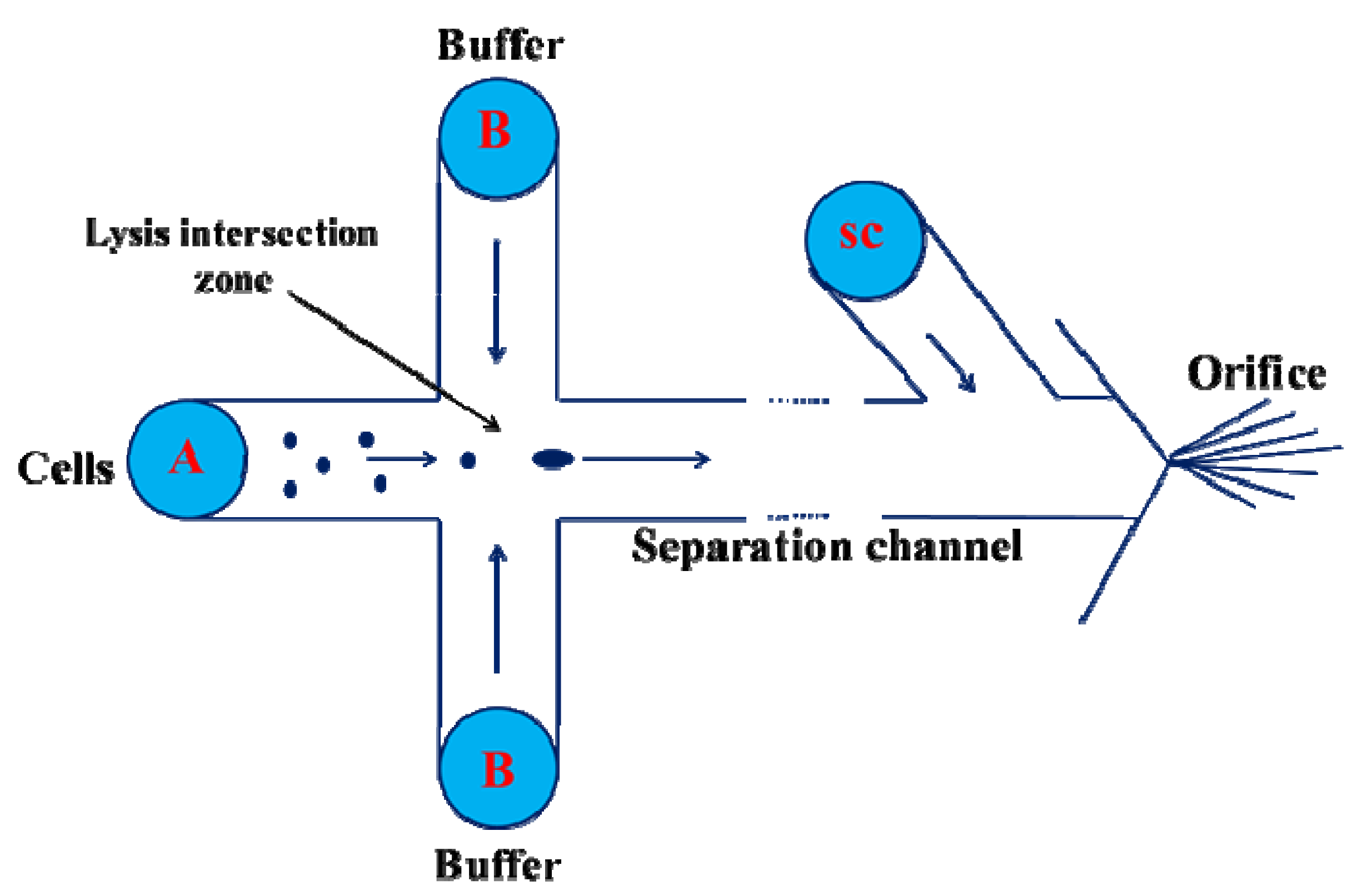
In 2010, Mellors et al. [95] proposed an electrophoretic and electrospray ionization based microfluidic device for single cell analysis. The device was fabricated on corning borosilicate glass substrate by using standard photolithography and wet chemical etching technique. Figure 12 shows the schematic of the microfluidic device, where A was a cell loading reservoir and B was buffer loading, which intersects with the separation channel.
Figure 12.
Schematic diagram for cell lysis using capillary electrophoresis and mass spectrometry. The arrow indicated direction of electroosmotic flow. Cells flow from cell reservoir (A) to the intersection zone where cells were lysed, then they migrate towards electrospray orifice through separation channel. Figure has been redrawn from reference [95].

This intersection zone was a cell lysis zone. CS was an electro-osmotic pump which was connected with an electrophoretic separation channel and electrospray orifice. Cells can flow through hydrodynamically or electrically to the intersection zone, where cells were electrically lysed. Then, cells can migrate to electrospray orifice through the separation channel where cells electrospray ionization occurred. This device successfully lysed human erythrocytes with real-time electrophoretic separation. The heme group, α and β subunits of hemoglobin were detected from erythrocytes when cells were continuously flowed through the device. This device can analyze 12 c/m.
4. Localized Single Cell Membrane Electroporation (LSCMEP)
4.1. LSCMEP for Cell Transfection
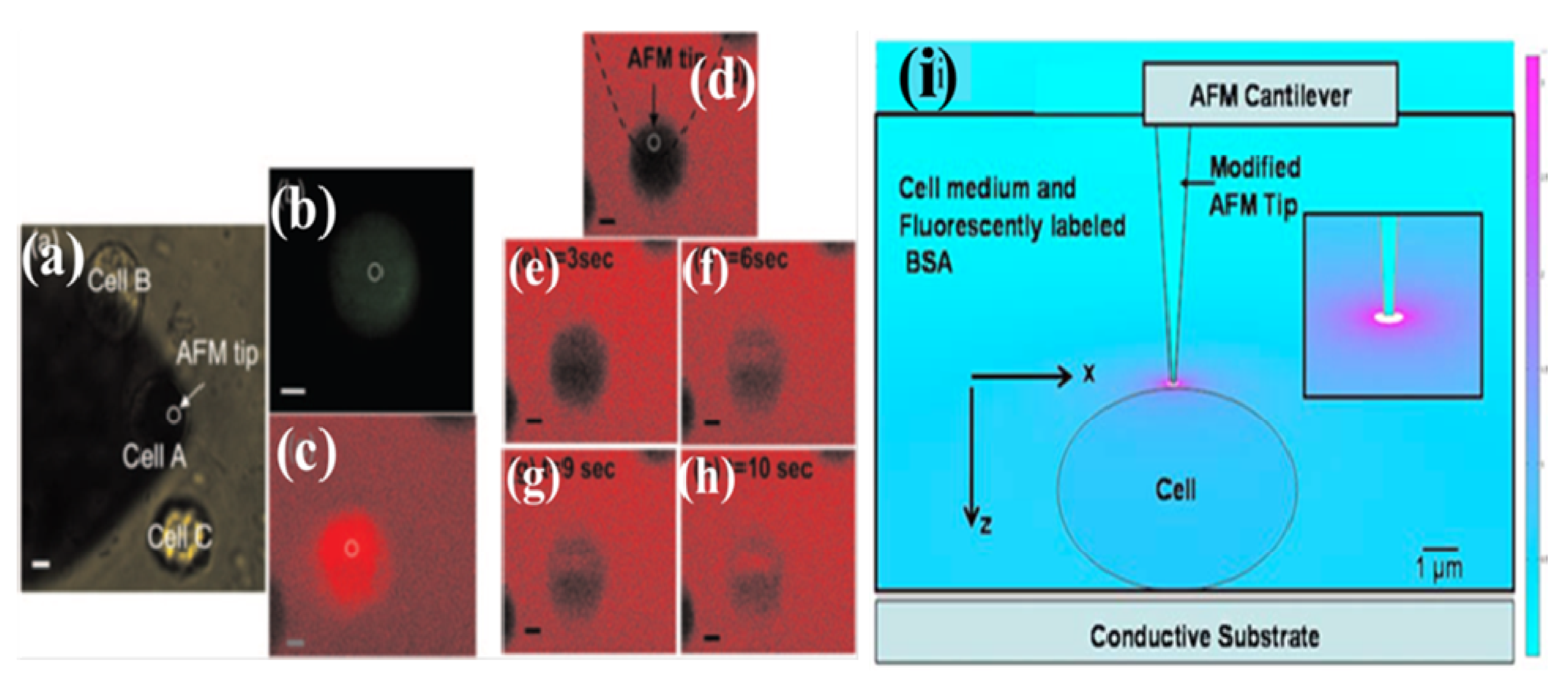
Localized single cell membrane electroporation can provide better cell transfection with micro/nanofluidic devices compared to single cell electroporation (SCEP) or bulk electroporation (BEP). Because of micro/nanoscale electrode dimension and distance between two electrodes were very small, as a result, electric field can intense in a very small region of the cell membrane compared to single cell dimension. Thus, the local area of the single cell can be affected by a strong electric field, whereas other areas will be unaffected. Due to the effects of small areas of the whole single cell, high cell viability and high transfection rate can be achieved compared to single cell electroporation. However, Boukany et al. show localized single cell electroporation by using nano-channel based ion transportation using electrophoresis method with two large electrodes [30]. By fabricating micro/nano electrodes with a micro/nano scale electrode gap, this device can provide some promising parameters such as low voltage and power requirement, lower toxic effect due to negligible ion generation, small sample volume and negligible heat generation. These parameters are essential to achieve high transfection rate and high cell viability. Thus, microfluidic based LSCMEP process can provide a better understanding to analyze intracellular cytosolic compounds compared to SCEP or the bulk electroporation process. Nawarathna et al., demonstrated the AFM based LSCMEP process. Figure 13 shows localized electroporation of a single cell using atomic force microscopy (AFM) technique [29]. For this experiment, they modified AFM tip to act as a nano-electrode to make an intense high electric field near the localized area of the single cell membrane. A boron doped silicon AFM tips (σ = 0.001 Ω cm, k = 1.5 N/m) was used for LSCMEP process. Before electroporation, the tip was grown with 20 nm SiO2 layer and finally this oxidized tip was sectioned until bare silicon was exposed by focused ion beam (FIB) technique. As a result, a smaller area of bare silicon can cause an intense high electric field on a single cell membrane. They have reduced this bare silicon area down to 0.5 µm in diameter, which was concentrated with an intense electric field on 10 µm diameter of rat fibroblast cell. Figure 13a–h shows the results of LSCMEP technique using AFM tip for electroporation process and Figure 13i demonstrated the AFM tip, which was positioned on top of the single cell for localized single cell membrane electroporation (LSCMEP) process. To make an intense high electric field, 1Vpp with 0.5 Hz pulse was used to transfect rat fibroblast cells. The transfection of single cell was completed within 10 s. This device can perform highly localized electroporation of a sigle cell with concentric electric field on local area of single cell membrane. The experiment can be performed in a friendly environment such as cell culture dishes, etc.
Figure 13.
(a) bright field image of atomic force microscopy (AFM) tip and the cell in the electroporation medium (cell A is electroporated while cell B and C are about 20 µm away from cell A); (b) Fluorescence image of rat fibroblast cell after electroporation; (c) Confocal fluorescence image of an electroporated cell; (d)–(h) Sequence of real time confocal fluorescence images of rat fibroblast cell after electroporation; (i) Calculated spatial distribution of electric field in the vicinity of the cell being electroporated. Permission to reprint obtained from American Institute of Physics (AIP) [29].
In recent years, Boukany et al. [30] showed nanochannel based localized single cell electroporation with a precise amount of biomolecules delivery. In this device, they positioned a single cell in one microchannel by optical tweezers and transfection agent was loaded to another microchannel. These two microchannels were connected by one nanochannel. To apply a very high electric field in between two microchannels, a transfection agent was delivered through the nanochannel using an electrophoretically driven process and finally drugs were delivered inside a single cell through a very small area of the cell membrane. In 2012, Chen et al. demonstrated another localized single cell membrane electroporation usimg ITO microelectrode based transparent chip [27]. Figure 14 shows microfluidic localized single cell membrane electroporation device. They deposited ITO films on a covered glass substrate and patterend it by standard lithographic process to form as ITO lines. After that, a thin SiO2 layer was deposited as a passivation layer by plasma enhanced chemical vapor deposition (PECVD) technique. The final ITO lines were cut by the focused ion beam (FIB) technique. The gap between two electrodes were 1 µm and width of each electrode was 2 µm. When single cell was strongly attached in between two electrodes gap, the electric field was intensed in only a 1 µm gap area on single cell membrane. As a result, they demonstrated localized single cell membrane electroporation with microfluidic device. Figure 14a shows localized electroporation process between two micro-electrodes and Figure 14b shows multiple number of electrodes for LSCMEP process. Figure 14 c and d shows the optical microscope image of patterened ITO microelectrodes and scanning electron microscope (SEM) image of ITO microelectrodse with micro-channel. According to their results, they achived 0.93 µm electroporation region with 60% cell viability for 8Vpp 20 ms pulse application. To reduce the gap between two electrodes, a high transfection rate can be achived by this technique. This device not only control the recovery of cell membranes (reversible electroporation) without cell damage but also it provides clear optical view by using an inverted microscope (ITO based transparent chip).
Figure 14.
Localized single cell membrane electroporation (LSCMEP) device (a) localized electroporation process between two microelectrodes; (b) multiple number of microelectrodes for LSCMEP process; (c) optical microscope image of ITO microelectrodes; (d) scanning electron microscope image of ITO microelectrodes with microchannel. Permission to reprint obtained from Springer [27].
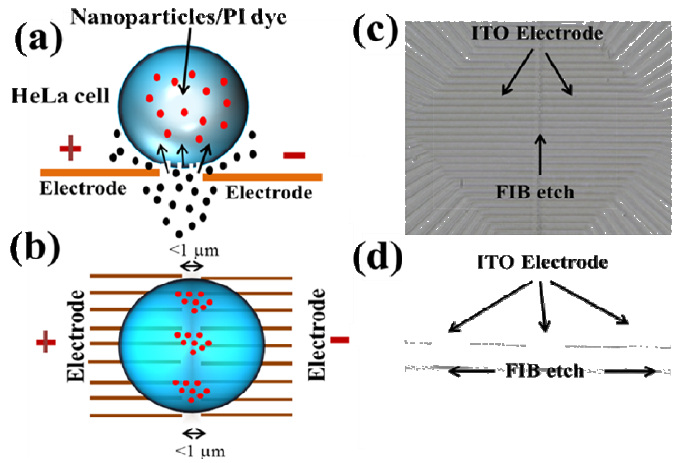
Figure 15.
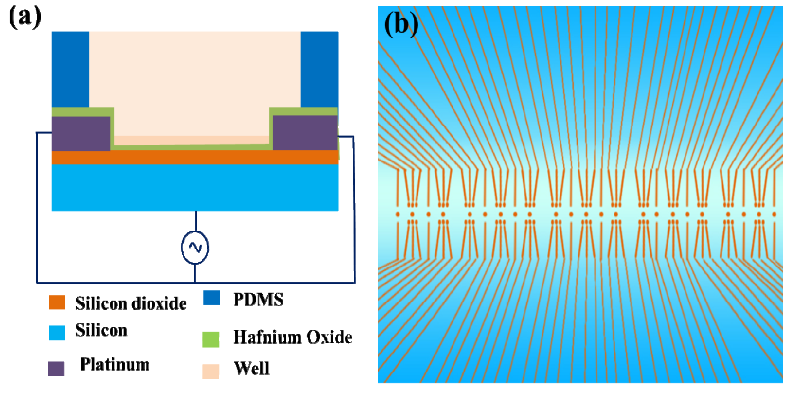
(a) Schematic diagram with electrical connection of the device and PDMS structure; (b) an array of transistors with nanowires and nanoribbons. Figure has been redrawn from reference [77].
Figure 15.
(a) Schematic diagram with electrical connection of the device and PDMS structure; (b) an array of transistors with nanowires and nanoribbons. Figure has been redrawn from reference [77].

4.2. LSCMEP for Cell Lysis
Recently, another LSCMEP based device was proposed by Jokilaakso et al. [77] for single cell lysis. They reported a silicon nanowire and nanoribbon based biological field effect transistor for single cell positioning and lysis mechanism. Figure 15a shows the cross sectional view and electric connection with PDMS above the device and Figure 15b shows an array of the transistors with both nanowires and nanoribons. To position the single cell on this device, they used programmable magnetic field for magnetic manipulation of 7.9 µm COOH modified COMPEL magnetic microsphere. After positioning the single cell (HT-29) on top of the transistor, cells were adhered for 30 min prior to electroporation experiment. The applied electric field was 600–900 mVpp (peak to peak) at 10 MHz for 2 ms pulse. This electric field was connected with a shorted source and drain in one terminal and another terminal connected on the gate of the device. The electric field intensity was fringing in nature, which affected the cell membrane integrity leading to cell lysis. This device can perform single cell lysis which is potentially applicable to medical diagnostics and biological cell studies.
5. Conclusions
In summary, this article describes the details about bulk electroporation (BEP), single cell electroporation (SCEP), and localized single cell membrane electroporation (LSCMEP) by using micro/nanofluidic devices with their advantages and disadvantages. All of these processes can deliver drugs, DNA, RNA, oligonucleotides, proteins, etc. However, to analyze cell to cell behavior with their organelles and intracellular biochemical effect, single cell analysis must be executed. Micro/nanofluidic devices are the potential candidates to analyze single cells, because of their dimension reduction to the dimension of single cell level. These devices provide easy performance such as cell handling, lower power consumption, low toxicity, small sample volume, lower contamination rate, high cell viability, and high transfection rate when compared to conventional electroporation. To reduce the electrode area and gap between two electrodes by using micro/nanofluidic devices, selective and localized drug delivery is possible. This new approach is called localized single cell membrane electroporation (LSCMEP). However, until now this technique is in the development stage. In the future, the LSCMEP process can provide selective and specific single cell manipulation from millions of populations of cells together. Micro/nanofluidic devices can approach this level in the near future, which will be potentially beneficial for medical diagnostics, proteomics analysis and biological studies.
Acknowledgements
The authors greatly appreciate for financial support from National Science Council (NSC) of Taiwan ROC through National Nanotechnology and Nanoscience Program under Contract no. (NSC-101-2221-E-007-032-MY3) and (NSC-101-2120-M-007-001).
Conflicts of Interest
The authors declare no conflicts of interest.
References
- Zimmermann, U.; Pilwat, G.; Friemann, F. Dielectric breakdown of cell membrane. Biophy. J. 1974, 14, 881–899. [Google Scholar] [CrossRef]
- Weaver, J.C.; Chizmadzhev, Y.A. Theory of electroporation: A review. Bioelectrochem. Bioenerget. 1996, 41, 135–160. [Google Scholar] [CrossRef]
- Teissie, J.; Golzio, M.; Rols, M.P. Mechanism of cell membrane electropermeabilization: A minireview of our present (lack of ?) knowledge. Biochim. Biophys. Acta. 2005, 1724, 270–280. [Google Scholar] [CrossRef]
- Escoffre, J.M.; Porter, T.; Wasungu, L.; Teissie, J.; Dean, D.; Rols, M.P. What is (still not) known of the mechanism by which electroporation mediates gene transfer and expression in cells and tissues. Mol. Biotechnol. 2009, 41, 286–295. [Google Scholar] [CrossRef]
- Neu, W.K.; Neu, J.C. Theory of Electroporation. In Cardiac Bioelectric Therapy; Efimov, I.R., Kroll, M.W., Tchou, P.J., Eds.; Springer: New York, NY, USA, 2009; pp. 133–134. [Google Scholar]
- Ho, S.Y.; Mittal, G.S.; Cross, J.D. Effect of high electric field pulses on the activity of selected enzymes. J. Food Eng. 1997, 31, 69–84. [Google Scholar] [CrossRef]
- Prasanna, G.L.; Panda, T. Electroporation: Basic principles, practical consideration and applications in molecular biology. Bioprocess Eng. 1997, 16, 261–264. [Google Scholar] [CrossRef]
- Serpersu, E.H.; Tsong, T.Y.; Kinosita, K. Reversible and irreversible modification of erythrocyte membrane permeability by electric field. Biochim. Biophys. Acta 1985, 812, 779–785. [Google Scholar] [CrossRef]
- Tsong, T.Y.; Kinosita, K. Use of voltage pulses for the pore opening and drug loading and the subsequent resealing of red blood cells. Bibliotheca Haematologica 1985, 51, 108–114. [Google Scholar]
- Schoenbach, K.H.; Beebe, S.J.; Buescher, E.S. Intracellular effect of ultrashort electrical pulses. Bioelectromagnetics 2001, 22, 440–448. [Google Scholar] [CrossRef]
- Chen, N.; Schoenbach, K.H.; Kolb, J.F.; Swanson, R.J.; Garner, A.L.; Yang, J.; Joshi, R.P.; Beebe, S.J. Leukemic cell intracellular responses to nanosecond electric fields. Biochem. Biophys. Res. Commun. 2004, 317, 421–427. [Google Scholar] [CrossRef]
- DeBruin, K.A.; Krassowska, W. Modelling electroporation in a single cell. I. Effects of field strength and rest potential. Boiphys. J. 1999, 77, 1213–1224. [Google Scholar] [CrossRef]
- DeBruin, K.A.; Krassowska, W. Modelling electroporation in a single cell. II. Effects of ionic concentrations. Biophys. J. 1999, 77, 1225–1233. [Google Scholar] [CrossRef]
- Movahed, S.; Li, D. Microfluidics cell electroporation. Microfluid Nanofluid 2011, 10, 703–734. [Google Scholar] [CrossRef]
- Chang, D.C.; Chassy, B.M.; Saunders, J.A. Guide to Electroporation and Electrofusion; Academic: San Diego, CA, USA, 1992. [Google Scholar]
- Tsong, T.Y. Electroporation of cell membranes. Biophys. J. 1991, 60, 297–306. [Google Scholar] [CrossRef]
- Neumann, E.; Sowers, A.E.; Jordan, C.A. Electroporation and Electrofusion in Cell Biology; Plenum Press: New York, NY, USA, 1989. [Google Scholar]
- Teissie, J.; Rols, M.P. An experimental evalution of the critical potential difference inducing cell membrane electropermeabilization. Biophys. J. 1993, 65, 409–413. [Google Scholar] [CrossRef]
- Zimmermann, U. Electric field-mediated fusion and related electric phenomena. Biochim. Biophys. Acta 1982, 694, 222–227. [Google Scholar]
- Stampfli, R. Reversible electric breakdown of the excitable membrane of a Ranvier node. Ann. Acad. Bras. Cien. 1958, 30, 57–63. [Google Scholar]
- Rubinsky, B. Irreversible electroporation in medicine. Technol. Cancer Res. Treat. 2007, 6, 255–259. [Google Scholar]
- Nollet, J.A. Researches Sur Les Causes Particulieres Des Phenomenes Electriques; (in French). Chez H.L. Guerin & L.F. Delatour: Paris, France, 1754. [Google Scholar]
- Fox, M.B.; Esveld, D.C.; Valero, A.; Luttge, R.; Mastwijk, H.C.; Bartels, P.V.; ven den Berg, A.; Boom, R.M. Electroporation of cells in microfluidic devices: A review. Anal. Bional Chem. 2006, 385, 474–485. [Google Scholar] [CrossRef]
- Lee, W.G.; Demirci, U.; Khademhosseini, A. Microscale electroporation: Challenges and perspectives for clinical applications. Integr. Biol. 2009, 1, 242–251. [Google Scholar] [CrossRef]
- Wang, S.; Lee, L.J. Micro-/Nanofluidics based cell electroporation. 2013, 7. [Google Scholar] [CrossRef]
- Wang, M.; Orwar, O.; Olofsson, J.; Weber, S.G. Single cell electroporation: Review. Anal. Bional. Chem. 2010, 397, 3225–3248. [Google Scholar] [CrossRef]
- Chen, S.-C.; Santra, T.S.; Chang, C.-J.; Chen, T.-J.; Wang, P.-C.; Tseng, F.-G. Delivery of molecules into cells using localized single cell electroporation on ITO microelectrode based transparent chip. Biomed. Microdevices 2012, 14, 811–817. [Google Scholar] [CrossRef]
- Kim, S.K.; Kim, J.H.; Kim, K.P.; Chung, T.K. Continuous low voltage dc electroporation on a microfluidic chip with polyelectrolytic salt bridges. Anal. Chem. 2007, 79, 7761–7766. [Google Scholar] [CrossRef]
- Nawarathna, D.; Unal, K.; Wickramasinghe, H.K. Localized electroporation and molecular delivery into single living cells by atomic force microscopy. Appl. Phys. Lett. 2008, 93, 153111. [Google Scholar] [CrossRef]
- Boukany, P.E.; Morss, A.; Liao, W.-C.; Henslee, B.; Jung, H.C.; Zhang, X.; Yu, B.; Wang, X.; Wu, Y.; Li, L.; et al. Nanochannel electroporation delivers precise amounts of biomolecules into living cells. Nat. Nanotecnol. 2011, 6, 747–754. [Google Scholar] [CrossRef]
- Weaver, J.C. Electroporation of cell and tissues. IEEE Trans. Plasma Sci. 2000, 28, 24–33. [Google Scholar] [CrossRef]
- Kinosita, K.; Hibino, M.; Itoh, H.; Shigemori, M.; Hirano, K.; Kirino, Y.; Hayakawa, T. Events of Membrane Electroporation Visualized on a Time Scale from Microsecond to Nanoseconds. In Guide to Electroporationand Electrofusion; Chang, D.C., Chassy, B.M., Saunders, J.A., Sowers, A.E., Eds.; Academic Press: Orlando, FL, USA, 1992; pp. 29–46. [Google Scholar]
- Neumann, E.; Rosenheck, R. Permeability induced by electric impulsions in vesicular membranes. J. Membr. Biol. 1972, 10, 279–290. [Google Scholar] [CrossRef]
- Gabriel, B.; Teissie, J. Direct observation in the millisecond time range of fluorescent molecule asymmetrical interaction with the electropermeabilized cell membrane. Biophys. J. 1997, 73, 2630–2637. [Google Scholar] [CrossRef]
- Lundqvist, J.A.; Sahlin, F.; Aberg, M.A.; Strimberg, A.; Eriksson, P.S.; Orwar, O. Altering the biochemical state of individual cultured cells and organelles with ultramicroelectrodes. Proc. Natl. Acad. Sci. USA 1998, 95, 10356–10360. [Google Scholar] [CrossRef]
- Valero, A.; Merino, F.; Wolbers, F.; Luttge, R.; Vermes, I.; Andersson, H.; van den Berg, A. Apoptotic cell death dynamics of HL 60 cells studied using a microfluidic cell tarp device. Lab Chip 2005, 5, 49–55. [Google Scholar] [CrossRef]
- Suehiro, J.; Yatsunami, R.; Hamada, R.; Hara, M. Quantitative estimation of biological cell concentration suspended in aqueous medium by using dielectrophoretic impedance measurement method. J. Phys. D Appl. Phys. 1999, 32, 2814–2820. [Google Scholar] [CrossRef]
- Suehiro, J.; Shutou, M.; Hatano, T.; Hra, M. High sensitive detection of biological cells using dielectrophoretic impedance measurement method combined with electropermeabilization. Sens. Actuators B 2003, 96, 144–151. [Google Scholar] [CrossRef]
- Suehiro, J.; Hatano, T.; Shutou, M.; Hra, M. Improvement of electric pulse shape of electropermeabilization-assisted dielectrophoretic impedance measurement for high sensitive bacteria detection. Sens. Actuators B 2005, 109, 209–215. [Google Scholar] [CrossRef]
- Loomis-Husselbee, J.W.; Cullen, P.J.; Irvine, R.F.; Dawson, A.P. Electroporation can cause artifacts due to solubilization of cations from the electrode plates. Biochem. J. 1991, 277, 883–885. [Google Scholar]
- Lin, Y.C.; Jen, C.M.; Huang, M.Y.; Wu, C.Y.; Lin, X.Y. Electroporation microchips for continuous gene transfection. Sens. Actuators B 2001, 79, 137–143. [Google Scholar] [CrossRef]
- Lin, Y.C.; Li, M.; Fan, C.S.; Wu, L.W. A microchip for electroporation of primary endothelial cells. Sens. Actuators A 2003, 108, 12–19. [Google Scholar] [CrossRef]
- Knorr, D.; Angersbach, A.; Eshtiaghi, M.N.; Heinz, V.; Lee, D. Processing concepts based on high intensity electric field pulses. Trends Food Sci. Technol. 2001, 12, 129–135. [Google Scholar] [CrossRef]
- Pol, I.E. Pulsed-electric field treatment enhances the bactericidal action of nisin against Bacillus cereus. App. Enviro. Microbial. 2000, 66, 428–430. [Google Scholar] [CrossRef]
- Fox, M.B.; Esveld, E.; Luttge, R.; Boom, R. A new pulsed electric field microreactor: Comparison between the laboratory and microscale. Lab Chip 2005, 5, 943–948. [Google Scholar] [CrossRef]
- Sedgwick, H.; Caron, F.; Monaghan, P.B.; Kolch, W.; Cooper, J.M. Lab-on-a-chip technologies for proteomic analysis from isolated cells. J. R. Soc. Interface 2008, 5, S123–S130. [Google Scholar] [CrossRef]
- De la Rosa, C.; Prakash, R.; Tilley, P.A.; Fox, J.D.; Kaler, K.V. Integrated microfluidic systems for sample preparation and detection of respiratory pathogen bordetella pertussis. Conf. Proc. IEEE Eng. Med. Biol. Soc. 2007, 2007, 6303–6306. [Google Scholar]
- Wang, J.; Bao, N.; Paris, L.L.; Wang, H.Y.; Geahlen, R.L.; Lu, C. Detection of kinase translocation using microfluidic electroporative flow cytometry. Anal. Chem. 2008, 80, 1087–1093. [Google Scholar] [CrossRef]
- Wang, H.Y.; Lu, C. Microfluidic electroporation for delivery of small molecules and genes into cells using a common DC power supply. Biotechnol. Bioeng. 2008, 8, 62–67. [Google Scholar]
- Olofsson, J.; Levin, M.; Stromberg, A.; Weber, S.G.; Ryttsen, F.; Orwar, O. Scanning electroporation of selected areas of adherent cell cultures. Anal. Chem. 2007, 79, 4410–4418. [Google Scholar] [CrossRef]
- Zudans, I.; Agarwal, A.; Orwar, O.; Weber, S.G. Numerical calculations of single-cell electroporation with an electrolyte-filled capillary. Biophys. J. 2007, 92, 3696–3705. [Google Scholar] [CrossRef]
- Agarwal, A.; Zudans, I.; Weber, E.A.; Olofsson, J.; Orwar, O.; Weber, S.G. Effect of cell size and shape on single-cell electroporation. Anal. Chem. 2007, 79, 3589–3596. [Google Scholar] [CrossRef]
- Olofsson, J.; Nolkrantz, K.; Ryttsen, F.; Lambie, B.A.; Weber, S.G.; Orwar, O. Single cell electroporation. Curr. Opin. Biotechnol. 2003, 14, 29–34. [Google Scholar]
- Ryttsen, F.; Farre, C.; Brennan, C.; Weber, S.G.; Nolkrantz, K.; Jardemark, K.; Chiu, D.T.; Orwar, O. Characterization of single cell electroporation by using patch-clamp and fluorescence microscopy. Biophys. J. 2000, 79, 1993–2001. [Google Scholar] [CrossRef]
- Nolkrantz, K.; Farre, C.; Brederlau, A.; Karlsson, R.I.; Brennan, C.; Erikssson, P.S.; Weber, S.G.; Sandberg, M.; Orwar, O. Electroporation of single cells and tissues with an electrolyte filled capillary. Anal. Chem. 2001, 73, 4469–4477. [Google Scholar] [CrossRef]
- Fei, Z.; Wang, S.; Xie, Y.; Henslee, B.E.; Koh, C.G.; Lee, L.J. Gene transfection of mammalian cells using membrane sandwich electroporation. Anal. Chem. 2007, 79, 5719–5722. [Google Scholar] [CrossRef]
- Fei, Z.; Hu, X.; Choi, H.-W.; Wang, S.; Farson, D.; Lee, L.J. Micronozzle array enhanced sandwich electroporation of embryonic stem cells. Anal. Chem. 2010, 82, 353–358. [Google Scholar] [CrossRef]
- Vassanelli, S.; Bandiera, L.; Borgo, M.; Cellere, G.; Santoni, L.; Bersani, C.; Salamon, M.; Zaccolo, M.; Lorenzelli, L.; Girardi, S.; et al. Space and time-resolved gene expression experiments on cultured mammalian cells by a single-cell electroporation microarray. New Biotechnol. 2008, 25, 55–67. [Google Scholar]
- Vally, J.K.; Hsu, H.-Y.; Neale, S.; Ohta, A.T.; Jamshidi, A.; Wu, M.C. Assessment of Single Cell Viability Following Light Induced Electroporation through Use of On-Chip Microfluidics. In Proceedings of the IEEE 22nd International Conference on Micro Electro Mechanical Systems, Sorrento, Italy, 25–29 January 2009; pp. 411–414.
- Valley, J.K.; Neale, S.; Hsu, H.-Y.; Ohta, A.T.; Jamshidi, A.; Wu, M.C. Parallel single-cell light-induced electroporeation and dielectrophoretic manipulation. Lab Chip 2009, 9, 1714–1720. [Google Scholar] [CrossRef]
- Brennan, D.; Justice, J.; Corbett, B.; McCarthy, T.; Galvin, P. Emerging optofluidic technologies for point-of-care genetic analysis systems: A review. Anal. Bioanal. Chem. 2009, 395, 621–636. [Google Scholar] [CrossRef]
- Lin, Y.-H.; Lee, G.-B. An optically induced cell lysis device using dielectrophoresis. Appl. Phys. Lett. 2009, 94, 033901. [Google Scholar] [CrossRef]
- Sott, K.; Eriksson, E.; Petelenz, E.; Goksor, M. Optical system for single cell analysis. Expert. Opin. Drug Discov. 2008, 3, 1323–1344. [Google Scholar] [CrossRef]
- Yang, S.-M.; Yu, T.-M.; Huang, H.-P.; Ku, M.-Y.; Hsu, L.; Liu, C.H. Dynamic manipulation and patterning of microparticles and cells by using TiOPc-based optoelectronic dielectrophoresis. Opt. Lett. 2010, 35, 1959–1961. [Google Scholar] [CrossRef]
- Yang, S.-M.; Yu, T.-M.; Huang, H.-P.; Ku, M.-Y.; Tseng, S.-Y.; Tsai, C.-L.; Chen, H.P.; Hsu, L.; Liu, C.-H. Light-driven manipulation of pico-bubbles on a TiOPc-based optoelectronic chip. Appl. Phys. Lett. 2011, 98, 153512. [Google Scholar] [CrossRef]
- Huang, Y.; Rubinsky, B. Micro-electroporation: Improving the efficiency and understanding of electrical permeabilization of cells. Biomed. Microdevice. 1999, 2, 145–150. [Google Scholar] [CrossRef]
- McClain, M.A.; Culbertson, C.T.; Jacobson, S.C.; Allabritton, N.L.; Sims, C.E.; Ramsey, J.M. Microfluidic devices for the high-throughput chemical analysis of cells. Anal. Chem. 2003, 75, 5646–5655. [Google Scholar] [CrossRef]
- Gao, J.; Yin, X.F.; Fang, Z.L. Intergation of single cell injection, cell lysis separation and detection of intracellular constituents on a microfluidic chip. Lab Chip 2004, 4, 47–52. [Google Scholar] [CrossRef]
- Shin, Y.S.; Cho, K.; Kim, J.K.; Lim, S.H.; Park, C.H.; Lee, K.B.; Park, Y.; Chung, C.; Han, D.-C.; Chang, J.K. Electrotransfection of mammalian cells using microchannel-type electroporation chip. Anal. Chem. 2004, 76, 7045–7052. [Google Scholar] [CrossRef]
- Wang, H.-Y.; Lu, C. Electroporation of mammalian cells in a microfluidic channel with geometric variation. Anal. Chem. 2006, 78, 5158–5164. [Google Scholar] [CrossRef]
- Wang, H.-Y.; Bhunia, A.K.; Lu, C. A microfluidic flow-through device for high throughput electrical lysis of bacterial cells based on continuous DC voltage. Biosens. Bioelectron. 2006, 22, 582–588. [Google Scholar] [CrossRef]
- Ikeda, N.; Tanaka, N.; Yanagida, Y.; Hatsuzawa, T. On-chip single-cell lysis for extracting intracellular material. Jpn. J. Appl. Phys. 2007, 46, 6410–6414. [Google Scholar] [CrossRef]
- Valero, A.; Post, J.N.; van Nieuwkasteele, J.W.; Ter Braak, P.M.; Kruijer, W.; van den Berg, A. Gene transfer and protein dynamics in stem cells using single cell electroporation in a microfluidic device. Lab Chip 2008, 8, 62–67. [Google Scholar] [CrossRef]
- Lim, J.K.; Zhou, H.; Tilton, R.D. Liposome rupture and contents release over coplanar microelectrodes arrays. J. Colloid Interface Sci. 2009, 332, 113–121. [Google Scholar] [CrossRef]
- Zhu, T.; Luo, C.; Huang, J.; Xiong, C.; Quyang, Q.; Fang, J. Electroporation based on hydrodynamic focusing of microfluidics with low DC voltage. Biomed. Microdevices 2010, 12, 35–40. [Google Scholar] [CrossRef]
- Qu, B.; Eu, Y.-J.; Jeong, W.-J.; Kim, D.-P. Droplet electroporation in microfluidics for efficient cell transformation with or without cell wall removal. Lab Chip 2012, 12, 4483–4488. [Google Scholar] [CrossRef]
- Jokilaakso, N.; Salm, E.; Chen, A.; Millet, L.; Guevara, C.D.; Dorvel, B.; Reddy, B., Jr.; Karlstrom, A.E.; Chen, Y.; Ji, H.; et al. Ultra-localized single cell electroporation using silicon nanowires. Lab Chip 2013, 13, 336–339. [Google Scholar] [CrossRef]
- Huang, Y.; Rubinsky, B. Microfabricated electroporation chip for single cell membrane permeabilization. Sens. Actuators A 2001, 89, 242–245. [Google Scholar] [CrossRef]
- Huang, Y.; Rubinsky, B. Flow through microelectroporation chip for high efficiency single cell genetic manipulation. Sens. Actuators A 2003, 104, 205–212. [Google Scholar] [CrossRef]
- Khine, M.; Lau, A.; Ionescu-Zanetti, C.; Seo, J.; Lee, L.P. A single cell electroporation chip. Lab Chip 2005, 5, 38–43. [Google Scholar] [CrossRef]
- Suzuki, T.; Yamamoto, H.; Ohoka, M.; Okonogi, A.; Kabata, H.; Kanno, I.; Washizu, M.; Kotera, H. High Throughput Cell Electroporation Array Fabricated by Single Mask Inclined uv Lithography Exposure and Oxygen Plasma Etching. In Proceedings of the IEEE 14th International Conference on Solid-State Sensors, Actuators, and Microsystems, Lyon, France, 10–14 June 2007; pp. 687–690.
- Ionescu-Zanetti, C.; Blatz, A.; Khine, M. Electrophoresis-assisted single-cell electroporation for efficient intracellular delivery. Biomed. Microdevic. 2008, 10, 113–116. [Google Scholar] [CrossRef]
- Gac, S.L.; van den Berg, A. Single cell electroporation using microfluidic devices. Methods Mol. Biol. 2012, 853, 65–82. [Google Scholar] [CrossRef]
- Koster, S.; Angile, F.E.; Duan, H.; Agresti, J.J.; Wintner, A.; Schmitz, C.; Rowat, A.C.; Merten, C.A.; Pisignano, D.; Griffiths, A.D.; et al. Drop-based microfluidic devices for encapsulation of single cells. Lab Chip 2008, 8, 1110–1115. [Google Scholar] [CrossRef]
- He, M.; Edgar, J.S.; Jeffries, G.D.M.; Lorenz, R.M.; Shelby, J.P.; Chiu, D.T. Selective encapsulation of single cells and subcellular organelles into picoliter- and femtoliter-volume droplets. Anal. Chem. 2005, 77, 1539–1544. [Google Scholar] [CrossRef]
- Luo, C.; Yang, X.; Fu, Q.; Sun, M.; Quyang, Q.; Chen, Y.; Ji, H. Picoliter-volume aqueous droplets in oil: Electrochemical detection and yeast cell electroporation. Electrophoresis 2006, 27, 1977–1983. [Google Scholar] [CrossRef]
- Zhan, Y.; Wang, J.; Bao, N.; Lu, C. Electroporation of cells in microfluidic droplets. Anal. Chem. 2009, 81, 2027–2031. [Google Scholar] [CrossRef]
- Lu, H.; Schmidt, M.A.; Jensen, K.F. A microfluidic electroporation device for cell lysis. Lab Chip 2005, 5, 23–29. [Google Scholar] [CrossRef]
- Wang, H.-Y.; Lu, C. High-throughput and real-time study of single cell electroporation using microfluidics: Effects of medium osmolarity. Biotechnol. Bioeng. 2006, 95, 1116–1125. [Google Scholar] [CrossRef]
- Li, X.Y.; Li, P.C.H. Microfluidic selection and retention of a single cardiac myocyte, on-chip dye loading, cell concentration by chemical stimulation, and quantitative fluorescent analysis of intracellular calcium. Anal. Chem. 2005, 77, 4315–4322. [Google Scholar] [CrossRef]
- Di Carlo, D.; Aghdam, N.; Lee, L.P. Single cell enzyme concentrations, kinetics, and inhibition analysis using high-density hydrodynamic cell isolation arrays. Anal. Chem. 2006, 78, 4925–4930. [Google Scholar] [CrossRef]
- Wheeler, A.R.; Throndset, W.R.; Whelan, R.J.; Leach, A.M.; Zare, R.N.; Liao, Y.H.; Farrell, K.; Manger, I.D.; Daridon, A. Microfluidic device for single-cell analysis. Anal. Chem. 2003, 75, 3581–3586. [Google Scholar] [CrossRef]
- Hargis, A.D.; Alarie, J.P.; Ramsey, J.M. Characterization of cell lysis events on a microfluidic device for high-throughput single cell analysis. Electrophoresis 2011, 32, 3172–3179. [Google Scholar] [CrossRef]
- Li, X.; Huang, J.; Tibbits, G.F.; Li, P.C. Real-time monitoring of intracellular calcium dynamic mobilization of a single cardiomyocyte in a microfluidic chip pertaining. Electrophoresis 2007, 28, 4723–4733. [Google Scholar] [CrossRef]
- Mellors, J.S.; Jorabachi, K.; Smith, L.M.; Ramsey, J.M. Integrated microfluidic device for automated single cell analysis using electrophoretic separation and electrospray ionization mass spectrometry. Anal. Chem. 2010, 82, 967–973. [Google Scholar] [CrossRef]
© 2013 by the authors; licensee MDPI, Basel, Switzerland. This article is an open access article distributed under the terms and conditions of the Creative Commons Attribution license (http://creativecommons.org/licenses/by/3.0/).
Share and Cite
MDPI and ACS Style
Santra, T.S.; Tseng, F.G. Recent Trends on Micro/Nanofluidic Single Cell Electroporation. Micromachines 2013, 4, 333-356. https://doi.org/10.3390/mi4030333
AMA Style
Santra TS, Tseng FG. Recent Trends on Micro/Nanofluidic Single Cell Electroporation. Micromachines. 2013; 4(3):333-356. https://doi.org/10.3390/mi4030333
Chicago/Turabian StyleSantra, Tuhin Subhra, and Fang Gang Tseng. 2013. "Recent Trends on Micro/Nanofluidic Single Cell Electroporation" Micromachines 4, no. 3: 333-356. https://doi.org/10.3390/mi4030333