Micromachined Thermal Flow Sensors—A Review

1
Department of Biomedical Engineering, University of Southern California, Los Angeles, CA 90089, USA
2
Ming Hsieh Department of Electrical Engineering, University of Southern California, Los Angeles, CA 90089, USA
*
Author to whom correspondence should be addressed.
Micromachines 2012, 3(3), 550-573; https://doi.org/10.3390/mi3030550
Submission received: 13 June 2012
/
Revised: 3 July 2012
/
Accepted: 16 July 2012
/
Published: 23 July 2012
(This article belongs to the Special Issue Micro Flow Controllers)
Abstract
:Microfabrication has greatly matured and proliferated in use amongst many disciplines. There has been great interest in micromachined flow sensors due to the benefits of miniaturization: low cost, small device footprint, low power consumption, greater sensitivity, integration with on-chip circuitry, etc. This paper reviews the theory of thermal flow sensing and the different configurations and operation modes available. Material properties relevant to micromachined thermal flow sensing and selection criteria are also presented. Finally, recent applications of micromachined thermal flow sensors are presented. Detailed tables of the reviewed devices are included.

1. Introduction
Micromachined flow sensors have great utility in a number of diverse applications requiring monitoring of gas [1] or fluid flow including flow cytometry [2], cleanroom environmental monitoring [3], wind [4], gas chromatography [5], wall shear stress [6], and viscosity measurements [7]. These sensors complement technologies such as microfluidic channels, valves, pumps, and heaters that are assembled together to create so-called lab on a chip (LOC) devices or micro total analysis systems (µTAS). As such, there has been great interest in their development in the microelectromechanical systems (MEMS) community since the first micromachined thermal flow sensor in 1974 [8,9,10].
Micromachined flow sensors can be classified as either thermal or non-thermal. Here, we focus on thermal flow sensors, which have been investigated extensively for their simple structure and implementation; a review of recent work is presented. Micromachining technology is amenable to creating microheaters and thermal sensors with no moving parts required, thus simplifying fabrication and operational design requirements. Another reason for the large interest in thermal flow sensors is the advantages gained through miniaturization: low power consumption, higher sensitivity to low flow rates, and ease of use with different modes of operation. In addition, thermal flow sensors can also detect thermal properties of fluids such thermal conductivity and thermal diffusivity when configured properly [11].
2. Theory
Thermal flow sensors rely on the ability of fluid flows to affect thermal phenomenon by way of heat transfer that, in turn, is transduced into a varying electrical signal capturing the sensor response to flow change. Ideally, sensors are thermally isolated so only heat transfer due to flow can occur. Other heat transfer pathways such as through substrate or electrical leads result in thermal losses that degrade sensor performance and should be minimized in the device design. Proper thermal flow sensor response is dependent upon a constant fluid temperature; temperature compensation must be implemented if fluid temperature will drift.
2.1. Thermal Flow Sensing Configurations
There are three forms of thermal flow sensing: hot-wire and hot-film, calorimetric, and time-of-flight [9].
2.1.1. Hot-Wire and Hot-Film
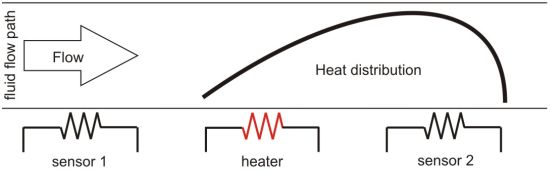
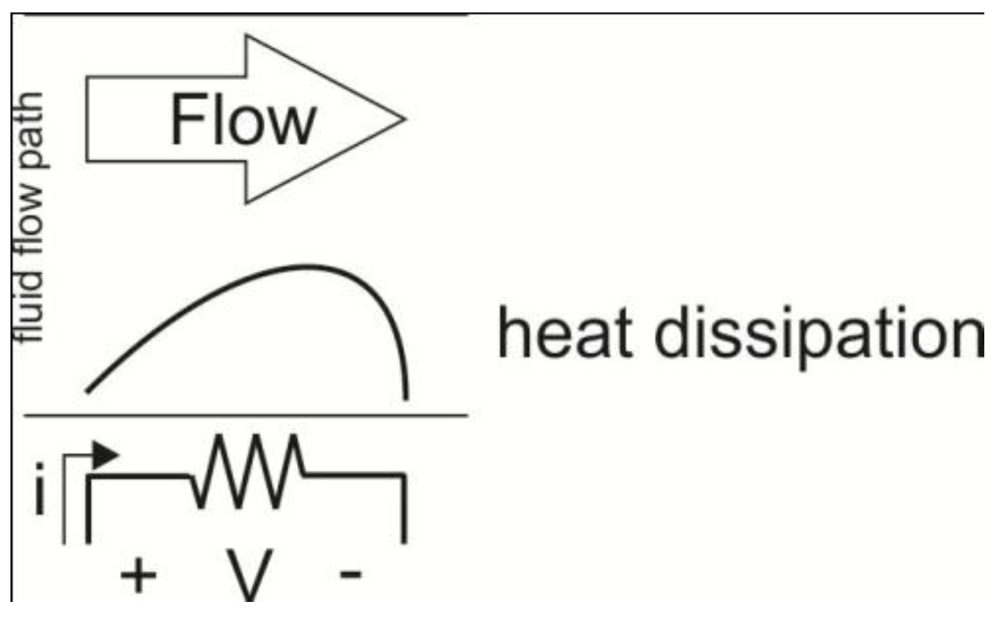
Hot-wire and hot-film sensors operate by heat transfer from a heated element to a surrounding cooler fluid (Figure 1). The term hot-wire implies the use of a resistive wire sensor element within the fluid flow whereas hot-film implies the use of a thin film resistive sensor that acts as the element placed adjacent to the flow. Regardless of their differences in form, both hot-wire and hot-film sensors share the same physical sensing principle. The sensing element is heated and subjected to fluid flow. As fluid flow past the element increases, convective heat loss increases from the heated element. The relationship between increasing fluid flow and forced convective cooling of the element can be determined and used as a baseline calibration for sensing applications. Appropriately selected sensor materials will experience a change in electrical resistance based upon change in temperature; thus heat transfer rate can be transduced into an electrical signal that changes with respect to fluid flow.
King’s Law describes heat transfer from a cylinder of infinite length in terms of the resulting voltage difference and is useful for hot-wire anemometry characterization [12]. The constants are a complex combination of fluid thermal conductivity properties and flow geometry and should be found empirically.
where:
- ∆V = flow induced voltage difference;
- v = velocity;
- a,b,n = constants.
For typical thermal flow sensor materials (Table 1), the resistance relationship to temperature is given by:

where R(T) is the resistance at temperature T and α is the temperature coefficient of resistivity (TCR). TCR can be determined experimentally by:
in which aR is the resistance overheat ratio and determined by measuring the change in resistance of the sensing material at two different temperatures.
Figure 1.
Illustration showing concept of hot wire anemometry. The resistor serves as a heater and sensing element. Resistance value is dependent on temperature.
Figure 1.
Illustration showing concept of hot wire anemometry. The resistor serves as a heater and sensing element. Resistance value is dependent on temperature.


Table 1.
Relevant electrical and thermal properties of thermal flow sensor materials [11].
| Material | Resistivity, ρ (Ω∙m) at 20 °C | TCR, α (10−4/K) |
|---|---|---|
| Aluminum | 2.69 × 10⁻⁸ | 42.0 |
| Copper | 1.67 × 10⁻⁸ | 43.0 |
| Gold | 2.30 × 10⁻⁸ | 39.0 |
| Iron | 9.71 × 10⁻⁸ | 65.1 |
| Nickel | 6.84 × 10⁻⁸ | 68.1 |
| Palladium | 10.8 × 10⁻⁸ | 37.7 |
| Platinum | 10.6 × 10⁻⁸ | 39.2 |
| Silver | 1.63 × 10⁻⁸ | 41.0 |
| Tungsten | 5.50 × 10⁻⁸ | 46.0 |
| Polysilicon | 4 × 10⁻⁶ [13]-1 × 101 [14,15,16] | −250–10 [14,15] |
The electrical and thermal properties of polysilicon are dopant dependent, which diffuse primarily across grain boundaries [13]. Conduction within a grain is similar to that of single crystal silicon with a positive TCR while conduction across grain boundaries exhibits negative TCR due to thermionic emission dominance [17]. Thus, the thermal and electrical properties of polysilicon can be tuned from a combination of grain size distribution, dopant concentration and type [13,15,17,18,19].
A high absolute TCR is desired for a thermal sensing material since sensitivity to temperature change is proportional to a material’s TCR. However, consideration of resistivity is also required since it is the resistance change that is being detected; a higher nominal resistance will increase sensitivity. Ease of material microfabrication processing needs to be balanced with TCR and resistivity considerations as well. Finally, consideration of how the sensor will be packaged and used will affect material selection. Sensors exposed to fluids may experience corrosion and low power may be required for use with volatile gases.
Of the commonly used materials for thermal flow sensors, platinum is worth highlighting; while this material does not possess the highest TCR its proven biocompatible property has made it a popular choice for biomedical flow sensing applications. Platinum is corrosion resistant, operates in high temperature range, compatible with standard micromachining techniques and used in many implantable devices [20,21,22,23,24,25].
Hot-wire and hot-film sensors are first characterized by imposing a known fluid flow and measuring the resulting resistance or voltage change of the sensors. It is important to note that the fluids used to characterize these sensors should be the same fluids used in measurements since the thermal conductive properties of the fluid are integral to the transduction mechanism. Fluids with similar thermal conductive properties may be substituted as well.
Six operational modes are possible with hot-wire and hot-film sensors by controlling the either the heater power or temperature and observing the heater temperature, power, or temperature difference resulting from fluid flow [9]. Constant heater power mode involves imposing a constant current bias on the heating element and monitoring the change in resistance or voltage due to flow. Constant temperature mode requires feedback circuitry that monitors and holds constant the sensor temperature; the increase in power required to maintain temperature under higher flow rates is monitored. While more complex in implementation, constant temperature mode can deliver better sensor resolution and frequency response [11].
One method of utilizing hot-wire and hot-film sensors is with a Wheatstone bridge. A single resistor can serve as both heater and sensor by placing it in a quarter-bridge configuration, where it acts as one of four resistors in a Wheatstone bridge [26]. A current source provides a current thereby heating the resistor. The Wheatstone bridge output is constantly monitored with a multimeter and any imbalance due to flow induced sensor electrical resistance change is measured.
2.1.2. Calorimetric
Calorimetric sensing involves at least one thermal sensor upstream and downstream the heating element that detect the thermal profile around the heater due to fluid flow. Thermal flow asymmetry due to fluid flow direction can be detected and thus this method allows for velocity measurements as opposed to flow (Figure 2).
For example, a simple one-dimensional model of a calorimetric sensor on silicon substrate heater temperature is [27]:
where:
- Th = heater temperature for constant heat power;
- P = heat power;
- kF = thermal conductivity of fluid;
- wh = heater width;
- lh = heater length;
- δ = boundary layer thickness;
- v = average flow velocity;
- a = thermal diffusivity of fluid;
![Micromachines 03 00550 i014]() dimensionless factor;
dimensionless factor;- kSi = thermal conductivity of silicon substrate;
- td = diaphragm thickness.
- The temperature difference between temperature sensors is given by:

where:
- ∆T = temperature difference;
![Micromachines 03 00550 i015]() ;
;- lu = distance to upstream sensor;
- ld = distance to downstream sensor.

Characterization with the fluid to be measured is required since the unique thermal conductivity properties of the fluid are essential to correct transduction of velocity to electrical signal.
Figure 2.
Illustration of calorimetric sensing concept.
2.1.3. Time-of-Flight
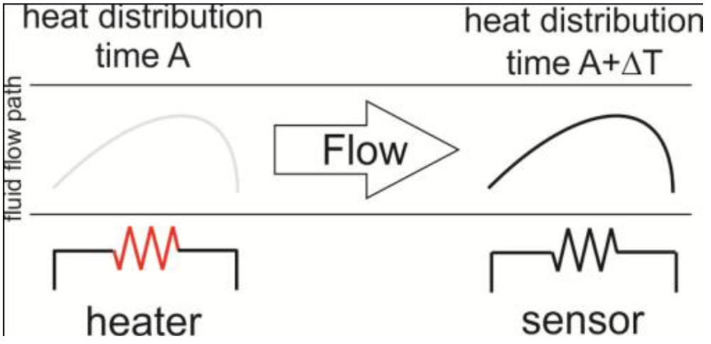
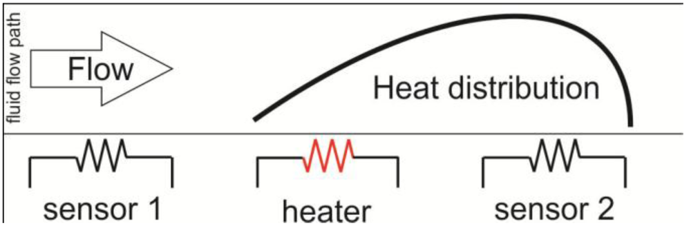
In time-of-flight sensing, the transit time of a thermal pulse is tracked to extract flow rate information. At least one heater and one downstream thermal sensor are required. A short thermal pulse is transferred from the heater to the surrounding fluid flow. Ideally, the heater is thermally isolated from the substrate to eliminate interference from thermal conduction effects. The downstream thermal flow sensor detects the thermal pulse (Figure 3).
The time between heat pulse generation and downstream detection is determined by several factors: the thermal conductivity and diffusivity of the fluid, heater-sensor distance ratio, and average flow velocity. Approximating the heater as a line source, the thermal distribution of the pulse as a function of distance and time can be described as [27]:
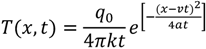
where
- T = temperature distribution at time t;
- x = distance from heater;
- t = time;
- q0 = pulse signal input strength;
- k = thermal conductivity of fluid;
- v = average flow velocity;
- a = thermal diffusivity.
Figure 3.
Illustration showing concept of time-of-flight sensing.

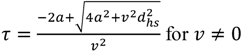
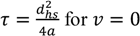
Flow velocity is calculated from the time and distance between heater and sensor, dhs:

Thermal diffusion in addition to forced convection is dominant in microflow and so needs to be taken into account. Thus, the time is given by:
As before, characterization with the fluid to be measured by imposing a known flow rate is required since fluid heat transfer properties determine relationship between detected signal and flow.
2.2. Thermal Flow Sensing Transduction Principles
Micromachined thermal flow sensors can be categorized into different types depending on their physical transduction method and materials [9]. Thermoresistive sensors utilize resistive elements for thermal sensing. Thermoelectric sensors detect thermal changes using thermopiles. In contrast, diode and transistor elements are used in thermoelectric sensing. Changes in resonant frequency within mechanical structures due to temperature change induced stress are utilized for frequency analog sensors.
2.2.1. Thermoresistive/Thermoanemometers
Thermoresistive or thermoanemometer sensors work by heat transfer away from a resistive element that is heated. As the resistor cools, the corresponding change in voltage or current can be calibrated to fluid flow. Resistors can also be used as thermal sensors without heating; the change in fluid temperature is also detected as a change in resistance, which alters the voltage or current flowing through it. These are by far the most popular types of micromachined flow sensors due to the ease of fabrication and operation (typical example in Figure 4).
Figure 4.
Micromachined Pt resistor used for thermoresistive flow sensing [28].
Figure 4.
Micromachined Pt resistor used for thermoresistive flow sensing [28].

2.2.2. Thermoelectric
Thermopiles, made up of several connected thermocouples, are used as the sensing element and operated in conjunction with a heater element for thermoelectric sensing. The fabrication of such sensors is more complicated since less conventional materials are utilized for fabrication of thermopiles but CMOS (complementary metal oxide semiconductor) compatible processing is possible (Table 2). The Seebeck effect of thermopiles enables higher sensitivity and unbiased output voltage with no offset or drift [29,30].
| Material | Seebeck coefficient (µV/K) at 0 °C | Thermal conductance (W/K∙m) |
|---|---|---|
| Aluminum | −1.7 1 | 237 |
| Chromium | 18.8 | |
| Gold | 1.79 | 318 |
| Copper | 1.70 | |
| Platinum | −4.45 | |
| Nickel | −18.0 | 90 |
| Bismuth | −79 1 | |
| Antimony | 43 2 | |
| p-type silicon | 300–1,000 1 | 149 |
| n-type silicon | −500–−200 1 |
1 At 27 °C. 2 Averaged over 0 to 100 °C.
The output voltage of a thermocouple is given by:

where:
- aa = Seebeck coefficient of material a;
- ab = Seebeck coefficient of material b;
- aab = Seebeck coefficient of thermocouple;
- Thot = Hot junction temperature;
- Tcold = Cold junction temperature;
- ∆Thot-cold = Temperature difference between hot and cold junction.
Thermopiles are constructed with thermocouples in series and so the output voltage due to temperature change is summed and increased over that of a single thermocouple. However, thermal conduction between hot and cold junctions and Johnson noise increases with increasing number of thermocouples, thereby degrading sensor performance. For increased sensitivity, high thermal isolation is desired in order to maximize temperature difference between hot and cold junctions. Thus, optimization of thermocouple number per thermopile should be taken into consideration.
Semiconductor thermopiles are more sensitive than metal thermopiles because of their higher Seebeck coefficients that are tuned with dopant type and concentration. Thermopiles can be any combination of materials and a figure of merit [31,33] for material combination optimization can be used to predict thermopile performance. Thermopiles fabricated from polysilicon and metals are commonly used in thermoelectric flow sensing.
2.2.3. Thermoelectronic
Transistors and diodes are used as thermal sensing elements in thermoelectronic sensors. The I–V relationship for a p-n junction is [34]:
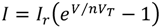
where:
- I = Current;
- Ir = Reverse saturation current;
- V = Voltage;
- n = Ideality factor; 2 for Si and 1 for Ge;
- VT = Volt equivalent of temperature.
In the case where I is constant across the junction:
where:
- m = 1.5 for Si and 2 for Ge;
- Vg = Forbidden-gap energy.
Empirically, it has been found that at room temperature (300 K) for both Si and Ge:
for maintaining a constant current across the p-n junction. In practice, King’s Law [35] can be used to characterize the effect of flow on diode or transistor signal output.
Thermoelectronic sensors are compatible with CMOS fabrication. Thus, integrated circuits for signal processing and amplification can be included on the same device without separate packaging.
2.2.4. Frequency Analog
Thermal sensing is realized by the use of mechanical structures such as cantilevers or surface acoustic wave (SAW) oscillators in frequency analog sensors. The resonant frequency of the structure changes in response to temperature change due to mechanical stress, described by the equations below [36].

- α = temperature coefficient of frequency (TCF) of a SAW device
- Ts = change in temperature due to an incremental change in flow rate.
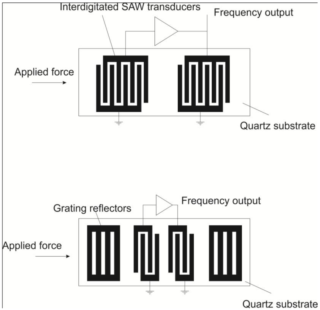
The resonant frequency is monitored and used to transduce flow rate in configurations analogous to calorimetric [37], time-of-flight [37], and hot-film [36,38] thermal flow sensors (Figure 5). Fabrication processes for resonant mechanical structures is well established, utilizing standard photolithographic techniques. While thermoresistive devices rely on constant power draw to induce heating, capacitive sensing options [39] for SAW based sensing result in comparatively reduced power draw.
Figure 5.
Frequency analog device, analogous modes of operation [37].
Figure 5.
Frequency analog device, analogous modes of operation [37].

However, fabrication of SAW transducers requires less common piezoelectric materials, thus limiting integration with CMOS devices and placing potential constraints on the intended operating environment.
3. Recent Applications of Micro-Thermal Flow Sensors
3.1. Thermoresistive
Nickel resistors have been used for flow sensing due to their high TCR (Figure 6) [40,41]. Kaanta et al. used Cr/Ni resistors over a suspended silicon nitride membrane to create an array of flow sensors for micro-gas chromatography systems [5]. Sensing flow at multiple points through an array of sensors allows for tracking of an analyte plug as it passes through the system [42].
Polysilicon has been investigated as a thermal flow sensor material [43]. Soundararajan et al. used phosphorous doped polysilicon resistors as heaters in hot-wire mode on a silicon nitride diaphragm. Constant temperature mode was utilized and sensor characterization took place within a PDMS microchannel [44]. Wu et al. used boron-doped polysilicon as heaters embedded into silicon nitride walls of a microchannel. Low flow rates of 10 nL/min were detected due to increased TCR of polysilicon due to boron doping [45].
Figure 6.
Nickel resistors arranged in bridge formation for air flow sensing on Si3N4 membrane for thermal isolation [41].
Figure 6.
Nickel resistors arranged in bridge formation for air flow sensing on Si3N4 membrane for thermal isolation [41].

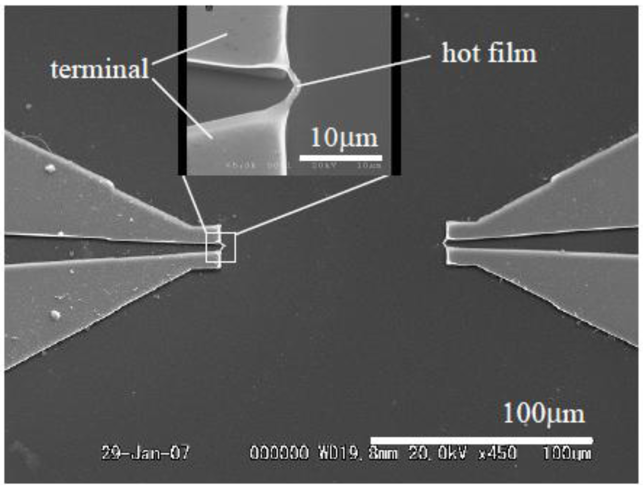
Figure 7.
Pt nanoscale suspended wire for hot-wire thermal flow sensing [46].
Figure 7.
Pt nanoscale suspended wire for hot-wire thermal flow sensing [46].

Platinum (Pt) resistors have been extensively used in thermal flow sensing (Table 3). Bailey et al. fabricated a nanoscale Pt hot-wire that measured 100 nm × 2 µm × 60 µm (Figure 7). The small dimensions led to better spatial and frequency responses compared to traditional anemometers [46]. Ito et al. added carbon nanotubes to Pt resistors to enhance heat transfer due to flow, thereby increasing sensor sensitivity [28]. Meng et al. used an array of Pt resistors and were able to compare hot-film, calorimetric, and time-of-flight sensor response on the same device. Multiple modes of operation extended the range of the device with constant temperature mode giving a better response over constant current [47]. Later, arrays of Pt resistors were used for neurotransmitter delivery [26,48]. Berthet et al. utilized time-of-flight through Pt sensors suspended in between microchannels created by the bonding of two etched Pyrex wafers [49]. Pt sensors were placed over suspended silicon nitride membranes for increased thermal isolation [50,51,52]. Even better thermal isolation can be obtained by creating a vacuum sealed cavity underneath the membrane while temperature is sensed above as used by Liu et al. and Hsiai et al. [53,54]. SU-8 can also be used for thermal isolation of Pt resistors due to its low thermal conductivity of 0.2 W/mK [55,56].
Figure 8.
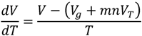
Diagram of flow device with integrated thermoresistors for thermal flow sensing and cantilevers for dual mode flow sensing; flow speed is thermally sensed and flow direction is physically sensed by cantilever deflection [57].
Figure 8.
Diagram of flow device with integrated thermoresistors for thermal flow sensing and cantilevers for dual mode flow sensing; flow speed is thermally sensed and flow direction is physically sensed by cantilever deflection [57].
Wind sensors have been created with thermoresistive technology [58]. Domínguez et al. created a wind sensor for use in Martian atmosphere on a space probe. Pyrex structures were used to maximize thermal isolation to increase sensor sensitivity since Martian pressure is very low (6 mbar) which impedes heat convection compared to normal atmosphere [59]. 3-dimensional MEMS structures have been used for wind sensing [60]. Ma et al. implemented a temperature compensation scheme through a RTD to compensate for temperature variations in air as it flowed over their device. Interestingly, piezoresistors on cantilevers were integrated into the device for flow sensing through physical transduction as well (Figure 8) [57].
Polymer substrates have been used to create flexible sensors that can be placed on curved surfaces [61,62,63]. Ahrens et al. created sensors for sensing possible leakage in piston systems using a polymer substrate. Flow pulsations of 1,200 Hz were detected and sensors could withstand high pressures of up to 100 bar [64,65]. Li et al. fabricated flow and glucose sensors on Kapton tape which were then rolled and fitted into catheters for eventual use in measuring blood flow. Different concentrations of glucose dissolved into PBS were used for characterization to mimic in vivo changes in blood viscosity and sensor performance was found to differ by less than 1.07% at the tested flow rate range, with compensation for drift [66,67,68]. Yu et al. created a flexible sensor on Parylene C polymer substrate for use in measuring rabbit arterial blood flow. The sensor was packaged to an electrically conductive catheter and inserted into the arterial walls of live rabbits where dynamic pulsatile blood flow was measured. Rabbit blood was used for benchtop characterization of the sensor through a PDMS flow channel before in vivo implantation [69,70,71,72,73,74,75].
| Material | Configuration | Gas/liquid | Resolution | Sensitivity | Range | Power Consumption | References |
|---|---|---|---|---|---|---|---|
| Ni | Calorimetric | N2 gas | 40 mV/SLM | 0–20sccm up to 8 SLM | N. Sabaté [40] | ||
| Si3N4 | |||||||
| Ni | Hot-film | Air | <1% | 0–20 m/s | 50 mW | Adamec [41] | |
| Si3N4 | Calorimetric | ||||||
| Pt | Hot-wire | N2 gas | 0–3 m/s | Ito [28] | |||
| CNT for enhanced heat transfer | |||||||
| Ti/Pt | Hot-film | DI H2O | 250 nL/min | 0–1 µL/min | Kuo [26] | ||
| Parylene | |||||||
| W/Ti/Pt | Hot-film | DI H2O | 0.5 µL/min | 25.1–3.92 × 10⁴ μV/(μL/min) | 0–400 µL/min | 3.3–23.5 mW | Meng [47] |
| Parylene | Calorimetric | ||||||
| Time-of-flight | |||||||
| Si | Calorimetric | Water | 0–10 mL/min | 600 mW | Nguyen [43] | ||
| Si3N4 | N2 gas | ||||||
| Pt | Time-of-flight | Hexadecane | 10–10,000 µL/min | 3.3 W | Berthet [49] | ||
| Pyrex | IPA | ||||||
| Polysilicon | Hot-film | Air | 0–30 m/s | Liu [54] | |||
| Si3N4 | |||||||
| Pt | Calorimetric | Air | Heater power dependent | Heater power dependent | 0–4 m/s | 2–20 mW | Fürjes [50] |
| Si3N4 | |||||||
| Pt | Hot-film | CO2 gas | 0.3 m/s | 0–20 m/s | 14 mW | Domnguez [59] | |
| Pyrex | |||||||
| Au | Hot-film | N2 gas | 10 mL/min | 0–200 mL/min | Ahrens [64] | ||
| Polyimide | Water | 10 µL/min | 3–167 µL/min | ||||
| Au | Hot-film | Oil | 0–90 L/min | Ahrens [65] | |||
| Polyimide | |||||||
| Pt | Calorimetric | Air | 0–32 m/s | Ma [57] | |||
| Au | |||||||
| Si3N4 | |||||||
| Ti/Pt | Calorimetric | Air | 0.3 m/s | 0–8 m/s | 100 mW | Shen [58] | |
| Ceramic | |||||||
| Ti/Au | Hot-film | Glucose/PBS (0–60%) | 3.06 mV/(mL/min) | 0–10 mL/min | <5 mW | Li [66] | |
| Kapton | |||||||
| Ti/Au | Hot-film | Glucose/DI H2O | 5 mL/100 gram-min | 1.467 mV/mL/100 gram-min | 0–160 mL/100 gram-min | Li [67] | |
| Cu | |||||||
| Parylene | |||||||
| Ti/Pt | Hot-film | Air | CV 2V: 0.01433 mA (m/s)−1/2 | 0–11 m/s | CV 2V: 14.56 mW | Hung [51] | |
| Si3N4 | CV 4V: 0.04593 mA (m/s)−1/2 | CV 4V: | |||||
| CC 12.96mA: 7.98 mV (m/s)−1/2 | 50.83 mW | ||||||
| CC 23.08mA: 27.35 mV (m/s)−1/2 | CC 12.96mA: | ||||||
| 45.10 mW | |||||||
| CC 23.08 mA: | |||||||
| 157.61 mW | |||||||
| Cr/Pt/Ni/Pt | Hot-wire | Air | Heater power dependent | Heater power dependent | Heater power dependent | Heater power dependent | Chen [60] |
| Polyimide | |||||||
| Cr/Au | Hot-film | N2 gas | 0–6 m/s | Tan [61,62] | |||
| Polyimide | |||||||
| Cr/Ni/Pt | Hot-film | Air | 0.1 m/s | 0–15 m/s | 30 mW | Liu [63] | |
| Polyimide | |||||||
| Pt | Hot-wire | Air | 7–40 m/s | Bailey [46] | |||
| Cr/Ni | Hot-wire | N2 gas | 0.002 m/s | 0–1.6 m/s | Kaanta [42] | ||
| Si3N4 | |||||||
| Polysilicon | Hot-wire | 0.2–0.5 mL/min | Soundararajan [44] | ||||
| Si3N4 | |||||||
| Polysilicon | Hot-wire | Cell medium | Hsiai [53] | ||||
| Silicon dioxide and Si3N4 | |||||||
| Ti/Pt | Hot-film | Rabbit blood | Non-linear | 0.35 mV/(dynes/cm2) | Yu [70,71] | ||
| Parylene | |||||||
| Polysilicon | Hot-film | DI H2O | 10 nL/min | 3.6–361.2 μV/(nL/min) | 0–650 nL/min | 140 µW | Wu [45] |
| Si3N4 | |||||||
| Germanium | Calorimetric | DI H2O | 100 nL/h | 0–90 µL/h | 1 mW | Ernst [76] | |
| Chromium heater | |||||||
| Germanium | Calorimetric | Air | <1 cm/s | 12.99–232.77 V/W/(m/s) | 0–5 m/s | 0.25–5.8 mW | Cubukcu [77] |
| Si3N4 | |||||||
| SiOx | |||||||
| Ti/Pt | Hot-wire | N2 gas | 3.76 mΩ/(m/s) | 0–10 SLPM | Kaltsas [55] | ||
| SU-8 | Calorimetric | ||||||
| Ti/Pt | Calorimetric | DI H2O | 40 nL/min | 485 µV/( µL/min) | 0–6 µL/min | 0–20 mW | Vilares [56] |
| SU-8 | IPA | ||||||
| Pt | Calorimetric | Water | 0.2 µL/min | 218 µV/( µL/min) | 0–2 µL/min | 1.9 mW | Dijkstra [52] |
| Silicon-rich silicon nitride |
Ernst et al. fabricated amorphous germanium on a silicon nitride membrane. Amorphous germanium was chosen for its high TCR (~2%/°K) while chromium was used as a heater for its low TCR (0.214%/°K) [76]. Cubukcu et al. also utilized amorphous germanium thermistors with TCR of 358.1 × 10⁻⁴/°K to achieve a sub-mW powered flow sensor that still possessed high flow sensing range up to 5 m/s [77].
3.2. Thermoelectric
Kaltsas et al. fabricated thermopiles from polysilicon and aluminum (Al). Thermopile hot contacts were placed close to the polysilicon heater while cold contacts were placed on the silicon substrate. A 40 µm porous silicon layer was used for thermal isolation on top of which the thermopile hot contacts and heater were fabricated [29,78,79,80].
Others have fabricated thermoelectric flow sensors using more conventional silicon nitride and oxide materials for thermal isolation (Figure 9) [81,82,83].
Bruschi et al. created thermopiles in a pseudo-calorimetric fashion over a silicon oxide membrane. Two thermally isolated heaters instead of one were used in between two thermopiles and thermal feedback maintained equal temperature between the two heaters under varying flow conditions [84,85,86].
In addition to silicon-based devices, thermopiles supported on polymers have been investigated for flow sensing applications in which a flexible substrate is desired (Table 4). Buchner et al. utilized a thin, flexible polyimide substrate to fabricate thermopiles and a heater in a calorimetric configuration [30,87].
| Material | Configuration | Gas/liquid | Resolution | Sensitivity | Range | Power Consumption | References |
|---|---|---|---|---|---|---|---|
| Polysilicon/Al Porous Si | Calorimetric | N2 gas | 4.1 × 10⁻³ m/s | 0.4 mV/(m/s) | 0–0.4 m/s | 67 mW | Kaltsas [29] |
| Polysilicon/Al Porous Si | Calorimetric | N2 gas | ~0.5 m/s | 175 × 10−3 mV/(m/s)1/2 | 0–4 m/s | Kaltsas [78] | |
| Polysilicon/Al Porous Si | Hot-wireCalorimetric | Not stated | 0.95 mV/(m/s)1/2 | 0–6.67 m/s | 100 mW for hot-wire | Kaltsas [79] | |
| Polysilicon/Ti-Tungsten | Calorimetric | WaterIPA | 0.2 µL/s | 9.5 mV mm−1 s | 0–2 mm/s | Buchner [81] | |
| Polysilicon/ Ti-Tungsten | Calorimetric | Air | −0.12 mV/slm | 10–100 slm | Buchner [30] | ||
| Polyimide | |||||||
| Polysilicon/Al | Calorimetric | N2 gas | 0–8 m/sec | 15 mW | Laconte [82] | ||
| Polysilicon/Al | Pseudo-calorimetric | N2 gas | 0–200 sccm | Bruschi [84] | |||
| Polysilicon heaters | |||||||
| Silicon dioxide membrane | |||||||
| n-polysilicon/p-polysilicon thermopile | Calorimetric | Air | 0.002 sccm | 0.9–8.4 m/s | 4 mW | Bruschi [85] | |
| Polysilicon heater | |||||||
| Al/polysilicon | Calorimetric | Water | 0–500 nL/min | 0.1–0.6 mW | Wiegerink [83] | ||
| Al heater | |||||||
| Silicon-rich silicon nitride |
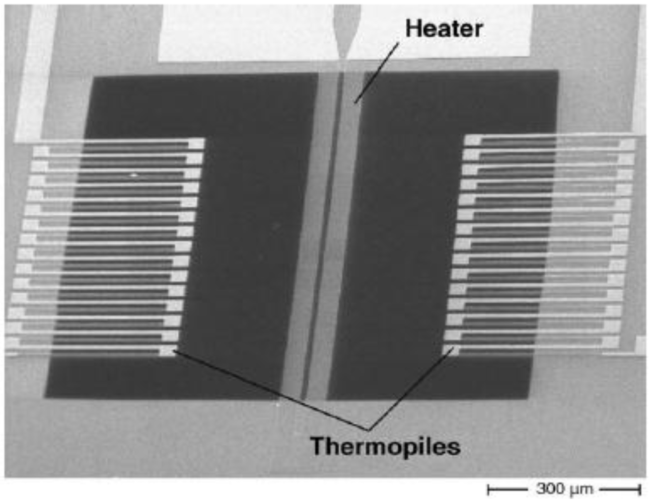
Figure 9.
SEM image of thermopiles placed around a heater in a calorimetric configuration for thermoelectric flow sensing [81].
Figure 9.
SEM image of thermopiles placed around a heater in a calorimetric configuration for thermoelectric flow sensing [81].

3.3. Thermoelectronic
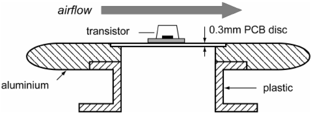
Makinwa and Huijsing used standard CMOS processing to create wind sensor with a central diode that measured the temperature of the chip. On-chip comparators are used to control temperature differences. In addition, thermopiles are also used for thermal flow sensing in a thermoelectric manner [88,89,90,91,92]. Makinwa and Huijsing also investigated the use of a bipolar transistor in hot-wire mode for airflow measurement (Figure 10). A decrease in packaging was achieved by the transistor’s self-heating; obviating the need for separate heaters [93].
Figure 10.
A transistor is soldered to a PCB and packaged for wind sensing [93].
Figure 10.
A transistor is soldered to a PCB and packaged for wind sensing [93].

| Material | Configuration | Gas/liquid | Resolution | Sensitivity | Range | Power Consumption | References |
|---|---|---|---|---|---|---|---|
| Polysilicon heater | Hot-wire | Air | 0.5 m/s | 0–30 m/s | Sun [35] | ||
| Polysilicon/Al Bipolar transistor | |||||||
| Ceramic | |||||||
| Al/Si PNP transistor | Calorimetric | Air | ±4% | 2–18 m/s | 0.4–1 W | Makinwa [89] | |
| Ceramic | Hot-wire | ||||||
| Bipolar transistor | Hot-wire | Air | 0–15 m/s | 50 mW | Makinwa [93] |
Thermoelectronic flow sensors were also realized in ceramic substrates (Table 5). Sun et al. fabricated thermopiles, polysilicon heaters, and a bipolar transistor and packaged them on a thin ceramic substrate. The sensor was exposed to flow through the underside of the ceramic substrate and heat transfer was aided by copper pillar bumps [35].
3.4. Frequency Analog
Conventional thermal flow sensors (operating in hot film mode) require calibration circuitry or external signal processing to maintain accuracy. The combination of a SAW transducer with a hot-wire sensing element provides the additional feedback information that eliminates the need for temperature calibration procedures [38].
The typical SAW transducer device utilizes the effects of temperature on resonance frequency (Table 6). However, an ultra-high temperature stable device made of ST-X quartz was fabricated that operates without the need for calibration. Resonance frequency shifts were negligible in response to temperature, but fluid flow induced a pressure gradient across a SAW transducer, resulting in an observable phase shift [94].
| Material | Configuration | Gas/liquid | Resolution | Sensitivity | Range | Power Consumption | References |
|---|---|---|---|---|---|---|---|
| Tungsten, Aluminum oxide | Hot-wire | Air | 3% | Kiełbasa [38] | |||
| LiNbO3, Au, Cr | Time-of-flight | Liquid, refractive index from 1.33–1.35 | 0.1 °C/10−5 change in refractive index unit | Renaudin [95] | |||
| Si, SiO2, Si3N4, Al | Time-of-flight | Air | Increases with temperature, geometry dependent | 0–20 m/s, geometry dependent | Iker [39] |
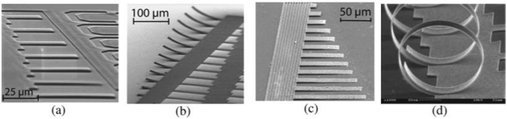
MEMS fabrication techniques have long been able to create three-dimensional microstructures, which enables geometries that may be fine-tuned (in terms of sensitivity and range) for thermal flow sensing (Figure 11). Self-assembling, interdigitated cantilever structures exhibit frequency changes in response to temperature, which is capacitively sensed [39].
Figure 11.
3D structures for frequency analog gas-flow sensing [39].
Figure 11.
3D structures for frequency analog gas-flow sensing [39].

Surface Plasmon Resonance (SPR) devices have also been integrated with SAW transducers (Figure 12). The intended purpose is to use the SAW action to induce fluid flow and utilize SPR for sensing a target analyte. However, it was reported that the SAW action creates localized heating, which may be observed through SPR [95].
Figure 12.
Integrated surface plasmon resonance (SPR) and surface acoustic waves (SAW) device [96].
Figure 12.
Integrated surface plasmon resonance (SPR) and surface acoustic waves (SAW) device [96].

3.5. Optical/SPR/Other
At the interface of specially selected materials, light couples to surface plasmons. This coupling is sensitive to changes in thickness, chemical species, and temperature, which manifests as a variation in reflectivity [95,96].
The resonance wavelength of an optical fiber Bragg grating will shift in response to temperature. Optical power heats up the grating, while fluid flow cools it. A pair of gratings were arranged to create a time-of-flight type sensor [97].
4. Conclusions
The current landscape of micromachined thermal flow sensors consists of the evolution of several established methodologies as well as the development and exploration of recent discoveries. Virtually any application can be addressed with the variety of materials, operation modes, transduction types (thermoresistive, thermoelectric, thermoelectronic, frequency analog), and configurations (hot-film, calorimetric, time-of-flight) that can be used to create flow sensors. The benefits of micromachined sensors are higher sensitivity to flow, ease of fabrication, and lack of moving parts as opposed to non-thermal flow sensing methods. Low cost micromachined thermal flow sensors will continue to mature and proliferate across many disciplines.
Acknowledgment
This work was funded in part by an NSF CAREER grant under Award Number EEC-0547544.
References
- Bolin, Y.; Zhiyin, G.; Shu, C.; Jingping, X.; Sheng, L. A micro channel integrated gas flow sensor for high sensitivity. In Proceedings of the 11th Intersociety Conference on Thermal and Thermomechanical Phenomena in Electronic Systems (ITHERM 2008), Orlando, FL, USA, 28-31 May, 2008.
- Cabuz, E.; Schwichtenberg, J.; DeMers, B.; Satren, E.; Padmanabhan, A.; Cabuz, C. MEMS-based flow controller for flow cytometry. In Proceedings of the Hilton Head 2002: Solid-State Sensor, Actuator and Microsystems Workshop, Hilton Head, SC, USA, 4-7 June, 2002.
- Sensirion Sensor Solutions; Sensirion—The Sensor Company: Staefa, Switzerland, 2012.
- Makinwa, K.A.A.; Huijsing, J.H. IEEE, A wind sensor with an integrated low-offset instrumentation amplifier. In Proceedings of the 8th IEEE International Conference on Electronics, Circuits and Systems, ICECS 2001, Malta, 2-5 September, 2001.
- Kaanta, B.C.; Chen, H.; Lambertus, G.; Steinecker, W.H.; Zhdaneev, O.; Zhang, X. High sensitivity micro-thermal conductivity detector for gas chromatography. In Proceedings of theIEEE 22nd International Conference on Micro Electro Mechanical Systems, Sorrento, Italy, 25-29 January, 2009.
- Lennart, L.; Mohamed, G.-E.-H. MEMS-based pressure and shear stress sensors for turbulent flows. Meas. Sci. Technol. 1999, 10, 665–686. [Google Scholar] [CrossRef]
- Po-Yau, J.; Chien-Hsiung, T.; Lung-Ming, F.; Che-Hsin, L. Microfluidic flow meter and viscometer utilizing flow-induced vibration on an optic fiber cantilever. In Proceedings of the 16th International Solid-State Sensors, Actuators and Microsystems Conference (TRANSDUCERS), Beijing, China, 5-9 June, 2011.
- Vanputte, A.F.; Middelho, S. Integrated silicon anemometer. Electron. Lett. 1974, 10, 425–426. [Google Scholar] [CrossRef]
- Nguyen, N.T. Micromachined flow sensors—A review. Flow Meas. Instrum. 1997, 8, 7–16. [Google Scholar] [CrossRef]
- Wang, Y.-H.; Chen, C.-P.; Chang, C.-M.; Lin, C.-P.; Lin, C.-H.; Fu, L.-M.; Lee, C.-Y. MEMS-based gas flow sensors. Microfluid. Nanofluidics 2009, 6, 333–346. [Google Scholar] [CrossRef]
- Meng, E.F.-C. MEMS Technology and Devices for a Microfluid Dosing System. Ph.D. Dissertation, California Institute of Technology, Pasadena, CA, USA, 2003; p. 150. [Google Scholar]
- King, L.V. On the convection of heat from small cylinders in a stream of fluid: Determination of the convection constants of small platinum wires with applications to hot-wire anemometry. Philos. Trans. R. Soc. Lond. Ser. A 1914, 214, 373–U44. [Google Scholar] [CrossRef]
- Madou, M.J. Fundamentals of Microfabrication: The Science of Miniaturization, 2nd ed; CRC Press: Boca Raton, FL, USA, 2002. [Google Scholar]
- Muller, R.S. Microsensors; IEEE Press: New York, NY, USA, 1991. [Google Scholar]
- Obermeier, E.; Kopystynski, P.; NieBl, R. Characteristics of polysilicon layers and their application in sensors. In IEEE Solid-State Sensors Workshop; IEEE Press: New York, NY, USA, 1986. [Google Scholar]
- Wolf, S.; Tauber, R.N. Silicon Processing for the VLSI Era, 2nd ed; Lattice Press: Sunset Beach, CA, USA, 2002; Volume 1. [Google Scholar]
- El-Kareh, B. Silicon Devices and Process Integration: Deep Submicron and Nano-scale Technologies; Springer: New York, NY, USA, 2009. [Google Scholar]
- Chuang, H.M.; Thei, K.B.; Tsai, S.F.; Liu, W.C. Temperature-dependent characteristics of polysilicon and diffused resistors. IEEE Trans. Electron. Devices 2003, 50, 1413–1415. [Google Scholar]
- Chuang, H.M.; Thei, K.B.; Tsai, S.F.; Lu, C.T.; Liao, X.D.; Lee, K.M.; Chen, H.R.; Liu, W.C. A comprehensive study of polysilicon resistors for CMOS ULSI applications. Superlattices Microstruct. 2003, 33, 193–208. [Google Scholar] [CrossRef]
- Meng, E. Biomedical Microsystems, 1st ed; CRC Press: Boca Raton, FL, USA, 2010. [Google Scholar]
- Dittmann, D.; Ahrens, R.; Rummler, Z.; Schlote-Holubek, K.; Schomburg, W.K. Low-Cost Flow Transducer Fabricated with the AMANDA-Process; Springer-Verlag: Berlin, Germany, 2001. [Google Scholar]
- Gardner, J.W. Microsensors: Principles and Applications, 1st ed; John Wiley & Sons: Hoboken, NJ, USA, 1994. [Google Scholar]
- Kreider, K.G.; DiMeo, F. Platinum/palladium thin-film thermocouples for temperature measurements on silicon wafers. Sens. Actuat. A 1998, 69, 46–52. [Google Scholar] [CrossRef]
- Mailly, F.; Giani, A.; Bonnot, R.; Temple-Boyer, P.; Pascal-Delannoy, F.; Foucaran, A.; Boyer, A. Anemometer with hot platinum thin film. Sens. Actuat. A 2001, 94, 32–38. [Google Scholar] [CrossRef]
- van Honschoten, J.; van Baar, J.; de Bree, H.E.; Lammerink, T.; Krijnen, G.; Elwenspoek, M. Application of a microflown as a low-cost level sensor. J. Micromech. Microeng. 2000, 10, 250–253. [Google Scholar] [CrossRef]
- Kuo, J.T.W.; Chang, L.-Y.; Li, P.-Y.; Hoang, T.; Meng, E. A microfluidic platform with integrated flow sensing for focal chemical stimulation of cells and tissue. Sens. Actuat. B 2011, 152, 267–276. [Google Scholar] [CrossRef]
- van Kuijk, J.; Lammerink, T.; de Bree, H.E.; Elwenspoek, M.; Fluitman, J. Multi-parameter detection in fluid flows. Sens. Actuat. A 1995, 47, 369–372. [Google Scholar] [CrossRef]
- Ito, Y.; Higuchi, T.; Takahashi, K. Submicroscale flow sensor employing suspended hot film with carbon nanotube fins. J. Therm. Sci. Technol. 2010, 5, 51–60. [Google Scholar] [CrossRef]
- Kaltsas, G.; Nassiopoulou, A.G. Novel C-MOS compatible monolithic silicon gas flow sensor with porous silicon thermal isolation. Sens. Actuat. A 1999, 76, 133–138. [Google Scholar] [CrossRef]
- Buchner, R.; Froehner, K.; Sosna, C.; Benecke, W.; Lang, W. Toward flexible thermoelectric flow sensors: A new technological approach. J. Microelectromechanical Syst. 2008, 17, 1114–1119. [Google Scholar] [CrossRef]
- Akin, T. CMOS-based thermal sensors. In CMOS-MEMS; Brand, O., Fedder, G.K., Eds.; Wiley-VCH: Hoboken, NJ, USA, 2005; pp. 483–487. [Google Scholar]
- Sze, S.M. Semiconductor Sensors; Wiley: New York, NY, USA, 1994. [Google Scholar]
- Volklein, F. Review of the thermoelectric efficiency of bulk and thin-film materials. Sens. Mater. 1996, 8, 389–408. [Google Scholar]
- Millman, J.; Halkias, C.C. Integrated Electronics: Analog and Digital Circuits and Systems; McGraw-Hill: New York, NY, USA, 1972. [Google Scholar]
- Sun, J.-B.; Qin, M.; Huang, Q.-A. Flip-chip packaging for a two-dimensional thermal flow sensor using a copper pillar bump technology. IEEE Sens. J. 2007, 7, 990–995. [Google Scholar] [CrossRef]
- Joshi, S.G. Flow sensors based on surface acoustic waves. Sens. Actuat. A 1994, 44, 191–197. [Google Scholar] [CrossRef]
- Langdon, R.M. Resonator sensors—A review. J. Phys. E 1985, 18, 103–115. [Google Scholar] [CrossRef]
- Kielbasa, J. Measurement of gas flow velocity: Anemometer with a vibrating hot wire. Rev. Sci. Instrum. 2010, 81, 015101:1–015101:4. [Google Scholar]
- Iker, F.; Andre, N.; Pardoen, T.; Raskin, J.P. Three-dimensional self-assembled sensors in thin-film SOI technology. J. Microelectromechanical Syst. 2006, 15, 1687–1697. [Google Scholar] [CrossRef]
- Sabaté, N.; Santander, J.; Fonseca, L.; Gràcia, I.; Cané, C. Multi-range silicon micromachined flow sensor. Sens. Actuat. A 2004, 110, 282–288. [Google Scholar] [CrossRef]
- Adamec, R.J.; Thiel, D.V. Self heated thermo-resistive element hot wire anemometer. IEEE Sens. J. 2010, 10, 847–848. [Google Scholar] [CrossRef]
- Kaanta, B.C.; Chen, H.; Zhang, X. Novel device for calibration-free flow rate measurements in micro gas chromatographic systems. J. Micromech. Microeng. 2010. [Google Scholar] [CrossRef]
- Nguyen, N.T.; Dötzel, W. Asymmetrical locations of heaters and sensors relative to each other using heater arrays: A novel method for designing multi-range electrocaloric mass-flow sensors. Sens. Actuat. A 1997, 62, 506–512. [Google Scholar] [CrossRef]
- Soundararajan, G.; Rouhanizadeh, M.; Yu, H.Y.; De Maio, L.; Kim, E.S.; Hsiai, T.K. MEMS shear stress sensors for microcirculation. Sens. Actuat. A 2005, 118, 25–32. [Google Scholar]
- Wu, S.; Lin, Q.; Yuen, Y.; Tai, Y.-C. MEMS flow sensors for nano-fluidic applications. Sens. Actuat. A 2001, 89, 152–158. [Google Scholar] [CrossRef]
- Bailey, S.C.C.; Kunkel, G.J.; Hultmark, M.; Vallikivi, M.; Hill, J.P.; Meyer, K.A.; Tsay, C.; Arnold, C.B.; Smits, A.J. Turbulence measurements using a nanoscale thermal anemometry probe. J. Fluid Mech. 2010, 663, 160–179. [Google Scholar] [CrossRef]
- Meng, E.; Li, P.-Y.; Tai, Y.-C. A biocompatible Parylene thermal flow sensing array. Sens. Actuat. A 2008, 144, 18–28. [Google Scholar] [CrossRef]
- Chang, L.-Y.; Li, P.-Y.; Zhao, L.; Hoang, T.; Meng, E. Integrated flow sensing for focal biochemical stimulation. In Proceedings of the 3rd IEEE International Conference on Nano/Micro Engineered and Molecular Systems, Sanya Hainan Island, China, 6-9 January 2008.
- Berthet, H.; Jundt, J.; Durivault, J.; Mercier, B.; Angelescu, D. Time-of-flight thermal flowrate sensor for lab-on-chip applications. Lab Chip 2011, 11, 215–223. [Google Scholar] [CrossRef]
- Fürjes, P.; Légrádi, G.; Dücső, C.; Aszódi, A.; Bársony, I. Thermal characterisation of a direction dependent flow sensor. Sens. Actuat. A 2004, 115, 417–423. [Google Scholar] [CrossRef]
- Hung, S.-T.; Wong, S.-C.; Fang, W. The development and application of microthermal sensors with a mesh-membrane supporting structure. Sens. Actuat. A 2000, 84, 70–75. [Google Scholar] [CrossRef]
- Dijkstra, M.; de Boer, M.J.; Berenschot, J.W.; Lammerink, T.S.J.; Wiegerink, R.J.; Elwenspoek, M. Miniaturized thermal flow sensor with planar-integrated sensor structures on semicircular surface channels. Sens. Actuat. A 2008, 143, 1–6. [Google Scholar] [CrossRef]
- Hsiai, T.K.; Cho, S.K.; Wong, P.K.; Ing, M.H.; Salazar, A.; Hama, S.; Navab, M.; Demer, L.L.; Chih-Ming, H. Micro sensors: Linking real-time oscillatory shear stress with vascular inflammatory responses. Ann. Biomed. Eng. 2004, 32, 189–201. [Google Scholar] [CrossRef]
- Liu, C.; Huang, J.-B.; Zhu, Z.; Jiang, F.; Tung, S.; Tai, Y.-C.; Ho, C.-M. A micromachined flow shear-stress sensor based on thermal transfer principles. J. Microelectromechanical Syst. 1999, 8, 90–99. [Google Scholar] [CrossRef]
- Kaltsas, G.; Petropoulos, A.; Tsougeni, K.; Pagonis, D.N.; Speliotis, T.; Gogolides, E.; Nassiopoulou, A.G. A novel microfabrication technology on organic substrates—Application to a thermal flow sensor. J. Phys. Conf. Ser. 2007. [Google Scholar] [CrossRef]
- Vilares, R.; Hunter, C.; Ugarte, I.; Aranburu, I.; Berganzo, J.; Elizalde, J.; Fernandez, L.J. Fabrication and testing of a SU-8 thermal flow sensor. Sens. Actuat. B 2010, 147, 411–417. [Google Scholar] [CrossRef]
- Ma, R.-H.; Wang, D.-A.; Hsueh, T.-H.; Lee, C.-Y. A MEMS-based flow rate and flow direction sensing platform with integrated temperature compensation scheme. Sensors 2009, 9, 5460–5476. [Google Scholar] [CrossRef]
- Shen, G.-P.; Qin, M.; Huang, Q.-A.; Zhang, H.; Wu, J. A FCOB packaged thermal wind sensor with compensation. Microsyst. Technol. 2010, 16, 511–518. [Google Scholar] [CrossRef]
- Domínguez, M.; Jiménez, V.; Ricart, J.; Kowalski, L.; Torres, J.; Navarro, S.; Romeral, J.; Castañer, L. A hot film anemometer for the Martian atmosphere. Planet. Space Sci. 2008, 56, 1169–1179. [Google Scholar] [CrossRef]
- Chen, J.; Fan, Z.F.; Zou, J.; Engel, J.; Liu, C. Two-dimensional micromachined flow sensor array for fluid mechanics studies. J. Aerosp. Eng. 2003, 16, 85–97. [Google Scholar] [CrossRef]
- Tan, Z.; Shikida, M.; Hirota, M.; Xing, Y.; Sato, K.; Iwasaki, T.; Iriye, Y. Characteristics of on-wall in-tube flexible thermal flow sensor under radially asymmetric flow condition. Sens. Actuat. A 2007, 138, 87–96. [Google Scholar] [CrossRef]
- Tan, Z.Y.; Shikida, M.; Hirota, M.; Sato, K.; Iwasaki, T.; Iriye, Y. Experimental and theoretical study of an on-wall in-tube flexible thermal sensor. J. Micromech. Microeng. 2007, 17, 679–686. [Google Scholar] [CrossRef]
- Liu, P.; Zhu, R.; Que, R. A flexible flow sensor system and its characteristics for fluid mechanics measurements. Sensors 2009, 9, 9533–9543. [Google Scholar] [CrossRef]
- Ahrens, R.; Schlote-Holubek, K. A micro flow sensor from a polymer for gases and liquids. J. Micromech. Microeng. 2009. [Google Scholar] [CrossRef]
- Ahrens, R.; Festa, M. Polymer-based micro flow sensor for dynamical flow measurements in hydraulic systems. J. Micromech. Microeng. 2010. [Google Scholar] [CrossRef]
- Li, C.Y.; Wu, P.M.; Han, J.; Ahn, C.H. A flexible polymer tube lab-chip integrated with microsensors for smart microcatheter. Biomed. Microdevices 2008, 10, 671–679. [Google Scholar] [CrossRef]
- Li, C.; Wu, P.-M.; Hartings, J.A.; Wu, Z.; Ahn, C.H.; Narayan, R.K. Cerebral blood flow sensor with in situ temperature and thermal conductivity compensation. In Proceedigns of the 25th International Conference on Micro Electro Mechanical Systems, Paris, France, 29 January-2 February 2012; pp. 1021–1024.
- Li, C.Y.; Wu, P.M.; Hartings, J.A.; Wu, Z.Z.; Ahn, C.H.; LeDoux, D.; Shutter, L.A.; Narayan, R.K. Smart catheter flow sensor for real-time continuous regional cerebral blood flow monitoring. Appl. Phys. Lett. 2011, 99, 233705–1. [Google Scholar]
- Yu, F.; Ai, L.S.; Dai, W.D.; Rozengurt, N.; Yu, H.Y.; Hsiai, T.K. MEMS thermal sensors to detect changes in heat transfer in the pre-atherosclerotic regions of fat-fed New Zealand white rabbits. Ann. Biomed. Eng. 2011, 39, 1736–1744. [Google Scholar] [CrossRef]
- Yu, H.; Ai, L.; Rouhanizadeh, M.; Patel, D.; Kim, E.S.; Hsiai, T.K. Flexible polymer sensors for in vivo intravascular shear stress analysis. J. Microelectromechanical Syst. 2008, 17, 1178–1186. [Google Scholar] [CrossRef]
- Yu, H.; Ai, L.; Rouhanizadeh, M.; Kloner, R.A.; Kim., E.S.; Hsiai, T.K. Flexible shear stress sensors for intravascular testing. In Proceedings of the Solid-State Sensors, Actuators Workshop, Hilton Head, SC, USA, 1-5 June 2008; pp. 142–145.
- Yu, H.Y.; Ai, L.S.; Rouhanizadeh, M.; Hamilton, R.; Hwang, J.; Meng, E.; Kim, E.S.; Hsiai, T.K. Polymer-based cardiovascular shear stress sensors. In Proceedings of the 2nd Frontiers in Biomedical Devices Conference (BioMed2007), Irvine, CA, USA, 7-8 June 2007.
- Ai, L.S.; Yu, H.Y.; Dai, W.D.; Hale, S.L.; Kloner, R.A.; Hsiai, T.K. Real-time intravascular shear stress in the rabbit abdominal aorta. IEEE Trans. Biomed. Eng. 2009, 56, 1755–1764. [Google Scholar] [CrossRef]
- Ai, L.S.; Yu, H.Y.; Rouhanizadeh, M.; Takabe, W.; Meng, E.; Kim, E.S.; Hsiai, T. Polymer-based sensors for dynamic intravascular shear stress analysis. In Proceedings of the 3rd Frontiers in Biomedical Devices Conferences (BioMed2008), Irvine, CA, USA, 18-20 June 2008.
- Ai, L.S.; Zhang, L.Q.; Dai, W.D.; Hu, C.H.; Shung, K.K.; Hsiai, T.K. Real-time assessment of flow reversal in an eccentric arterial stenotic model. J. Biomech. 2010, 43, 2678–2683. [Google Scholar]
- Ernst, H.; Jachimowicz, A.; Urban, G.A. High resolution flow characterization in bio-MEMS. Sens. Actuat. A 2002, 100, 54–62. [Google Scholar] [CrossRef]
- Cubukcu, A.S.; Zernickel, E.; Buerklin, U.; Urban, G.A. A 2D thermal flow sensor with sub-mW power consumption. Sens. Actuat. A 2010, 163, 449–456. [Google Scholar] [CrossRef]
- Kaltsas, G.; Nassiopoulos, A.A.; Nassiopoulou, A.G. Characterization of a silicon thermal gas-flow sensor with porous silicon thermal isolation. IEEESens. J. 2002, 2, 463–475. [Google Scholar]
- Kaltsas, G.; Katsikogiannis, P.; Asimakopoulos, P.; Nassiopoulou, A.G. A smart flow measurement system for flow evaluation with multiple signals in different operation modes. Meas. Sci. Technol. 2007. [Google Scholar] [CrossRef]
- Stamatopoulos, C.; Petropoulos, A.; Mathioulakis, D.S.; Kaltsas, G. Study of an integrated thermal sensor in different operational modes, under laminar, transitional and turbulent flow regimes. Exp. Therm. Fluid Sci. 2008, 32, 1687–1693. [Google Scholar] [CrossRef]
- Buchner, R.; Sosna, C.; Maiwald, M.; Benecke, W.; Lang, W. A high-temperature thermopile fabrication process for thermal flow sensors. Sens. Actuat. A 2006, 130-131, 262–266. [Google Scholar] [CrossRef]
- Laconte, J.; Dupont, C.; Flandre, D.; Raskin, J.P. SOI CMOS compatible low-power microheater optimization for the fabrication of smart gas sensors. IEEE Sens. J. 2004, 4, 670–680. [Google Scholar] [CrossRef]
- Wiegerink, R.J.; Lammerink, T.S.J.; Dijkstra, M.; Haneveld, J. Thermal and Coriolis type micro flow sensors based on surface channel technology. Procedia Chem. 2009, 1, 1455–1458. [Google Scholar] [CrossRef]
- Bruschi, P.; Diligenti, A.; Navarrini, D.; Piotto, M. A double heater integrated gas flow sensor with thermal feedback. Sens. Actuat. A 2005, 123-124, 210–215. [Google Scholar] [CrossRef]
- Bruschi, P.; Dei, M.; Piotto, M. A low-power 2-D wind sensor based on integrated flow meters. IEEE Sens. J. 2009, 9, 1688–1696. [Google Scholar] [CrossRef]
- Bruschi, P.; Nurra, V.; Piotto, M. A compact package for integrated silicon thermal gas flow meters. Microsyst. Technol. Micro Nanosyst. Inf. Storage Process. Syst. 2008, 14, 943–949. [Google Scholar]
- Sturm, H.; Brauns, E.; Froehner, K.; Lang, W.; Buchner, R. Thermoelectric flow sensors on flexible substrates and their integration process. In 2010 IEEE Sensors; IEEE Press: New York, NY, USA, 2010; pp. 575–579. [Google Scholar]
- Makinwa, K.A.A.; Huijsing, J.H. A smart wind sensor using thermal sigma-delta modulation techniques. Sens. Actuat. A 2002, 97-98, 15–20. [Google Scholar] [CrossRef]
- Makinwa, K.A.A.; Huijsing, J.H. A wind-sensor interface using thermal sigma delta modulation techniques. Sens. Actuat. A 2001, 92, 280–285. [Google Scholar] [CrossRef]
- Makinwa, K.A.A.; Huijsing, J.H. Constant power operation of a two-dimensional flow sensor. IEEE Trans. Instrum. Meas. 2002, 51, 840–844. [Google Scholar] [CrossRef]
- Makinwa, K.A.A.; Huijsing, J.H. A smart wind sensor using thermal sigma-delta modulation techniques. Sens. Actuat. A 97-9, 2002, 15–20. [Google Scholar]
- Matova, S.P.; Makinwa, K.A.A.; Huijsing, J.H. Compensation of packaging asymmetry in a 2-D wind sensor. IEEE Sens. J. 2003, 3, 761–765. [Google Scholar] [CrossRef]
- Makinwa, K.A.A.; Huijsing, J.H. A 2nd order thermal sigma-delta modulator for flow sensing. In 2005 IEEE Sensors; IEEE Press: New York, NY, USA, 2005; Volume 1 and 2, pp. 549–552. [Google Scholar]
- Wang, Y.Z.; Li, Z.; Qin, L.F.; Chyu, M.K.; Wang, Q.M. Surface acoustic wave flow sensor. In Proceedings of the IEEE International Frequency Control Symposium on 2011 Joint Conference of the IEEE International Frequency Control Symposium/European Frequency and Time Forum, San Francisco, CA, USA, 2-5 May 2011; pp. 428–431.
- Renaudin, A.; Chabot, V.; Grondin, E.; Aimez, V.; Charette, P.G. Integrated active mixing and biosensing using surface acoustic waves (SAW) and surface plasmon resonance (SPR) on a common substrate. Lab Chip 2010, 10, 111–115. [Google Scholar] [CrossRef]
- Friedt, J.M.; Francis, L.; Reekmans, G.; De Palma, R.; Campitelli, A.; Sleytr, U.B. Simultaneous surface acoustic wave and surface plasmon resonance measurements: Electrodeposition and biological interactions monitoring. J. Appl. Phys. 2004, 95, 1677–1680. [Google Scholar]
- Jewart, C.; McMillen, B.; Cho, S.K.; Chen, K.P. X-probe flow sensor using self-powered active fiber Bragg gratings. Sens. Actuat. A 2006, 127, 63–68. [Google Scholar] [CrossRef]
© 2012 by the authors; licensee MDPI, Basel, Switzerland. This article is an open-access article distributed under the terms and conditions of the Creative Commons Attribution license (http://creativecommons.org/licenses/by/3.0/).
Share and Cite
MDPI and ACS Style
Kuo, J.T.W.; Yu, L.; Meng, E. Micromachined Thermal Flow Sensors—A Review. Micromachines 2012, 3, 550-573. https://doi.org/10.3390/mi3030550
AMA Style
Kuo JTW, Yu L, Meng E. Micromachined Thermal Flow Sensors—A Review. Micromachines. 2012; 3(3):550-573. https://doi.org/10.3390/mi3030550
Chicago/Turabian StyleKuo, Jonathan T. W., Lawrence Yu, and Ellis Meng. 2012. "Micromachined Thermal Flow Sensors—A Review" Micromachines 3, no. 3: 550-573. https://doi.org/10.3390/mi3030550