A Study on Millimetre-Wave Tunable Bandpass Filter Based on Polymer Cap Deflection

Abstract
:1. Introduction
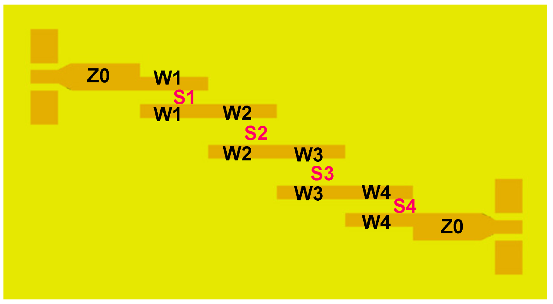
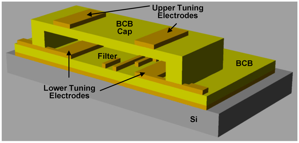
2. Concept and Design


| j | (Zoe)j,j+1 | (Zoo)j,j+1 | j | Wj (µm) | Sj (µm) | |
|---|---|---|---|---|---|---|
| 0 | 67.6 | 40 | 1 and 4 | 70 | 10 | |
| 1 | 53.9 | 46.7 | 2 and 3 | 80 | 60 | |
| (a) | (b) | |||||

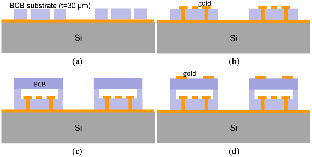
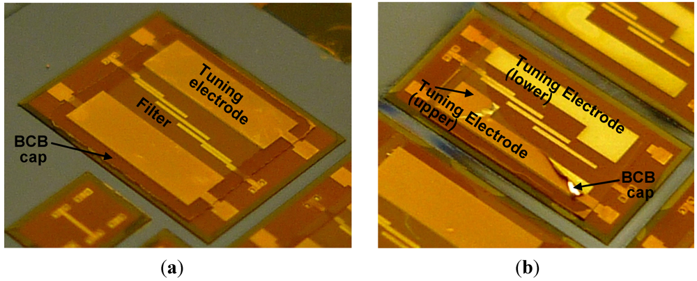
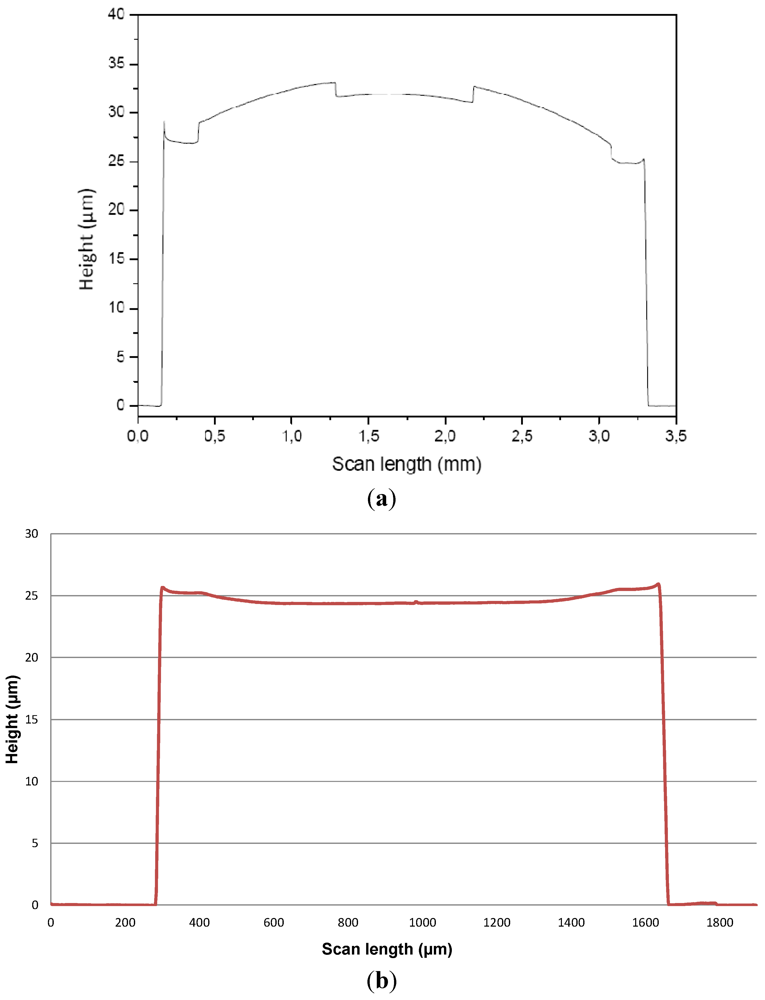
3. Fabrication


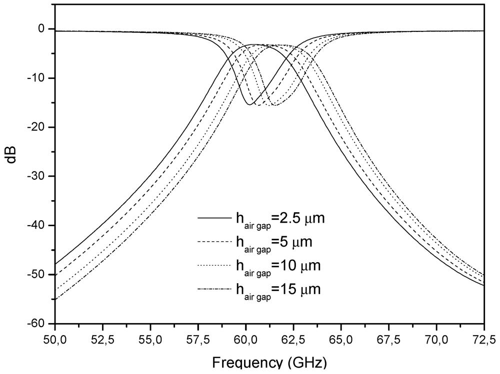
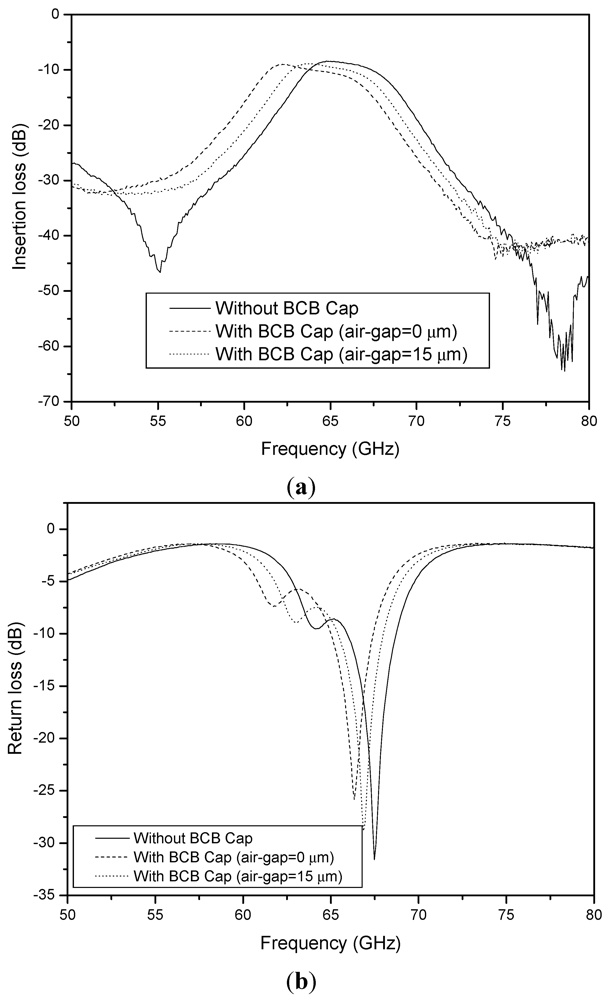
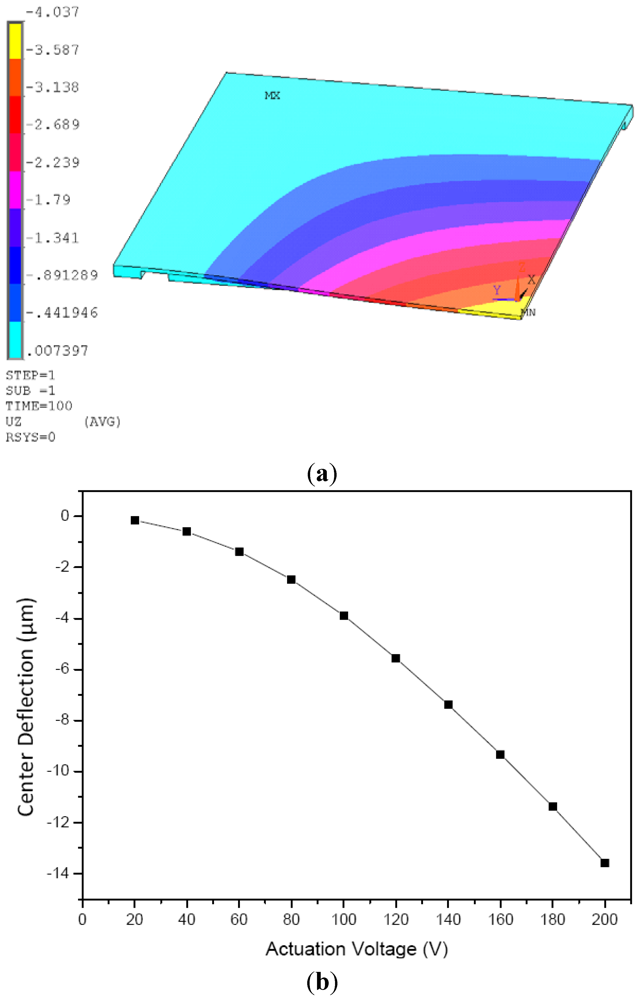
4. Characterizations and Discussions

5. Conclusions
Acknowledgments
References
- Baker, N.S.; Rebeiz, G.M. Distributed MEMS True-Time Delay Phase Shifters and Wide-Band Switches. IEEE Trans. Microwave Theory 1999, 46, 299–302. [Google Scholar]
- Weller, T.M.; Katehi, L.P.B.; Rebeiz, G.M. High Performance Microshield Line Components. IEEE Trans. Microwave Theory 1995, 43, 534–543. [Google Scholar] [CrossRef]
- Kudrle, T.D.; Neves, H.P.; Rodger, D.C.; MacDonald, N.C. A Microactuated Millimeter Wave Phase Shifter. In Proceedings of Solid-State Sensor and Actuator Workshop, Digest Tech, Sendai, Japan, 7-10 June 1999; pp. 1276–1279.
- Seok, S.; Rolland, N.; Rolland, P.A. Packaging Methodology for RF Devices Using a BCB Membrane Transfer Technique. J. Micromech. Microeng. 2006, 2384–2388. [Google Scholar]
- Hajela, S.; Gong, X.; Chappell, J.W. Widely Tunable High-Q Evanescent-Mode Resonators Using Flexible Polymer Substrates. In Proceedings of 2005 IEEE MTT-S International Microwave Symposium Digest, Long beach, CA, USA, 12-17 June 2005; pp. 2139–2142.
- Nicolson, D. A High Performance Hexagonal Ferrite Tunable Bandpass Filter for the 40-60 GHz Region. In Proceedings of 1985 IEEE MTT-S International Microwave Symposium Digest, St. Louis, MO, USA, 4-6 June 1985; pp. 229–232.
- Kim, J.; Seok, S.; Rolland, N.; Rolland, P.A. A Novel Wafer Level Bonding/Debonding Technique Using an Anti-adhesion Layer for Polymer-based 0-level Packaging of RF device. In Proceedings of The 60th Electronic Components and Technology Conference (ECTC 2010), Las Vegas, NV, USA, 1-4 June 2010; pp. 323–328.
- Hong, J.S.; Lancaster, M.J. Microstrip Filters for RF/Microwave Applications 2001; John Wiley & Sons, Inc.: New York, NY, USA.
- Seok, S.; Rolland, N.; Rolland, P.A. A Theoretical and Experimental Study of BCB Thin-Film Cap Zero-Level Package Based on FEM Simulations. J. Micromech. Microeng. 2010. [Google Scholar] [CrossRef]
© 2012 by the authors; licensee MDPI, Basel, Switzerland. This article is an open-access article distributed under the terms and conditions of the Creative Commons Attribution license (http://creativecommons.org/licenses/by/3.0/).
Share and Cite
Seok, S.; Kim, J.; Rolland, N.; Rolland, P.-A. A Study on Millimetre-Wave Tunable Bandpass Filter Based on Polymer Cap Deflection. Micromachines 2012, 3, 28-35. https://doi.org/10.3390/mi3010028
Seok S, Kim J, Rolland N, Rolland P-A. A Study on Millimetre-Wave Tunable Bandpass Filter Based on Polymer Cap Deflection. Micromachines. 2012; 3(1):28-35. https://doi.org/10.3390/mi3010028
Chicago/Turabian StyleSeok, Seonho, Janggil Kim, Nathalie Rolland, and Paul-Alain Rolland. 2012. "A Study on Millimetre-Wave Tunable Bandpass Filter Based on Polymer Cap Deflection" Micromachines 3, no. 1: 28-35. https://doi.org/10.3390/mi3010028