
Wavelet-Based Local Contrast Enhancement for Satellite, Aerial and Close Range Images

Department of Geoinformation, Photogrammetry and Environmental Remote Sensing, AGH University of Science and Technology, 30-059 Krakow, Poland
Remote Sens. 2017, 9(1), 25; https://doi.org/10.3390/rs9010025
Submission received: 4 November 2016
/
Revised: 22 December 2016
/
Accepted: 28 December 2016
/
Published: 1 January 2017
Abstract
:The methods used for image contrast enhancement in the wavelet domain have been previously documented. The essence of these methods lies in the manipulation of the image during the reconstruction process, by changing the relationship between the components that require transformation. This paper proposes a new variant based on using undecimated wavelet transform and adapting the Gaussian function for scaling the coefficients of detail wavelet components, so that the role of low coefficients in the reconstructed image is greater. The enhanced image is then created by combining the new components. Applying the Haar wavelet minimises the effects of the relationship disturbance between components, and creates a small buffer around the edge. The proposed method was tested using six images at different scales, collected with handheld photo cameras, and aerial and satellite optical sensors. The results of the tests indicate that the method can achieve comparable, or even better enhancement effects for weak edges, than the well-known unsharp masking and Retinex methods. The proposed method can be applied in order to improve the visual interpretation of remote sensing images taken by various sensors at different scales.
1. Introduction
The interpretation of image content is performed in a visual and, more and more, in an automatic manner. The radiometric quality of the images in both cases is critical for the resulting analyses. Nowadays many optical sensors are used for acquiring images. Typically, imaging sensors for remote sensing are satellite systems based on linear detector array and digital (formerly analogue) large-format aerial cameras. For capturing cultural heritage or industrial objects, various digital photo cameras are being used, much like those for taking photos from unmanned aerial vehicles (UAV). The diversity of image types is the reason for searching for universal image-enhancement methods.
Image enhancement entails emphasising the essential characteristics and minimising the less important characteristics according to the requirements and purpose of that particular image. One of the most significant ways of enhancing an image is by increasing the local contrast for better representation of the image details [1,2,3].
When an image is analysed, its elements are assigned a meaning in the real world. One looks at an image at various scales, firstly by looking at the image as a whole, and then gradually focusing on various details. Initially, one perceives shapes formed by lines that contrast with their surroundings, and large areas of relatively uniform colour or texture [4]. The ability to perceive edges depends on the line contrast relative to its local background [5]. Another property of the human visual system involves the variable response to luminance, depending on the spatial frequency—the eye reacts as a mid-pass filter [6]. For these reasons, image edges are crucial in the process of analysing image content.
An edge in the image is a spot where there is significant local change in luminance. The condition of the edge visibility depends on sufficient change in luminance, relative to its immediate surroundings, that is, the local background (the threshold value is usually assumed to be 2%) [5]. The aim of the research presented in this paper is to develop a method where the edges are enhanced with low local contrast and the areas with high contrast are left unchanged. This method will be called WLCE (Wavelet-based Local Contrast Enhancement).
The wavelet transform is gaining new fields of application, one of which is in image processing. Wavelets are commonly used for lossy compression, removing noise and fusing images of different geometric resolutions together [1,7,8,9]. Research is being conducted on wavelet edge enhancement [7,10,11]. The discrete wavelet transform (DWT) is used in most cases [1,12,13]. In recent years, there has been a tendency to use more advanced wavelet algorithms. In this paper, the undecimated discrete wavelet transform (UDWT) is used for edge enhancement.
The structure of this paper is as follows. First, in Section 1.1, the characteristics of the UDWT are discussed in the context of the wavelet transform since it is the mathematical base of the proposed image-enhancement method. In Section 1.2, the selected image-enhancement methods are briefly presented. Then, in Section 2, the proposed enhancement method and materials are presented. The section thereafter demonstrates the results of the experiments conducted on six test images with different characteristics. The results of the wavelet enhancement are compared against the unsharp masking and Retinex methods in the visual and quantitative manner. Then, Section 4 discusses the results. The paper concludes with a summary containing an indication of the strengths and weaknesses of the proposed enhancement method and recommended areas of future research.
1.1. The Undecimated Discrete Wavelet Transform (UDWT) versus other Wavelet Transforms
The wavelet transform is the transformation of a signal from the time domain to the frequency domain, wherein the information about the frequency changes in relation to a known time. The name of a wavelet was first used by Grossmann and Morlet [14], but the first algorithm with wavelet transform characteristics was published by Haar in 1910. From a theoretical point of view, the continuous wavelet transform (CWT) is of key importance [15,16]. The CWT is a sum of scalar products of the signal f(t) with scaled and translated versions of the wavelet function ψ(t). There are many types of wavelets and the largest wavelet group is the orthogonal compactly supported wavelet. Among the orthogonal wavelets, the Haar wavelet is the simplest, shortest and oldest [15].
The CWT is inherently redundant and computationally complex and creates a very large data set. Therefore, the DWT is more frequently used in practice. A significant contribution to the development of the DWT was given by Stephane Mallat, who developed a highly efficient algorithm [17]. The decomposition of the signal occurs by splicing the signal with upper-pass and lower-pass filters, representing the basic wavelet and the scaling wavelet, and the results are the wavelet (detail) component and the smooth (coarse) component. The decomposition can be continued on subsequent resolution levels. Dyadic sub-sampling occurs between splicing sequences. Both the wavelet decomposition and the signal reconstruction can be realised using matrix transformations which consist of the multiplication of signal by the filtering matrix constructed out of filter coefficients and sequences of zeroes [18].
The DWT has two significant drawbacks: the length of the signal must be a natural power of the number 2, and the result of the transformation is dependent on the signal shift. However, these difficulties disappear if one abandons the dyadic sub-sampling and uses the oversampling in the filter matrix instead in accordance with the so-called “algorithme a trous” [19]. Apart from the UDWT, this redundant transformation variant has several names: non-decimated DWT, maximal overlap DWT, shift invariant DWT, translation invariant DWT, redundant DWT (RDWT), and stationary wavelet transform (SWT) [18,20,21].
In the UDWT, the signal reconstruction is a process that is inverse to decomposition, which uses the inverse of the filtering matrix, as in the DWT. The UDWT can be implemented in the MRA (Multi-Resolution Analysis) variant [18,20]. In this case, the reconstruction of a 2D signal occurs by summing up the components, as represented by the formula:
where x is the 2D signal (e.g., a digital image represented by the matrix with the size of M∙N), sJ is the smooth component from the last decomposition level J and dj,k denotes a series of three detail components k = {1, 2, 3} (vertical, horizontal, and diagonal) for the decomposition level j = {1, 2, …, J}.
The transformation components obtained from the UDWT-MRA variant vary from those in the classical UDWT algorithm. From both the undecimated variants, only the classical UDWT preserves the energy of the signal during its decomposition, like the DWT. For all cases of wavelet transformation, the distributions of the detail coefficients are strongly uplifted at zero and are modelled by the generalised Gaussian distribution (GGD) [17,22]. A more detailed description of UDWT decomposition and reconstruction can be found in [23].
1.2. Selected Image-Enhancement Methods
There are many image-enhancement methods and the most general divisions distinguish between two groups: those operating in the spatial domain and those operating in the frequency domain [1]. Those operating in the spatial domain group are numerous and most of them probably use histogram-based techniques, which are more suitable for global rather than local contrast enhancement. Good local contrast enhancement results are achieved by the unsharp masking (UM) and Retinex methods, which also operate in the spatial domain. The classic UM algorithm first smooths the image with the Gaussian mask, and the resulting blurred version is subtracted from the source image [5]. The classic Retinex algorithm also subtracts the blurred version from the source image. However, instead of pixel values (Digital Number—DN), their logarithms (in DN) are subtracted. Consequently, there is a resulting logarithm of the quotient of the source image and the blurred image. For this reason, the Retinex method enhances edges more strongly than the UM. Newer Retinex algorithms carry out edge enhancement at several scales, i.e., Multiscale Retinex (MSR) [24,25] and have been used for uneven illumination correction [26]. Both the UM and MSR methods have been implemented in a number of image processing tools and are commonly used, hence they were selected as the reference methods in this study.
The frequency domain was first used for image enhancement by the Fourier transform [1,5]. The transform gives the synthetic frequency spectrum for the entire image and cannot specify the locations where changes in frequencies occur. Therefore, it is especially effective in the removal of systematic noise. A method which uses the Fourier transform for illumination and contrast balancing of satellite images is presented in [27]. The wavelet transform does not have this shortcoming, and is able to locate where particular frequencies occur. Thus its use for image enhancement is wider and new possibilities of application are still being discovered. Additionally, the Gabor transform is also widely used, which combines the characteristics of the Fourier and wavelet transforms. The Gabor transform is employed in applications that incorporate fingerprint analysis and facial recognition [28].
The wavelet transform is considered one of the best methods for the reduction of random noise. The principles used in wavelet noise reduction have resolved certain issues in the present study’s image enhancement concept. For this reason, it is advisable to outline wavelet noise reduction. The method can be divided into three main stages: (1) the DWT signal transform; (2) cutting off the noise from the signal in the wavelet space; and (3) the reconstruction of the signal [29]. A characteristic feature of noise is its concentration on the first wavelet decomposition level and its fading in subsequent levels. The simplest method to cut off noise (referred to as the hard method) involves zeroing the wavelet coefficients, whose absolute value is less than or equal to the predetermined threshold value (the coefficients of a greater value remain unchanged). The basic problem is in finding the threshold for cutting off the noise from the signal. The SureShrink method uses the well-known Stein’s Unbiased Risk Estimator (SURE) for this purpose [30]. Further work on the improvement of wavelet image noise reduction continue to be conducted [29,31,32].
The original method of image enhancement, by combining operations in the spatial domain and the frequency domain, was proposed in [33]. It involves scaling the DWT coefficients to achieve an image with optimal mean and standard deviations of luminance. The scaling ratio is calculated in the wavelet space, by analysing the contrasts in subsequent decomposition levels. Another way to perform operations on the histogram using the wavelet transform is shown in [34]. It demonstrates that it is possible to achieve favourable histogram equalisation by analysing the wavelet coefficients of the adjacent pixels. A method which combines contrast limited adaptive histogram equalisation (CLAHE) with DWT is presented in [35]. The simultaneous use of the DWT and UDWT for image resolution enhancement is proposed in [11].
Enhancement of image contrast by scaling the wavelet coefficients is becoming more and more popular. Various solutions indicate different image parameters for optimisation [36,37,38]. Most of the solutions increase the defined contrast, using a particular statistical measure. The term “multiscale local contrast” is very often applied, based on the definition given by Peli [39]: the ratio of the coefficients after the upper-pass transformation to the image coefficients after the lower-pass transformation. These particular solutions use linear or non-linear functions for scaling the wavelet coefficients, with thresholds for large coefficients [12,37,40]. One paper [41] has reported successful enhancement via the employment of a non-linear function based on the local dispersion of the wavelet coefficients modelled as a bivariate Cauchy distribution. Another paper [13] adopted image entropy as the criterion for image enhancement. Notably, the contrast enhancement applies to the intensity (brightness, luminance) component of the perceptually oriented colour model (e.g., Value in HSV model) in the case of colour images.
2. Methods and Materials
2.1. Concept of the WLCE Method
The proposed image enhancement concept involves manipulating the reconstruction process so that the detail components are over-represented in the creation of the image. Because the aim is local contrast enhancement, manipulation in the reconstruction can also include specifically chosen details, which can be individually scaled in a nonlinear manner. Finally, the proposed enhancement can be realised by the summation of signal and details. The WLCE concept is based on ideas presented in papers [12,37,40]. The form of scaling function and the output image reconstruction by summation of scaling wavelets components is innovative.
The foundation of the concept includes the following assumptions:
- the detail components are predictors of the local contrast,
- after some levels of decomposition the smooth component becomes an approximation of the illumination of the image,
- the over-representation of details during the image reconstruction enhances the local contrast,
- the simplest way to the over-representation of details is the summation of source image and details,
- the appropriate selection of scaling factor of details during summation it possible to enhance the selected spatial frequencies of the image,
- the linear or gamma transformation of the smooth component enables a reduction in the influence of illumination.
The abovementioned over-representation of details can be described as follows:
where x and x’ are input and enhanced images respectively, wj,k describes matrices containing various scaling factors (weights) for individual details and ° represents the operator of the Hadamard product (multiplication of wavelet coefficients by scaling factors).
In the course of enhancement, it is necessary to control the intensity range of image (DN) and, if necessary, take preventative measures. Most commonly, a DN range exceedance is caused by large wavelet coefficients, which are a small part of the whole set. Such cases are easily eliminated by assigning a scaling factor with the value of 0 to large coefficients. If the DN range exceedance is not of an incidental character, then it is helpful to change the global contrast of the smooth component by narrowing the range or by reducing the DN. Taking into account these operations, we will get the general formula for the reconstruction with enhancement:
where x’ is enhanced image, a, b, γ are coefficients of the transformation of the smooth component. Since the aim of the enhancement is not to visualise the image but to process it further, the image can be saved with a larger number of bytes.
The aim of detail scaling is to more strongly enhance those places where the contrast is low. To achieve this, one should give a greater scaling factor to small wavelet coefficients and a smaller scaling factor (or equal to 0, i.e., leaving the local contrast unchanged) to larger wavelet coefficients. The established expectations are met by the scaled Gaussian probability density function of the zero-mean normal distribution (PDF). The adopted PDF is then called scaling function.
2.2. Data and Pre-Processing
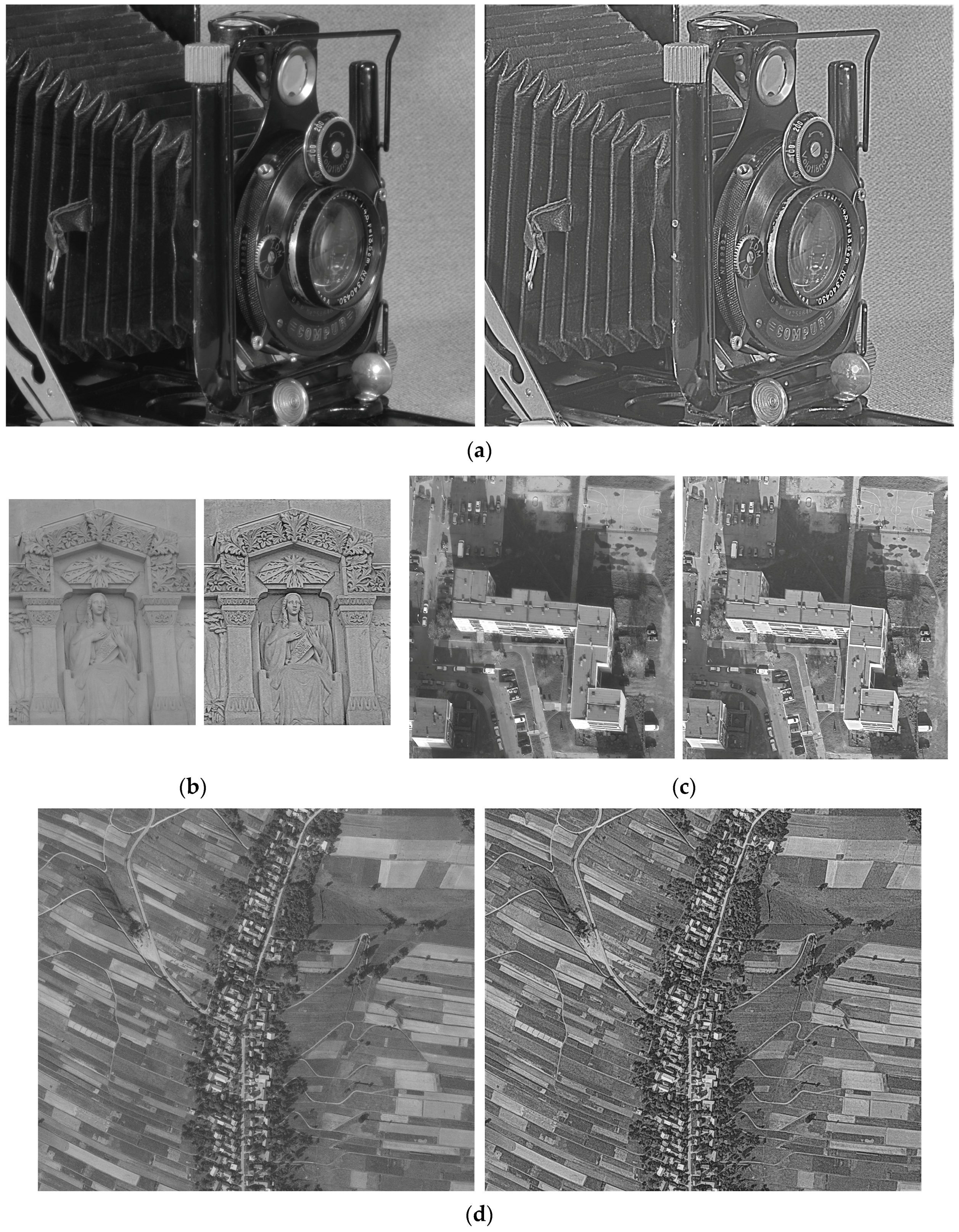
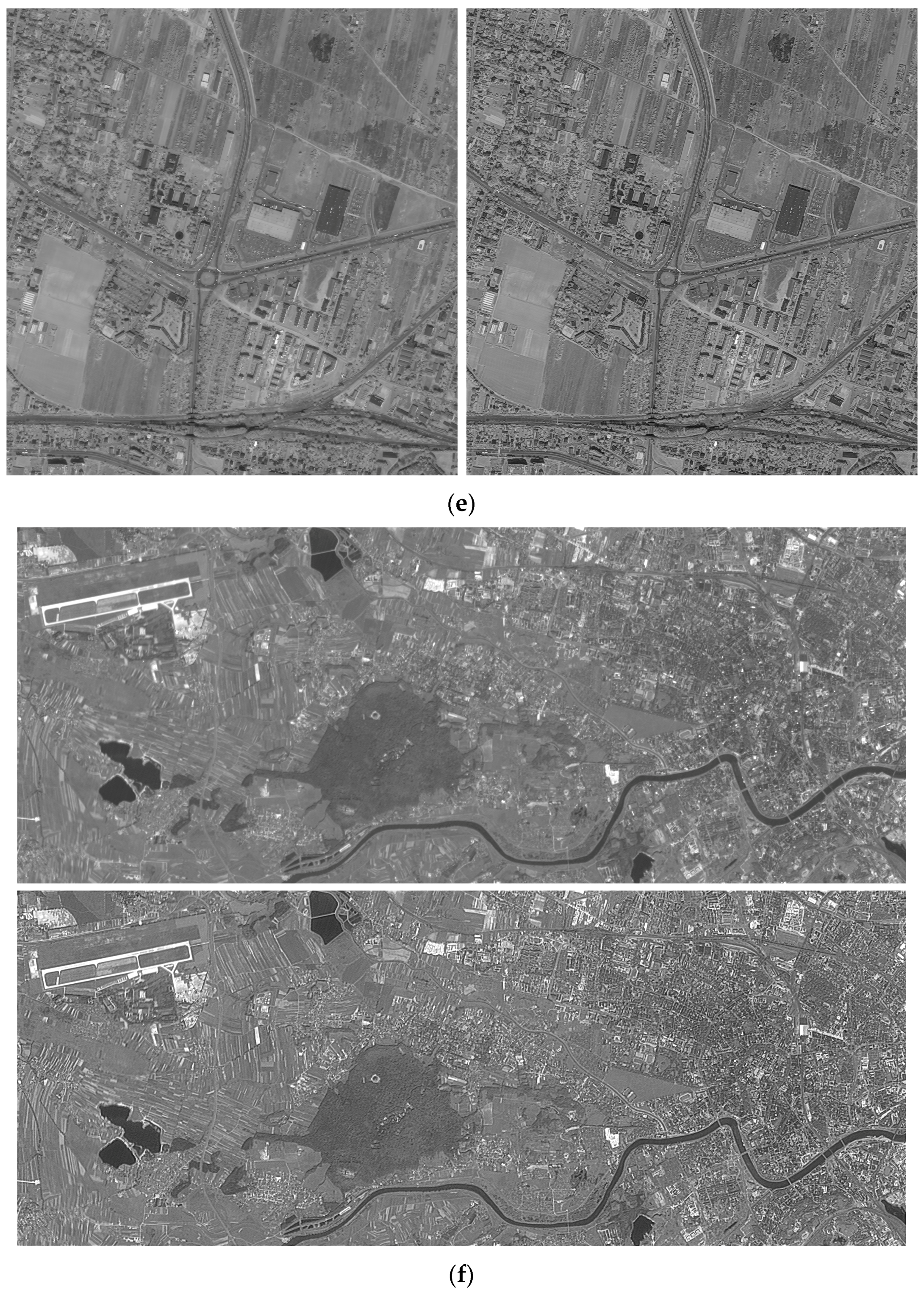
Six images with different characteristics were selected for testing. The first image was taken in a photographer’s atelier by the author with a Nikon D camera, with a 55 mm camera lens, on a tripod and with artificial lighting. The image depicts an old camera made by Voigtländer in 1936 and is called Camera. The second image called Fourvière portrays an architectural detail, and was downloaded from a website maintained by F.A.P. Petitcolas. The third and fourth images are parts of aerial photographs with a ground resolution of about 10 and 42 cm, and are called Estate and Land, respectively. Estate was taken using a Leica airborne digital metric camera by the MGGP Aero company in 2010. Land was obtained using a Wild aerial analogue camera in 1993 and subsequently digitised with a resolution of 1814 dpi using a Leica photogrammetric scanner. The fifth image called Suburb is part of an orthorectified IKONOS scene from 2005, with a resolution of 1 m. The last image, City, has a resolution of 5 m, and is part of an IRS-1C scene from 2000. All the aerial and satellite images depict various areas of the Malopolska region in Poland, whose principal city is Krakow. The first three photographs are colourful (Red, Green, Blue channels) and Land, Suburb and City are panchromatic.
The RGB images were converted into 8-bit greyscale images using the standard mix: 30% R, 59% G and 11% B. Before the wavelet enhancement was performed, the images, apart from Camera, were denoised using the SureShrink method. All test images were enhanced using the WLCE, UM and MSR methods.
2.3. Processing of the WLCE Method
During the experimental work, multiple orthogonal wavelets (Daubechies, Least Asymmetric) were tested, but the Haar wavelet was found to be best suited for edge increasing. It has the shortest support out of the entire family of orthogonal wavelets. As a result, the wavelet detail response at the edge extends only to the immediate vicinity (one position to the left and right for the first level of decomposition).
Prior to enhancing Camera (Figure 1a), it was established that the aim was to improve the visibility of the following minor parts: the barely visible text on the front of the camera, the soft texture of the leather box and the texture of the background (a fabric with a regular fine pattern). The aim of the enhancement of Fourvière (Figure 1b) was to improve the visibility of all the details across the image but especially in the bottom section. In the case of Estate (Figure 1c), the enhancement was focused on the edges in the shadowy area and in the over-exposed area (the building walls). The most important enhancement aim for Land (Figure 1d) was to improve the boundary visibility of the land parcels. In the case of Suburb (Figure 1e), the enhancement was focused on the improvement of vegetation visibility. The aim of the enhancement of City (Figure 1f) was to increase the visibility of linear spatial structures. For all tested images, it was also assumed that the easily visible elements should not be enhanced. Due to the very narrow histogram of DN, the source City image, and its UM enhancement were shown with histogram stretching applied. All other source images and all other enhanced images are presented without stretching. The WLCE and MSR methods use the full range of DN and this method can be called a quasi-stretching.
After a number of attempts it was concluded that the last part of formula (3) can be replaced with a simpler form:
in which first, the details are summed up (k = 1, 2, 3) for level j, and then the sums are scaled with the matrix wj (therefore the scaling functions, represented by matrices, have index j only).
There are two parameters for the PDF-based scaling functions: standard deviation sd and gain g. For the particular detail coefficients d, the over-representation value Δd is calculated in the following manner:
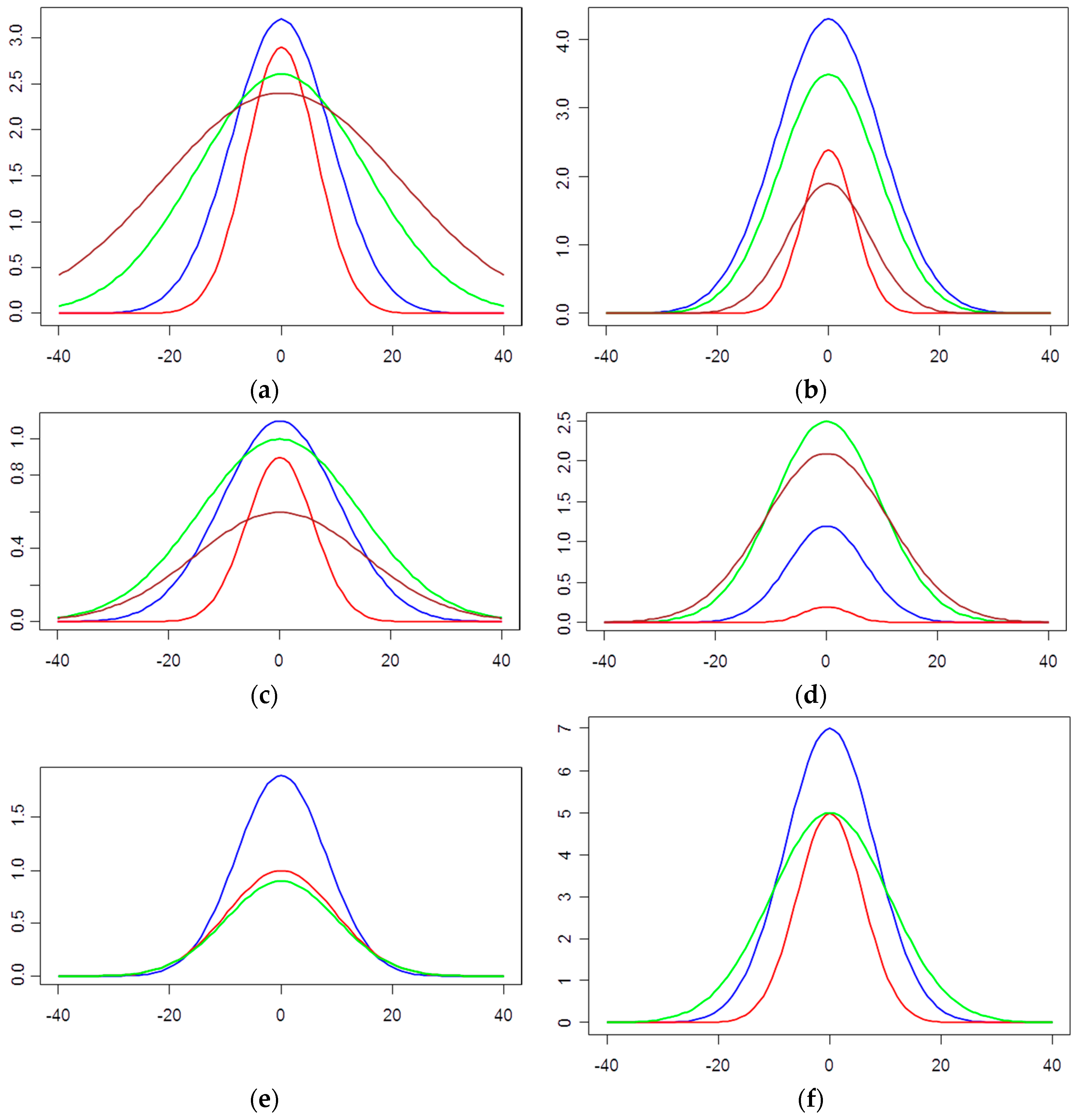
As an initial value of the sd of the PDF, the multiplication of the standard deviation of the particular detail component was assumed to be three. The parameter g equals one and was taken as the first value. The final value of parameters sd and g were chosen empirically in order to achieve the goal of enhancement. It was found that in all four cases the wavelet coefficients that are important for its established objectives extend across as many as four levels of decomposition. After analysing the size of the detail coefficients at different levels for the Camera image, it was concluded that it is necessary to cover the details of the fourth level as widely as possible and quickly attenuate the details of the first level. In a similar empirical way, scaling functions were chosen for the other images. All terrestrial and aerial images had the over-representation applied for four levels of decomposition. In the case of satellite images, only three levels were scaled. The finally selected scaling functions are shown in Figure 2.
3. Results
3.1. Qualitative Analysis of the Results
Figure 3 is an enlargement of a selected portion of the Camera image and makes it possible to compare the results of the WLCE with the results of the UM and the MSR methods. A visual comparison suggests that the proposed method, compared to the UM and MSR, enhances the contrast in a sustainable way and also better eliminates the influence of light. It is also worth mentioning that the WLCE, in comparison to UM, is more effective in the critical areas (small texts, details of the lens housing, including the porous ring). Also, the effect in the reduction of the influence of light is visible for the wavelet enhancement (the background is more uniform).
Comparisons between other test images yielded similar results. The following five figures, Figure 4, Figure 5, Figure 6, Figure 7 and Figure 8, are an enlargement of the selected portion of the Fourviere, the Estate and the Land images respectively. It can be seen that the UM method sharpens both the strong edges, which are visible enough in the original image, as well as the weaker edges. The top of the wavelet-enhanced Fourviere image is quite similar to the UM results. At the bottom, however, the WLCE method gives stronger edge enhancement. There is an obvious visible reduction in the influence of illumination in the case of the Estate image enhanced using wavelet. This is the effect of the transformation of the smooth component (according to the Formula (3)).
A visual assessment of the images compared in Figure 3, Figure 4, Figure 5 and Figure 6 shows a clear improvement of the edge discernibility for all methods, but the WLCE and MSR methods produce a stronger enhancement than UM. However, the MSR method does cause some luminance (Figure 6d—see the brightening of the sculpture’s forehead).
3.2. Quantitative Analysis of the Results
Two measures were used for the quantitative assessment of the enhancement results. The first was entropy, which depicts the amount of information content in the image [1,5,26,42]. All images were first normalised to a DN range of 0–255 in a linear manner. The entropy values are shown in Table 1.
The second analysis is based on the variance ratios calculated between the enhanced images in relation to the source images in the wavelet domain. Initially, a wavelet transform was performed on all compared images using classic UDWT, in order to preserve the energy of the signal during decomposition. The decomposition included five levels, i.e., one level more than during the wavelet enhancement. The ratios are the results of the division variances of wavelet components of the enhanced images compared to the source images. The variance of components were first normalised in relation to the variance of the image. In the images with enhanced edges, the detail variance should be greater than in the source images, and the smooth component should have a smaller variance. It should be noted that the comparison was conducted for variances representing the sum of the variances of all the detail components at a given level of decomposition (d1–d5); this obviously does not apply to the smooth components (s5). Results are depicted in Table 2 and Table 3.
4. Discussion of Results
From a theoretical point of view, higher values of entropy indicate higher visual quality. As has been shown in Table 1, all enhancement methods increase the entropy, but the wavelet and MSR methods more obviously then UM, with the Estate image being the only exception. In this case, however, there is a conflict between the measurement and the visual assessment, especially in the shadowy area, where wavelet and MSR-enhancement methods provide a clearer image. There are three reasons for this: firstly, the enhancement was concentrated only on a part of the image, and entropy was computed for the full frame; secondly, the entropy is not an ideal measure of image visual quality [43]; and thirdly, the model of users’ evaluation of image photometric quality is not fully recognised [44]. A similar conflict between the quantitative and visual assessment can be seen in the entropy of the Camera image: the measurement for MSR is higher but the visual quality is significantly worse than the image enhanced by wavelet (Figure 3—compare the inscription on the front of the camera). It should be mentioned that the wavelet method provides significantly higher entropy for Fourvière, Land, Suburb, City images, and is comparable to the highest value of the other two images.
The image variance is an indicator of image energy and indirectly of local contrast. For all enhancement methods, the variances in the detail components was greater for those images compared to the source images for the first three levels of decomposition, in some cases even for all analysed levels (Table 2 and Table 3, ratios >1). For the wavelet method, stronger detail enhancement was obtained almost on all over-represented levels of decomposition. For not-scaled levels, the ratios are falling and sometimes are lower than one. The only exception is noted for the first two levels of decomposition for Land image. The reason in this case is easy to clarify: the scaling factors for the first two levels were relatively small, as shown in Figure 2d. The smaller wavelet ratios for the smooth component, compared to those from the other methods, shown in the last row of Table 2 and Table 3, was expected. There is evidence of the energy being transferred to the detail components. If the smooth component has a small variance, then we are dealing with the background image. The hypothesis regarding the increase in local contrast was confirmed.
The strongest over-representation has been applied in most cases at the second level of decomposition. Land is the only exception as it is hardly noised and the noise is concentrated on the first level (denoising was not effective enough). In comparison to all other cases, the scaling function for the satellite image City is very strong, as this was the way to stretch the very narrow histogram range. All of the aims for the enhancement of images, specified in Section 2.3, were achieved. Due to the poor quality of source images, the most spectacular results of the WLCE were achieved for Fourvière and City.
Comparison of WLCE with other well-known methods successfully used in image processing shows that the proposed method can achieve comparable and even better enhancement effects. Importantly, wavelet enhancement bears some resemblance to both the UM method (creating the halo effect) and the MSR method (extreme light exposure). The functionality is similar to both reference methods, but wavelet enhancement is more flexible. WLCE makes it possible to achieve the intended purpose: the method enables controlled image enhancement, and the decision to enhance certain contrasts can be made during the selection of scaling function parameters. A visual comparison of enhanced images (Figure 3, Figure 4, Figure 5, Figure 6, Figure 7 and Figure 8) suggests that the WLCE method increases the local contrast but decreases the global contrast. This effect occurs due to the reduced emphasis of the smooth component during reconstruction (Formula (3)). It is also worth mentioning that the global contrast decrease is a result of the reduction of the effects of illumination.
Use of the proposed WLCE method can cause problems when noise is present in the image. The scaling of the wavelet coefficients of the details, specifically the coefficients for the first level, may lead to an increase in noise. In this situation, prior to enhancement, removing the noise is necessary. The methods based on wavelets are the most effective in achieving this.
The increase in the values of some wavelet components and the reduction of the others are de facto disturbances in the image reconstruction phase. As verified in the case of the Haar wavelet, the effects of the disturbance take the form of brightening or dimming within the buffer around the edge. The application of any other wavelet increases the buffer zones, which produces the sensation of artefacts in humans much faster. In the presented method, the results of enhancement must be checked empirically and it is not possible to clearly predict the effects prior to the enhancement. This is a drawback of this method. In practice, however, other enhancement methods like UM and MSR are applied by trial and error as well.
The usage of six images with different characteristics in the research, has made it possible to demonstrate the adaptability of the WLCE method of image enhancement. This has been achieved by scaling particular image features appropriately as required for each particular enhancement.
The studies have shown that most images require noise removal prior to wavelet enhancement. Denoising was unnecessary only in the case where the image was taken in a photographer’s atelier, where camera to object distance was only a few meters. In the case of significantly larger distances, and with the addition of natural light and atmospheric influence, even the usage of professional sensors does not eliminate the noise.
5. Conclusions
The undecimated wavelet transform converts an image into a set of components which express parts in steadily decreasing frequency. The proposed WLCE involves exposing the high-frequency information and attenuating the low-frequency information. However, in addition to the interpretation of the method from the point of view of the frequency analysis of the 2D signal, one can look at the method through the eyes of a person who “reads” the image. In the first phase of the content analysis, the person subconsciously isolates “an item” that appears on “a background.” From this point of view, the proposed method enhances the foreground and weakens the background. Essentially, only the detail coefficients are changed during the reconstruction process. Optionally, however, the smooth components may be changed as well, by linear transformation, so as to weaken its role in the enhanced image. The change of the smooth component may also be forced—this can be applied to the situation where the enhancement of the details results in exceeding the numerical range of brightness for 8-bit images.
The WLCE method, compared to other solutions, is more user oriented, as the user decides which properties of the image should be improved. However, the selection of the scaling function parameters are critical for good quality results. It should be mentioned that the selection of the scaling function parameters must be performed manually for each case. Further development of this method, where the optimal selection of critical parameters is automated, is conceivable, but an indication of where the enhancement is required in the image is likely to remain a manual task; recognising areas as critical for the interpretation of the content is dependent on the purpose for which the image is being used.
Significant limitations of the WLCE method need to be considered, such as its relatively high computational cost and high computer memory usage. Thus, during practical implementation, measures would have to be taken to mitigate these drawbacks. However, this should not be particularly difficult. For very large images, it is possible to carry out operations on separate segments and then release unnecessary memory resources after completing these particular segments.
The visual interpretation of remote sensing images is still important. Furthermore, the visual quality of the images affects the results of the automation (e.g., in land use/cover classification, in image segmentation, image matching). For the automatic processes, the enhanced images with a large range of DN can be stored with any number of bits. The proposed WLCE can be extended to colour images. In order not to increase the calculation load, it would be necessary to use a model that isolates the intensity component and chromatic components (such as Lab, Luv). Then the wavelet enhancement would be applied only to the component of intensity, and the chromatic components would be unchanged or processed using simple means, such as histogram stretching. Verification of this hypothesis requires further detailed research.
Acknowledgments
This research was conducted using funds from the AGH University of Science and Technology Research Grant No. 11.11.150.959.
Conflicts of Interest
The author declares no conflict of interest.
References
- Gonzalez, R.C.; Woods, R.E. Digital Image Processing, 3rd ed.; Prentice Hall: Upper Saddle River, NJ, USA, 2008. [Google Scholar]
- Khellaf, A.; Beghadadi, A.; Dupoisot, H. Entropic Contrast Enhancement. IEEE Trans. Med. Imaging 1991, 10, 589–592. [Google Scholar] [CrossRef] [PubMed]
- Jawerth, B.D.; Hilton, M.L.; Huntsberger, T.L. Local enhancement of compressed images. J. Math. Imaging Vis. 1993, 3, 39–49. [Google Scholar] [CrossRef]
- Hansen, T.; Neumann, H. Neural mechanisms for Representing Surface and Contour Features. In Emergent Neural, Computational Architectures; Wermter, S., Austin, J., Willshaw, D., Eds.; Springer: Heidelberg, Germany, 2001; pp. 139–153. [Google Scholar]
- Pratt, W.K. Digital Image Processing: PIKS Inside, 3rd ed.; Wiley: New York, NY, USA, 2001. [Google Scholar]
- Campbell, F.W. The human eye as an optical filter. Proc. IEEE 1968, 56, 1009–1014. [Google Scholar] [CrossRef]
- Buades, A.; Coll, B.; Morel, J.M. A Review of Image Denoising Algorithms, with a New One. Multiscale Model. Simul. 2005, 4, 490–530. [Google Scholar] [CrossRef]
- Nunez, J.; Otazu, X.; Fors, O.; Prades, A.; Pala, V.; Arbiol, R. Multiresolution-Based Image Fusion with Additive Wavelet Decomposition. IEEE Trans. Geosci. Remote Sens. 1999, 37, 1204–1211. [Google Scholar] [CrossRef] [Green Version]
- Garzelli, A.A. Review of Image Fusion Algorithms Based on the Super-Resolution Paradigm. Remote Sens. 2016, 8, 797. [Google Scholar] [CrossRef]
- Shih, M.-Y.; Tseng, D.-C. A wavelet-based multiresolution edge detection and tracking. Image Vis. Comput. 2005, 23, 441–451. [Google Scholar] [CrossRef]
- Demirel, H.; Anbarjafari, G. IMAGE Resolution Enhancement by Using Discrete and Stationary Wavelet Decomposition. IEEE Trans. Image Process. 2011, 20, 1458–1460. [Google Scholar] [CrossRef] [PubMed]
- Laine, A.; Fan, J.; Yang, W. Wavelets for contrast enhancement of digital mammography. IEEE Eng. Med. Biol. Mag. 1995, 14, 536–550. [Google Scholar] [CrossRef]
- Kim, S.E.; Jeon, J.J.; Eom, I.K. Image contrast enhancement using entropy scaling in wavelet domain. Signal Process. 2016, 127, 1–11. [Google Scholar] [CrossRef]
- Grossmann, A.; Morlet, J. Decomposition of Hardy Functions into Square Integrable Wavelets of Constant Shape. SIAM J. Math. Anal. 1984, 15, 723–736. [Google Scholar] [CrossRef]
- Daubechies, I. Ten Lectures on Wavelets; SIAM: Philadelphia, PA, USA, 1992. [Google Scholar]
- Mallat, S. A Wavelet Tour of Signal Processing; Academic Press: New York, NY, USA, 1998. [Google Scholar]
- Mallat, S. A Theory for Multiresolution Signal Decomposition: The Wavelet Representation. IEEE Trans. Pattern Anal. Mach. Intell. 1989, 11, 674–693. [Google Scholar] [CrossRef]
- Percival, D.B.; Walden, A.T. Wavelet Methods for Time Series Analysis; Cambridge University Press: Cambridge, UK, 2000. [Google Scholar]
- Dutilleux, P. An implementation of the algorithme à trous to compute the wavelet transform. In Wavelets: Time-Frequency Methods and Phase Space; Combes, J.-M., Grossman, A., Tchamitchian, P., Eds.; Springer: Heidelberg, Germany, 1989; pp. 298–304. [Google Scholar]
- Gençay, R.; Selçuk, F.; Whitcher, B. An Introduction to Wavelets and Other Filtering Methods in Finance and Economics; Academic Press: San Diego, CA, USA, 2002. [Google Scholar]
- Fowler, J.E. The Redundant Discrete Wavelet Transform and Additive Noise. IEEE Signal Process. Lett. 2005, 9, 629–632. [Google Scholar] [CrossRef]
- Moulin, P.; Liu, J. Analysis of multiresolution image denoising schemes using generalized Gaussian and complexity schemes. IEEE Trans. Inf. Theory 1999, 45, 909–919. [Google Scholar] [CrossRef]
- Starck, J.-L.; Fadili, J.; Murtagh, F. The Undecimated Wavelet Decomposition and its Reconstruction. IEEE Trans. Image Process. 2007, 16, 297–309. [Google Scholar] [CrossRef] [PubMed]
- Jobson, D.J.; Rahman, Z.; Woodell, G.A. A Multiscale Retinex for Bridging the Gap between Color Images and the Human Observation of Scenes. IEEE Trans. Image Process. 1997, 6, 965–976. [Google Scholar] [CrossRef] [PubMed]
- Rahman, Z.; Jobson, D.J.; Woodell, G.A. Retinex processing for automatic image enhancement. J. Electron. Imaging 2004, 13, 100–110. [Google Scholar]
- Shen, X.; Li, Q.; Tian, Y.; Shen, L. An Uneven Illumination Correction Algorithm for Optical Remote Sensing Images Covered with Thin Clouds. Remote Sens. 2015, 7, 11848–11862. [Google Scholar] [CrossRef]
- Liu, J.; Wang, X.; Chen, M.; Liu, S.; Shao, Z.; Zhou, X.; Liu, P. Illumination and Contrast Balancing for Remote Sensing Images. Remote Sens. 2014, 6, 1102–1123. [Google Scholar] [CrossRef]
- Shen, L.; Bai, L. A review on Gabor wavelets for face recognition. Pattern Anal. Appl. 2006, 9, 273–292. [Google Scholar] [CrossRef]
- Saeedi, J.; Moradi, M.H.; Faez, K. A new wavelet-based fuzzy single and multi-channel image denoising. Image Vis. Comput. 2010, 28, 1611–1623. [Google Scholar] [CrossRef]
- Donoho, D.L.; Johnstone, I.M. Adapting to Unknown Smoothness via Wavelet Shrinkage. J. Am. Stat. Assoc. 1995, 90, 1200–1224. [Google Scholar] [CrossRef]
- Portilla, J.; Strela, V.; Wainwright, M.J.; Simoncelli, E.P. Image Denoising using Scale Mixtures of Gaussians in the Wavelet Domain. IEEE Trans. Image Process. 2003, 12, 1338–1351. [Google Scholar] [CrossRef] [PubMed]
- Luisier, F.; Blu, T.; Unser, M. A New SURE Approach to Image Denoising: Interscale Orthonormal Wavelet Thresholding. IEEE Trans. Image Process. 2007, 16, 593–606. [Google Scholar] [CrossRef] [PubMed]
- Kaiqi, H.; Zhenyang, W.; Qiao, W. Image enhancement based on the statistics of visual representation. Image Vis. Comput. 2005, 23, 51–57. [Google Scholar] [CrossRef]
- Wan, Y.; Shi, D. Joint Exact Histogram Specification and Image Enhancement through the Wavelet Transform. IEEE Trans. Image Process. 2007, 16, 2245–2250. [Google Scholar] [CrossRef] [PubMed]
- Lidong, H.; Wei, Z.; Jun, W.; Zebin, S. Combination of contrast limited adaptive histogram equalisation and discrete wavelet transform for image enhancement. IET Image Process. 2015, 9, 908–915. [Google Scholar] [CrossRef]
- Lu, J.; Healy, D. Contrast enhancement via multiscale gradient transformation. In Proceedings of the IEEE International Conference on Image Processing, Austin, TX, USA, 13–16 November 1994; Volume 2, pp. 482–486.
- Nercessian, S.C.; Panetta, K.A.; Agaian, S.S. Non-Linear Direct Multi-Scale Image Enhancement Based on the Luminance and Contrast Masking Characteristics of the Human Visual System. IEEE Trans. Image Process. 2013, 22, 3549–3561. [Google Scholar] [CrossRef] [PubMed]
- Provenzi, E.; Caselles, V. A Wavelet Perspective on Variational Perceptually-Inspired Color Enhancement. Int. J. Comput. Vis. 2014, 106, 153–171. [Google Scholar] [CrossRef]
- Peli, E. Contrast in complex images. J. Opt. Soc. Am. A 1990, 7, 2032–2040. [Google Scholar] [CrossRef] [PubMed]
- Martins, N.; Pereira, C.; Ferreira, M. Digital mammograms contrast enhancement using wavelets—A comparative study. In Proceedings of the 2014 IEEE International Symposium on Medical Measurements and Applications (MeMeA), Lisbon, Portugal, 11–12 June 2014; pp. 1–6.
- Łoza, A.; Bull, D.R.; Hill, P.R.; Achim, A.M. Automatic contrast enhancement of low-light images based on local statistics of wavelet coefficients. Digit. Signal Process. 2013, 23, 1856–1866. [Google Scholar] [CrossRef]
- Tsai, D.-Y.; Lee, Y.; Matsuyama, E. Information Entropy Measure for Evaluation of Image Quality. J. Digit. Imaging 2008, 21, 338–347. [Google Scholar] [CrossRef] [PubMed]
- Pluim, J.P.W.; Maintz, J.B.A.; Viergever, M.A. Mutual-information-based registration of medical images: A survey. IEEE Trans. Med. Imaging 2003, 22, 986–1004. [Google Scholar] [CrossRef] [PubMed]
- Tarko, A.; de Bruin, S.; Fasbender, D.; Devos, W.; Bregt, A.K. Users’ Assessment of Orthoimage Photometric Quality for Visual Interpretation of Agricultural Fields. Remote Sens. 2015, 7, 4919–4936. [Google Scholar] [CrossRef] [Green Version]
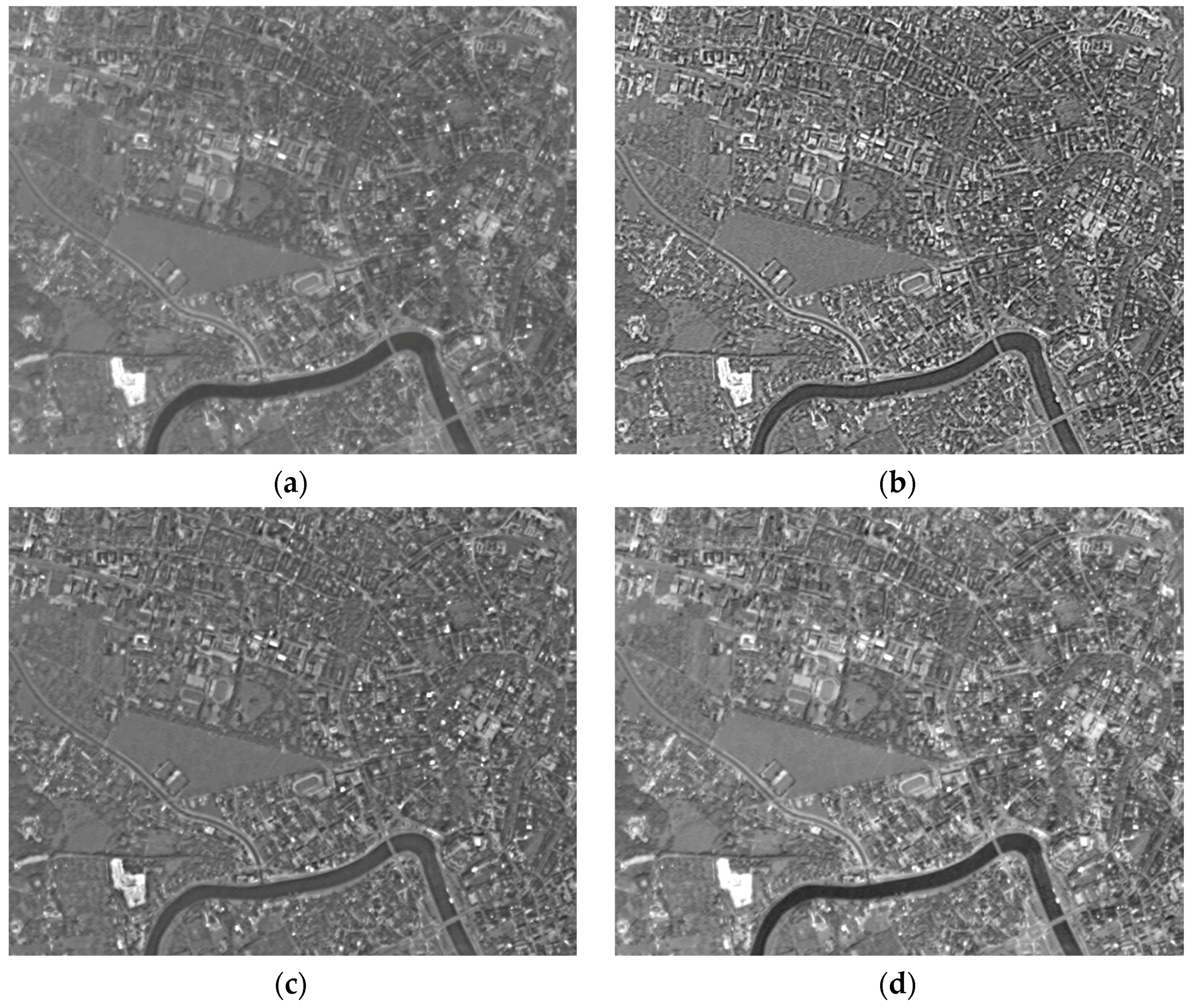
Figure 1.
The general comparison of the source images (left/top) and the wavelet-enhanced images (right/bottom): Camera (a); Fourvière (b); Estate (c); Land (d); Suburb (e); City (f).
Figure 1.
The general comparison of the source images (left/top) and the wavelet-enhanced images (right/bottom): Camera (a); Fourvière (b); Estate (c); Land (d); Suburb (e); City (f).


Figure 2.
Functions used for scaling the wavelet coefficients of the decomposition levels one (red), two (blue), three (green), four (brown) of the images Camera (a); Fourvière (b); Estate (c); Land (d); Suburb (e); City (f).
Figure 2.
Functions used for scaling the wavelet coefficients of the decomposition levels one (red), two (blue), three (green), four (brown) of the images Camera (a); Fourvière (b); Estate (c); Land (d); Suburb (e); City (f).

Figure 3.
Detailed comparison of the Camera image and the enhanced images: source image (a); WLCE (b); UM (c); MSR (d).
Figure 3.
Detailed comparison of the Camera image and the enhanced images: source image (a); WLCE (b); UM (c); MSR (d).
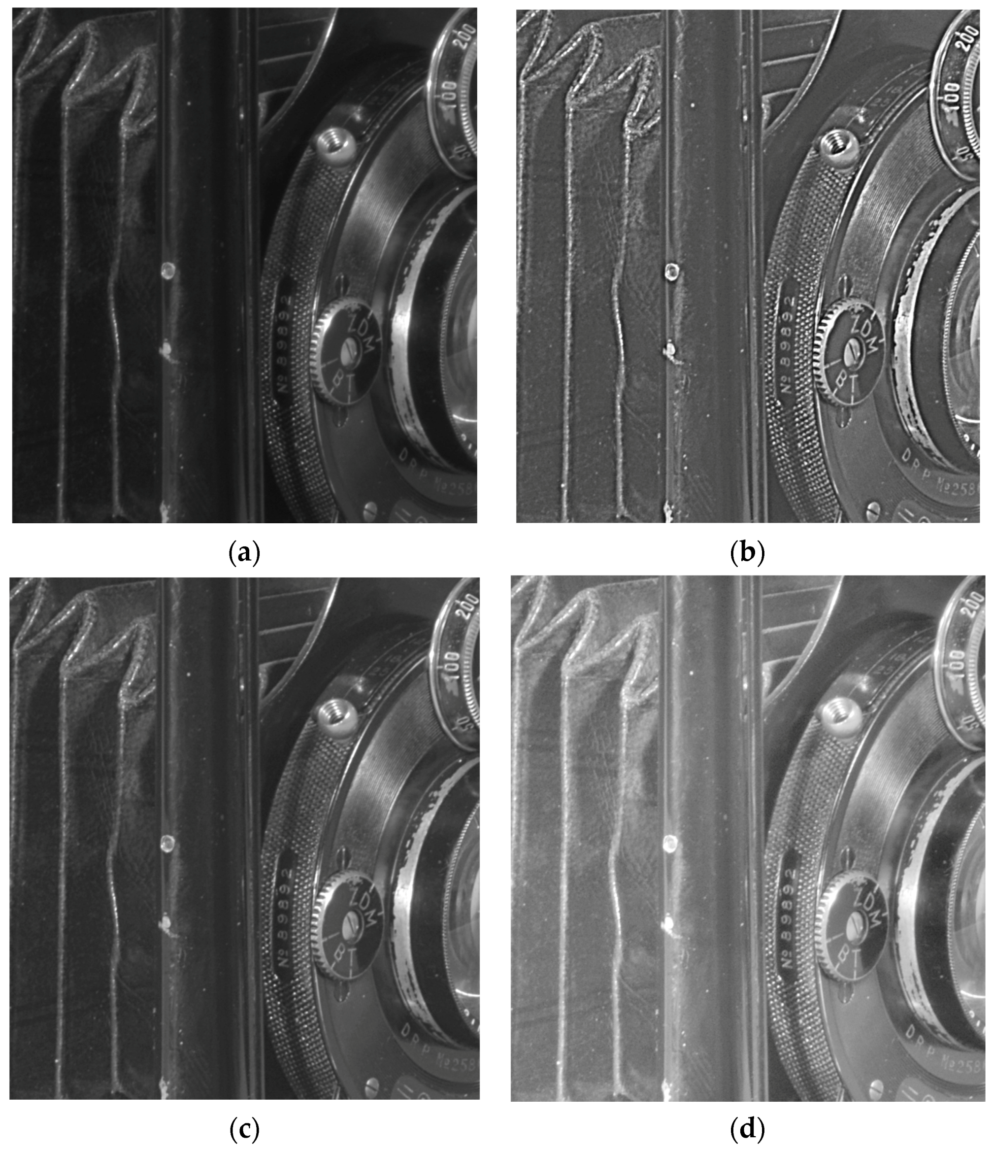
Figure 4.
Detailed comparison of the Fourvière image and the enhanced images: source image (a); WLCE (b); UM (c); MSR (d).
Figure 4.
Detailed comparison of the Fourvière image and the enhanced images: source image (a); WLCE (b); UM (c); MSR (d).
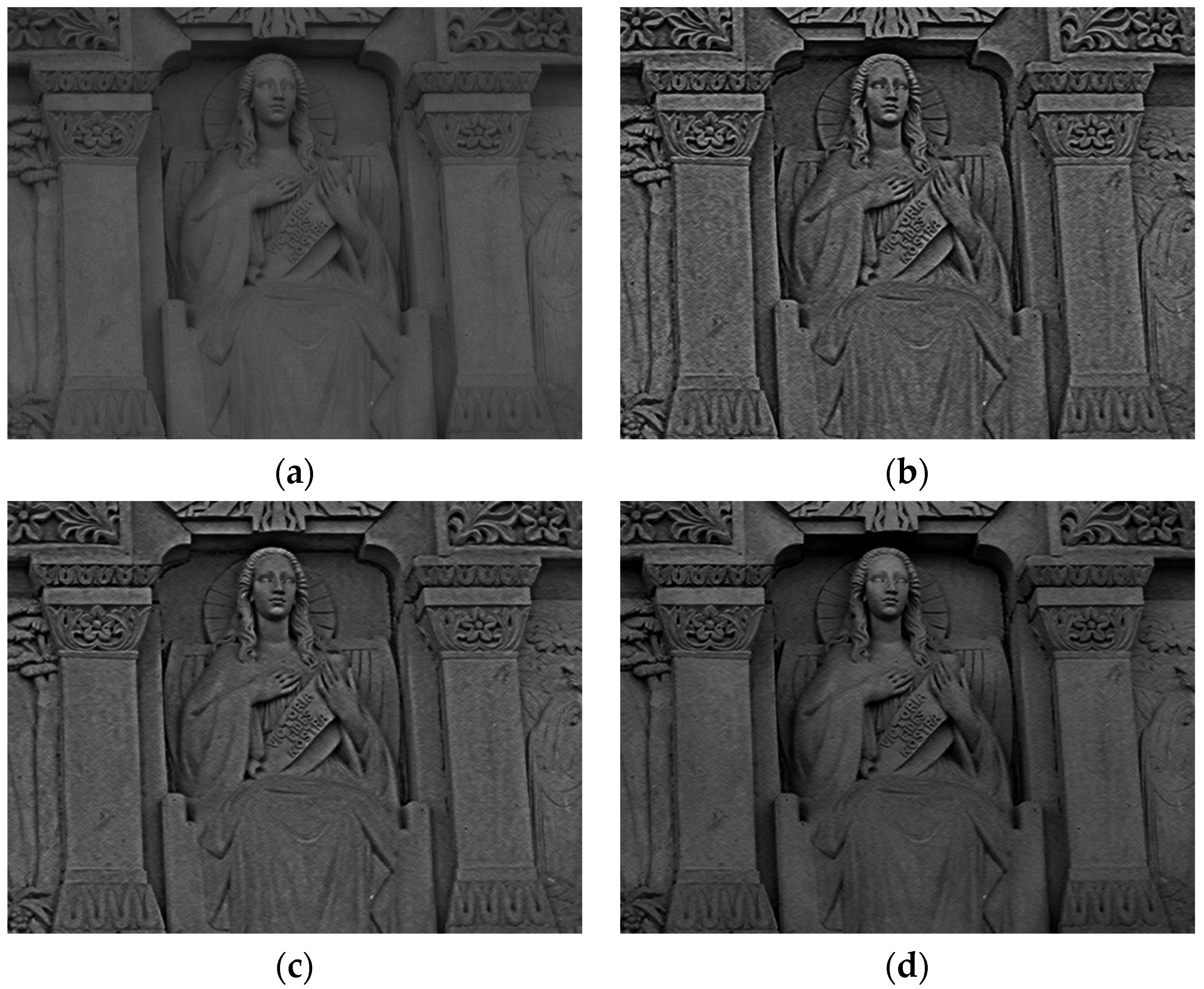
Figure 5.
Detailed comparison of the Estate image and the enhanced images: source image (a); WLCE (b); UM (c); MSR (d).
Figure 5.
Detailed comparison of the Estate image and the enhanced images: source image (a); WLCE (b); UM (c); MSR (d).
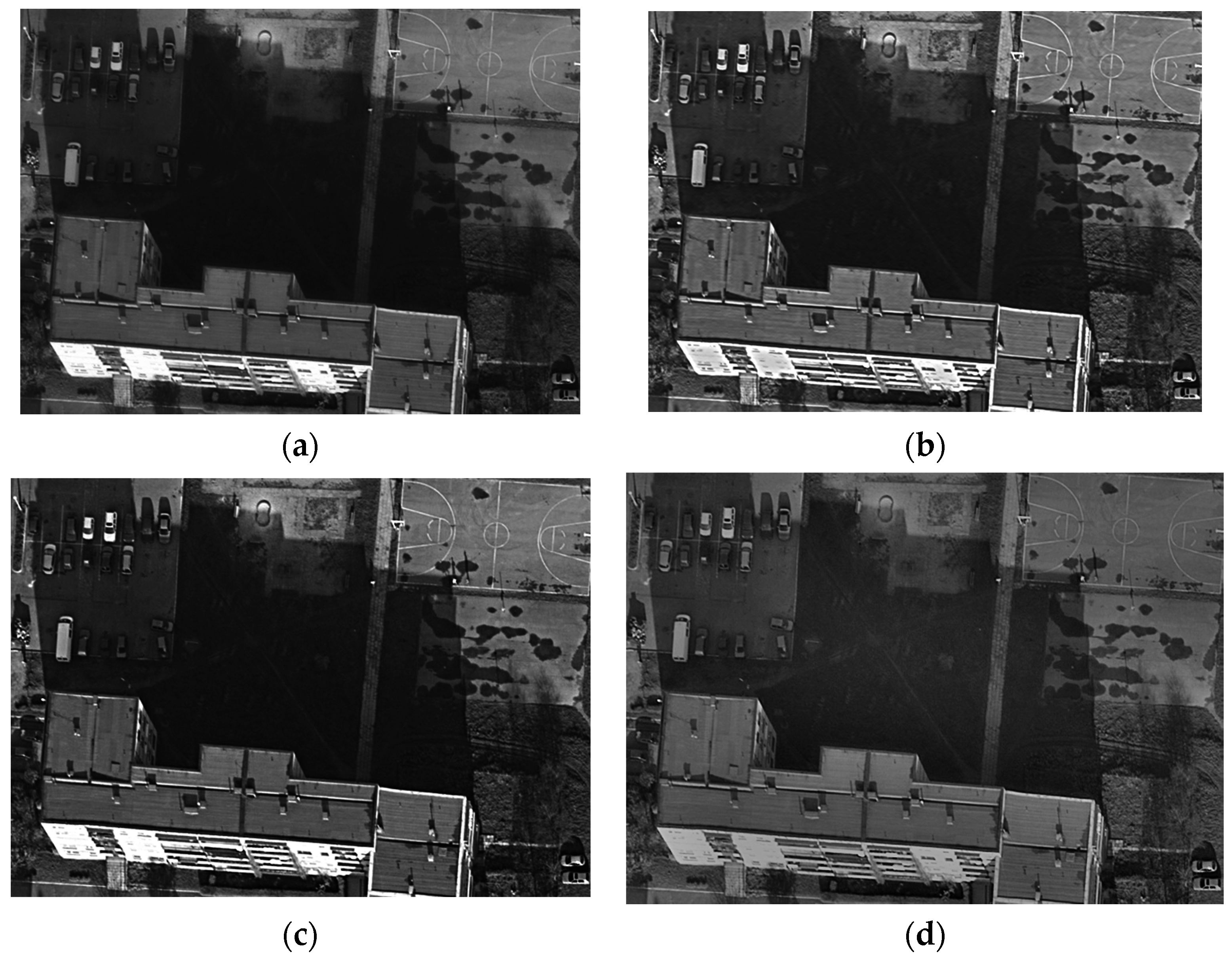
Figure 6.
Detailed comparison of the Land image and the enhanced images: source image (a); WLCE (b); UM (c); MSR (d).
Figure 6.
Detailed comparison of the Land image and the enhanced images: source image (a); WLCE (b); UM (c); MSR (d).
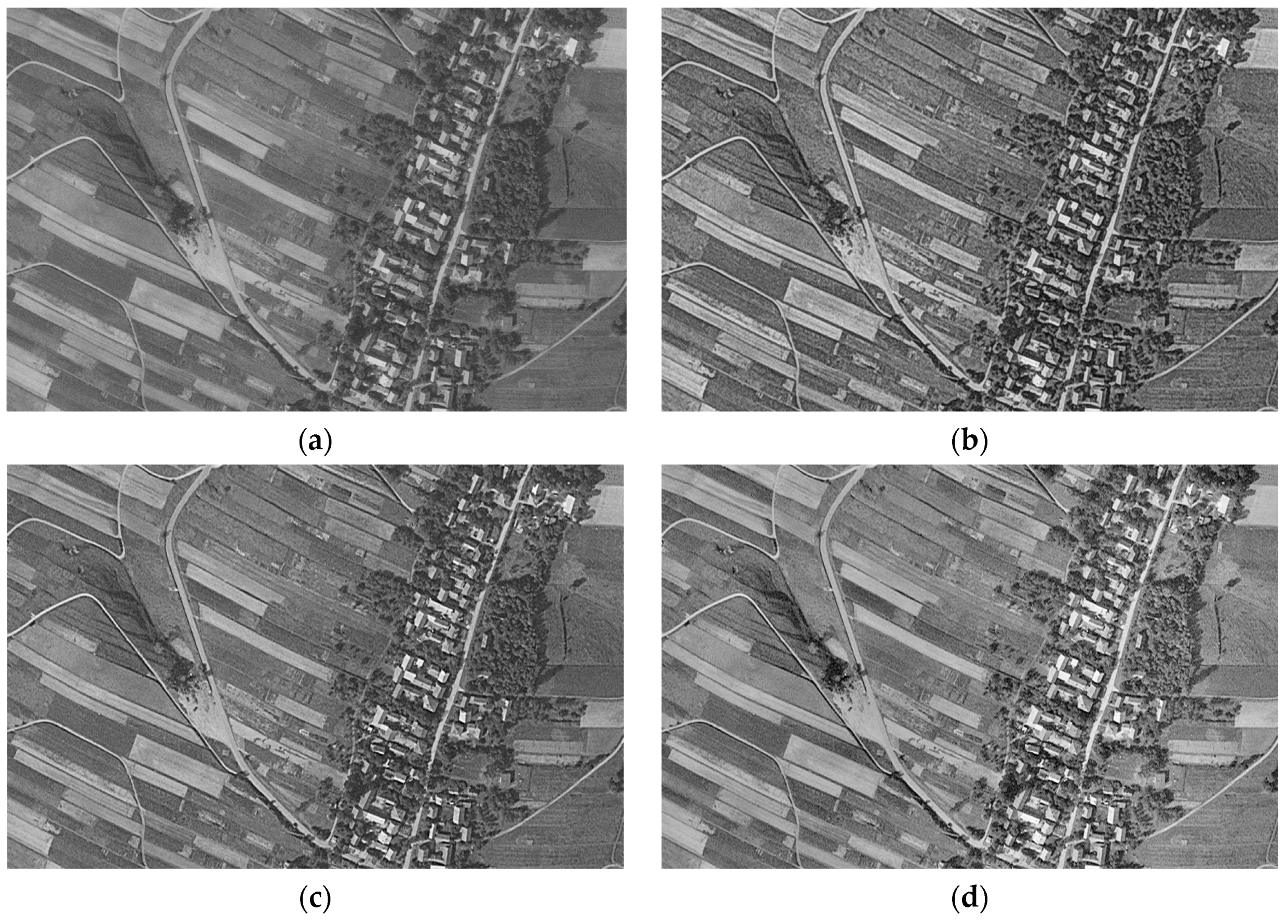
Figure 7.
Detailed comparison of the Suburb image and the enhanced images: source image (a); WLCE (b); UM (c); MSR (d).
Figure 7.
Detailed comparison of the Suburb image and the enhanced images: source image (a); WLCE (b); UM (c); MSR (d).
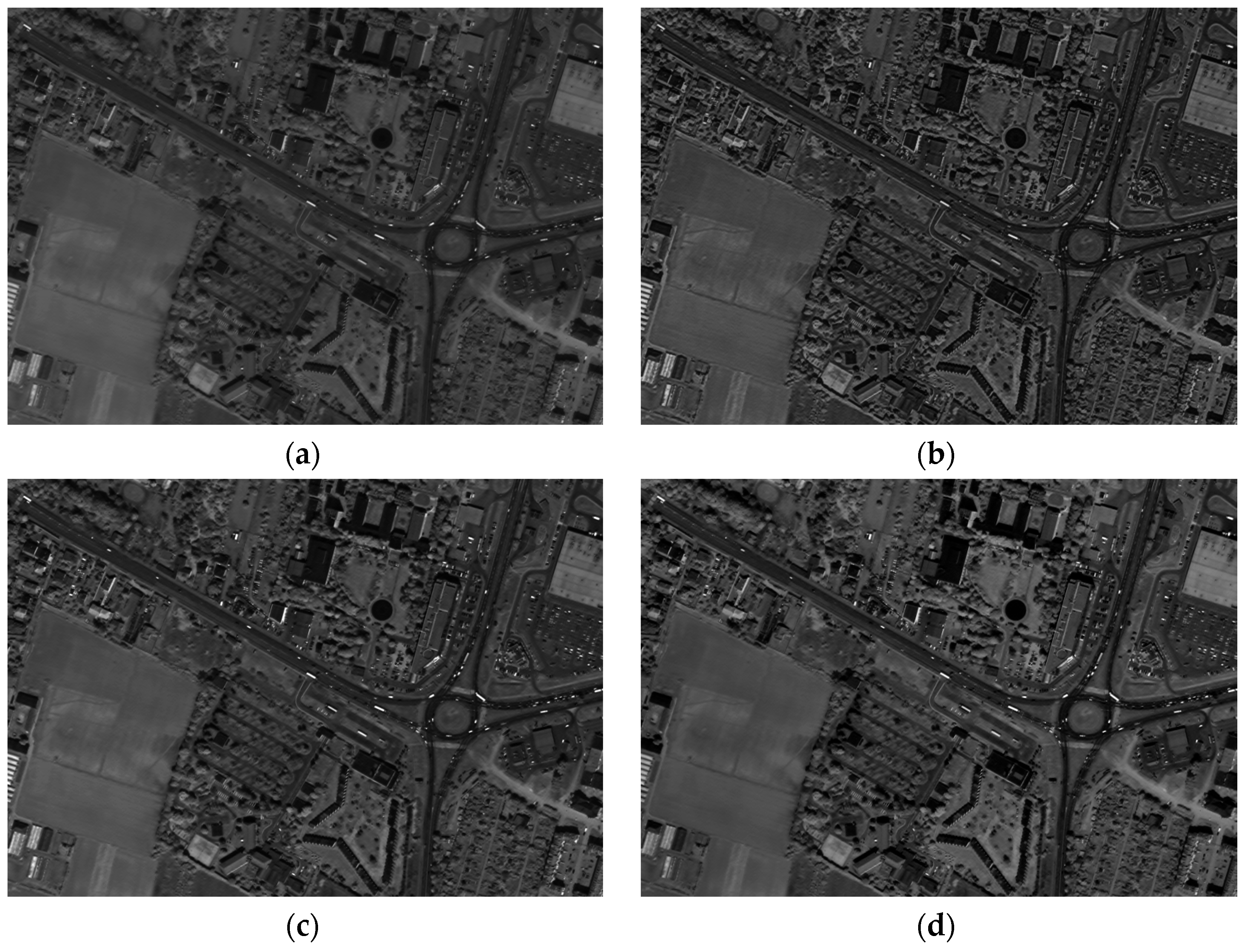
Figure 8.
Detailed comparison of the City image and the enhanced images: stretched source image (a); WLCE (b); stretched UM (c); MSR (d).
Figure 8.
Detailed comparison of the City image and the enhanced images: stretched source image (a); WLCE (b); stretched UM (c); MSR (d).


| Test Image | Source | WLCE | UM | MSR |
|---|---|---|---|---|
| Camera | 6.67 | 7.07 | 6.80 | 7.10 |
| Fourvière | 5.78 1 | 6.85 | 6.56 | 6.71 |
| Estate | 7.10/7.11 2 | 7.16 | 7.17 | 7.02 |
| Land | 6.78 1 | 7.30 | 7.09 | 7.21 |
| Suburb | 6.43 1 | 6.82 | 6.70 | 6.74 |
| City | 5.29 1 | 6.88 | 6.12 | 6.76 |
1 denoised image was used as source image for all enhancement methods; 2 denoised image was used as source image only for wavelet enhancement. The maximum entropy values are in bold.
Table 2.
Comparison of variance ratios in the wavelet domain in relation to source images (Camera, Fourvière, Estate).
| Wav. Component | Camera | Fourviere | Estate | ||||||
|---|---|---|---|---|---|---|---|---|---|
| WLCE | UM | MSR | WLCE | UM | MSR | WLCE | UM | MSR | |
| d1 | 8.71 | 1.55 | 3.36 | 2.97 | 2.46 | 1.89 | 2.50 | 2.06 | 2.22 |
| d2 | 8.50 | 1.58 | 3.26 | 2.75 | 2.38 | 1.74 | 2.54 | 1.94 | 1.93 |
| d3 | 7.42 | 1.51 | 3.11 | 2.22 | 2.13 | 1.49 | 2.38 | 1.75 | 1.55 |
| d4 | 4.92 | 1.31 | 2.97 | 1.35 | 1.46 | 1.24 | 1.71 | 1.34 | 1.26 |
| d5 | 2.12 | 1.10 | 2.88 | 0.68 | 0.73 | 1.10 | 0.99 | 0.96 | 1.14 |
| s5 | 0.62 | 0.97 | 0.76 | 0.30 | 0.37 | 0.62 | 0.58 | 0.77 | 0.76 |
Table 3.
Comparison of variance ratios in the wavelet domain in relation to source images (Land, Suburb, City).
| Wav. Component | Land | Suburb | City | ||||||
|---|---|---|---|---|---|---|---|---|---|
| WLCE | UM | MSR | WLCE | UM | MSR | WLCE | UM | MSR | |
| d1 | 1.80 | 1.99 | 2.48 | 2.17 | 1.45 | 1.35 | 2.94 | 1.88 | 1.33 |
| d2 | 1.96 | 1.92 | 2.17 | 1.96 | 1.42 | 1.30 | 2.60 | 1.84 | 1.29 |
| d3 | 2.01 | 1.74 | 1.72 | 1.45 | 1.33 | 1.25 | 1.85 | 1.74 | 1.22 |
| d4 | 1.63 | 1.35 | 1.37 | 0.92 | 1.12 | 1.18 | 0.88 | 1.41 | 1.14 |
| d5 | 1.03 | 0.95 | 1.18 | 0.67 | 0.86 | 1.12 | 0.51 | 0.84 | 1.10 |
| s5 | 0.60 | 0.71 | 0.62 | 0.55 | 0.69 | 0.64 | 0.48 | 0.38 | 0.74 |
© 2017 by the author; licensee MDPI, Basel, Switzerland. This article is an open access article distributed under the terms and conditions of the Creative Commons Attribution (CC-BY) license (http://creativecommons.org/licenses/by/4.0/).
Share and Cite
MDPI and ACS Style
Pyka, K. Wavelet-Based Local Contrast Enhancement for Satellite, Aerial and Close Range Images. Remote Sens. 2017, 9, 25. https://doi.org/10.3390/rs9010025
AMA Style
Pyka K. Wavelet-Based Local Contrast Enhancement for Satellite, Aerial and Close Range Images. Remote Sensing. 2017; 9(1):25. https://doi.org/10.3390/rs9010025
Chicago/Turabian StylePyka, Krystian. 2017. "Wavelet-Based Local Contrast Enhancement for Satellite, Aerial and Close Range Images" Remote Sensing 9, no. 1: 25. https://doi.org/10.3390/rs9010025
Note that from the first issue of 2016, this journal uses article numbers instead of page numbers. See further details here.