Article

A Shape-Adjusted Tridimensional Reconstruction of Cultural Heritage Artifacts Using a Miniature Quadrotor

1
Aix Marseille Univ, CNRS, ISM, Inst Movement Sci, Marseille 13009, France
2
UMR 3495 Modèles et simulations pour l’Architecture et le Patrimoine (MAP), CNRS, French Ministry of Culture and Communication (MCC), Marseille 13009, France
*
Author to whom correspondence should be addressed.
Remote Sens. 2016, 8(10), 858; https://doi.org/10.3390/rs8100858
Submission received: 28 July 2016 / Revised: 28 September 2016 / Accepted: 12 October 2016 / Published: 20 October 2016
(This article belongs to the Special Issue Remote Sensing for Cultural Heritage)

Abstract

:
The innovative automated 3D modeling procedure presented here was used to reconstruct a Cultural Heritage (CH) object by means of an unmanned aerial vehicle. Using a motion capture system, a small low-cost quadrotor equipped with a miniature low-resolution Raspberry Pi camera module was accurately controlled in the closed loop mode and made to follow a trajectory around the artifact. A two-stage process ensured the accuracy of the 3D reconstruction process. The images taken during the first circular trajectory were used to draw the artifact’s shape. The second trajectory was smartly and autonomously adjusted to match the artifact’s shape, then it provides new pictures taken close to the artifact and, thus, greatly improves the final 3D reconstruction in terms of the completeness, accuracy and quickness, in particular where the artifact’s shape is complex. The results obtained here using close-range photogrammetric methods show that the process of automated 3D model reconstruction based on a robotized quadrotor using a motion capture system is a realistic approach, which could provide a suitable new digital conservation tool in the cultural heritage field.

Graphical Abstract

1. Introduction

Reality-based modeling of Cultural Heritage (CH) objects, such as architectural features and archaeological fragments, has been attracting attention as a means of promoting conservation, documentation and even restoration. One example is the digital Michelangelo project [1], which pioneered the use of computer graphics in the CH domain. Many costly technologies developed for digital sampling purposes, such as 3D scanning methods, can be used for 3D digitization of CH artifact [2,3,4]. Recent technologies for creating reality-based digital footprints have provided researchers with high resolution, high-precision and the latest easy-to-use tools. 3D scanning devices and algorithms have made automated image acquisition and processing easily accessible. The improved efficiency of close-range photogrammetric methods in terms of their completeness, accuracy and quickness should lead to the development of flexible frameworks for using these new surveying techniques to transmit knowledge around the world. The complete automation of the whole 3D digitization pipeline will soon make it possible to create huge collections of digital models, and the future development of reproducible processes will no doubt open new paths for monitoring the aging of CH artifacts.
From the practical point of view, projects for the digitization of our CH will have to take the available time, lighting conditions and transportation possibilities into account. Projects of this kind will therefore require low-cost scanning devices and inexpensive 3D acquisition methods based on digital photography. Projects of this kind may therefore require low-cost scanning devices and inexpensive 3D acquisition methods based on digital photography. However, depending on the requirements of the CH reconstruction, it is well established that low-cost solutions are not always the best ones compared to the relatively low-cost solutions. In [5], an innovative low-cost, open-source automated prototype including both hardware and software for the large-scale 3D acquisition of images of archaeological remains was presented. However, previous studies on the automation of data acquisition systems were performed on a restricted set of CH objects with similar morphological features and dimensions. The approach presented in the present paper could lead to the development of an adaptive procedure, which is applicable to all contexts, dimensions and shapes using the benefits of miniature Unmanned Aerial Vehicle (UAV) data acquisition and processing methods and devices. The advanced automatic image processing pipeline based on the free open-source MicMac-Apero toolchain presented in [6,7,8] is an important step forward in view of its advanced parameter tuning process and the reliability of its 3D reconstruction performances. One issue which constantly arises with digital photogrammetric methods is the quality of the reconstruction, which depends on parameters, such as the texture of the objects targeted, their scale and their optical characteristics. A reference scale of features has to be used to convert the digital data collected into an absolute spatial reference system. Dense stereo-matching is usually performed on an unknown relative scale until the operator has introduced at least one real ground-truth measurement. In addition, the quality of digital photogrammetry depends greatly on the camera work and the viewpoint: it is usually very difficult in fact to cover the entire targeted object.
In robotic applications, an autonomous robotic 3D modeling system that is able to completely scan objects of any shape has been presented in [9]. The robot is moved along a continuous scan path while a statue is being scanned with the attached laser stripe profiler. UAVs are another field in which some interesting new methods are developing that can be applied to photogrammetry. In [10], a specific operational pipeline was tested in the Theater in Pompeii (Italy), based on the use of unmanned airborne vehicles. The aim of this study was to combine the flying abilities and skills of UAVs with the latest 3D digitization methods. A method is presented for carrying out fast 3D reconstruction on cultural heritage treasures with a small, inexpensive photographic sensor and an UAV, which was tested in a flight test arena, which was used for conducting experiments in the field of aerial robotics [11,12]. We also describe the steps in an automated process designed for these reconstruction purposes. In particular, the shape of the object of interest derived thanks to the acquisition during the first trajectory is used to generate the complex shape of the second robot’s trajectory that hugs the complex shape of the artifact to provide a new set of pictures taken from a new viewpoint, most of the time closer to the artifact. The design of the data acquisition protocol is optimized to deliver photographs of sufficiently high quality to accurately produce the 3D documentation of the artifact. The hardware and software used for the image acquisition and to generate clouds of points are presented in Section 2. The 3D reconstruction procedure is described in Section 2.4, and the experimental results are presented in Section 3.

2. Materials and Methods

2.1. A Quadrotor for an Automated Photogrammetric 3D Reconstruction System

All of the following experiments were carried out with the replica of the capital of an Ionic column (height: ∼0.4 m; width: ∼0.5 m; side length: ∼0.6 m) shown in Figure 1, in the 6 × 8 × 6 m 3 flying arena in Marseilles, which is equipped with 17 Vicon cameras. The 17 motion capture cameras are used to get the absolute positions and the velocities of the flying robot in real time and therefore, to precisely estimate the position of the flying robot in the arena. In addition, the 17 motion capture cameras help scaling the 3D reconstruction by giving the position of the cameras onboard the quadrotor. More specifically, this section includes a description of the system and the software used to perform the 3D reconstruction of the capital.

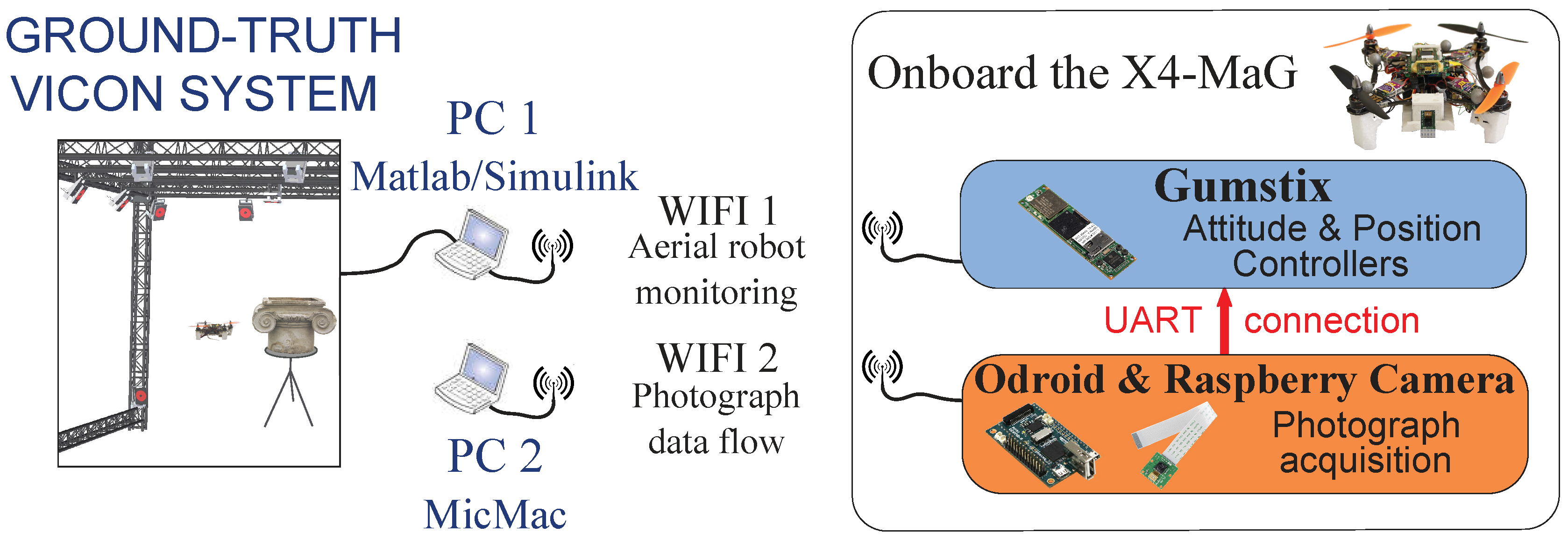
2.2. Hardware Presentation

Since the heritage object targeted must not be damaged, one of the challenges in this project was to use a stable, lightweight platform for taking in-flight photographs.
Figure 2 shows the X4-MaG quadrotor used for the photographic acquisition of the capital, which was first presented in [13] in the form of a small, low-cost, open-source vehicle. The system is not equipped with a GPS system, as the flying arena equipped with 17 cameras-based motion capture system is the positioning system. The quadrotor was equipped here with a Gumstix Overo, an embedded high level controller programmed via the MATLAB/Simulink toolbox RT-MaG [14]. This powerful computer-on-module is able to run Simulink models in real time using the RT-MaG toolbox. Another Simulink model is run in real time on a host computer. The host model sends setpoints by WiFi to the embedded Gumstix, can be used to tune control parameters and monitors the vehicle’s position. The quadrotor is stabilized in pitch and roll thanks to its onboard Inertial Measurement Unit (IMU), and its trajectory can therefore be fully piloted via MATLAB/Simulink from the ground station. It can be accurately located thanks to its 5 marker spheres and the external Vicon motion capture system with which the flying arena is equipped. This ground-truth device provides the robot’s position and is involved in a closed loop control process.
Given the low maximum payload allowance of the X4-MaG quadrotor (∼100 grams), a light Raspberry Camera Module and an Odroid W board were used for the photograph acquisition (see Figure 2). The camera module specifications are detailed in Table 1.
The camera module weighs 3 grams: it has a resolution of 5 Mpx, a field of view of ( 53 . 50 ± 0 . 13 ) × ( 41 . 41 ± 0 . 11 ) degrees and a sensor image area of 3 . 76 × 2 . 74 mm 2 . The camera has been calibrated using the Fraser self-calibration model [15]. Nevertheless, no color calibration has been processed. The initial calibration dataset has been acquired in the optimum context with regards the camera parameters and the lighting condition with a calibration test object made for self-calibration using a random RGB pattern. The result is depicted in the second table in Section 3 with a residue equal to 0.37 px. The 15-gram Odroid W board equipped with a WiFi dongle sends pictures directly to the host station via FTP transfer and makes it possible to tune the Raspberry camera module parameters, including gain (ISO), manual white balance, image quality and shutter speed. It was decided to use two different WiFi connections to improve the speed of the FTP transfer.
Figure 3 shows the connections between the various systems used in the reconstruction.
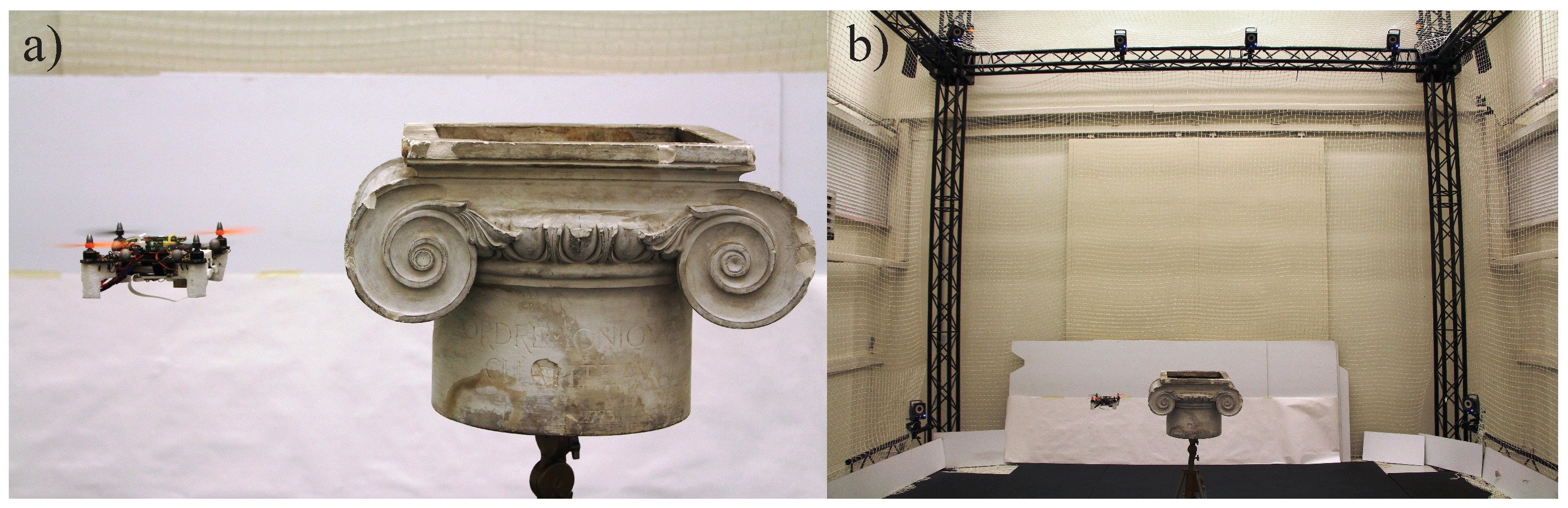
  • A Vicon motion capture system accurately determines the position and orientation of the robot at a frequency of 500 Hz. The round-trip latency (the time taken to travel through the local Ethernet network) between the computer and the VICON® system is very short (<12 ms).
  • A ground station PC 1 runs a Simulink host model in real time using QUARC® software (from Quanser): via WiFi 1, the Simulink-based program sends the 3D position given by the Vicon system to the high level controller onboard the quadrotor. It also monitors the robot’s position and sends setpoints to the embedded quadrotor autopilot.
  • A ground station PC 2 equipped with MicMac receives via WiFi 2 the pictures of the capital taken in flight from the Odroid and the orientation files from PC 1. All of the MicMac calculations and point cloud generation processes were carried out in this ground station called PC 2.
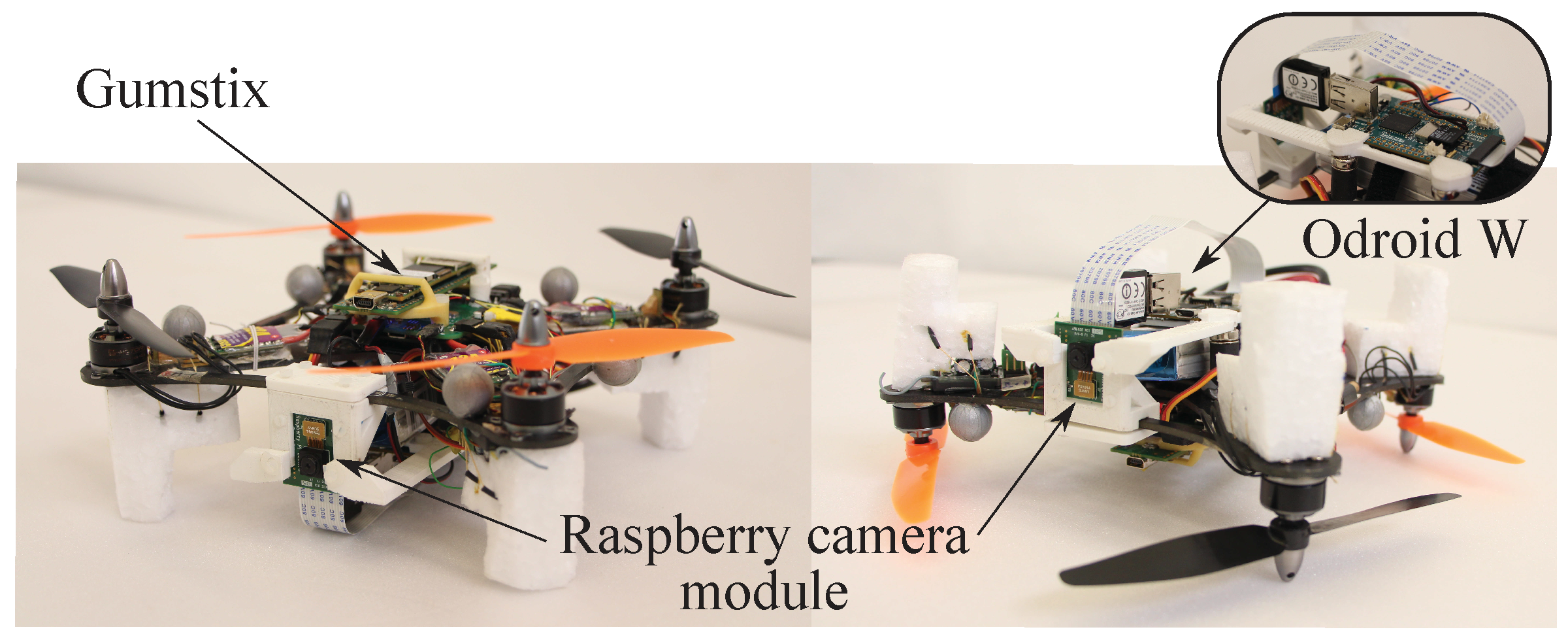
  • the X4-MaG quadrotor with a Gumstix Overo computer-on-Module that receives its 3D position and setpoints from PC 1 and can compute its trajectory autonomously. An Odroid W board equipped with a Raspberry Camera Module takes pictures of the capital and sends the inflight photographs to PC 2 by WiFi 2. The Odroid board also communicates with the Gumstix thanks to a UART serial connection and enables us to record the camera’s position while the photograph acquisition is being performed.

2.3. MicMac: A Tool for Photogrammetric 3D Reconstruction

The latest tools for the dense matching of the APERO/MICMAC photogrammetric toolchain were used to enhance the automation of the data processing. This open-source solution provides a flexible framework that has been tuned to get the optimum result possible with this experimental data acquisition procedure. However, MicMac still uses the classical image-based 3D modeling steps. The theoretical pipeline consists of:
  • Tie-point extraction (using the/an SIFT algorithm) and image-pair recognition,
  • Internal and external calibrations and global orientation of each image based on bundle adjustment,
  • Dense image matching, resulting in the final point cloud.
For each step, optimized parameters have been set in order to reduce the computation time while increasing the robustness and ensure a reasonable level of accuracy. The whole pipeline was compiled in shell script to obtain fully automatic data processing and a reproducible process.

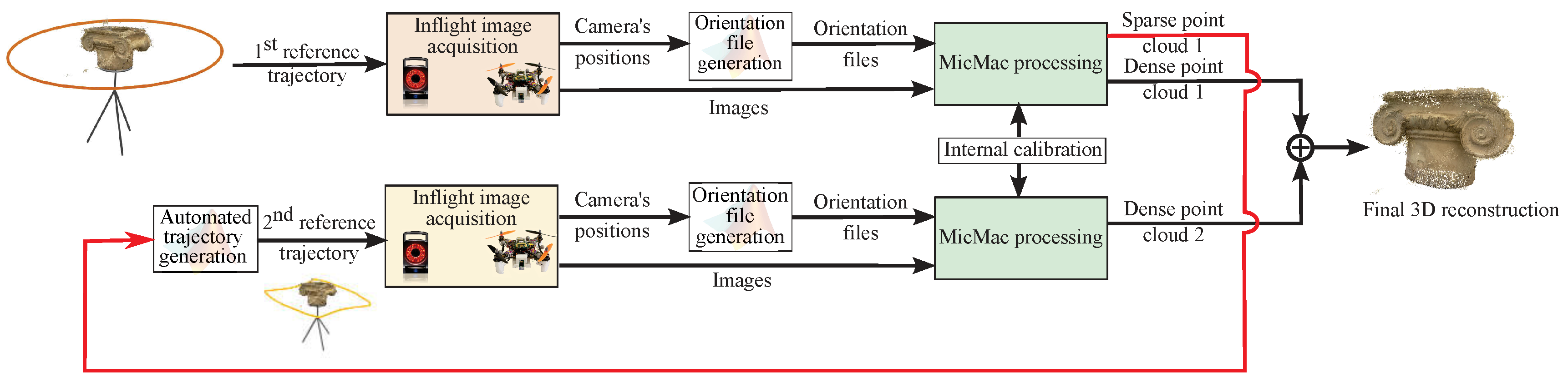
2.4. 3D Reconstruction Procedure

In this section, it is proposed to present the 3D reconstruction method used on the capital. The robot’s trajectories and the photogrammetric algorithms will be described. The picture acquisition procedure was divided into two steps. An initial trajectory was performed in order to obtain a sparse point cloud and feedback about the object’s shape and position. A second trajectory was then performed closer to the capital, in which more detailed pictures were obtained using the information collected in the first trajectory.

2.4.1. Overview of the Procedure

The 3D reconstruction method used is presented in Figure 4. Two sets of 180 photographs were used to obtain the final reconstruction: one set resulting from the original circular trajectory described in Section 2.4.2 and the other set resulting from the induced trajectory described in Section 2.4.3. Pictures were taken approximately every 2 s to ensure good coverage of the object targeted and acceptable quality of the images. As soon as the photos had been taken, they were immediately transferred to the MicMac ground station to be processed. Since the MicMac software (operating in the fully automatic mode) defined a relative spatial reference system, MicMac had to be provided with the camera’s position given by the Vicon system in an absolute spatial reference system. The camera lens was previously internally calibrated on a self-calibration rig in terms of intrinsic parameters and deformations. This calibration step aimed to minimize the undesirable effects of the in-flight photo-shooting (such as vibrations, motion-blur, etc.) using the Fraser model [15]: the bundle adjustment and a final reprojection error of 0.37 pixel were achieved. In order to obtain fast computations, tie-point extraction procedure was carried out on half-sized pictures with a circular strategy, using 12 adjacent pictures for image-pair recognition purposes. The average number of tie-points per picture was 12,000. A special feature of MicMac for advanced tie-point detection [8] was used to increase the number of homologous points used to build the sparse point cloud, thus facilitating the auto-computation of the second trajectory described in Section 2.4.3. In order to remove the maximum of outliers, a threshold was applied to filter any point having a residue higher than 2 pixels. During the generation of the sparse point cloud composed of the tie-point, those with a residue higher than 2 pixels have been discarded because those outliers could be problematic for the construction of the α-shape-based second trajectory. MicMac is a really demanding algorithm in the dense matching process; thus, every pixel with a residue higher than this threshold of uncertainty (2 pixels) will not be calculated. The same input parameters were used in both trajectories, and the specific adjustments made in each case are described below.

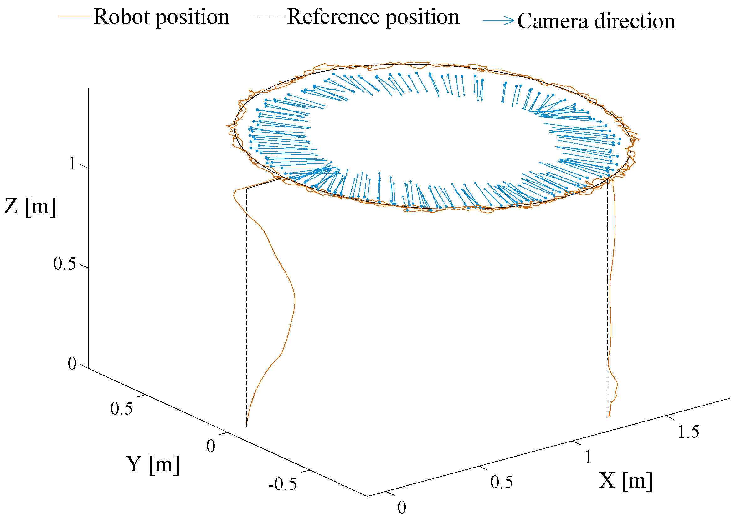
2.4.2. First Trajectory: A Fast 3D Reconstruction Method

The first step in the automated generation of the 3D model reconstruction consisted of taking a circular path around the capital while the embedded Raspberry Pi camera was taking photographs, as shown in Figure 5. The aim of this first trajectory was three-fold: (i) first to determine whether the quality of the photographs taken onboard was good enough for photogrammetric 3D reconstruction purposes; (ii) secondly to obtain a sparse reconstruction of the capital in order to extract information about the object, such as its dimensions, its shape and its exact position in the arena; and (iii) thirdly, to obtain the photographs required for the final dense reconstruction.
The position and angular errors are the differences between the position and angle estimated by MicMac and the absolute ones given by the Vicon ground-truth system. The errors are presented in Table 2. The exterior orientation is provided here by the Vicon ground-truth system. It gives an absolute scale in cm. The absolute position is therefore converted into the MicMac orientation XML file as an initial solution for the MicMac bundle adjustment algorithm. It was indispensable for the robot to be stable and accurate enough to prevent it from colliding with the object targeted. It was also essential to limit the robot’s vibrations so that the images would not be blurred. A constant speed of 2.5 cm·s - 1 and a constant altitude of 1 . 2 m were therefore imposed on the robot in order to ensure homogeneous coverage and high-quality images.
As explained above in Section 2.4.1, a MicMac orientation matching step using data from the motion capture system was necessary to obtain trustworthy information about the capital’s position in the flying arena and its dimensions. The photogrammetric software used in the automatic mode estimated only the cameras’ relative positions (no absolute positions) with a random scale and a random triaxial reference frame. A slight mismatch therefore existed between the camera positions estimated by MicMac and given by the Vicon system. Two solutions to this problem were tested: first, generating the XML orientation files directly from the data collected by Vicon or replacing the XML orientation files given by MicMac by the result of the affine transformation matching the camera relative positions estimated by MicMac with the absolute position given by the Vicon ground-truth system. Although both methods worked satisfactorily, the matching solution was somewhat more accurate and gave much finer results. We therefore opted for the second solution using an Iterative Closest Point (ICP) matching algorithm.
Figure 6 shows the orientation matching between the camera positions determined by MicMac and in the Vicon coordinate system. The ICP algorithm used was mostly inspired by [16]: the final goal was to minimize the difference between two clouds of points.
The ICP algorithm computed the transformation incrementally, combining translations and rotations in order to minimize the mean square error between a reference point cloud, v i (in this case, the camera positions given by Vicon), and a data point cloud, m i (in this case, the camera positions delivered by MicMac). The ICP algorithm we used involves four main stages: (i) for each point in the data point cloud m i , find the nearest neighboring point in the target point cloud v i ; (ii) find the transformation that minimizes the point-to-point mean square error cost function presented in (1); (iii) apply this transformation to the set of data points; and lastly, (iv) iterate the procedure with the new transformed set of points.
E = i = 1 n R m i + T - v i 2
where n is the number of points in the point cloud sets and R and T are the rotation and translation computed by the ICP algorithm at each step.
At the first iteration, we evaluate the homothety between the two point clouds that minimizes the mean square distance required to rescale the MicMac point cloud. Although ICP algorithms are usually used with the nearest neighbor algorithm for matching points, the point matching was constrained here because the points were already properly sorted in both sets. The algorithm was then iterated 50 times.
The positioning errors presented in Table 3 can be explained by:
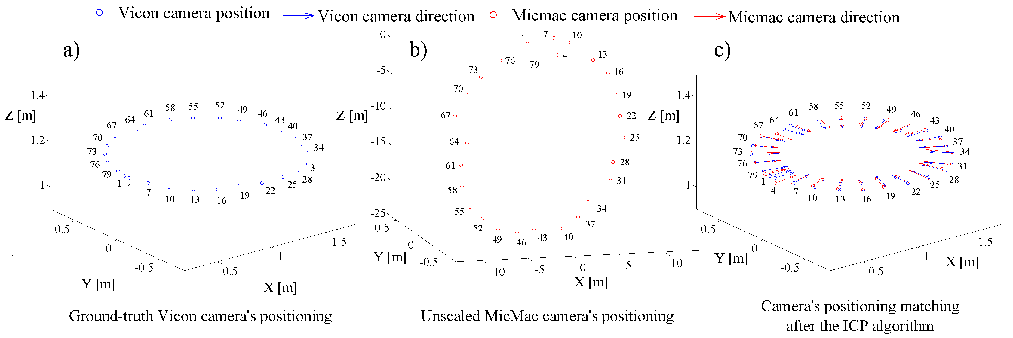
  • errors made by MicMac when calculating the first camera position,
  • lack of synchronization in the camera triggering,
  • errors in the ICP matching algorithm,
  • positioning errors made by Vicon (∼mm).
We were therefore able to match the random spatial representation given by MicMac with the Vicon reference frame. The results obtained in this preliminary task enabled us to extract relevant information about the capital’s exact position and dimensions and to plot true-to-scale 3D point clouds.

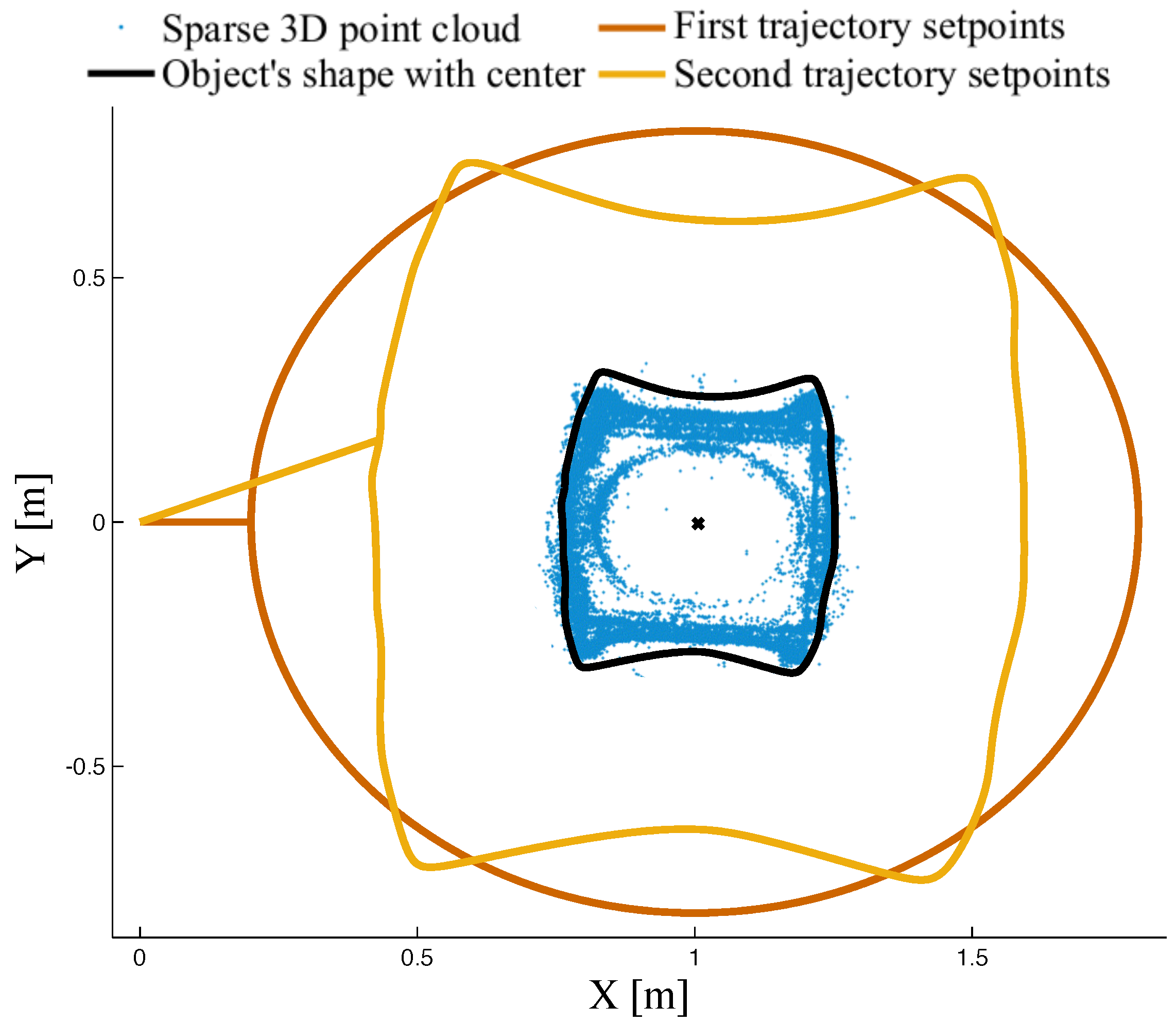
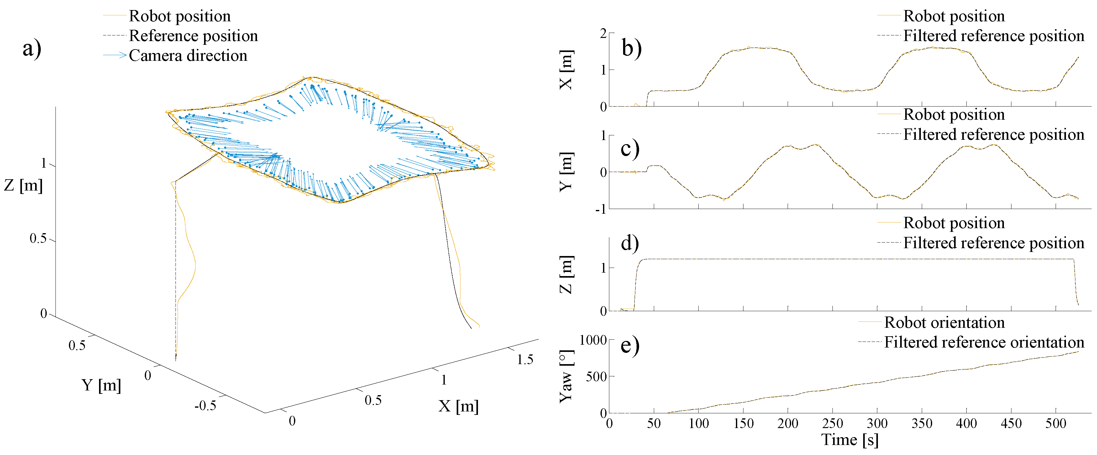
2.4.3. Second Trajectory: Smart Trajectory Depending on the Artifact’s Shape
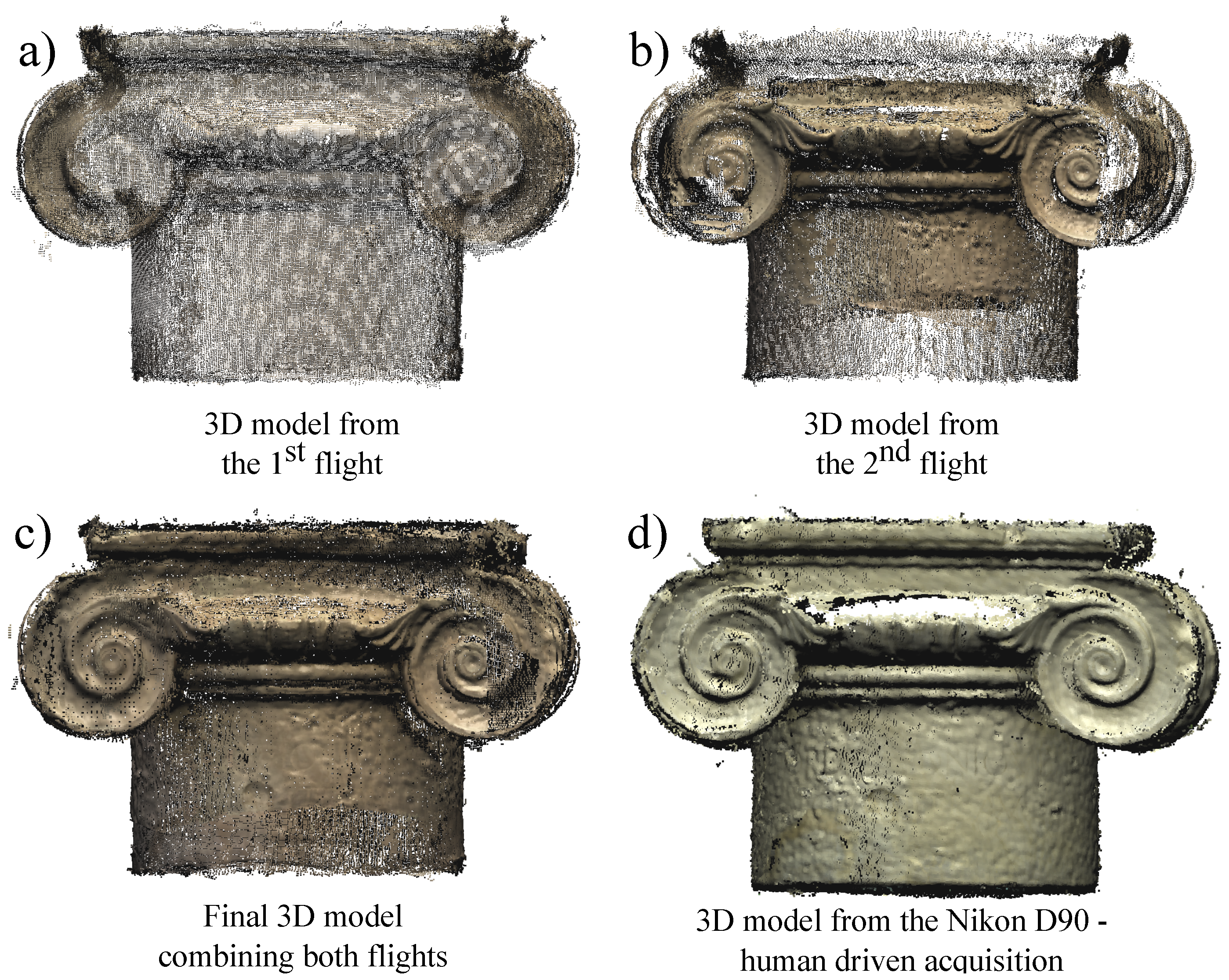
Based on the previous step, we were able to plot a true-to-scale sparse point cloud representing the capital during the first trajectory, which is presented in blue in Figure 7. To improve the dense reconstruction, a second trajectory taking the target object’s morphology closely into account was generated.
The idea here was to extract the shape of the capital in the horizontal plane in order to generate a suitable trajectory. The sparse point cloud previously generated was projected onto the XY plane as indicated in blue in Figure 7. For this purpose, a 2D shape-fitting technique known as α-shape was applied to the sparse point cloud generated during the first trajectory. The α-shape concept, which was first introduced by Edelsbrunner et al. [17], is an extension of the concept of convex hulls. α-shapes depend on a parameter α ranging between 0 and infinity that determines the refinement of the shape of a set of points. A point is α-extreme if there is an empty disk, the radius of which α has this point on its boundary. The α-shape is the straight line graph connecting all of the α-extreme points. In our calculations, the radius used for the α-shape computation is equal to 0.18. Once the α-shape algorithm had been performed, the outline was smoothed with a Bezier curve process, giving the black shape in Figure 7. The shape-induced trajectory is then obtained by homothety, leaving a safety distance of 50 cm from the capital.
The 3D view of the induced fitted trajectory is presented in Figure 8, giving the position and orientation errors shown in Table 4. At this point, the idea is to use the results obtained in the first trajectory and straightforwardly merge them with the second one. First, tie-points for the second dataset are extracted using the same parameters as in the previous step. Both datasets are then linked together using a specific strategy to match all possible pairs of images in between the two flights. Pictures of the rectified trajectory are subsequently integrated into the previously calculated ground-truth orientation system. All of the camera positions occurring during the first flight are frozen, which means that only those occurring during the second trajectory are added to the absolute spatial reference frame. Lastly, the dense matching is computed based on both trajectories, using all 360 images. The algorithm, which is set in the epipolar correlation mode, automatically identifies the best stereographic pairs and computes the dense point cloud. In the present case, the density was set so as to obtain 1 point per 16 pixels, although this ratio could be decreased without any serious loss of accuracy. In order to assess the quality of this 3D reconstruction, it was compared with a non-embedded and non-automated data acquisition device (a Nikon D90 reflex camera), as discussed in the following section.

3. Results

The aim of these experiments was to find a means of acquiring data in situations where classical approaches are not appropriate. The target object, an Ionic column’s capital replica, was chosen because of its complex shape, which could be difficult to handle by a standard 3D digitization process. In the proposed approach, using photography as visual data and thanks to an automated controlled quadrotor, we aim at obtaining a good quality 3D photogrammetric model despite the complex geometry of the target object. In the literature, the standard approach, which implies a quadrotor for remote sensing, consists of 3D model reconstruction with a photogrammetric texture. In [18], a new topography of an archaeological site was produced using drone-derived 3D photogrammetry combined with GPS data. A 3D model with a photogrammetric texture is provided. The purpose of the technique proposed in the present paper consists of precisely reconstructing the CH in order to detect any deterioration and morphological evolution over time. We propose in this innovative work an automated and object-based approach, which takes into account the morphology of the CH by means of an open-source hardware and an open-source software. The automated technique consists of adapting the acquisition protocol. The goal is to precisely reconstruct the CH in order to detect any deterioration and morphological evolution over time. This paper includes a comparison with respect to a manual acquisition using a 12.9-megapixel reflex camera operated by an photographer from the ground. The camera generally used these days in the field of image-based modeling is a DSLR (Digital Single-Lens Reflex) with a CMOS APS-C sensor (such as the Nikon D90 camera used here to obtain the reference data). However, there exists a huge gap of quality and price between a camera of this kind and the Raspberry Pi Camera device, which has a much smaller sensor size, resolution and pixel size (see Table 5). The aim of the device comparison was to set a reasonably comparable framework, simulating a hand-made acquisition with classical equipment from the ground with low-cost robotized equipment and the innovative part of the automation of data acquisition and processing. In the comparison test, the Nikon model has been proportionally subsampled during the dense matching process to fit the maximum density reachable with our method. It clearly highlights the ability of our method to obtain similar results with a DSLR with the difference that we succeed in filling occlusion thanks to an automated two-step shape-adapted trajectory generation.
The raw 3D reconstructions of the capital obtained during the different acquisition steps are shown in Figure 9: those screen-shots depict the improvement thanks to the two-step 3D reconstruction. According to the slightly difference sensor size presented in Table 5, the number of pictures taken with the Raspberry camera is much higher than with the Nikon D90 in order to obtain similar results with the two devices. We observed that in the 3D model presented in Figure 9b,c, some occluded areas were filled in thanks to the data obtained in the second flight, giving a final picture that closely matched the shape of the ionic capital.
The results presented in Table 6 are described in terms of the Ground Sample Distance (GSD), which is the main index used to assess the spatial and metric resolution of an image-based model. The GSD is defined by the relation expressed in (2) between the focal length f, the distance from the object D and the pixel size Px:
f D = P x G S D
The larger the GSD, the lower the spatial resolution of the digital model will be. However, the GSD does not take into account the sensor’s imprecision or image quality (i.e., the noise, pixel interpolation, etc.), which depends mainly on the sensor’s pixel density (the number of pixels with respect to the sensor’s size). We therefore introduced the crop-factor (the ratio between the sensor area and the full-frame reference format) as a multiplier to define the graphical error, and the metric residue therefore expresses this theoretical error multiplied by the average residue in pixels. This explains why the dense matching process had to be subsampled in order to stay below the theoretical maximal graphical error threshold. The final point-cloud from our automated UAV has been achieved with a scale factor of four (i.e., one point for 16 pixels; see Table 6) during the sense matching process and is comparable to the manual DLSR one using the same setting.

4. Discussion

The latest evolution of computer vision algorithms brings photogrammetric solutions in conjunction with commercial UAVs. In [19], three chosen photogrammetric software programs, PhotoScan, Pix4Dmapper and MicMac, are used to analyze different regions of interest in distinct scenery. Errors in geolocation are examined, confirming other recent scientific studies that MicMac is able to achieve the best results in photogrammetric reconstruction. Concerning the robotic platform, the comparison of the use of a low-cost lightweight commercial UAV to the open-source quadrotor in use for our experiments is beyond the scope of this work. In the controlled environment of our study, the low-cost and open-source quadrotor X4-MaG is particularly suited to the automated flights inside the Vicon motion capture system together with an automated and object-based approach, which takes into account the morphology of the CH. Moreover, the use of a very lightweight drone prevents from damages in case of a collision with the CH object. The proposed 3D reconstruction system has some great advantages: (i) it can approach remote areas to determine the overall shape of an architectural object; and (ii) it is able to fill in some large occluded areas, which may occur in the case of manual acquisition, as shown in Figure 9d between the two volutes. The level of uncertainty of the reconstruction naturally increased when a micro-camera embedded in a lightweight quadrotor robot was used. This means that even with an improved image quality and an optimized data processing, the low cost embedded camera is not yet able to reconstitute the finest details of a cultural heritage object: this may be due to the lack stabilization (i.e., UAV flight, vibrations) and the low-cost small sensor camera. Nevertheless, despite these technical issues [20], the result obtained in Figure 9c shows an efficient exploitation of the sensor capacities in terms of the signal/noise ratio. The comparison with the DSLR model proves that we could get a similar result regarding the density, as well as the consistency of the global shape. Hence, this presented system could be an alternative or complementary solution to acquire data when a tricky photogrammetric survey using long focal length (i.e., beyond 100 mm) is too complicated to setup or does not give accurate enough results.
The picture quality is paramount in the field of photogrammetric 3D reconstruction, but the level of performance of the 3D model was limited by the resolution of the sensor used, the vibrations caused by the robot’s flight and the sharpness of the photographs taken in-flight: these factors may mainly explain the differences observed with the 3D model obtained using a reflex camera. The automated MicMac pipeline can be used to process the in-flight images with very little human intervention. All in all, this is the first step towards a fully-automated reconstruction procedure based on the use of a miniature low-cost quadrotor, which is a new powerful tool for close-range photogrammetry in terms of its completeness, accuracy and quickness. During the present experiments, the lighting condition inside the Vicon camera-based motion capture system is fully controlled. For outdoor applications in the presence of shadows coming from buildings or mountains, the 3D reconstruction can be sometimes problematic. CH reconstruction indoors when the lights are inhomogeneous using a quadrotor is also beyond the scope of this work, and it raises some important points, such as colorimetric issues, moving light, shadow, and so on. This paper describes a first attempt at a shape-adapted data acquisition protocol; the current symmetric morphology of our case-study leads us to apply this 2D discrimination protocol (average profile in altitude seems relevant), but could be expanded to more complex objects by an octree-based approach. It was also established here that the present process can be used to reconstruct and scale a 3D model despite the fact that the camera’s position and direction are not exactly known. Possible ways of upgrading this procedure are:
  • to use a miniature camera endowed with an internal stabilizer,
  • to reduce the infrastructure cost by further improving the trade-off between accurate timing synchronization and the need to determine the camera’s position and direction accurately.
From a technical point of view, some improvements have to be performed in terms of hardware and software. In our opinion, (i) the best synchronization of the camera triggering can be obtained using a Linux real-time Kernel running on the Raspberry Pi; and (ii) a low-cost local positioning system [21] might suffice to avoid having to use a costly motion capture system and to obtain a satisfactory trade-off in terms of the quality of the 3D reconstruction. Furthermore, the photogrammetric data processing could integrate some updated features (e.g., tie-points reduction, initial orientation using a trifocal tensor) for a gain of robustness and velocity in the computation stage. This experiment has also to be seen in terms of the applications for the survey and the studies of CH artifacts by filling a gap to digitize remote objects and the ability to monitor their states. Firstly, this kind of system would be valuable help and an efficient solution for the survey of remote objects (e.g., vaults, capitals, pinnacles) where physical access is delicate or impossible. Secondly, as the system provides direct ground truth measurement in an automated process, it could be used for the follow-up of an artifact by giving the opportunity to reproduce a data acquisition to get a comparable dataset at different temporal states. Thus, one step forward could be to focus the development of this prototype to be dedicated to the monitoring issue of CH artifacts by linking this smart and innovative data acquisition device with data processing solutions to assess and quantify the degradation phenomena [22].

5. Conclusions

Thanks to the accurate motion capture system mounted onboard, the small, low-cost quadrotor equipped with a miniature low-resolution Raspberry Pi camera module presented here can deliver photographs of a sufficiently high quality to accurately produce a 3D model of a cultural heritage artifact. Three hundred sixty photographs were taken in-flight every 2 s at a linear speed of 2 . 5 cm·s - 1 to ensure the efficient coverage of the work of art targeted. Despite the small size of the target, a high number of photographs was requested with regards to the small size of the sensor and for safety to prevent from potential motion blur in the acquired image in flight. In the future, we endeavor the implementation of an additional camera to create a stereo pair to make the dense matching process even better. The robot was accurately piloted in the flying arena using a ground-truth Vicon system with which a closed-loop control system was implemented. The image set acquired during the first circular flight gave the artifact’s 2D shape. The second trajectory was smartly generated, using this artifact’s 2D shape to detect the details of the artifact’s surface more closely during the second flight. The automated miniature flying camera succeeded in following the newly-defined trajectory and building a more detailed picture of the artifact while keeping a safe distance from it. The automatic generation of the second trajectory could also be pursued by a third one using finer approaches based on voxels and/or octree quantification until occlusion will be totally filled by the integration of a next-best view planning algorithm [23]. The quality of the final 3D reconstruction based on the two combined image sets was encouraging in comparison with the 3D model obtained with a manually-operated and heavy reflex camera; moreover, this first result still could be slightly improved adding a second camera to create a rigid block stereo pair system to help the dense matching process. No benchmarking has been done, but the automated acquisition and processing allow one to save time that could be used to repeat the experiments and to multiply the 3D digitization campaign. The improved efficiency of close-range photogrammetric methods in terms of their completeness, accuracy and quickness should lead to the development of flexible frameworks for using these new surveying techniques to transmit knowledge around the world. The complete automation of the whole 3D digitization pipeline will soon make it possible to create huge collections of digital models, and the future development of reproducible processes will no doubt open new paths for monitoring the aging of CH artifacts.

Supplementary Materials

The following are available online at www.mdpi.com/2072-4292/8/10/858/s1, Video S1: A shape-adjusted 3D reconstruction of CH artifacts using a miniature quadrotor.

Acknowledgments

We are most grateful to Marc Boyron and Julien Diperi for their involvement in the electronic and mechanical design of the sensors and the robot. We also thank Fabien Colonnier for his assistance and helpful advice and J. Blanc for correcting and improving the English manuscript. This work was supported by CNRS Institutes (Life Science; Information Science; Engineering Science and Technology; and Humanities and Social Science), Aix-Marseille University and French Ministry of Culture and Communication (MCC).

Author Contributions

Théo Louiset performed all of the experiments, analyzed the data and contributed to manuscript writing. Anthony Pamart and Eloi Gattet analyzed the data, advised on the final 3D reconstruction of the cultural heritage artifact using the free open-source MicMac-Apero toolchain, as well as contributed to manuscript writing. Thibaut Raharijaona contributed to implementing the control laws onboard the autonomous quadrotor, to guide the experiments and to manuscript writing. Livio De Luca and Franck Ruffier conceived of the study, analyzed the data, guided the experiments and contributed to manuscript writing.

Conflicts of Interest

The authors declare no conflict of interest.

Abbreviations

The following abbreviations are used in this manuscript:
APS-CAdvanced Photo System Type-C
CHCultural Heritage
CMOSComplementary Metal Oxide Semiconductor
DSLRDigital Single Lens Reflex
FTPFile Transfer Protocol
GSDGround Sample Distance
ICPIterative Closest Point
IMUInertial Measurement Unit
SIFTScale-Invariant Feature Transform
UARTUniversal Asynchronous Receiver Transmitter
UAVUnmanned Aerial Vehicle

References

  1. Levoy, M.; Pulli, K.; Curless, B.; Rusinkiewicz, S.; Koller, D.; Pereira, L.; Ginzton, M.; Anderson, S.; Davis, J.; Ginsberg, J.; et al. The Digital Michelangelo Project: 3D scanning of large statues. In Proceedings of the 27th Annual Conference on Computer Graphics and Interactive Techniques, SIGGRAPH ’00, New Orleans, LA, USA, 23–28 July 2000; pp. 131–144.
  2. Stanco, F.; Battiato, S.; Gallo, G. Digital Imaging for Cultural Heritage Preservation: Analysis, Restoration, and Reconstruction of Ancient Artworks, 1st ed.; CRC Press, Inc.: Boca Raton, FL, USA, 2011. [Google Scholar]
  3. Callieri, M.; Scopigno, R.; Sonnino, E. Using 3D digital technologies in the restoration of the Madonna of Pietranico. ERCIM News, October 2011; 48. [Google Scholar]
  4. Santos, P.; Ritz, M.; Tausch, R.; Schmedt, H.; Monroy, R.; Stefano, A.D.; Posniak, O.; Fuhrmann, C.; Fellner, D.W. CultLab3D—On the verge of 3D mass digitization. In Proceedings of the Eurographics Workshop on Graphics and Cultural Heritage, The Eurographics Association, Aire-la-Ville, Switzerland, 6–8 October 2014; pp. 65–74.
  5. Gattet, E.; Devogelaere, J.; Raffin, R.; Bergerot, L.; Daniel, M.; Jockey, P.; De Luca, L. A versatile and low-cost 3D acquisition and processing pipeline for collecting mass of archaeological findings on the field. Int. Arch. Photogramm. Remote Sens. Spat. Inf. Sci. 2015, XL-5/W4, 299–305. [Google Scholar] [CrossRef]
  6. Pierrot-Deseilligny, M.; De Luca, L.; Remondino, F. Automated image-based procedures for accurate artifacts 3D modeling and orthoimage generation. Geoinform. FCE CTU 2011, 6, 291–299. [Google Scholar] [CrossRef]
  7. Toschi, I.; Capra, A.; De Luca, L.; Beraldin, J.A.; Cournoyer, L. On the evaluation of photogrammetric methods for dense 3D surface reconstruction in a metrological context. ISPRS Ann. Photogramm. Remote Sens. Spat. Inf. Sci. 2014, 2, 371–378. [Google Scholar] [CrossRef]
  8. Rosu, A.M.; Assenbaum, M.; De la Torre, Y.; Pierrot-Deseilligny, M. Coastal digital surface model on low contrast images. Int. Arch. Photogramm. Remote Sens. Spat. Inf. Sci. 2015, 40, 307–312. [Google Scholar] [CrossRef]
  9. Kriegel, S.; Rink, C.; Bodenmüller, T.; Narr, A.; Suppa, M.; Hirzinger, G. Next-best-scan Planning for autonomous 3D modeling. In Proceedings of the 2012 IEEE/RSJ International Conference on Intelligent Robots and Systems (IROS), Vilamoura-Algarve, Portugal, 7–11 October 2012; pp. 2850–2856.
  10. Saleri, R.; Pierrot-Deseilligny, M.; Bardiere, E.; Cappellini, V.; Nony, N.; Luca, L.D.; Campi, M. UAV photogrammetry for archaeological survey: The Theaters area of Pompeii. In Proceedings of the Digital Heritage International Congress (DigitalHeritage), Marseille, France, 28 October–1 November 2013; Volume 2, pp. 497–502.
  11. Michael, N.; Mellinger, D.; Lindsey, Q.; Kumar, V. The grasp multiple micro-UAV testbed. IEEE Robot. Autom. Mag. 2010, 17, 56–65. [Google Scholar] [CrossRef]
  12. Lupashin, S.; Hehn, M.; Mueller, M.W.; Schoellig, A.P.; Sherback, M.; D’Andrea, R. A platform for aerial robotics research and demonstration: The Flying Machine Arena. Mechatronics 2014, 24, 41–54. [Google Scholar] [CrossRef]
  13. Manecy, A.; Marchand, N.; Ruffier, F.; Viollet, S. X4-MaG: A low-cost open-source micro-quadrotor and its Linux-based controller. Int. J. Micro Air Veh. 2015, 7, 89–110. [Google Scholar] [CrossRef]
  14. Manecy, A.; Marchand, N.; Viollet, S. RT-MaG: An open-source SIMULINK Toolbox for Real-Time Robotic Applications. In Proceedings of the IEEE International Conference on Robotics and Biomimetics, Bali, Indonesia, 5–10 December 2014.
  15. Fraser, C.S. Digital camera self-calibration. ISPRS J. Photogramm. Remote Sens. 1997, 52, 149–159. [Google Scholar] [CrossRef]
  16. Kjer, H.M.; Wilm, J. Evaluation of Surface Registration Algorithms for PET Motion Correction. Ph.D. Thesis, Technical University of Denmark (DTU), Kongens Lyngby, Denmark, 2010. [Google Scholar]
  17. Edelsbrunner, H.; Kirkpatrick, D.; Seidel, R. On the shape of a set of points in the plane. IEEE Trans. Inf. Theory 1983, 29, 551–559. [Google Scholar] [CrossRef]
  18. Margottini, C.; Fidolini, F.; Iadanza, C.; Trigila, A.; Ubelmann, Y. The conservation of the Shahr-e-Zohak archaeological site (central Afghanistan): Geomorphological processes and ecosystem-based mitigation. Geomorphology 2015, 239, 73–90. [Google Scholar] [CrossRef]
  19. Moutinho, O.F.G. Evaluation of Photogrammetric Solutions for RPAS: Commercial vs. Open Source. Master’s Thesis, University of Porto, Porto, Portugal, 2015. [Google Scholar]
  20. Aber, J.S.; Marzolff, I.; Ries, J. Small-Format Aerial Photography: Principles, Techniques and Geoscience Applications; Elsevier: Amsterdam, The Netherlands; Oxford, UK, 2010. [Google Scholar]
  21. Raharijaona, T.; Mignon, P.; Juston, R.; Kerhuel, L.; Viollet, S. HyperCube: A small lensless position sensing device for the tracking of flickering infrared LEDs. Sensors 2015, 15, 16484–16502. [Google Scholar] [CrossRef] [PubMed]
  22. Peteler, F.; Gattet, E.; Bromblet, P.; Guillon, O.; Vallet, J.M.; De Luca, L. Analyzing the evolution of deterioration patterns: A first step of an image-based approach for comparing multitemporal data sets. In Proceedings of the 2015 Digital Heritage, Granada, Spain, 28 September–2 October 2015; Volume 2, pp. 113–116.
  23. Dellepiane, M.; Cavarretta, E.; Cignoni, P.; Scopigno, R. Assisted multi-view stereo reconstruction. In Proceedings of the 2013 International Conference on 3D Vision-3DV 2013, Seattle, WA, USA, 29 June–1 July 2013; pp. 318–325.
Figure 1. (a) The X4-MaG quadrotor equipped with an embedded Raspberry Camera weighs 367 grams and can fly autonomously for 10 min. It can fly closer to the artifact (here, a capital) to capture more details without endangering the artifact itself because of its small size and low weight. (b) The flying test arena in Marseilles with its 17 Vicon cameras can be used to control the quadrotor’s trajectory around the artifact. The ground-truth Vicon system provides the position of the quadrotor used for monitoring purposes, which is necessary to control in a closed loop.
Remotesensing 08 00858 g001
Figure 2. The X4-MaG robot is fully controlled via the Linux-based controller embedded onboard the Gumstix Overo. The image acquisition is performed with an Odroid W board and its small 5-Mpx Raspberry Camera Module.
Remotesensing 08 00858 g002
Figure 3. Interconnection between the various systems. The first ground station (PC 1) equipped with MATLAB/Simulink receives orientation and position data from the Vicon motion tracking system. PC 1 is connected to the Gumstix Overo via a WiFi connection and sends setpoints and parameters to the Gumstix high level autopilot via the MATLAB/Simulink toolbox. All of the attitude and position control processes are computed in real time onboard the aerial robot. The second ground station (PC 2) equipped with MicMac is connected to the Odroid W via a second WiFi connection. The Odroid communicates with the Gumstix via a serial connection (UART), which makes it possible to determine the camera’s position whenever a picture is taken. Pictures are sent directly to PC 2 via WiFi (FTP). The two PCs communicate via the local Ethernet network.
Remotesensing 08 00858 g003
Figure 4. Global overview of the final dense point cloud generation. First a picture of the highly overlapping data acquisition based on 180 photographs was obtained during a circular trajectory. Inputs consisting of the photographs, the camera’s positions and the internal calibration were delivered to the MicMac for processing. MicMac first generated a sparse point cloud, which was used to generate the second trajectory. Further calculations in MicMac’s epipolar dense matching mode resulted in the generation of a dense point cloud. Lastly, the two dense point clouds were combined, giving the final reconstruction.
Remotesensing 08 00858 g004
Figure 5. 3D view of the first circular trajectory, giving the camera’s direction and the robot’s position ( v = 2 . 5 cm·s - 1 ).
Remotesensing 08 00858 g005
Figure 6. Orientation matching between the camera positions estimated by MicMac and given by the Vicon system. The numbers above each point correspond to the picture numbering code. (a) The camera positions when a picture was taken in the Vicon coordinate system; (b) the camera positions when a picture was taken in the MicMac coordinate system; (c) camera positions and orientations once the ICP algorithm had been computed.
Remotesensing 08 00858 g006
Figure 7. In black, the capital’s shape and its center as computed by the α-shape algorithm [17]. In blue, top view of the sparse 3D point cloud generated on the basis of the photographs taken during the first trajectory. The first and second trajectory’s position setpoints are also shown. The second trajectory was determined by dilating the 2D capital’s shape with a safety distance of 50 cm.
Remotesensing 08 00858 g007
Figure 8. On the left (a), a 3D view of the second trajectory gives the camera’s direction and the robot’s position ( v = 2 . 5 cm·s - 1 ). On the right (be), the positions X, Y, Z and the angle Ψ (yaw) versus time are plotted.
Remotesensing 08 00858 g008
Figure 9. Raw 3D reconstructions of the capital obtained with two image acquisition procedures using a Raspberry Pi camera module in (ac) and the Nikon D90 in (d). The raw 3D model based on the 180 in-flight pictures taken during the first flight is shown in (a), and that based on the 180 in-flight pictures taken during the second flight is shown in (b). The 360 pictures of both flights were combined and merged, giving the final 3D reconstruction presented in (c). The results of manual acquisition based on the heavy reflex Nikon D90 (shown in (d)) were used as the main reference in the comparisons between procedures. Those screen-shots depict the improvement of the two-step reconstruction. One shall notice the similar density and accuracy with the heavy DSRL (Digital Single-Lens Reflex) manual acquisition, but a large occlusion area was present between the two volutes in the case of this manual acquisition. Moreover in (c), the reconstruction based on two aerial trajectory acquisitions filled this occlusion area, and the final 3D model does not show any large occlusion.
Remotesensing 08 00858 g009
Table 1. Specifications of the camera module.
Specifications
Mass (g)3
Resolution (Mpx)5
Field of view ( ) 53 . 50 ± 0 . 13 × 41 . 41 ± 0 . 11
Image Sensor area (mm 2 ) 3 . 76 × 2 . 74
Pixel size ( μ m 2 ) 1 . 74 × 1 . 74
Signal to Noise Ratio (SNR) (dB)36
Table 2. The standard deviation, maximum absolute error and mean absolute error of the first circular trajectory.
Mean ErrorMax ErrorStandard Deviation
X (cm) 1 . 42 7 . 57 1 . 82
Y (cm) 1 . 26 6 . 01 1 . 62
Z (cm) 0 . 09 1 . 06 0 . 13
Global (cm) 1 . 89 11 . 32 1 . 61
Ψ ( ) 1 . 69 10 . 7 2 . 21
Table 3. Mismatch Errors between camera position/direction determined by Micmac and the Vicon system.
Mean ErrorMax ErrorStandard Deviation
Camera position (cm) 2 . 5 8 . 3 1 . 4
Camera direction ( ) 3 . 2 9 . 2 1 . 6
Table 4. The standard deviation, maximum absolute error and mean absolute error of the second induced trajectory.
Mean ErrorMax ErrorStandard Deviation
X (cm) 1 . 39 5 . 59 1 . 78
Y (cm) 1 . 05 6 . 14 1 . 39
Z (cm) 0 . 07 0 . 89 0 . 10
Global (cm) 1 . 71 7 . 68 1 . 38
Ψ 1 . 61 7 . 23 2 . 07
Table 5. Parameters of the camera devices.
Automated Quadrotor Embedded Raspberry Pi CameraManual Reflex Nikon D90 Operated by a Photographer
Sensor size (mm 2 )3.76 × 2.7423.6 × 15.8
Resolution (megapixels)512.9
Image resolution (pixels)2592 × 19444288 × 2848
Pixel-size (μ m)1.45.5
Focal length (mm)3.638
35-mm equivalent focal length3658
Table 6. Metric comparison between the reconstructed 3D models.
Automated Quadrotor Embedded Raspberry Pi CameraManual Reflex Nikon D90 Operated by a Photographer
Distance (m)0.71.2
GSD (mm)0.270.16
Graphical Error (mm)2.70.24
CalibTraj1Traj1 + Traj2
Residue (px)0.372.222.771.22
Number of pictures1118036037
Metric residue (mm·px - 1 )7.40.3
Subsampling (px/line)88
Point-cloud GSD (mm)2.161.28
Number of points34,000348,000

