Calibrate Multiple Consumer RGB-D Cameras for Low-Cost and Efficient 3D Indoor Mapping
by
 , ,
, ,
Chi Chen
1,2,3,*, 
Bisheng Yang
1,2,*,
Shuang Song
1,2,
Mao Tian
1,2,
Jianping Li
1,2,
Wenxia Dai
1,2 and
Lina Fang
3 1
State Key Laboratory of Information Engineering in Surveying, Mapping and Remote Sensing, Wuhan University, Wuhan 430079, China
2
Engineering Research Center for Spatio-Temporal Data Smart Acquisition and Application, Ministry of Education of China, Wuhan University, Wuhan 430079, China
3
Key Laboratory of Spatial Data Mining & Information Sharing of Ministry of Education, Fuzhou University, Fuzhou 350000, China
*
Authors to whom correspondence should be addressed.
Remote Sens. 2018, 10(2), 328; https://doi.org/10.3390/rs10020328
Submission received: 20 November 2017
/
Revised: 12 February 2018
/
Accepted: 16 February 2018
/
Published: 22 February 2018
Abstract
:Traditional indoor laser scanning trolley/backpacks with multi-laser scanner, panorama cameras, and an inertial measurement unit (IMU) installed are a popular solution to the 3D indoor mapping problem. However, the cost of those mapping suits is quite expensive, and can hardly be replicated by consumer electronic components. The consumer RGB-Depth (RGB-D) camera (e.g., Kinect V2) is a low-cost option for gathering 3D point clouds. However, because of the narrow field of view (FOV), its collection efficiency and data coverages are lower than that of laser scanners. Additionally, the limited FOV leads to an increase of the scanning workload, data processing burden, and risk of visual odometry (VO)/simultaneous localization and mapping (SLAM) failure. To find an efficient and low-cost way to collect 3D point clouds data with auxiliary information (i.e., color) for indoor mapping, in this paper we present a prototype indoor mapping solution that is built upon the calibration of multiple RGB-D sensors to construct an array with large FOV. Three time-of-flight (ToF)-based Kinect V2 RGB-D cameras are mounted on a rig with different view directions in order to form a large field of view. The three RGB-D data streams are synchronized and gathered by the OpenKinect driver. The intrinsic calibration that involves the geometry and depth calibration of single RGB-D cameras are solved by homography-based method and ray correction followed by range biases correction based on pixel-wise spline line functions, respectively. The extrinsic calibration is achieved through a coarse-to-fine scheme that solves the initial exterior orientation parameters (EoPs) from sparse control markers and further refines the initial value by an iterative closest point (ICP) variant minimizing the distance between the RGB-D point clouds and the referenced laser point clouds. The effectiveness and accuracy of the proposed prototype and calibration method are evaluated by comparing the point clouds derived from the prototype with ground truth data collected by a terrestrial laser scanner (TLS). The overall analysis of the results shows that the proposed method achieves the seamless integration of multiple point clouds from three Kinect V2 cameras collected at 30 frames per second, resulting in low-cost, efficient, and high-coverage 3D color point cloud collection for indoor mapping applications.

1. Introduction
Driven by the miniaturization and light weight of positioning and remote sensing sensors, as well as the need of fusing indoor and outdoor maps for next-generation navigation, 3D indoor mapping from mobile laser scanning is a hot research and application topic. Point clouds with auxiliary information such as color and infrared images derived from 3D indoor mobile mapping suites can be used in a variety of novel applications, including indoor scene visualization [1], automated floor plan generation [2], gaming, reverse engineering, navigation [3], and simulation [4]. State-of-the-art 3D indoor mapping systems equipped with multiple laser scanners produce accurate point clouds of building interiors containing billions of points [5]. However, these laser scanner-based systems are expensive. Low-cost consumer RGB-Depth (RGB-D) cameras provide an alternative way to solve the core challenge of indoor mapping, which is capturing the detailed underlying geometry of building interiors. Since PrimeSense and Microsoft launched the first consumer-class RGB-D camera (the Kinect V1) in 2010, low-cost consumer RGB-D cameras have gradually come into public view. According to their measurement principle, RGB-D cameras can be divided into two categories: structured-light (SL)-based and time-of-flight (ToF)-based. Structured light range sensing is an active stereo-vision technique in which a sequence of known patterns is sequentially projected onto the scene, and the distortion (disparity) of the pattern observed by a camera is analyzed to extract the depth information [6]. The ToF approach is based on measuring the time that light emitted by an illumination unit requires to travel to an object and back to the sensor array [7]. The Kinect V1 and Kinect V2 developed by Microsoft are the representative models of the SL-based and ToF-based RGB-D cameras, respectively. At present, there are many indoor 3D mapping studies using both kinds of Kinect sensors [8,9,10,11].
Nevertheless, single RGB-D cameras have a very limited field of view (e.g., Kinect V2 horizontal FOV = 70°) when compared with laser scanners (e.g., typical horizontal FOV = 360°), resulting in low efficiency in data collection and incomplete datasets that miss major building structures (e.g., ceilings, walls) [12]. An existing public benchmark dataset [13] collected by a single RGB-D camera has depicted the missing data defects. Due to the limited budget, low-cost 3D indoor mapping systems built on RGB-D cameras are often not equipped with active position and orientation measurement sensors such as inertial measurement units (IMUs). Visual odometry (VO) and simultaneous localization and mapping (SLAM) algorithms [14,15,16,17] are often used as substitution of those sensors. Similar to the IMU, position and orientation drifts are inevitable and will increase when the VO/SLAM algorithms are applied overtime [18]. Meanwhile, VO/SLAM algorithms do not work properly in no-texture regions or regions with repetitive textures, which are quite common in indoor environments. In general, the scan matching procedures (e.g., iterative closest point, ICP) of a single RGB-D 3D indoor mapping system will fail when the scene lacks features in the available field of view (e.g., only a single homogenous wall is in the view) [10]. For a single RGB-D camera with limited field of view, it is necessary to rotate the RGB-D camera frequently in order to obtain complete coverage of the indoor environment to be measured. This unstable data acquisition mode increases the number of unknown position and orientation parameters that need to be solved, and takes extra time and human labor to achieve full-coverage datasets. Thus, the complexity and accumulation of errors during the VO/SLAM process are increased, and the system robustness is reduced. In all, endeavoring to collect a complete scene without data blanks using a single RGB-D camera in a “rotate-camera” manner is not technically sound. Because the large amount of human labor and sensor position and orientation parameters need to be solved, it will greatly increase the scanning workload, data processing burden, and risk of VO/SLAM failure. VO/SLAM algorithm benefit from a large field of view [19]. Constructing a camera array by combining multiple cameras can help to cope with occlusions and dynamics of the scenes, especially in indoor scenes where spaces are normally tight [20].
Thus, to find an efficient and low-cost way to collect 3D point cloud data with auxiliary information (i.e., color) for indoor mapping, in this paper we present an RGB-D camera array prototype for indoor mapping that is built upon a novel calibration method that solves intrinsic and extrinsic parameters of the individual camera in the array. Three Kinect V2 cameras are mounted on a rig with different view direction to form a large FOV, while the three individual RGB-D data streams are synchronized and gathered by the open source driver OpenKinect [21]. The calibration procedure is two-fold: (1) Intrinsic calibration involving the geometry/depth calibration of a single RGB-D camera; and (2) Extrinsic calibration solving the placement parameters between the RGB-D cameras. Geometry-related intrinsic parameters of the RGB/infrared (IR) cameras in the array are solved by a homography-based method. The depth calibration process first corrects the default IR camera model to the intrinsic calibrated solution and secondly solves the range bias of the ToF sensor by pixel-wise spline line functions. The extrinsic calibration is achieved through a coarse-to-fine scheme that solves the initial placement parameters based on sparse control markers and further refines the initial value by an iterative closest point (ICP) variant minimizing the distance between the RGB-D point clouds and the referenced laser point clouds.
The main contribution of the proposed RGB-D camera array is that it overcomes the shortcomings of the limited view of single RGB-D camera indoor mapping systems by constructing and calibrating RGB-D camera arrays to extend the view of single RGB-D camera, resulting in the high-coverage and efficient collection of a 3D indoor point cloud with auxiliary information.
The rest of the paper is organized as follows: following the introduction, related works are reviewed in Section 2. Section 3 elaborates the system setup of the RGB-D camera array and the proposed calibration method. Experimental studies on the array calibration and 3D indoor mapping results utilizing the proposed indoor mapping prototype are presented and analyzed in Section 4. The pros and cons of the proposed prototype RGB-D cameras array and the calibration method are discussed in Section 5, and conclusions are drawn in the final Section 6.
2. Related Works
Studies of 3D indoor mapping using RGB-D sensors are involved in a broad range of research topics, including RGB-D sensor calibration, RGB-D SLAM systems, and 3D reconstruction from RGB-D point clouds. Most of the existing RGB-D-based indoor mapping studies so far have utilized a single sensor for the gathering of point clouds. The well-known KinectFusion [22,23] achieves real-time dense surface mapping and tracking with a single moving Kinect sensor in small-scale scenes. For large-scale scenes, Kinfu system [24] uses volume shifting and volume slice extraction to adapt KinectFusion to the reconstruction. Other RGB-D SLAM systems use sparse features extracted from RGB images jointly with an ICP algorithm [25], such as Kintinuous [16], RTAB-Map [26], or RGB-D mapping [27]. Only one RGB-D data stream is used as the input to solve the localization and mapping problem in those studies. State-of-the-art indoor mapping studies have solved the RGB-D SLAM in areas rich in texture and geometry information. However, texture-less regions, repetitive geometrical structures, and occlusions are very common in indoor environments. For a single RGB-D SLAM system with a very limited FOV of around 60°, the SLAM algorithms fail in cases when the amount of the features observed in the scene is not enough to solve the location ambiguity, resulting in losses of algorithm robustness. In addition, using single RGB-D sensors whose FOV is small and limited to collect the indoor point clouds often leads to incomplete datasets, such as missing floors or ceilings, which is quite common in the publically-available RGB-D benchmark datasets (e.g., SUN3D [13]).
Extending the FOV of the RGB-D sensor by combining multiple sensors is the intuition to solve this issue. Few studies have been done on combining multiple RGB-D sensors for indoor mapping. Chow et al. proposed a mobile mapping system called Scannect which is the integration of a 3D terrestrial light detection and ranging (LiDAR) system, a micro-electro-mechanical systems (MEMS) IMU, and two Microsoft Kinects mounted on the side of the Scannect to map the indoor environments [10]. Song et al. proposed a rotated top-bottom (RTB) arrangement of two Kinect V1 s to maximize the FOV and adjusted the individual depths to a frontal reference coordinate [28]. Tsai et al. aligned multiple point clouds collected by a structured light RGB-D camera (ASUS Xtion Pro RGB-D camera) mounted on a pan-tilt platform to reconstruct the indoor scenes [29]. An offline extrinsic calibration utilizing checkerboard and online local registration method (e.g., ICP) were combined to register the point clouds collected at every preset pan-tilt control point in their study. Serafin et al. presented an extension to the well-known ICP by using an extended point representation that captures the surface characteristics around the points [30]. Sufficient overlap between depth maps/point clouds should be maintained in those approaches to guarantee the convergence of the ICP algorithm. Matterport3D marketed an RGB-D scanner consisting of three RGB-D sensors pointing in three different directions for indoor modeling and virtual reality applications [31]. The sensor calibration is the basis of and the key to constructing an RGB-D sensor array. This paper thus primarily focuses on the calibration of multiple RGB-D sensors.
The intrinsic calibration of single RGB-D sensors solves the camera geometry and the depth correction. Most of the consumer RGB-D sensors (namely the Kinect and Intel RealSense) are originally designed for human–machine interaction in applications such as gaming, where metric measurements are not the focus. Thus, consumer RGB-D sensors need to be calibrated individually to refine the manufacturer’s batch calibration parameters [10]. RGB-D sensors are a new kind of sensor. Fewer studies have been done on their intrinsic calibration [32,33,34], compared to the mature camera calibration research. The main reason is that the measurements derived from SL/ToF based RGB-D cameras are distorted by several phenomena. Considering especially the ToF based KinectV2 used in this paper, the analysis of related error sources is reported in existing surveys [35,36]. The IR and color optical sensors inside the Kinect V2 could be modeled using the pinhole camera model and solved by well-established RGB camera calibration methods [9,34,37]. The calibration of the relative pose parameters between the IR and RGB cameras is similar to stereo-camera calibration that could be solved by measuring geometrical targets in the shared FOV (e.g., 2D planar pattern [38,39], circle grid [40], 1D target [41,42]), appearance-based methods [43], or self-calibration used in robot navigation [44,45,46]. For depth calibration, additional depth error models based on 3D look-up tables [47,48] interpolating the related deviations, or on curve approximation with single/multiple B-splines [49,50] or polynomials [49] to model the distance deviations have been designed to enhance the quality of depth data.
The extrinsic calibration of multiple RGB-D sensors calculates the relative rotation (boresight) and translation (lever-arm) between individual sensors. In the context of the extrinsic calibration of multiple RGB-D sensors, existing methods can be classified into three categories: (1) moving calibration targets-based; (2) shared view-based; and (3) camera tracking-based methods. The method based on moving calibration targets solves the exterior orientation parameters (EoPs) of each sensor in the array by moving calibration targets with known trajectory across the view of individual sensors. The trajectory of the calibration target is provided by external optical tracking systems. Beck and Froehlich [51] employ a tracked checkerboard to establish correspondences in RGB-D camera space and the world coordinate defined by the tracking system to register multiple RGB-D sensors into a joint coordinate system. Avetisyan et al. [52] calibrated an array of multiple stationary color and depth cameras using an optical tracking system tracking a checkerboard target with four additional markers attached. The use of an optical tracking system in those methods limits their application scope to where a tracking device is already available (e.g., 3D telepresence systems). The shared view-based method solves the extrinsic camera calibration by the detection and matching of control points in the overlapping regions of different cameras. OmniKinect [53] obtains the extrinsic parameters using a calibration target with Kinect-visible markers that are simultaneously detected in the view of the mounted Kinects. Fernández-Moral et al. [54] use an overlap of features in the surrounding planar environment (e.g., walls, ceiling) for the extrinsic calibration of the range camera. However, these methods have the disadvantage that the overlap field of view constraint must be fulfilled. Besides, it is more complicated to match features in depth images than in RGB images. The multiple camera calibration approaches in this category are inappropriate for camera arrays designed with barely or not overlapping field of view like the one proposed in this paper. Camera tracking-based methods do not require an optical tracking system or a sufficient overlap in field of view. They rely on the portability of the cameras and track the ego-motion of the cameras independently. SLAM or VO techniques are applied to determine the extrinsic parameters of multiple generic cameras [55,56]. The final calibration results are correlated to the robustness and accuracy of the used SLAM/VO algorithm, which depends highly on the environment. For indoor scenes filled with texture-less regions or repetitive geometry, this kind of approach is not the optimal choice.
3. Methodology
The proposed RGB-D camera array aims to collect 3D point cloud data with auxiliary information (i.e., color) for indoor mapping in an efficient and low-cost manner. The RGB-D camera array is built upon multiple Kinect V2 cameras, and the calibration method solves intrinsic and extrinsic parameters of each Kinect V2 in the array. Two key components are encompassed in the proposed calibration process: (1) Calibrating the RGB/IR camera geometry of each RGB-D camera by a homography-based method using checkerboard, correcting the infrared ray to obtain the calibrated range-to-3D transformation, and modeling range biases with pixel-wise spline line functions to correct the wiggling error along the range measurement by capturing a planar scene (e.g., a wall) from different depths; (2) Solving the initial EoPs of each RGB-D camera from sparse control markers and further refining the initial value by an ICP variant minimizing the distance between the RGB-D point clouds and the referenced laser point clouds. Figure 1 illustrates the RGB-D camera array setup and the framework of the proposed calibration method. The key components of the sensor array and calibration method are described below.
3.1. RGB-D Camera Array System Setup
There are three types of RGB-D camera, including stereo camera, structured light (SL) camera, and time-of-flight (ToF) camera, distinguished by the measurement principle. The stereo camera and structured light camera use parallax theory to calculate depth, while the ToF camera is based on a beam distance measurement principle, calculating the distance from the travel time of a modulated beam between sensor and object. Among the mainstream ToF camera models, including Microsoft Kinect V2 [57], CubeEye [58], SwissRanger SR4000 [58], and PMD CamCube [59], the Kinect V2 is selected as the sensor array component in this paper for its wider FOV, higher resolution, longer ranging [35], and easier accessibility.
In contrast to the open spaces of outdoor environments, indoor data collections are often impeded by confined and small spaces; therefore, both horizontal and vertical rotation and translation of the camera is required to achieve full data coverage, which leads to a higher risk of feature tracking failure in VO/SLAM algorithms and more data collection/processing workload. Typical indoor environments consist of orthogonal walls and ceilings which follow the Manhattan World Assumption [60]. According to the “Manhattan World” characteristics of the indoor environment, we proposed to mount the sensors vertically with different pitching angles that orient the sensors forward, obliquely upward and downward, as shown in the Figure 1. The pitch angles of the three Kinect V2 sensors were designed to be −50°, 0° and 50°. The roll angles of the sensors were design to be kept consistent at 0°. There was 10° overlap in the FOV of the adjacent sensors. The RGB-D array could theoretically provide 160° × 70° FOV. According to this design, there will be 89% vertical coverage of the scene in front of the array, which is considered adequate for most indoor environments. The coverage is 2.7 times that using a single RGB-D camera (33% coverage).
All sensors were locked on a tripod bar using a ball head, and connected to a mobile work station through a USB3.0 interface. Every sensor was allocated 5 Gbps bandwidth with a USB3.0 expansion card plugged in separate PCI-E slots; the connection is shown in Figure 2. Since the official software development kit (SDK) for Kinect V2 does not support more than one sensor, the open source drive OpenKinect [21] was used to power the three Kinect v2s to collect RGB-D data streams simultaneously. Although the Kinect V2 can obtain depth values for distances between 4.5 m to 9 m using the OpenKinect driver, those measurements (range > 4.5 m) are considered as low-quality data and are filtered out in the experiments using the threshold of 4.5 m suggested by the official driver. The intrinsic parameters of the Kinect V2 were provided by the manufacturer. However, according to published studies on the Kinect V2 [61], it is recommended to recalibrate those intrinsic parameters to guarantee the data accuracy. Additionally, sensor installation of the array involves assembly errors. Thus, intrinsic calibration of each individual Kinect and extrinsic calibration of the array is essential before use.
3.2. Intrinsic Calibration of Single RGB-D Sensor
The optical system of the Kinect V2 is composed of a color camera with a resolution of 1920 × 1080 pixels, an infrared camera with resolution of a 512 × 424 pixels, and an infrared (IR) illuminator, as shown in Figure 3. The specifications of the Kinect V2 are listed in Table 1.
The Kinect V2 utilizes continuous wave (CW) ToF technology to measure the range. This is one of the two main ToF technologies on the market, while the other is pulsed-based ToF technology. The main idea is to actively illuminate the scene using near-infrared (NIR) intensity-modulated periodic light emitted from the IR illuminator. The emitted light is reflected by the scene, and phase detection is used to measure the time it takes light to travel from the IR illuminator to the object and back to the infrared camera, and distance is calculated from the results. For the detailed depth measurement principles of the Kinect v2, see [63]. There are three data streams output from the Kinect V2; namely, the infrared images from IR camera, the depth maps generated from the phase detection utilizing the IR camera, and the color images from the RGB camera. Two lenses—the IR camera lens and the RGB camera lens—are involved in the imaging and range sensing system; thus, individual geometry calibration of the IR and RGB camera is required. To achieve precise overlay of the depth map derived from the IR camera and the RGB image, the relative pose of the IR camera and RGB camera needs to be solved. Despite the above-mentioned camera geometry-related parameters, the depth measurements generated by ToF sensors suffer from random noise and systematic bias [50]. Thus, the single RGB-D sensor calibration is done in two steps: (1) geometry calibration, and (2) depth calibration.
3.2.1. Geometry Calibration
Separate and conjunct calibration of the RGB camera and IR camera is required to determine the camera intrinsic parameter of each camera as well as the relative pose of the two cameras. Precise intrinsic parameters can correct image distortion, and are important to enhance the accuracy of depth and color image fusion [64]. Checkerboard was used as the calibration pattern. The corners of the checkerboard were detected in both RGB images and IR images, and the intrinsic parameters of the cameras were obtained using a homography-based calibration method [65]. The relative pose was calculated by minimizing the pixel projection errors of the corners detected on RGB/IR images.
We used the pinhole camera model and the Brown’s distortion model [66] to describe the intrinsic parameters of the camera. The normalized coordinate of a 3D point on the RGB/IR image plane is denoted as xn = [x, y, 1]T. The Brown distortion is modeled as:
where , is the corrected coordinate, and are vectors containing the radial and tangential distortion coefficients, respectively. The pixel coordinate is calculated as:
where is the intrinsic matrix that includes the focal length and principal point . Utilizing the above-mentioned camera and distortion model, the intrinsic parameters are solved by the homography based calibration method [65] with the checkerboard pattern. To precisely overlay the color texture onto the depth image, the relative pose parameters between the RGB and IR camera need to be calculated accurately. The transformation between the RGB and IR image coordinate systems can be written as:
where and are the image coordinate system of the RGB and IR cameras, respectively, are the rotation and translation parameters of the RGB camera with respect to the IR camera. For a 3D point in the world coordinate, let its projection onto the th IR image be and that onto the th RGB image be . The pinhole imaging process can be formulated as:
where and are, respectively, the intrinsic camera matrix of the RGB/IR camera as defined in Equation (3). The radial distortion and tangential distortion are modeled as in Equations (1)–(2). In light of Equations (4)–(6), the rotation matrix and the translation matrix calculated according to the th image can be written as:
where , are assigned as the extrinsic parameters of the th image. Thus, for each RGB and IR image pair with conjunct checkerboard corner observation, can be calculated. To obtain the optimized utilizing the whole calibration image set rather than using a single image, the pixel projection errors minimization process is illustrated as in Equation (8):
where and are the detected checkerboard corner in the th IR and RGB image, respectively. The is calculated as in Equation (9):
The , are the weights of the projection errors of the IR images and RGB images, which are determined by the resolution ratio of the IR and RGB cameras. The RGB image size is 1920 × 1080 pixels and the focal length of the camera ( ) is about 1047 pixels. The IR image size is 512 × 424 pixels, and the focal length of the camera ( ) is about 360 pixels. The layout of the IR and RGB camera inside the Kinect V2 is shown in Figure 4. According to the similar triangle principle, the ratio of the and can be formulated as:
is set to be the baseline; that is, 1. and are set as 1047 pixels and 360 pixels, respectively. , which means the number of pixels that one IR pixel projected on the color image, can be calculated as . The result means that there are 2.91 color pixels corresponding to 1 pixel on the IR image. Thus, is set as 1 and is set as 2.91, which means 2.96 pixel error in a color image is considered as the same as 1-pixel error on an IR image. Levenberg–Marquardt optimization is used to minimize Equation (8) to find the best relative placement parameters between the IR and RGB cameras.
3.2.2. Depth Calibration
The ToF-based Kinect V2 is an active imaging system that uses optics to focus the emitted IR lights onto the chip to generate the range measurements. In spite of the typical optical error sources (e.g., shifted optical center and lens distortion) that can be corrected by the abovementioned geometry calibration, there are several other error sources that will affect the accuracy of its 3D measurements. A detailed review is given by [36]. The listed error sources of the ToF camera (e.g., Kinect V2) include temperature drift, multi-path effects, systematic distance error, intensity-related distance error, etc. Major parts of the error sources are environment-related (e.g., intensity-related distance error), and thus cannot be solved through calibration processes. Existing research on depth calibration of the ToF RGB-D camera mainly deals with the systematic range bias, also known as the wiggling error [7,9,49,50]. The depth calibration proposed in this paper is a two-step process: (1) Infrared ray correction solves the correct range measurements to 3D point clouds transformation according to the geometry calibration results to remove the optical-related errors affecting the final point clouds; (2) Range biases are modeled with pixel-wise spline line functions to correct the error along the range measurement.
(1) Infrared ray correction
A depth map which stores the range measurements in polar coordinate system is the raw output of a ToF RGB-D camera. The 3D point clouds that are required in applications such as indoor mapping are actually transformed values represented in 3D Cartesian coordinate system. The transformation applies the perspective projection relationships between the object points in the world coordinate and corresponding imaging pixels on the image plane. Thus, it is related to the camera’s intrinsic parameters. This transformation of the Kinect V2 is predefined by the manufacturer in a form of mapping function provided by the official/open source SDK, and is in accord with the factory camera intrinsic calibration results. However, because of the mechanical differences in the manufacturing process, the predefined transformation/camera intrinsic calibration is inaccurate to individual sensors. Therefore, we recalculate the transformation according to the intrinsic parameters estimated by the abovementioned geometry calibration so that its infrared ray direction coincides with the calibrated camera model before further range errors correction.
For a pixel , the ray direction is defined by its normalized undistorted coordinate in the image coordinate system that is calculated by the intrinsic parameters of the camera following Equations (1)–(3). The range measurement is denoted as . The transformation between the ranges and the 3D point clouds can be written as Equation (11), following the perspective projection principles:
where is the range bias and which is a normalization factor. is a small value with respect to the measured range , and is thus considered as zero in the transformation calculation.
(2) Range bias correction
The main systematic errors = of a ToF sensor (including Kinect V2) is the systematic wiggling error that moves the range measurements toward or away from the sensor [49]. The Kinect V2 suffers from this kind of error in its range measurements because it calculates the distances from the phase difference of the returned signal. The reference signal is based on the theoretical assumption of a sinusoidal signal shape. Due to the limited electronics, the shapes of the modulated signals are not exactly sinusoidal, and in reality contain odd harmonic components. As a result, range bias appears as shown in Figure 5 (left column). The systematic wiggling range bias has been proven to be related to the object distance and spatial distribution of the pixel location deriving the range measurement on the image plane [9,50], and thus the range bias can be formulated as:
Existing studies on correcting the systematic wiggling error of the ToF sensors mainly focus on modeling the range bias of all the measurements using a single global B-spline function [67] or clustering the measurements into groups in order to model the biases using multiple B-spline functions [50] on different clusters. ToF cameras including the Kinect V2 are working under active IR illumination. Because of the IR light cone, the illumination of the scene is not homogeneous, so the range bias at each pixel is different. In this context, the range biases are considered per-pixel unique and independent. Thus, we proposed to fit the biases with pixel-wise B-spline functions through a training scheme. The range bias of all the pixels on the image plane at different ranges can be written as a range bias matrix :
where , are the IR image width and height, respectively. , are the minimum and maximum validated measuring range (0.5 m, 4.5 m). Each matrix element which is the range bias of pixel location at different ranges () is fitted with a B-splines function , as written by Equation (14):
Thus, in light of Equations (12)–(14), taking as the independent variables, can be rewritten as a matrix of continuous B-splines functions () as in Equation (15).
To solve the B-splines functions in Equation (15), range errors were measured at several discrete distances () in a controlled environment to minimize other error sources, such as temperature drift (warm-up time: 30 min). To estimate the range biases, a wall was chosen as the planar observation target, as proposed by most calibration studies [9,50]. The wall was observed by the Kinect V2 at different distances from 0.818 m to 2.674 m, with regular step equal to 0.116 m. At each distance, 100 data frames were captured and averaged to minimize the influence of the random noise on the range measurement to obtain a reliable representative frame of the wall at the observed distance. The acquired range measurements were modeled as a plane through a RANSAC approach [68]. The distance between the range measurement and the fitted plane along the ray was taken as the range errors/range biases. The observed range errors were thus taken as the range biases and then used to fit B-splines functions at each pixel location. Figure 5 shows the range bias correction at different pixel locations (along the diagonal of the depth map) utilizing pixel-wise B-spline functions. The range biases before the correction (Figure 5, left row) were not uniform and randomly distributed around the statistically estimated distance, showing a wide range of variance. While, after correction (Figure 5 right row), the range biases were corrected by pixel-wise B-splines functions so that the distributions of the biases were zero-mean Gaussian-like. However, the range bias correction process does not change the case that corner pixels are less accurate than the center ones (Figure 5 right row).
After the range bias correction, the wiggling range offsets were removed and the error distribution represented characteristics of a zero-mean Gaussian. The correction enhanced the data quality derived from the Kinect V2 ToF sensor and thus develops its potential of being better adopted in applications such as close-range archaeology modeling [9] and indoor SLAM [10], where high depth accuracy is essential. Once the individual geometry and depth calibration of the Kinect V2s were completed, the exterior orientation parameters (EoPs) of the Kinect V2s in the RGB-D sensor array were calculated in a coarse-to-fine approach.
3.3. Extrinsic Calibration of RGB-D Sensor Array
The point clouds from individual Kinect V2s are in their own 3D Cartesian coordinate system defined by Equation (11). In order to fuse the three individual data streams from the Kinect V2s, the EoPs of the Kinect V2s with respect to each other need to be solved. The three Kinect V2s of the proposed sensor array were mounted on a rig (shown by Figure 1) through fixing screws on the bases of the sensor. Because of the mechanical error and the flexible mounting base of the Kinect, the relative pose of the sensor cannot be accurately measured beforehand. Thus, we propose a coarse-to-fine extrinsic calibration method to solve the relative poses of the Kinects in the RGB-D camera array. The proposed method is twofold: (1) a calibration field equipped with sparse high-reflectance markers is set up and measured using a high-precision terrestrial laser scanner (TLS), and the coarse EoPs of the Kinects are calculated through control marker pairs in RGB-D and laser point clouds; (2) the coarse EoPs are then refined by a variant of ICP which minimizes the distances between the points clouds from each of the Kinects and their corresponding nearest points in the TLS point clouds to find the optimal transformation parameters.
The Cartesian coordinate system of the RGB-D point clouds derived from the horizontally placed RGB-D camera is taken as the reference of the other two Kinects. The coordinate transformation between the upward (), forward (), and downward () camera in normalized coordinates can be described as in Equation (16). The which originated at the principle point of the IR camera of the forward Kinect is taken as the reference coordinate frame of the array:
where / is a 4 × 4 transformation matrix that rotates and translates the coordinate system of the upward and downward RGB-D cameras to the forward RGB-D camera reference frame. At least three pairs of conjugate points are needed to estimate a single coordinate transformation formulated by Equation (16). A typical indoor scene was chosen as the calibration field to make the process practical and easy to set up. Control point patterns made from rough rubber and smooth high-reflective plastic that guarantee high significance and distinctness in both point clouds and images were placed in the scene. The geometry of the calibration field was collected using a TLS Riegl VZ-400 in the form of dense point clouds and taken as the ground truth. Let be the reference frame of the TLS point clouds. The transformation of the coordinate system of the three RGB-D cameras to is formulated as Equation (17):
For point in , its conjugate point in is calculated as Equation (18).
To solve the transformation between the and () in Equation (18), conjugate control point patterns in laser point cloud and RGB-D point clouds are chosen, and singular value decomposition (SVD) [69] is applied to calculate transformation parameters using the picked control point pairs. The transformation between the , () and , () is solved in the same manner.
The precision of the registration is not enough with only the manually measured reference target [36,70]. The density of the RGB-D point clouds are low compared to the TLS point clouds. The precision of the manually selected control point is limited, especially in RGB-D point clouds. The number of markers used as the control point targets are confined by the space of the calibration field, and thus are sparsely distributed. Moreover, affected by the multi-path interference effects [71] and intensity-related depth error, the center points of the control point patterns are deformed in RGB-D point clouds derived from the ToF camera. In all, it is difficult to achieve high-precision extrinsic calibration through a small number of handpicked control targets. However, the calculated results (, , ) can be taken as the initial transformation to roughly align the RGB-D point clouds and the TLS point clouds for further refinement.
In this case, redundant measurements are required to reduce the coarse calibration errors. In this study, to refine the coarse transformation, a variant of standard ICP is proposed. It minimizes the distances between the RGB-D point clouds and their corresponding nearest points in the TLS laser point clouds, considering the raw point clouds (, ) as well as the manually picked control points (, ), and thus finds the optimal transformation parameters. The refinement is written as Equation (19):
where , is the normal vector at , ; , is the weight of conjugate point pair , , and calculated as the dot product of the unit normal vector at each point , . The coarse transformations (, , ) calculated from the conjugate control point in RGB-D and TLS point clouds provide a good initialization for the ICP algorithm to ensure stable convergence. After initializing, the ICP variant includes the following two steps: (1) Find the correspondent point in the two point clouds. The indoor scene is mainly composed of sets of planes, and thus minimal point-to-plane distance [72] is chosen as the matching criteria. The closest point search process is accelerated utilizing KD-tree. (2) Minimize the distance between matched point pairs to solve the transformation. In the minimization step, the proposed error function (Equation (19)) which is a modification of the originally ICP error function is minimized with adjustable weights of the raw point clouds and the control points to acquire the optimal transformation. The weight λ is empirically set to 0.5, which means that the control targets and the raw point clouds contribute equally in the minimization process. The abovementioned two steps are iteratively repeated until convergence, resulting in the desired transformation.
The ICP variant refinement is applied for each of the RGB-D cameras in the array, thus the refined transformations (, , ) are solved. The desired transformation , can be written as Equation (20):
The relative EoPs of the three Kinect V2s in the array are finally calibrated into a common reference frame. The individual three RGB-D data streams are co-registered for efficient data acquisition.
4. Experiments and Analysis
4.1. Intrinsic Calibration Results of Single RGB-D Sensor
A 5 × 7 checkerboard pattern with voxel size of 0.03 m was used in the optical-related geometry calibration of the RGB-D camera (Figure 6) following the proposed method. In total, 1041 pairs of RGB and IR images were collected for the calibration of the three Kinect v2s, as listed in Table 2. The sync images stand for simultaneously collected color and infrared image pairs, and are used for the conjunct calibration of the RGB and IR camera that solves the relative pose between them. Because of their different FOVs, it is difficult to maintain good checkerboard coverage in both the IR and RGB images using the sync images. Thus, separate datasets are used for the IR/RGB camera intrinsic calibration and the estimation of the relative pose parameters between them. The calibrated intrinsic parameters of the three pairs of IR/RGB cameras are shown in Table 3. The pixel projection errors of the detected checkerboard corners are used to evaluate the accuracy of the calibration results. It is also taken as the criteria to determine whether the corresponding images should be included in the next iteration of the calibration process, in order to identify the outlier caused by image blur. The projection error threshold is set to 1 pixel to detect the outliers. The accuracy of the optical-related geometry calibration is shown in Table 4.
To reduce the range measurement noise inherent to the sensor, an amount of successive data frames from the Kinect were averaged to deliver the depth map used in the following calibration process. Figure 7a shows the original range errors distributions rendered in color of a random selected depth map frame at 1.232 m. The depth map frame generated by averaging 100 successive frames is depicted in Figure 7b. The salt-and-pepper-like noise on the single frame were reduced after the averaging procedure. Figure 7c illustrates the observed standard deviations along the horizontal center line of the depth map by averaging 20 successive frames (blue) and 100 successive frames (red). It is learned from the statistics that increasing the frame amount makes the range errors uniform rather than enhancing the precision. Similar conclusions can be found in existing studies [73,74]. Considering both the data quality and data gathering efficiency, the amount of averaging successive depth map frames was empirically set to 100 frames (3.3 s observation) in the calibration process of this study.
After the geometry calibration of the individual Kinect V2, the depth calibration process proposed in Section 3.2 was applied to the three Kinect V2s to correct the range measurements deriving from the sensor. Figure 8 illustrates the range biases distribution in different view directions before and after the depth calibration process of randomly selected averaged data frames from one of the three Kinect V2s. The observation distance was 1.208 m. Range biases greater than 15 mm were taken as outliers and were not included in the statistical analysis. The statistics of the range biases before and after the depth calibration are listed in Table 5. As it can be learned from the calibration results: (1) the range biases were reduced after the calibration; the percentage of low-bias points was much higher than that before calibration. (2) The originally randomly distributed range biases were corrected so that their distributions were more uniform. (3) Seldom outliers appeared on the lower-right section of the depth map. These could be caused by a defect in the infrared image sensor or miscalculations derived from the OpenKinect drive.
4.2. Extrinsic Calibration Results of the RGB-D Camera Array
After the intrinsic calibration of each sensor in the array, the EoPs of each sensor were solved following the coarse-to-fine calibration method proposed in Section 3.3. Figure 9 illustrates the RGB-D camera array extrinsic calibration process. The color point clouds from the individual Kinects are in their own sensor coordinate reference frame. To fuse the three data streams (Figure 9a), extrinsic calibration of the sensors in the array was applied to generate the final data fusion results (Figure 9c).
The calibration field was built on a typical layout of an indoor scene that was a 2.5 × 2 × 3 m space consisting of two 90 degree intersected vertical walls and horizontal ceiling/floors (Figure 10a). Twenty high-contrast control targets were mounted on different surfaces facing various directions in the scene. The control targets were made of low-reflection black rough rubber and high-contrast smooth white plastic. Thus, the color contrast and the laser reflection intensity contrast were both taken into account for better significance in color RGB-D and laser point clouds. The snapshots of the control targets in the color images, TLS point clouds, and RGB-D point clouds are shown in Figure 10b–d.
Each sensor in the array can simultaneously observe more than four high-contrast control targets that are not coplanar. The reference point clouds (Figure 11a) were collected by a Riegl VZ-400 scanner with an angle resolution set to 0.02 degrees. The control targets were measured in both the RGB-D and the TLS point clouds to construct conjugate control target pairs to solve the initial transformation between the individual sensors in the array, according to the method described in Section 3.3. The coarse alignment between the reference laser point clouds and the RGB-D point clouds is illustrated in Figure 11b,e (left column). The details in the overlaying regions between the Kinects in the array after coarse calibration are illustrated in the first and third picture of Figure 11d. From visual inspection, the RGB-D point clouds are not blending in the laser point clouds; thus, showing the registration between the point clouds is not accurate. The misalignments are mainly caused by the imprecise control target selection, which cannot be overcome due to the limitation of the point clouds density, range, and reflectance resolution. Therefore, the coarse calibration of the array needs to be improved.
The coarse calibration parameters were used to convert the sensor data from the sensor coordinate system to the array coordinate system and taken as the initial alignments between the point clouds in the next ICP refinement. This initial calibration was further refined according to the ICP variant algorithm in Section 3.3. Figure 11c,e (right column) show the results of overlaying the RGB-D sensor array point clouds and the reference laser point clouds after refinement. The 2nd and 4th pictures of Figure 11d show that the misalignment in the overlaying regions between the Kinects were eliminated after the refinement. Figure 12 depicts the point clouds registration details before (middle row) and after refinement (bottom row). It can be learned from the registration results that the refining process eliminated the major registration errors existing in the coarse calibration step.
To quantify the accuracy of the calibration results of the proposed method, the difference in terms of point-to-point distance between the RGB-D array point clouds and the reference TLS point clouds were statistically analyzed. For each point in the TLS point clouds, a local plane patch was fitted according to its neighborhood points, and its normal was calculated. The closest point in the RGB-D array point clouds along the normal direction was considered as the conjugate point of the TLS point. The registration error (the Euclidean distance between these two points) was taken as the calibration accuracy measurement. Figure 13 shows the registration errors rendered in color between the RGB-D array point clouds and TLS point clouds. The color encoding addresses the value of the point clouds’ registration error measurements. The error values are represented from blue to red. As can be learned from visual inspection, significant registration errors still existed after coarse calibration (green coded points), and the fine registration eliminated most of the significant errors, resulting in the final calibration parameters. Table 6 lists the statistical results of the registration errors in the coarse and fine calibration stages. The RMSE and mean residual error dropped to 0.01 m and 0.005 m after the refinement. The histogram of the registration errors distribution is shown in Figure 14. The peak of the histogram was found to be close to zero, and 95% of the registration errors were smaller than 0.025 m. The locations where large registration errors existed were the object edges or high-reflectance surfaces (e.g., metal surfaces).The Kinect V2 is known deliver inaccurate depth measurements in those spots [36]. Points on the large areas of the horizontal and vertical plane were in the low error category. The improvement of the fine calibration process was achieved by not only considering the sparse control points, but also the whole RGB-D point clouds.
4.3. Indoor Mapping with the Calibrated RGB-D Camera Array
Typical indoor scenes were chosen for the RGB-D indoor mapping with the calibrated sensor array. The RGB-D camera array proposed in this paper is not equipped with any position and orientation sensors such as IMU. To solve the indoor localization problem, the real-time SLAM system of the real-time appearance-based mapping (RTAB-Map) [26,75,76] is adopted in this study. The RTAB-Map is a RGB-D SLAM solution that includes monocular vision odometry based on extracting key-points in key frames, an incremental appearance-based loop closure detector using bag of words (BoW) to distinguish whether the current location has been visited, and a global graph optimizer to achieve the bundle adjustment of the estimated pose parameters according to the found loop. However, RTAB-Map currently lacks support for three-band sensor array data input. Therefore, only the horizontally mounted RGB-D camera output stream was taken as the input of the SLAM algorithm; that is to say, the array exterior orientation parameters were solved by the horizontally mounted RGB-D data frame. The other two RGB-D data streams were converted to the mapping coordinate system of the RTAB-Map according to the calibration parameters calibrated in the aforementioned process. Typical indoor scenes’ point clouds collected by the proposed system are illustrated in Figure 15. It can be seen that the completeness of the point clouds is well maintained (especially the floor and ceiling). Benefiting from the large field view produced by the calibrated three-RGB-D camera structure, the proposed system delivers almost three times the data coverage compared with the single RGB-D mapping system. The workload of the manual operation and the number of the unknown EoPs needing to be solved by SLAM is reduced three times in the task of acquiring full-coverage 3D point clouds with auxiliary information (i.e., color) for indoor mapping.
5. Discussion
The RGB-D camera array proposed in this paper aims to improve the data collection efficiency and completeness of indoor 3D point clouds at low cost. The three Kinect V2s were calibrated and synchronized for simultaneous data collection. Thus, the collection efficiency of the 3D point clouds is three times higher than that of a traditional single RGB-D mapping system. The up-forward-down-looking array design (Figure 1) guarantees a large coverage of the indoor scenes in each data frame. The proposed calibration method solves the unknown intrinsic and extrinsic parameters of each Kinect V2 in the array in an easy-to-implement manner. The used calibration patterns were checkerboard, flat wall, and a calibration field with sparse control point markers. These are easy to obtain or assemble. The optical-related geometry calibration achieved sub-pixel accuracy using a total of 1041 images, including separate and simultaneously collected RGB/IR images. The depth calibration corrected the range biases (wiggling errors) by pixel-wise B-spline functions. The statistics show that the irregularly distributed range biases were corrected to zero-mean Gaussian-like distribution after the calibration, thus improving the data quality. The proposed coarse-to-fine extrinsic calibration process achieved an accuracy of 95% registration errors smaller than 0.025 m when compared with TLS data in the calibration field. Indoor mapping with the proposed Kinect V2 array was accomplished in multiple locations, proving the efficiency and data-completeness of the proposed system. To guarantee a large FOV, there were barely any overlaps between three views of the proposed RGB-D array. Therefore, we tackled the registration problem of three RGB-D point clouds streams directly using 3D point clouds registration techniques instead of a 2D image registration method [28] or a local registration method utilizing overlaps [29,30] between the individual RGB-D point clouds. The advantages are that no specially made calibration board and no overlap of FOV is needed in the extrinsic calibration process. Further, a complex calibration field filled with dense control markers is avoided in our proposed method, which is essential if the calibration is done in the photogrammetric approach. The drawback is that a TLS is needed to setup the reference point clouds.
Despite the advantages that the array improves the collection efficiency and data completeness of RGB-D point clouds, the array data quality and accuracy should be discussed. The low data quality region mainly appears at the four corners in the depth maps and the edges in the scene. Figure 7 and Figure 8 depict the error distribution of a single depth data frame. There are clearly dark corners, which indicates larger range errors. It can be learned from the comparison result (Figure 11, Figure 12, Figure 13 and Figure 14) between the RGB-D array and TLS point clouds that the registration errors have three characteristics: (1) High registration errors are distributed on the edge of the object and highly reflective surfaces. (2) Medium registration errors are mainly distributed near the wall and ceiling intersections. (3) The rest of the large areas of the horizontal and vertical plane are low registration error areas.
The “corner effect” is mainly caused by the nonhomogeneous IR illumination. The RGB-D array is essentially made of three Kinect V2s. The Kinect V2 is built upon the ToF principle, which means that it is a range finder with active IR illumination. The IR illumination follows a light cone distribution [35], which is not uniformly distributed. Thus, less-well-illuminated areas (e.g., corners, far objects) deliver inaccurate depth measurements. Even after the depth calibration in controlled environments proposed in this paper, light diffraction effect cannot be omitted, and may result in a depth error pattern (Figure 8) similar to Fraunhofer diffraction [77].
The “edge-effect” is mainly caused by the shadow and multipath effect. In uncontrolled environments, the Kinect V2 depth measurements are influenced by temperature, material, ambient light, and multipath effect [36]. The high error distribution at the edges of objects with complex shape whose local curvature changes severely is caused by a shadow effect [62] in complex edges. This is the outcome of the different optical axis of the infrared emitter of the infrared camera. The Kinect V2 suffers from multipath interference, which deviates the depth measurements from the actual position [71]. The medium error distribution area appeared in the two plane intersection positions where multipath interference is inevitable, resulting in the loss of accuracy in such scenarios. Additionally, high-reflectance material cannot be detected by infrared cameras, resulting in data blanks. Although inaccurate points existed in the point clouds collected by our array, the proportion of them was small according to the calibration filed data (<5% with error higher than 0.025 m).
Even though the data accuracy and quality of the Kinect V2 is not as good as laser scanners and is easily influenced by the scene, the low-cost and ready availability of the sensor make it ideal for indoor mapping with a low budget. Due to the nature of lower range measurement accuracy of the ToF sensor, the proposed array cannot be applied to TLS-level data accuracy-demanding tasks such as indoor cadastral map generation. It is known that the frequent movements of the sensor and longer task time increases the complexities of the SLAM problem in terms of more unknown pose parameters and drift, resulting in inaccuracy localization and mapping solution. The proposed RGB-D array only needs to be moved in the horizontal plane to achieve complete point clouds with fine details, while the single RGB-D mapping suite needs to rotate the sensor frequently to complete the point clouds data. Only one data stream in the RGB-D array is currently used for SLAM. However, all three RGB-D cameras provide individual observation data that are inherently connected. So, the calibrated array can be utilized for a more robust solution of the localization and mapping problem. Thus, in future work, RGB-D array SLAM will be addressed to make full use of the three RGB-D data streams.
6. Conclusions
The low-cost, fast, and efficient collection of 3D point clouds data with auxiliary information (e.g., color, semantic information) is key to the popularization and development of indoor mobile mapping technology. Traditional indoor laser scanning trolley/backpacks with multi-laser scanner and IMUs installed solved the efficient and full-coverage indoor laser point clouds collection to a certain degree. However, the cost of those mapping systems is quite high and can hardly be replicated by consumer electronic components. The RGB-D camera is low-cost, but the FOV of a single sensor is narrow; thus, the collection efficiency and the data coverage are low when compared with laser scanners. Aiming to tackle the low-cost efficient indoor point clouds collection bottleneck with RGB-D sensors, after preliminary work, an RGB-D camera array was designed, and the intrinsic/extrinsic geometry and depth calibration method of the array is presented in this paper. The three RGB-D data streams are synchronized and gathered by the open source driver OpenKinect. The optical-related intrinsic calibration that involves the RGB/IR camera model parameters and the relative pose between the RGB and IR cameras are solved by a homography-based method and by minimizing the weighted RGB/IR pixel projection errors, respectively. The depth calibration process corrects the default IR camera model parameters to the intrinsic calibrated solutions to correct the IR ray, and the range bias of the ToF sensor is solved by pixel-wise spline line functions. The extrinsic calibration is achieved through a coarse-to-fine scheme that solves the initial EoPs based on sparse control markers and further refines the initial value by an ICP variant, minimizing the distance between the RGB-D point clouds and the referenced laser point clouds. The effectiveness and accuracy of the proposed method are evaluated by comparing the point clouds derived from the proposed prototype with ground truth data collected by TLS at high density. The optical-related intrinsic calibration achieves sub-pixel accuracy using a total of 1041 IR/RGB images. The calibrated range biases are zero-mean Gaussian-like distributed, thus improving the data quality (Bias < 1 mm: 36.374% (before) to 81.020% (after) at 1.208 m). The extrinsic calibration of the array achieved an accuracy of only 5% of the points captured in the calibration field are with an error higher than 0.025 m, compared with the TLS data. The overall analysis of the results shows that the proposed method achieves seamless integration of multiple point clouds from different RGB-D cameras collected at 30 frames per second, resulting in low-cost, efficient, and high-coverage 3D color point clouds collection for indoor mapping applications.
Acknowledgments
The work presented in this article was substantially supported by the National Science Fund for Distinguished Young Scholars (No. 41725005), National Natural Science Foundation Project (No. 41701530, 41531177 and 41371431), China Postdoctoral Science Found (No. 2016M600614), Southern Power Grid Corporation Science and Technology Project (No. GD-KJXM201509), and Key Laboratory of Spatial Data Mining & Information Sharing of Ministry of Education, Fuzhou University (No. 2018LSDMIS06).
Author Contributions
Chi Chen proposed to use multiple consumer RGB-D cameras for low-cost and efficient 3D indoor mapping, designed and built the RGB-D cameras array and proposed the calibration method, coding, completed the experiments and analysis, and wrote the paper. Bisheng Yang discussed and revised the methodology. Shuang Song was responsible for RGB-D cameras array and calibration field construction, discussion and coding. Bisheng Yang, Shuang Song, Mao Tian and Wenxia Dai were responsible for discussion and analyzing the experiments results. Bisheng Yang, Shuang Song and Jianping Li revised the paper. Lina Fang was the advisor of the photogrammetric camera calibration related problems. He and Wenxia Dai helped to edit the English language and style.
Conflicts of Interest
The authors declare no conflict of interest.
References
- Camplani, M.; Mantecon, T.; Salgado, L. Depth-Color Fusion Strategy for 3-D Scene Modeling With Kinect. IEEE Trans. Cybern. 2013, 43, 1560–1571. [Google Scholar] [CrossRef] [PubMed]
- Turner, E.; Cheng, P.; Zakhor, A. Fast, Automated, Scalable Generation of Textured 3D Models of Indoor Environments. IEEE J. Sel. Top. Signal Process. 2015, 9, 409–421. [Google Scholar] [CrossRef]
- Bachrach, A.; Prentice, S.; He, R.; Henry, P.; Huang, A.S.; Krainin, M. Estimation, planning, and mapping for autonomous flight using an RGB-D camera in GPS-denied environments. Int. J. Robot. Res. 2012, 31, 1320–1343. [Google Scholar] [CrossRef] [Green Version]
- Gemignani, G.; Capobianco, R.; Bastianelli, E.; Bloisi, D.D.; Iocchi, L.; Nardi, D. Living with robots: Interactive environmental knowledge acquisition. Robot. Auton. Syst. 2016, 78, 1–16. [Google Scholar] [CrossRef]
- Trimble Indoor Mapping Solution. Available online: http://www.trimble.com/Indoor-Mobile-Mapping-Solution/Indoor-Mapping.aspx (accessed on 28 March 2017).
- Han, J.; Shao, L.; Xu, D.; Shotton, J. Enhanced Computer Vision with Microsoft Kinect Sensor: A Review. IEEE Trans. Cybern. 2013, 43, 1318–1334. [Google Scholar] [PubMed]
- Lefloch, D.; Nair, R.; Lenzen, F.; Schäfer, H.; Streeter, L.; Cree, M.J.; Koch, R.; Kolb, A. Technical Foundation and Calibration Methods for Time-of-Flight Cameras. In Time-of-Flight and Depth Imaging. Sensors, Algorithms, and Applications: Dagstuhl 2012 Seminar on Time-of-Flight Imaging and GCPR 2013 Workshop on Imaging New Modalities; Grzegorzek, M., Theobalt, C., Koch, R., Kolb, A., Eds.; Springer: Berlin/Heidelberg, Germany, 2013; pp. 3–24. [Google Scholar]
- Dos Santos, D.R.; Basso, M.A.; Khoshelham, K.; Oliveira, E.D.; Pavan, N.L.; Vosselman, G. Mapping Indoor Spaces by Adaptive Coarse-to-Fine Registration of RGB-D Data. IEEE Geosci. Remote Sens. Lett. 2016, 13, 262–266. [Google Scholar] [CrossRef]
- Lachat, E.; Macher, H.; Landes, T.; Grussenmeyer, P. Assessment and Calibration of a RGB-D Camera (Kinect V2 Sensor) Towards a Potential Use for Close-Range 3D Modeling. Remote Sens. 2015, 7, 13070–13097. [Google Scholar] [CrossRef]
- Chow, J.; Lichti, D.; Hol, J.; Bellusci, G.; Luinge, H. IMU and Multiple RGB-D Camera Fusion for Assisting Indoor Stop-and-Go 3D Terrestrial Laser Scanning. Robotics 2014, 3, 247–280. [Google Scholar] [CrossRef]
- Weber, T.; Hänsch, R.; Hellwich, O. Automatic registration of unordered point clouds acquired by Kinect sensors using an overlap heuristic. ISPRS J. Photogramm. Remote Sens. 2015, 102, 96–109. [Google Scholar] [CrossRef]
- Yang, S.; Yi, X.; Wang, Z.; Wang, Y.; Yang, X. Visual SLAM using multiple RGB-D cameras. In Proceedings of the IEEE International Conference on Robotics and Biomimetic (ROBIO), Zhuhai, China, 6–9 December 2015; pp. 1389–1395. [Google Scholar]
- Xiao, J.; Owens, A.; Torralba, A. Sun3d: A database of big spaces reconstructed using sfm and object labels. In Proceedings of the IEEE International Conference on Computer Vision, Sydney, Australia, 3–6 December 2013; pp. 1625–1632. [Google Scholar]
- Nistér, D.; Naroditsky, O.; Bergen, J. Visual odometry for ground vehicle applications. J. Field Robot. 2006, 23, 3–20. [Google Scholar] [CrossRef]
- Huang, A.S.; Bachrach, A.; Henry, P.; Krainin, M.; Maturana, D.; Fox, D.; Roy, N. Visual odometry and mapping for autonomous flight using an RGB-D camera. In Robotics Research: The 15th International Symposium ISRR; Christensen, H.I., Khatib, O., Eds.; Springer International Publishing: Cham, Switzerland, 2017; pp. 235–252. [Google Scholar]
- Whelan, T.; Kaess, M.; Johannsson, H.; Fallon, M.; Leonard, J.J.; McDonald, J. Real-time large-scale dense RGB-D SLAM with volumetric fusion. Int. J. Robot. Res. 2015, 34, 598–626. [Google Scholar] [CrossRef]
- Gutierrez-Gomez, D.; Mayol-Cuevas, W.; Guerrero, J.J. Dense RGB-D visual odometry using inverse depth. Robot. Auton. Syst. 2016, 75, 571–583. [Google Scholar] [CrossRef]
- Endres, F.; Hess, J.; Engelhard, N.; Sturm, J.; Cremers, D.; Burgard, W. An Evaluation of the RGB-D SLAM System. In Proceedings of the IEEE International Conference on Robotics and Automation (ICRA 2012), Saint Paul, MN, USA, 14–18 May 2012; pp. 1691–1696. [Google Scholar]
- Davison, A.J.; Cid, A.G.; Kita, N. Real-time 3D SLAM with wide-angle vision. In Proceedings of the IFAC Symposium on Intelligent Autonomous Vehicles, Lisbon, Portugal, 5–7 July 2004; pp. 31–33. [Google Scholar]
- Urban, S.; Wursthorn, S.; Leitloff, J.; Hinz, S. MultiCol Bundle Adjustment: A Generic Method for Pose Estimation, Simultaneous Self-Calibration and Reconstruction for Arbitrary Multi-Camera Systems. Int. J. Comput. Vis. 2017, 121, 234–252. [Google Scholar] [CrossRef]
- Blake, J.; Martin, H.; Machulis, K.; Xiang, L.; Fisher, D. OpenKinect: Open Source Drivers for the Kinect for Windows V2 Device. Available online: https://github.com/OpenKinect/libfreenect2 (accessed on 9 October 2016).
- Izadi, S.; Kim, D.; Hilliges, O.; Molyneaux, D.; Newcombe, R.; Kohli, P.; Shotton, J.; Hodges, S.; Freeman, D.; Davison, A. KinectFusion: Real-time 3D reconstruction and interaction using a moving depth camera. In Proceedings of the 24th Annual ACM Symposium on User Interface Software and Technology, Santa Barbara, CA, USA, 16–19 October 2011; ACM: New York, NY, USA, 2011; pp. 559–568. [Google Scholar]
- Newcombe, R.A.; Izadi, S.; Hilliges, O.; Molyneaux, D.; Kim, D.; Davison, A.J.; Kohli, P.; Shotton, J.; Hodges, S.; Fitzgibbon, A. KinectFusion: Real-time dense surface mapping and tracking. In Proceedings of the IEEE International Symposium on Mixed and Augmented Reality, Basel, Switzerland, 26–29 October 2011; pp. 127–136. [Google Scholar]
- Rusu, R.B.; Cousins, S. 3D is here: Point Cloud Library (PCL). In Proceedings of the IEEE International Conference on Robotics and Automation, Shanghai, China, 9–13 May 2011; pp. 1–4. [Google Scholar]
- Besl, P.J.; McKay, N.D. A method for registration of 3-D shapes. IEEE Trans. Pattern Anal. Mach. Intell. 1992, 14, 239–256. [Google Scholar] [CrossRef]
- Labbe, M.; Michaud, F. Online global loop closure detection for large-scale multi-session graph-based SLAM. In Proceedings of the IEEE/RSJ International Conference on Intelligent Robots and Systems (IROS 2014), Chicago, IL, USA, 14–18 September 2014; pp. 2661–2666. [Google Scholar]
- Henry, P.; Krainin, M.; Herbst, E.; Ren, X.; Fox, D. RGB-D mapping: Using Kinect-style depth cameras for dense 3D modeling of indoor environments. Int. J. Robot. Res. 2012, 31, 647–663. [Google Scholar] [CrossRef]
- Song, W.; Yun, S.; Jung, S.-W.; Won, C.S. Rotated top-bottom dual-kinect for improved field of view. Multimed. Tools Appl. 2016, 75, 8569–8593. [Google Scholar] [CrossRef]
- Tsai, C.-Y.; Huang, C.-H. Indoor Scene Point Cloud Registration Algorithm Based on RGB-D Camera Calibration. Sensors 2017, 17, 1874. [Google Scholar] [CrossRef] [PubMed]
- Serafin, J.; Grisetti, G. Using extended measurements and scene merging for efficient and robust point cloud registration. Robot. Auton. Syst. 2017, 92, 91–106. [Google Scholar] [CrossRef]
- Matterport Pro2 3D Camera. Available online: https://matterport.com/pro2–3d-camera/ (accessed on 19 May 2017).
- Daniel, H.C.; Kannala, J.; Heikkilä, J. Joint Depth and Color Camera Calibration with Distortion Correction. IEEE Trans. Pattern Anal. Mach. Intell. 2012, 34, 2058–2064. [Google Scholar]
- Wang, K.; Zhang, G.; Bao, H. Robust 3D reconstruction with an RGB-D camera. IEEE Trans. Image Process. 2014, 23, 4893–4906. [Google Scholar] [CrossRef] [PubMed]
- Darwish, W.; Tang, S.; Li, W.; Chen, W. A New Calibration Method for Commercial RGB-D Sensors. Sensors 2017, 17, 1204. [Google Scholar] [CrossRef] [PubMed]
- Corti, A.; Giancola, S.; Mainetti, G.; Sala, R. A metrological characterization of the Kinect V2 time-of-flight camera. Robot. Auton. Syst. 2016, 75, 584–594. [Google Scholar] [CrossRef]
- Sarbolandi, H.; Lefloch, D.; Kolb, A. Kinect range sensing: Structured-light versus Time-of-Flight Kinect. Comput. Vis. Image Underst. 2015, 139, 1–20. [Google Scholar] [CrossRef]
- Chow, J.C.; Lichti, D.D. Photogrammetric bundle adjustment with self-calibration of the PrimeSense 3D camera technology: Microsoft Kinect. IEEE Access 2013, 1, 465–474. [Google Scholar] [CrossRef]
- Fan, C.; Wang, F.; Yang, J.; Zhao, K.; Wang, L.; Liu, W.; Liu, Y.; Jia, Z. Improved camera calibration method based on perpendicularity compensation for binocular stereo vision measurement system. Opt. Express 2015, 23, 15205–15223. [Google Scholar]
- Cui, Y.; Zhou, F.; Wang, Y.; Liu, L.; Gao, H. Precise calibration of binocular vision system used for vision measurement. Opt. Express 2014, 22, 9134–9149. [Google Scholar] [CrossRef] [PubMed]
- Luo, P.F.; Wu, J. Easy calibration technique for stereo vision using a circle grid. Opt. Eng. 2008, 47, 281–291. [Google Scholar] [CrossRef]
- Machacek, M.; Sauter, M.; Rösgen, T. Two-step calibration of a stereo camera system for measurements in large volumes. Meas. Sci. Technol. 2003, 14, 1631. [Google Scholar] [CrossRef]
- Zhao, Y.; Li, X.; Li, W. Binocular vision system calibration based on a one-dimensional target. Appl. Opt. 2012, 51, 3338–3345. [Google Scholar] [CrossRef] [PubMed]
- Habe, H.; Nakamura, Y. Appearance-based parameter optimization for accurate stereo camera calibration. Mach. Vis. Appl. 2012, 23, 313–325. [Google Scholar] [CrossRef]
- Furukawa, Y.; Ponce, J. Accurate Camera Calibration from Multi-View Stereo and Bundle Adjustment. Int. J. Comput. Vis. 2009, 84, 257–268. [Google Scholar] [CrossRef]
- Dornaika, F. Self-calibration of a stereo rig using monocular epipolar geometries. Pattern Recognit. 2007, 40, 2716–2729. [Google Scholar] [CrossRef]
- Dang, T.; Hoffmann, C.; Stiller, C. Continuous Stereo Self-Calibration by Camera Parameter Tracking. IEEE Trans. Image Process. 2009, 18, 1536–1550. [Google Scholar] [CrossRef] [PubMed]
- Beck, S.; Kunert, A.; Kulik, A.; Froehlich, B. Immersive Group-to-Group Telepresence. IEEE Trans. Vis. Comput. Graph. 2013, 19, 616–625. [Google Scholar] [CrossRef] [PubMed]
- Avetisyan, R.; Willert, M.; Ohl, S.; Staadt, O. Calibration of Depth Camera Arrays. In Proceedings of the SIGRAD 2014, Visual Computing, Göteborg, Sweden, 12–13 June 2014. [Google Scholar]
- Lindner, M.; Schiller, I.; Kolb, A.; Koch, R. Time-of-Flight sensor calibration for accurate range sensing. Comput. Vis. Image Underst. 2010, 114, 1318–1328. [Google Scholar] [CrossRef]
- Jiyoung, J.; Joon-Young, L.; Yekeun, J.; Kweon, I.S. Time-of-Flight Sensor Calibration for a Color and Depth Camera Pair. IEEE Trans. Pattern Anal. Mach. Intell. 2015, 37, 1501–1513. [Google Scholar] [CrossRef] [PubMed]
- Beck, S.; Froehlich, B. Volumetric calibration and registration of multiple RGBD-sensors into a joint coordinate system. In Proceedings of the IEEE Symposium on 3D User Interfaces (3DUI), Arles, France, 23–24 March 2015; pp. 89–96. [Google Scholar]
- Avetisyan, R.; Rosenke, C.; Staadt, O. Flexible Calibration of Color and Depth Camera Arrays. In Proceedings of the WSCG2016—24th International Conference in Central Europe on Computer Graphics, Visualization and Computer Vision, Plzen, Czech Republic, 30 May–3 June 2016. [Google Scholar]
- Kainz, B.; Hauswiesner, S.; Reitmayr, G.; Steinberger, M.; Grasset, R.; Gruber, L.; Veas, E.; Kalkofen, D.; Seichter, H.; Schmalstieg, D. OmniKinect: Real-time dense volumetric data acquisition and applications. In Proceedings of the 18th ACM Symposium on Virtual Reality Software and Technology, Toronto, ON, Canada, 10–12 December 2012; ACM: New York, NY, USA, 2012; pp. 25–32. [Google Scholar]
- Fernández-Moral, E.; González-Jiménez, J.; Rives, P.; Arévalo, V. Extrinsic calibration of a set of range cameras in 5 s without pattern. In Proceedings of the IEEE/RSJ International Conference on Intelligent Robots and Systems, Chicago, IL, USA, 14–18 September 2014; pp. 429–435. [Google Scholar]
- Heng, L.; Li, B.; Pollefeys, M. Camodocal: Automatic intrinsic and extrinsic calibration of a rig with multiple generic cameras and odometry. In Proceedings of the IEEE/RSJ International Conference on Intelligent Robots and Systems (IROS 2013), Tokyo, Japan, 3–7 November 2013; pp. 1793–1800. [Google Scholar]
- Schneider, S.; Luettel, T.; Wuensche, H.-J. Odometry-based online extrinsic sensor calibration. In Proceedings of the IEEE/RSJ International Conference on Intelligent Robots and Systems (IROS 2013), Tokyo, Japan, 3–7 November 2013; pp. 1287–1292. [Google Scholar]
- Microsoft Kinect V2 for Microsoft Windows. Available online: https://en.wikipedia.org/wiki/Kinect (accessed on 6 June 2017).
- CubeEye 3D Depth Camera. Available online: http://www.cube-eye.co.kr/ (accessed on 6 June 2017).
- PMD CamCube 3.0. Available online: http://www.pmdtec.com/news_media/video/camcube.php (accessed on 6 June 2017).
- Coughlan, J.M.; Yuille, A.L. Manhattan World: Compass direction from a single image by Bayesian inference. In Proceedings of the Seventh IEEE International Conference on Computer Vision, Kerkyra, Greece, 20–27 September 1999; Volume 942, pp. 941–947. [Google Scholar]
- Pagliari, D.; Pinto, L. Calibration of Kinect for Xbox One and Comparison between the Two Generations of Microsoft Sensors. Sensors 2015, 15, 27569–27589. [Google Scholar] [CrossRef] [PubMed] [Green Version]
- Fankhauser, P.; Bloesch, M.; Rodriguez, D.; Kaestner, R.; Hutter, M.; Siegwart, R. Kinect V2 for mobile robot navigation: Evaluation and modeling. In Proceedings of the International Conference on Advanced Robotics (ICAR 2015), Istanbul, Turkey, 27–31 July 2015; pp. 388–394. [Google Scholar]
- Sell, J.; Connor, P.O. The Xbox One System on a Chip and Kinect Sensor. IEEE Micro 2014, 34, 44–53. [Google Scholar] [CrossRef]
- Gui, P.; Qin, Y.; Hongmin, C.; Tinghui, Z.; Chun, Y. Accurately calibrate kinect sensor using indoor control field. In Proceedings of the 3rd International Workshop on Earth Observation and Remote Sensing Applications (EORSA 2014), Changsha, China, 11–14 June 2014; pp. 9–13. [Google Scholar]
- Zhang, Z. A flexible new technique for camera calibration. IEEE Trans. Pattern Anal. Mach. Intell. 2000, 22, 1330–1334. [Google Scholar] [CrossRef]
- Brown, D.C. Decentering distortion of lenses. Photogramm. Eng. 1966, 32, 444–462. [Google Scholar]
- Lindner, M.; Kolb, A. Lateral and Depth Calibration of PMD-Distance Sensors. In Proceedings of the 2nd International Symposium on Visual Computing, Lake Tahoe, NV, USA, 6–8 November 2006; Volume 4292, pp. 524–533. [Google Scholar]
- Schnabel, R.; Wahl, R.; Klein, R. Efficient RANSAC for point-cloud shape detection. Comput. Graph. Forum 2007, 26, 214–226. [Google Scholar] [CrossRef]
- Arun, K.S.; Huang, T.S.; Blostein, S.D. Least-Squares Fitting of Two 3-D Point Sets. IEEE Trans. Pattern Anal. Mach. Intell. 1987, PAMI-9, 698–700. [Google Scholar] [CrossRef]
- Diaz, M.G.; Tombari, F.; Rodriguez-Gonzalvez, P.; Gonzalez-Aguilera, D. Analysis and Evaluation between the First and the Second Generation of RGB-D Sensors. IEEE Sens. J. 2015, 15, 6507–6516. [Google Scholar] [CrossRef]
- Jiménez, D.; Pizarro, D.; Mazo, M.; Palazuelos, S. Modelling and correction of multipath interference in time of flight cameras. In Proceedings of the IEEE Conference on Computer Vision and Pattern Recognition, Providence, RI, USA, 16–21 June 2012; pp. 893–900. [Google Scholar]
- Chen, Y.; Medioni, G. Object modeling by registration of multiple range images. In Proceedings of the IEEE International Conference on Robotics and Automation, Sacramento, CA, USA, 9–11 April 1991; Volume 2723, pp. 2724–2729. [Google Scholar]
- Chow, J.C.K.; Ang, K.D.; Lichti, D.D.; Teskey, W.F. Performance analysis of a low-cost triangulation-based 3D camera: Microsoft Kinect system. In Proceedings of the The 22nd Congress of the International Society for Photogrammetry and Remote Sensing, Melbourne, VIC, Australia, 25 August–1 September 2012; pp. 175–180. [Google Scholar]
- Lachat, E.; Macher, H.; Mittet, M.A.; Landes, T.; Grussenmeyer, P. First experiences with Kinect V2 sensor for close range 3D modelling. In Proceedings of the 6th International Workshop on 3D Virtual Reconstruction and Visualization of Complex Architectures (3D-ARCH 2015), Avila, Spain, 25–27 February 2015; pp. 93–100. [Google Scholar]
- Labbe, M.; Michaud, F. Appearance-Based Loop Closure Detection for Online Large-Scale and Long-Term Operation. IEEE Trans. Robot. 2013, 29, 734–745. [Google Scholar] [CrossRef]
- Labbe, M.; Michaud, F. Memory management for real-time appearance-based loop closure detection. In Proceedings of the IEEE/RSJ International Conference on Intelligent Robots and Systems (IROS 2011), San Francisco, CA, USA, 25–30 September 2011; pp. 1271–1276. [Google Scholar]
- Born, M.; Wolf, E. Fraunhofer diffraction in optical instruments. In Principles of Optics, 7th ed.; Cambridge University Press: London, UK, 1999; pp. 446–472. ISBN 0521642221. [Google Scholar]
Figure 1.
(Top) RGB-Depth (RGB-D) array system setup and (Bottom) schematic diagram of the proposed calibration method. ICP: iterative closest point.
Figure 1.
(Top) RGB-Depth (RGB-D) array system setup and (Bottom) schematic diagram of the proposed calibration method. ICP: iterative closest point.

Figure 2.
RGB-D sensor array connection graph.

Figure 3.
Sensor structure of the Kinect V2 [62].
Figure 3.
Sensor structure of the Kinect V2 [62].

Figure 4.
Determining the weights of the projection errors according to the IR and RGB image resolution. FOV: field of view. (a) Overlapped FOV of the IR and RGB cameras (Front view); (b) Top view of the layout of the IR and RGB cameras.
Figure 4.
Determining the weights of the projection errors according to the IR and RGB image resolution. FOV: field of view. (a) Overlapped FOV of the IR and RGB cameras (Front view); (b) Top view of the layout of the IR and RGB cameras.

Figure 5.
Range bias correction utilizing pixel-wise B-spline functions. The range errors before and after pixel-wise B-splines function fitting at pixel locations 1–5 are listed in the left and right rows, respectively.
Figure 5.
Range bias correction utilizing pixel-wise B-spline functions. The range errors before and after pixel-wise B-splines function fitting at pixel locations 1–5 are listed in the left and right rows, respectively.


Figure 6.
Color image (left, in grey scale) and IR image (right) for calibration with 5 × 7 × 0.03 checkerboard pattern.
Figure 6.
Color image (left, in grey scale) and IR image (right) for calibration with 5 × 7 × 0.03 checkerboard pattern.

Figure 7.
Averaging successive depth map frames to suppress the sensor noise (distance: 1.232 m). The horizontal/vertical axis and the legend of (a,b) are in pixels and millimeters, respectively.
Figure 7.
Averaging successive depth map frames to suppress the sensor noise (distance: 1.232 m). The horizontal/vertical axis and the legend of (a,b) are in pixels and millimeters, respectively.

Figure 8.
Range biases distribution averaging 100 successive frames (left) before and (right) after depth calibration. The horizontal/vertical axis and the legend are in pixels and millimeters, respectively.
Figure 8.
Range biases distribution averaging 100 successive frames (left) before and (right) after depth calibration. The horizontal/vertical axis and the legend are in pixels and millimeters, respectively.

Figure 9.
RGB-D camera array point clouds before and after extrinsic calibration. (a) Colored point clouds from individual RGB-D camera. (b) Overlay the individual point clouds before extrinsic calibration of the sensor array. (c) Overlay the individual point clouds after extrinsic calibration of the sensor array.

Figure 10.
Overview of the calibration field and control targets inside it. TLS: terrestrial laser scanner. (a) Snapshot of the calibration field; (b) Snapshot of the control target; (c) High-contrast control target in TLS point clouds colorized by intensity; (d) High-contrast control target in RGB-D data colorized by true color.


Figure 11.
Coarse-to-fine calibration process. (a) Ground truth TLS point clouds collected by VZ-400. (b) RGB-D point clouds after coarse alignment. (c) RGB-D point clouds after refinement. (d) Details in the overlaying regions between the Kinects in the array after coarse calibration (1st, 3rd) and fine calibration (2nd, 4th) at location 1 (red rectangle in (a)) and at location 2 (blue rectangle in (a)). (e) Overlaying the TLS point clouds (rendered in green) and the RGB-D array point clouds (rendered in red) using (left) coarse and (right) fine calibration parameters.


Figure 12.
Details of overlying TLS and RGB-D point clouds in the coarse-to-fine calibration process. From top to bottom are (1) TLS point clouds; (2) Overlaying using the initial transformation; (3) Overlaying using the refined transformation.
Figure 12.
Details of overlying TLS and RGB-D point clouds in the coarse-to-fine calibration process. From top to bottom are (1) TLS point clouds; (2) Overlaying using the initial transformation; (3) Overlaying using the refined transformation.

Figure 13.
RGB-D array and TLS point clouds registration errors distribution rendered in color. The legend is in meters.
Figure 13.
RGB-D array and TLS point clouds registration errors distribution rendered in color. The legend is in meters.

Figure 14.
Histogram of RGB-D array and TLS point clouds registration errors distribution. The horizontal axis is in meters.
Figure 14.
Histogram of RGB-D array and TLS point clouds registration errors distribution. The horizontal axis is in meters.

Figure 15.
Point clouds captured by the proposed RGB-D camera array in typical indoor scenes.


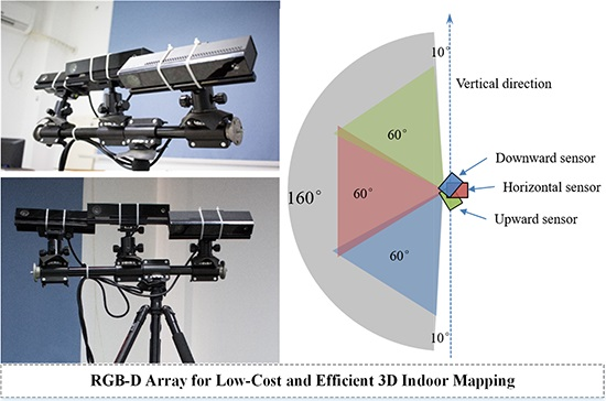
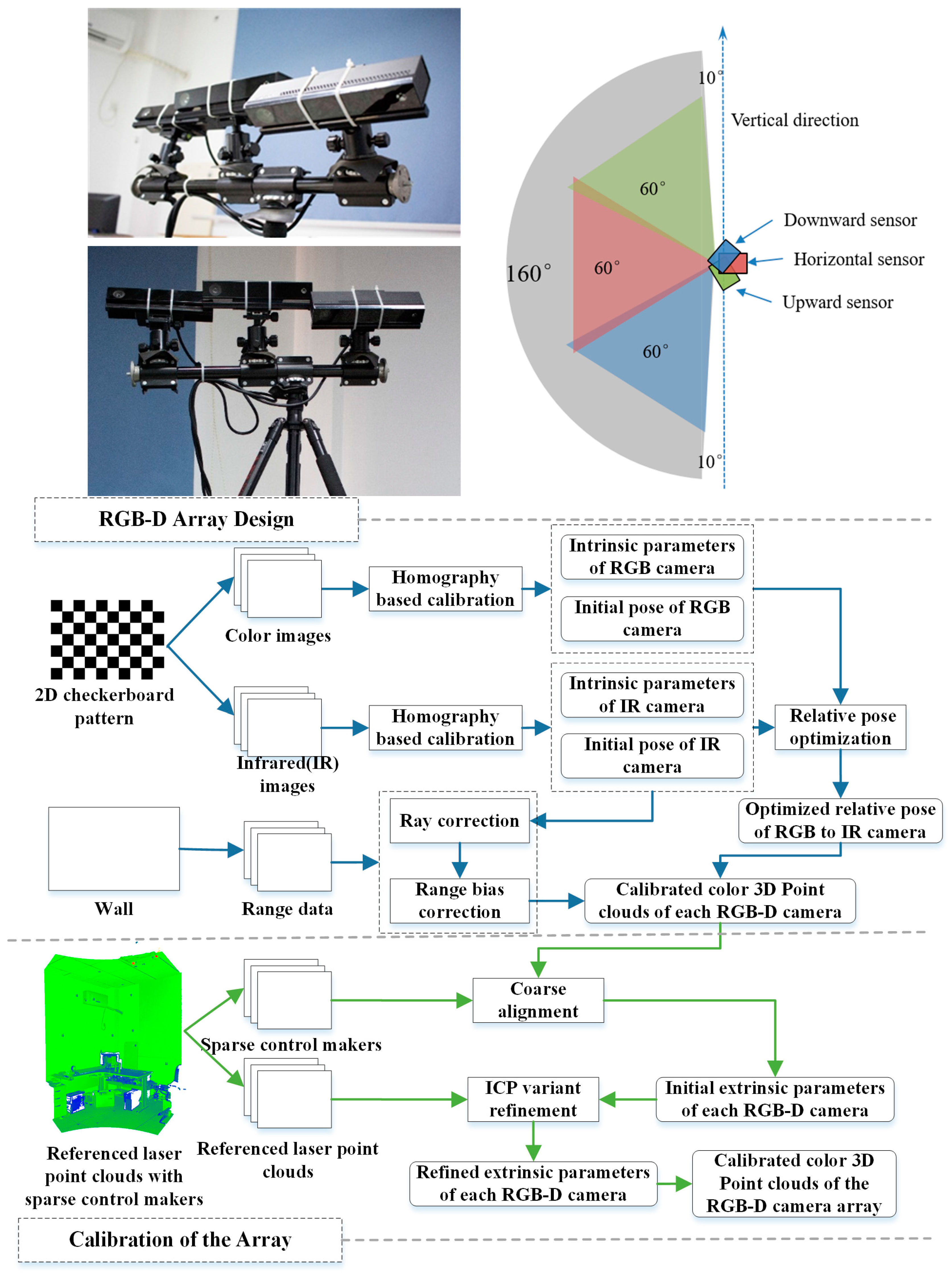
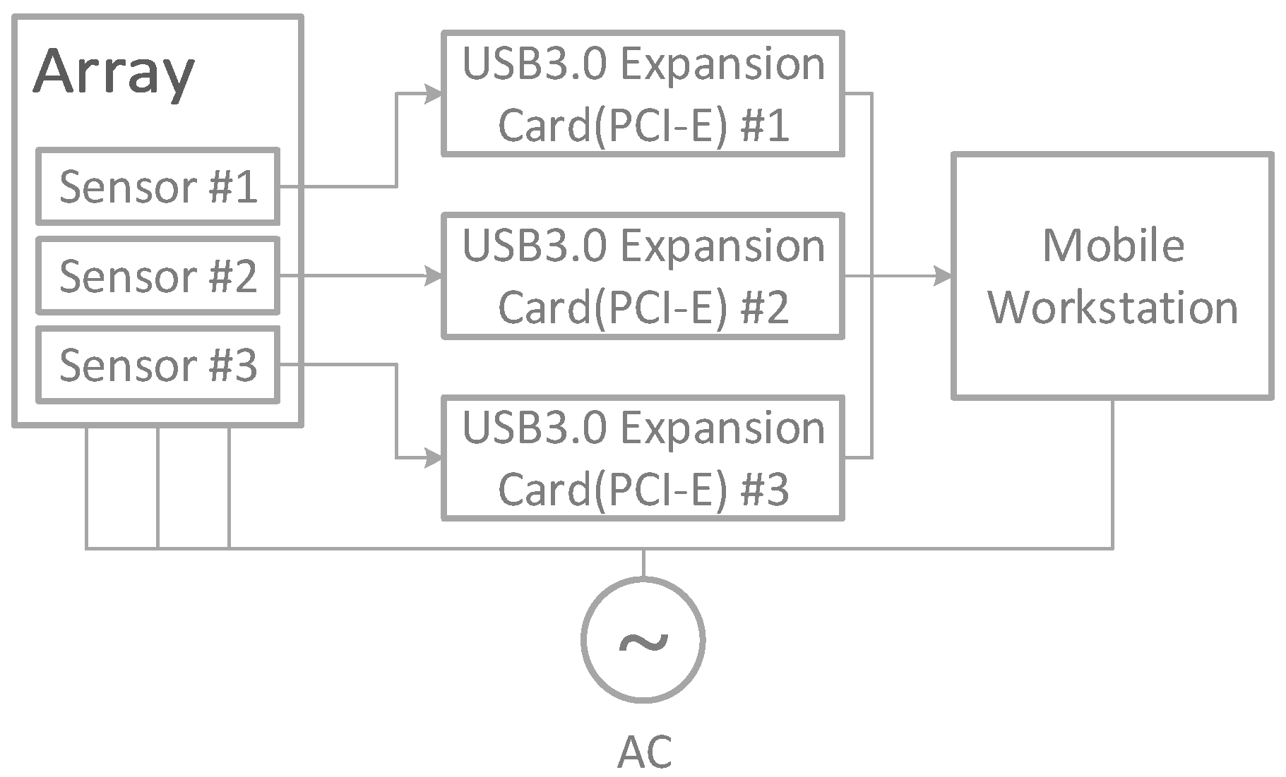
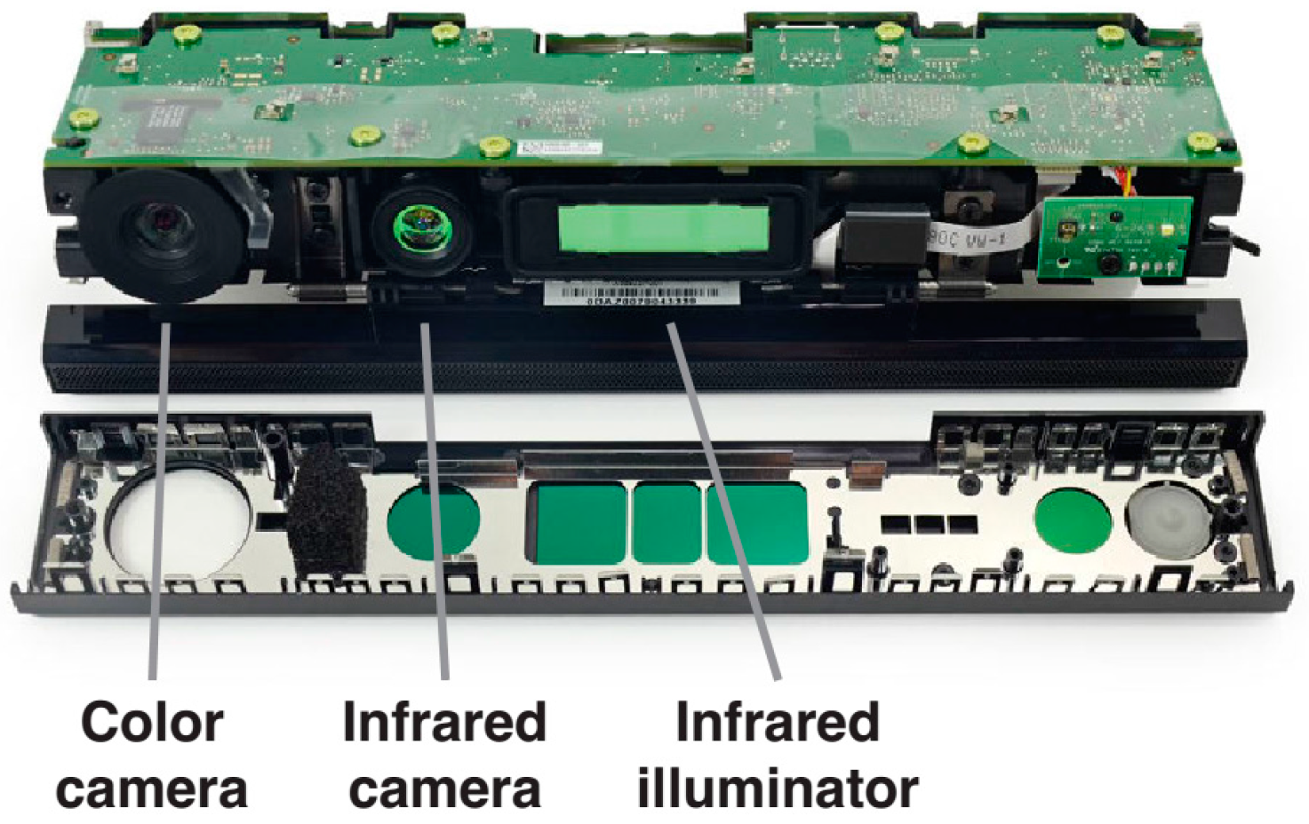
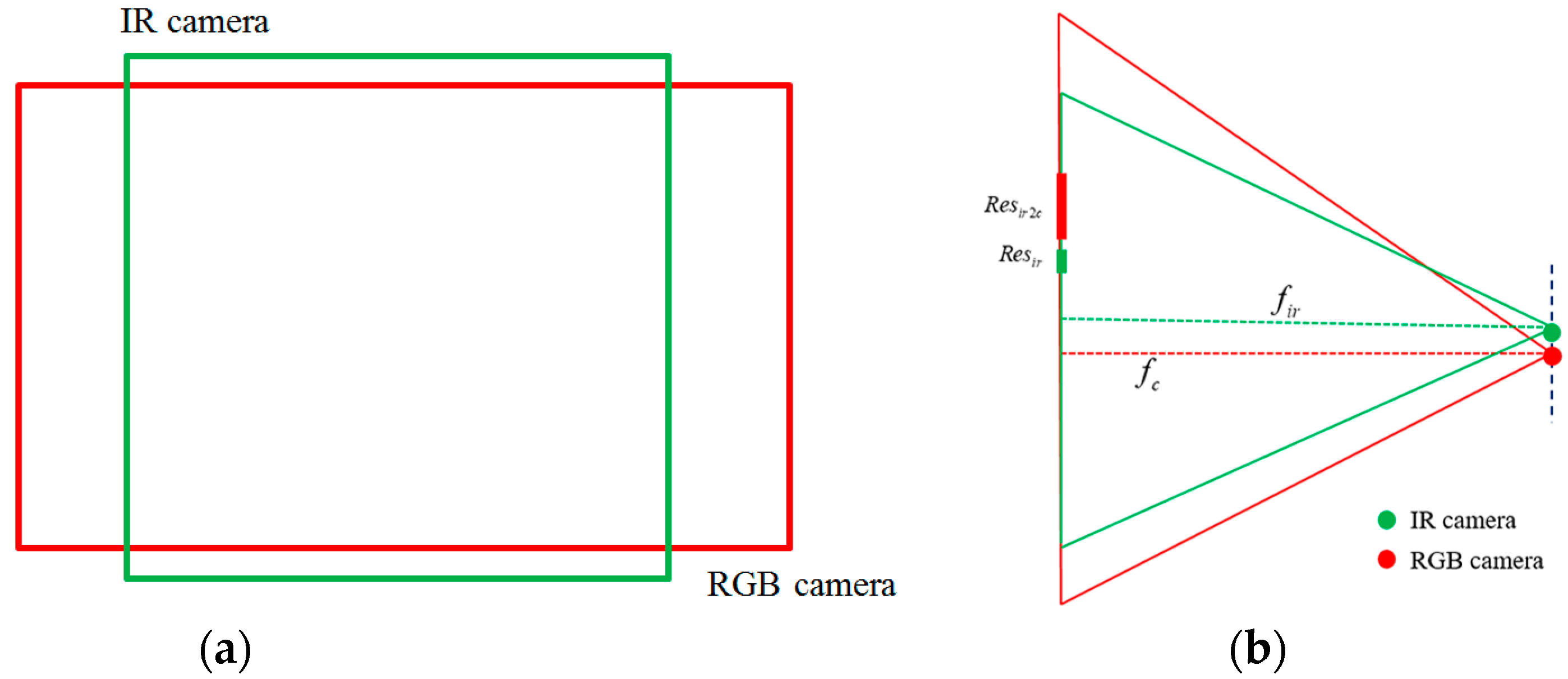
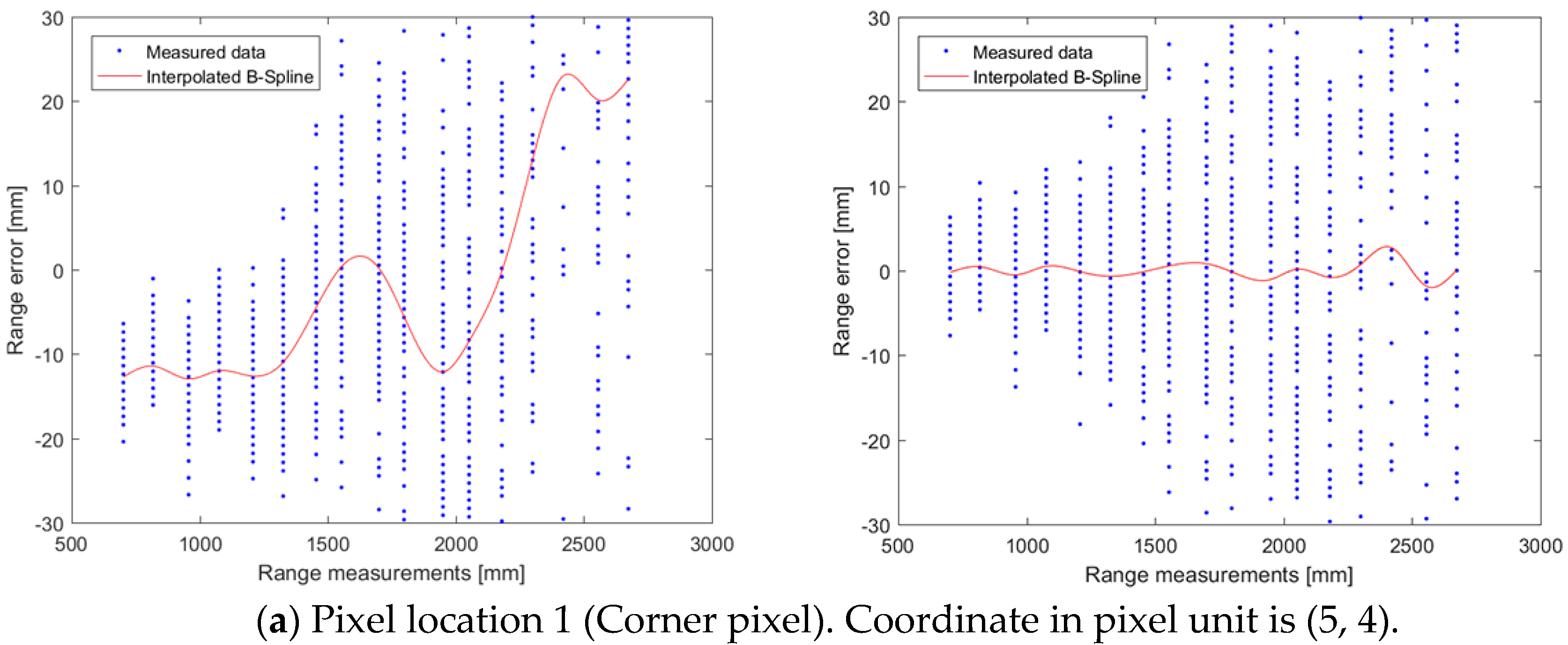
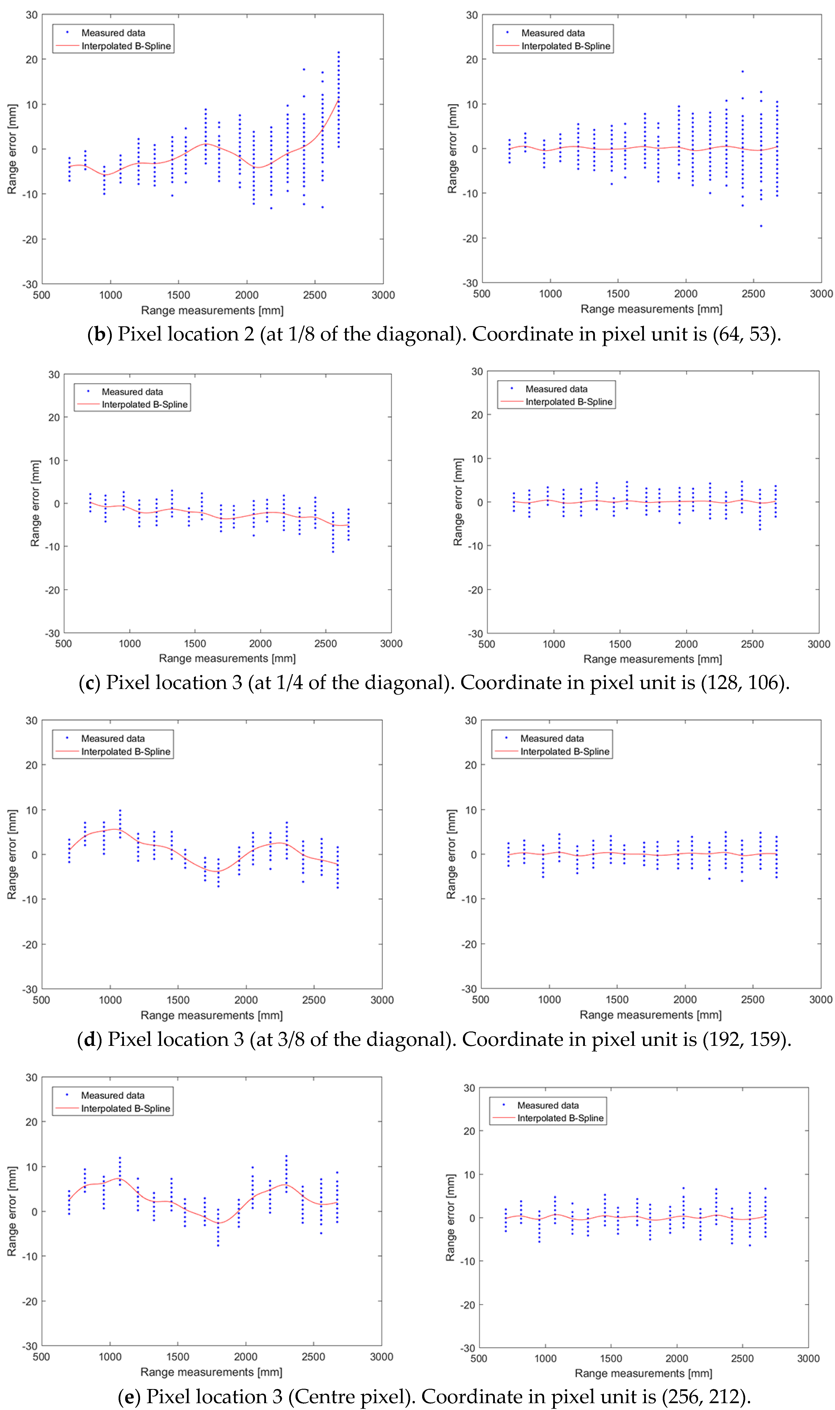
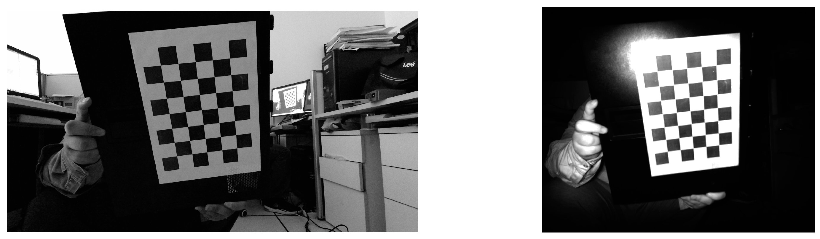
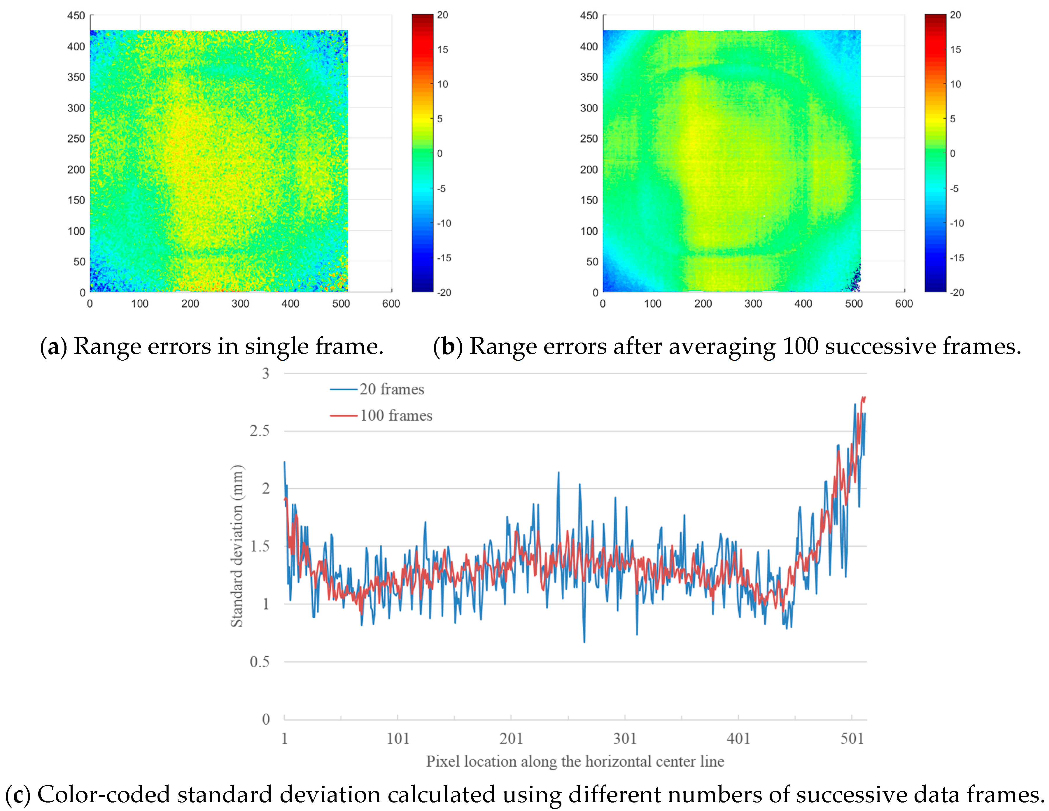
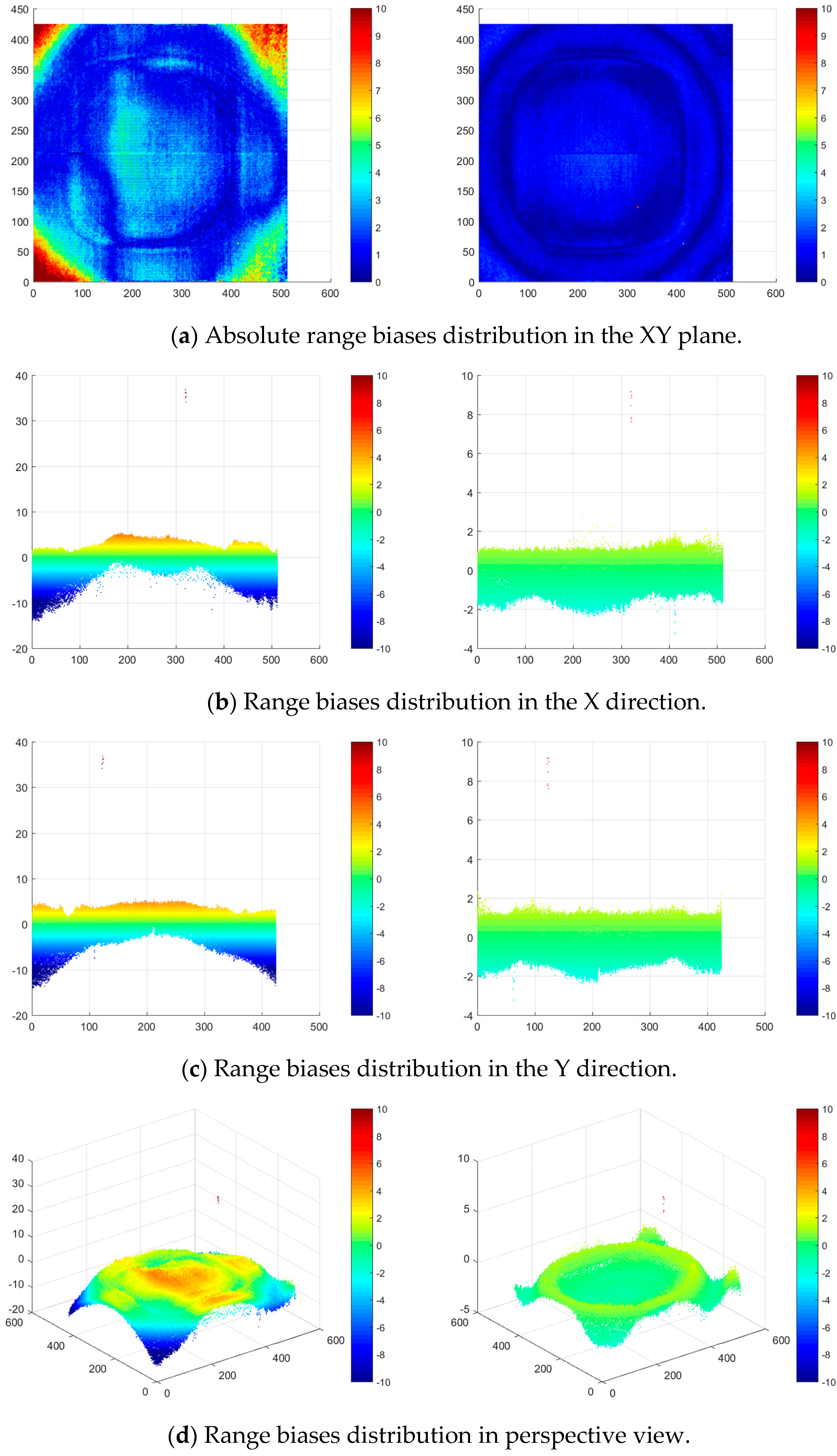
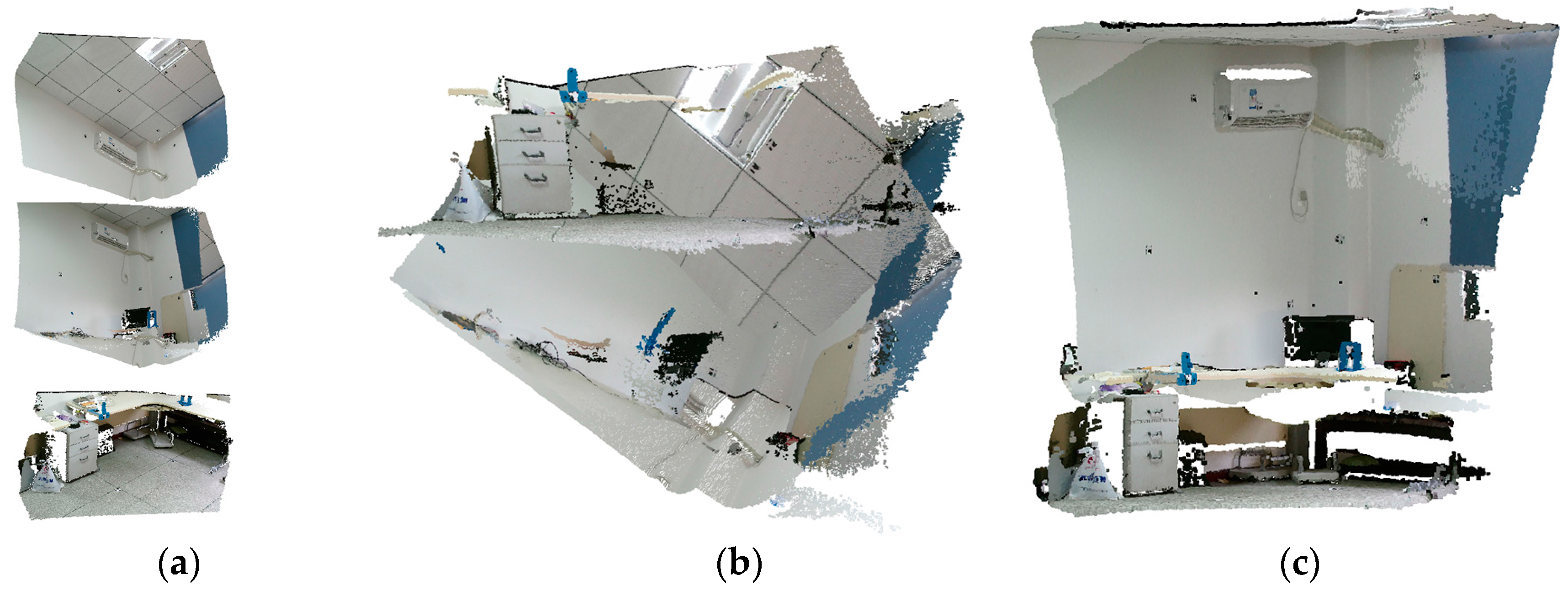
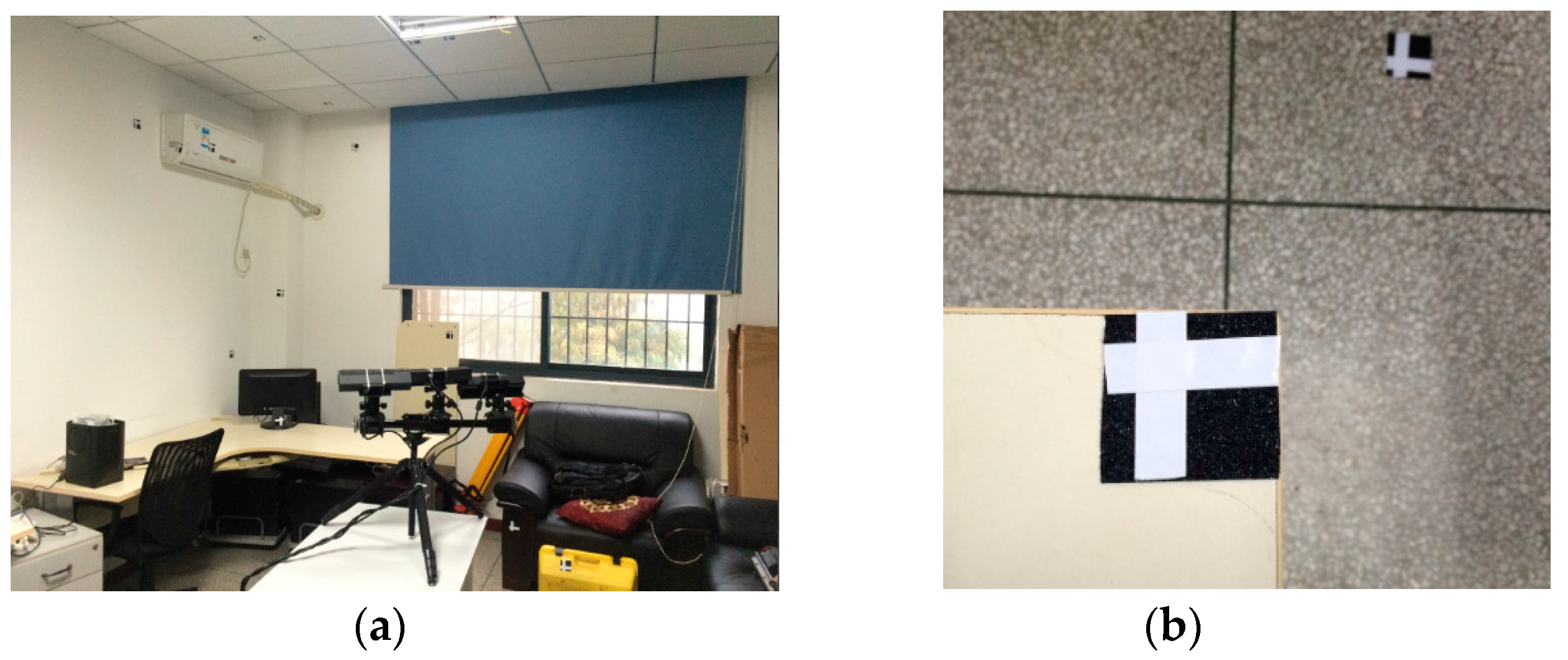
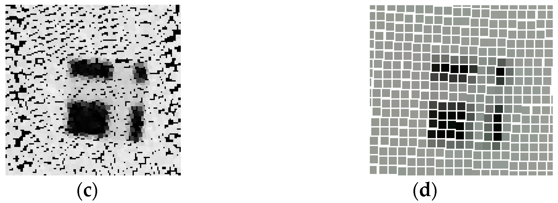
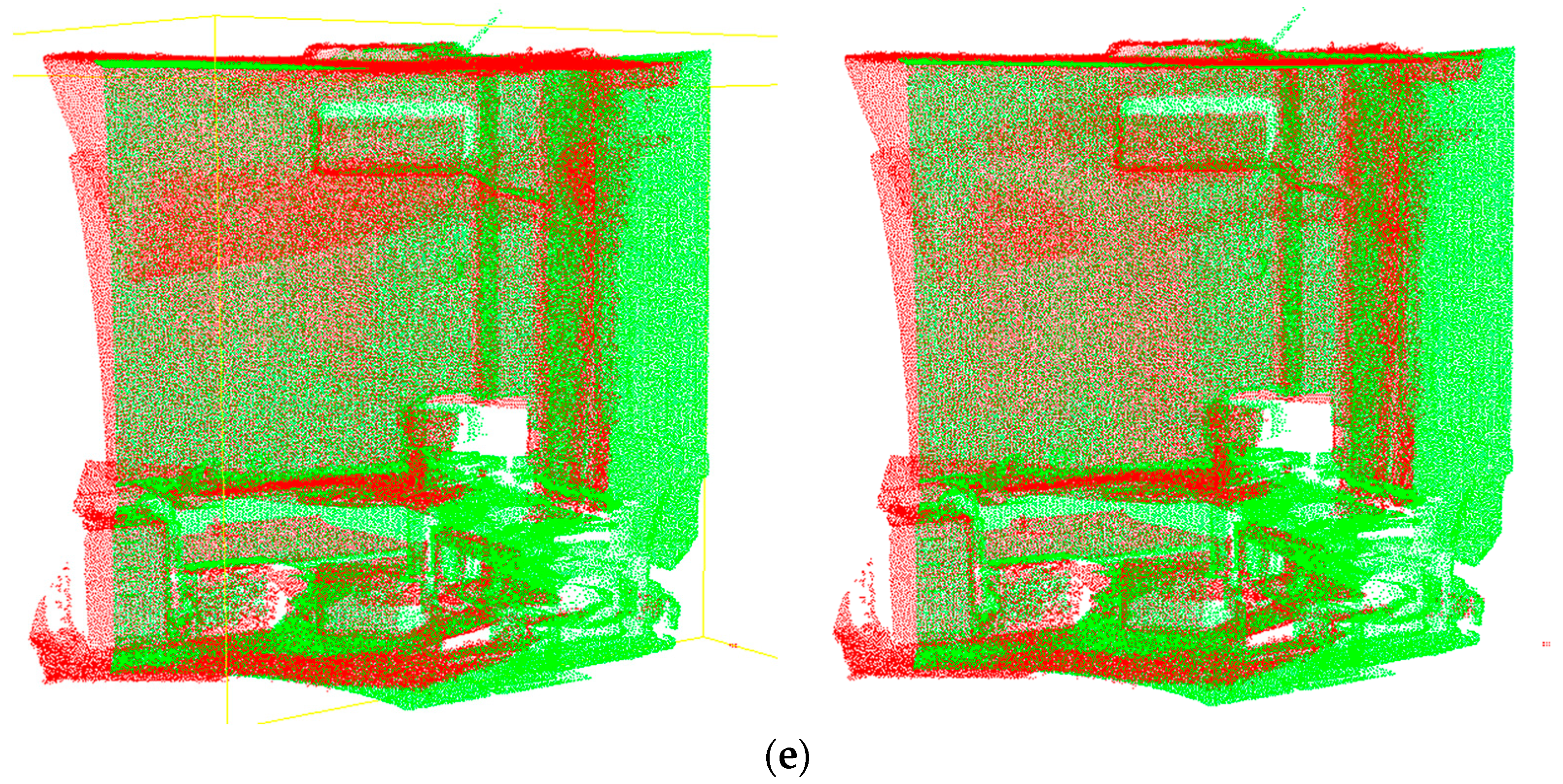
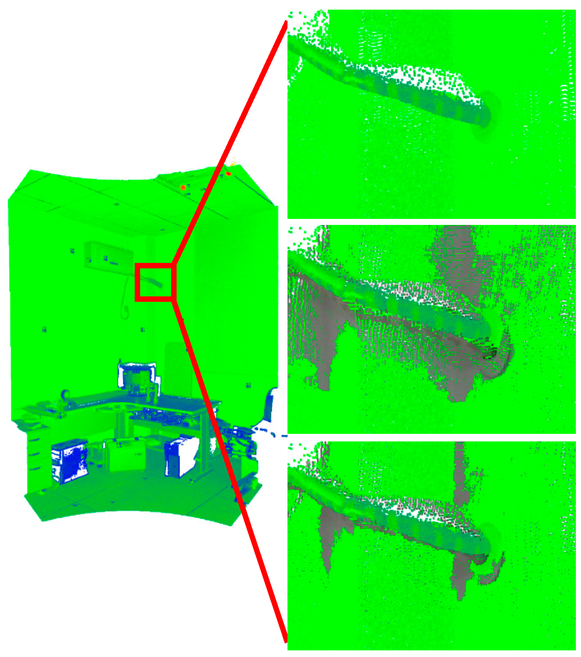
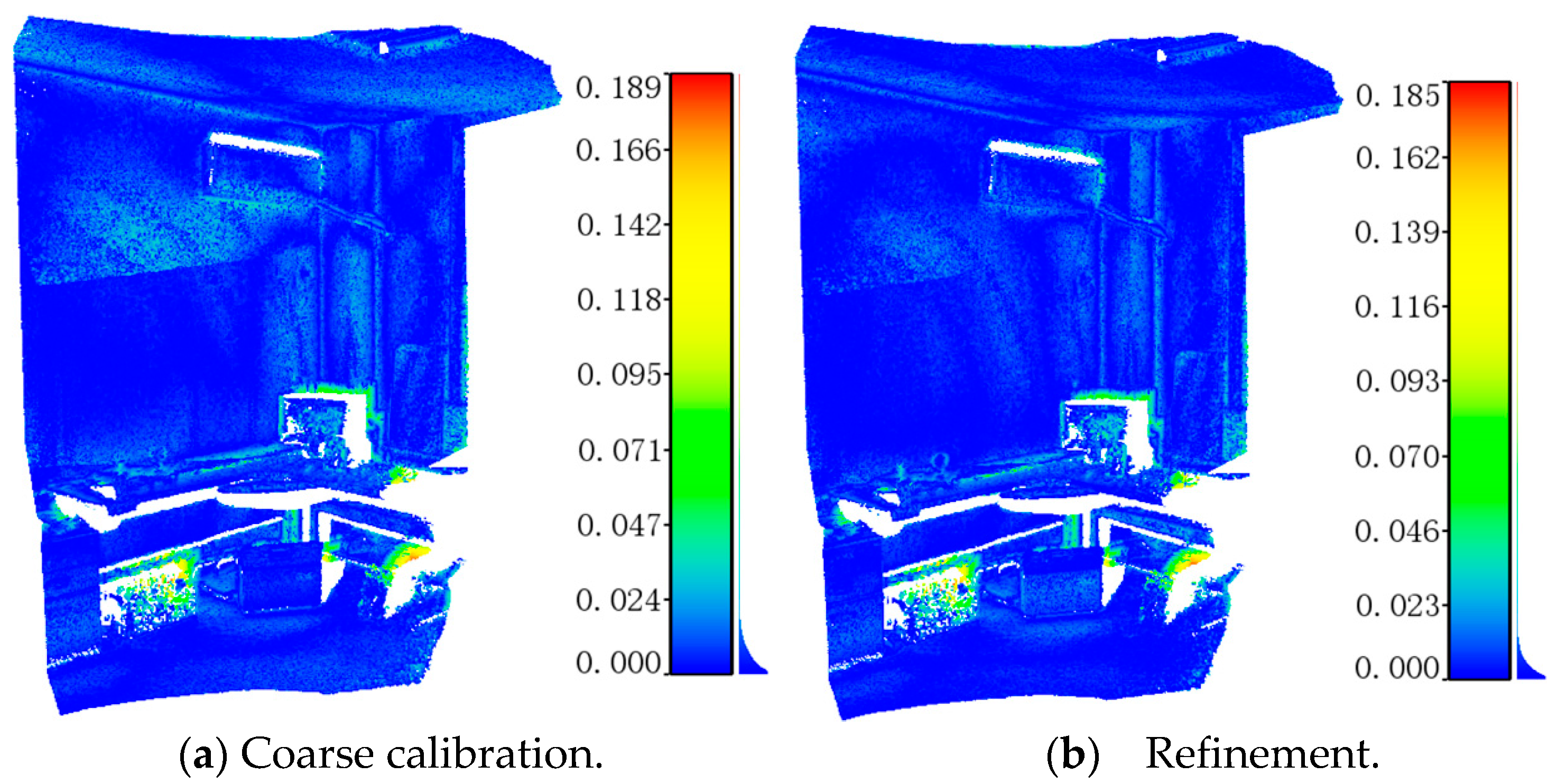
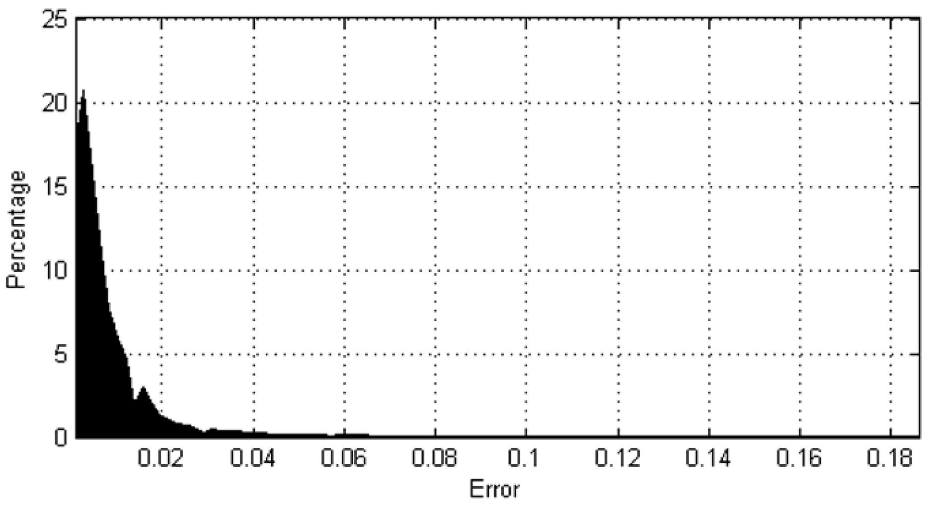
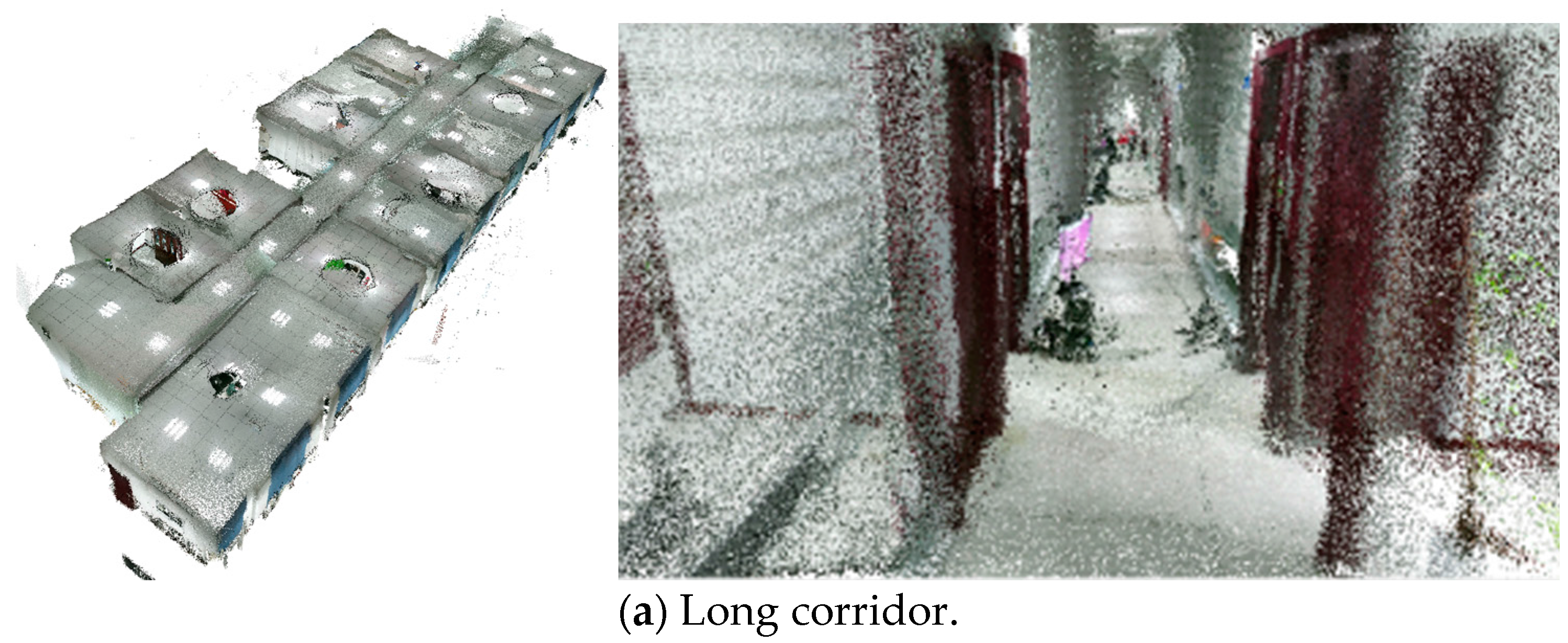
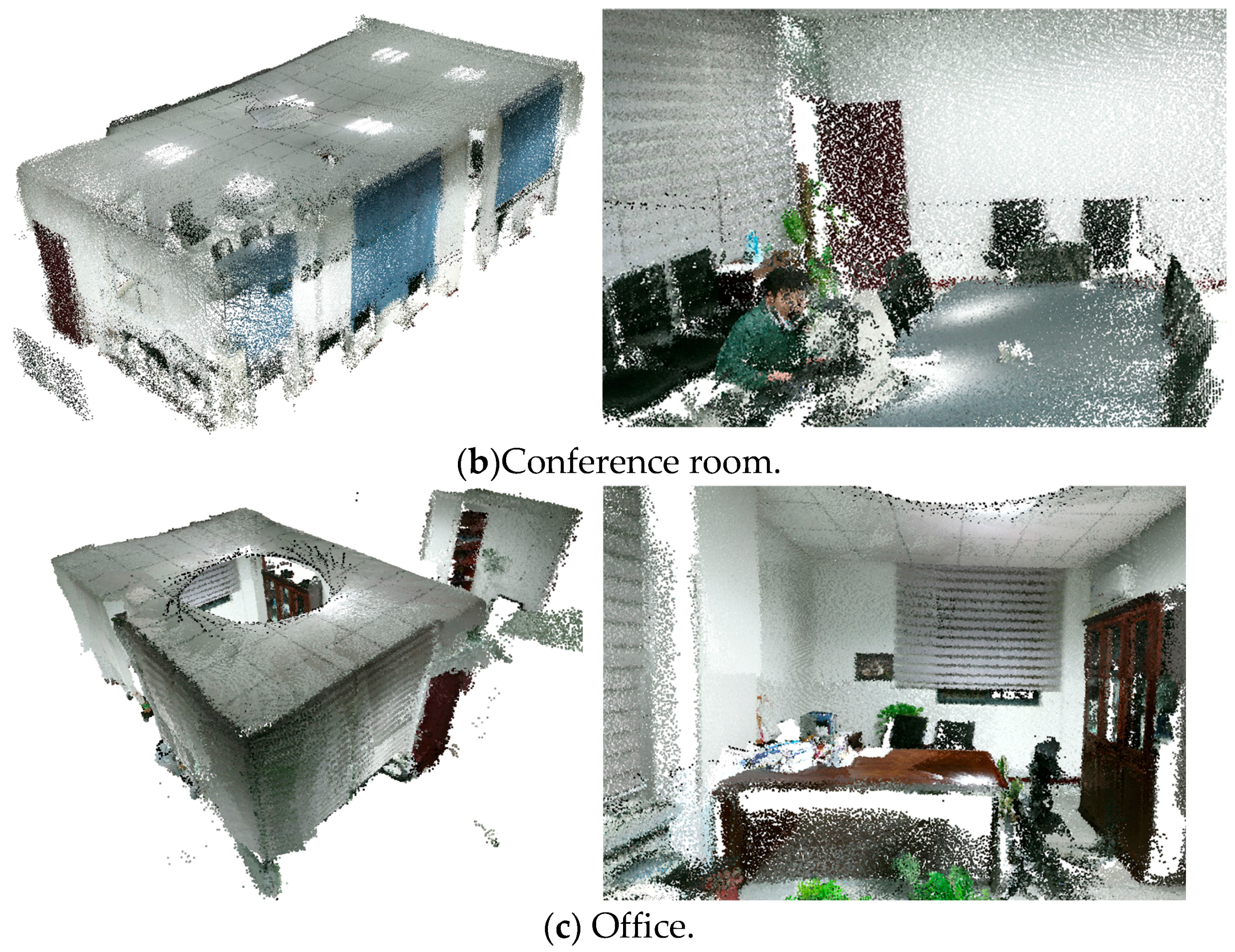
Table 1.
Specifications of the Kinect v2.
| Depth Image Resolution | 512 × 424 pixels |
|---|---|
| Image Resolution | 1920 × 1080 pixels |
| Depth Range | 0.5–4.5 m (Official driver) 0.5–9 m (Open Kinect driver) |
| Validated FOV (H × V) | 70° × 60° |
| Frame Rate | 30 Hz |
Table 2.
Image number for optical-related geometry calibration.
| Sensors | IR Image | Color Image | Sync Image |
|---|---|---|---|
| Sensor #1 | 105 | 112 | 112 |
| Sensor #2 | 125 | 131 | 133 |
| Sensor #3 | 109 | 106 | 108 |
Table 3.
Calibrated intrinsic parameters of the IR/RGB cameras.
| RGB Camera | IR Camera | |||||
|---|---|---|---|---|---|---|
| Upward | Horizontal | Downward | Upward | Horizontal | Downward | |
| (Pixel) | 1.0476 × 10³ | 1.0441 × 10³ | 1.0496 × 10³ | 3.5898 × 10² | 3.6303 × 10² | 3.6079 × 10² |
| (Pixel) | 1.0464 × 10³ | 1.0461 × 10³ | 1.0493 × 10³ | 3.5925 × 10² | 3.6396 × 10² | 3.6104 × 10² |
| u0 | 9.3196 × 10² | 9.4695 × 10² | 9.4030 × 10² | 2.5353 × 10² | 2.4947 × 10² | 2.5407 × 10² |
| v0 | 5.3339 × 10² | 5.3738 × 10² | 5.4417 × 10² | 1.9781 × 10² | 2.1056 × 10² | 2.0385 × 10² |
| k1 | 3.8126 × 10⁻² | 4.4726 × 10⁻² | 3.9747 × 10⁻² | 8.5110 × 10⁻² | 7.0900 × 10⁻² | 9.6235 × 10⁻² |
| k2 | −4.4836 × 10⁻² | −5.5681 × 10⁻² | −4.5250 × 10⁻² | −2.7264 × 10⁻¹ | −2.3734 × 10⁻¹ | −3.2029 × 10⁻¹ |
| k3 | 1.0454 × 10⁻² | 1.4570 × 10⁻² | 4.5968 × 10⁻³ | 1.2137 × 10⁻¹ | 7.8478 × 10⁻² | 1.7748 × 10⁻¹ |
| p1 | −4.4198 × 10⁻³ | 6.1033 × 10⁻³ | 2.5611 × 10⁻³ | −3.0022 × 10⁻³ | 3.0057 × 10⁻³ | −2.5319 × 10⁻³ |
| p2 | −7.0858 × 10⁻³ | −2.7240 × 10⁻⁴ | −5.6884 × 10⁻³ | −2.2251 × 10⁻³ | −5.8013 × 10⁻⁴ | 1.3550 × 10⁻³ |
Table 4.
Pixel projection errors of the optical-related geometry calibration.
| Max Residual Error | RMSE | |
|---|---|---|
| Color #1 | 0.8563 | 0.1830 |
| IR #1 | 0.3793 | 0.0826 |
| Color #2 | 0.9986 | 0.1644 |
| IR #2 | 0.3114 | 0.0695 |
| Color #3 | 0.8071 | 0.2377 |
| IR #3 | 0.3634 | 0.0909 |
Table 5.
Range biases statistics before and after depth calibration (observation distance 1.208 m).
| Bias Range | <1 mm | 1–3 mm | 3–5 mm | 5–10 mm | 10–15 mm | >15 mm |
|---|---|---|---|---|---|---|
| After depth calibration | 81.020% | 18.899% | 0.000 | 0.081% | 0.000% | 0.000% |
| Before depth calibration | 36.374% | 43.063% | 13.441% | 6.470% | 0.573% | 0.081% |
Table 6.
RGB-D array and TLS point clouds registration errors (m).
| Max Residual Error | Mean Residual Error | RMSE | |
|---|---|---|---|
| Coarse calibration | 0.189 | 0.008 | 0.04 |
| Fine calibration | 0.185 | 0.005 | 0.01 |
© 2018 by the authors. Licensee MDPI, Basel, Switzerland. This article is an open access article distributed under the terms and conditions of the Creative Commons Attribution (CC BY) license (http://creativecommons.org/licenses/by/4.0/).
Share and Cite
MDPI and ACS Style
Chen, C.; Yang, B.; Song, S.; Tian, M.; Li, J.; Dai, W.; Fang, L. Calibrate Multiple Consumer RGB-D Cameras for Low-Cost and Efficient 3D Indoor Mapping. Remote Sens. 2018, 10, 328. https://doi.org/10.3390/rs10020328
AMA Style
Chen C, Yang B, Song S, Tian M, Li J, Dai W, Fang L. Calibrate Multiple Consumer RGB-D Cameras for Low-Cost and Efficient 3D Indoor Mapping. Remote Sensing. 2018; 10(2):328. https://doi.org/10.3390/rs10020328
Chicago/Turabian StyleChen, Chi, Bisheng Yang, Shuang Song, Mao Tian, Jianping Li, Wenxia Dai, and Lina Fang. 2018. "Calibrate Multiple Consumer RGB-D Cameras for Low-Cost and Efficient 3D Indoor Mapping" Remote Sensing 10, no. 2: 328. https://doi.org/10.3390/rs10020328
Note that from the first issue of 2016, this journal uses article numbers instead of page numbers. See further details here.