Digital Airborne Photogrammetry—A New Tool for Quantitative Remote Sensing?—A State-of-the-Art Review On Radiometric Aspects of Digital Photogrammetric Images

Abstract
:1. Introduction

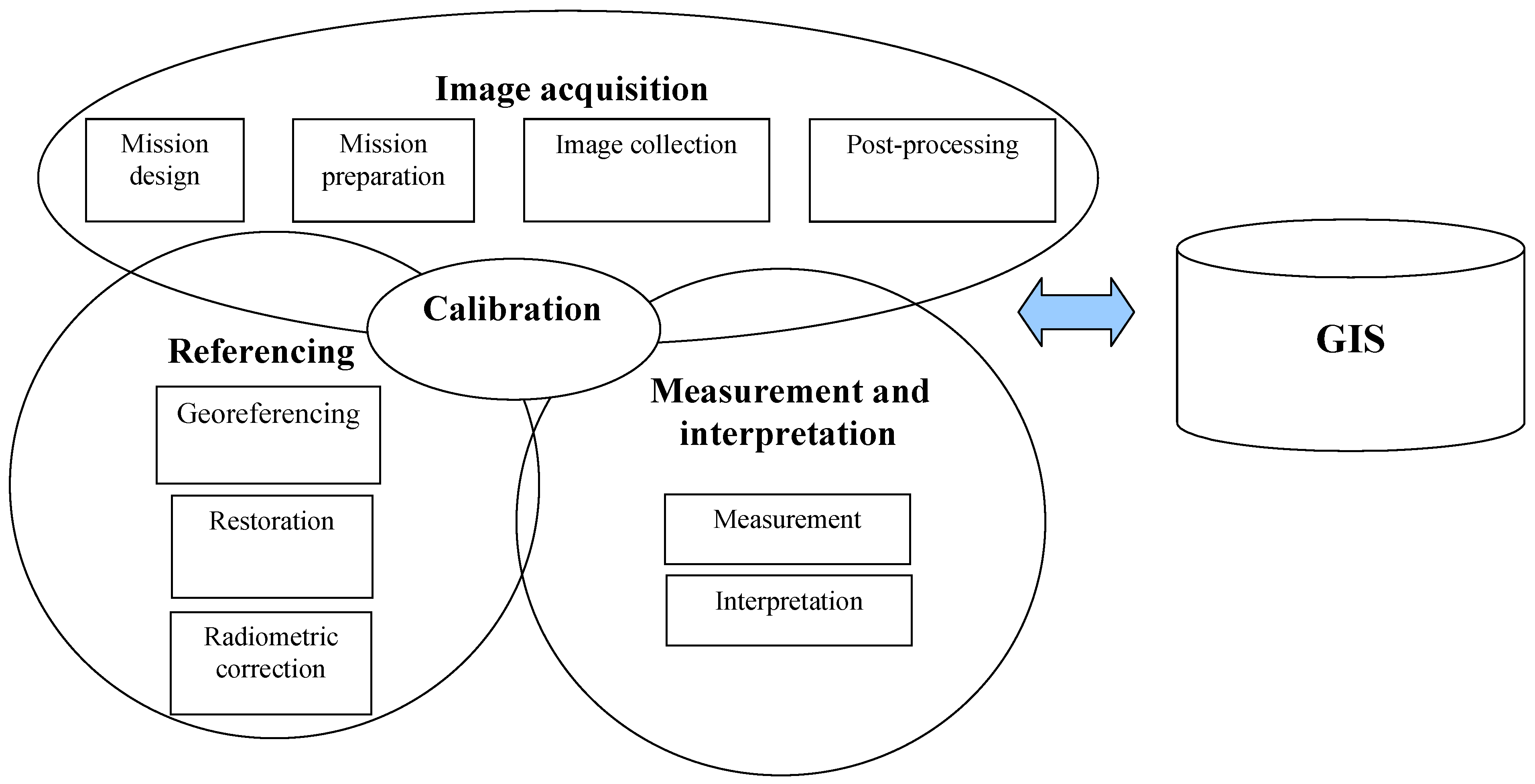
2. Imaging Process
2.1. A digital Photogrammetric Airborne Imaging System

| System | Sensor | Lens, detector, filter, beam splitter, shutter, temeperature/pressure stabilization |
| Other system components | Sensor mount, camera port window, direct orientation system (GNSS, IMU), vehicle | |
| Calibration | Models, parameters, and methods for geometry, spatial resolution and radiometry | |
| Data post-processing | Image post-processing, direct orientation post-processing, georeferencing*, restoration*, radiometric correction* | |
| Photogrammetric network | Block structure | Number of flight lines, number of images, side and forward overlaps, relative orientations |
| Control | GCPs*, direct orientation observations, GNSS base stations, atmospheric observations*, in situ reflectance and illumination measurements, reflectance reference targets*, spatial resolution reference targets* | |
| Conditions | System settings | Aperture, exposure time, FMC, in-flight data processing (e.g. compression) |
| System environment | Altitude, vibrations and swing, velocity, temperature, pressure, humidity | |
| Atmosphere | Refraction, Mie and Rayleigh scattering (visibility), absorption, turbulence, clouds, temperature, pressure, humidity | |
| Illumination | Direct sunlight, diffuse light, solar elevation angle, spectral distribution of light | |
| Object | Structure, contrast, anisotropy, topography, adjacent objects |
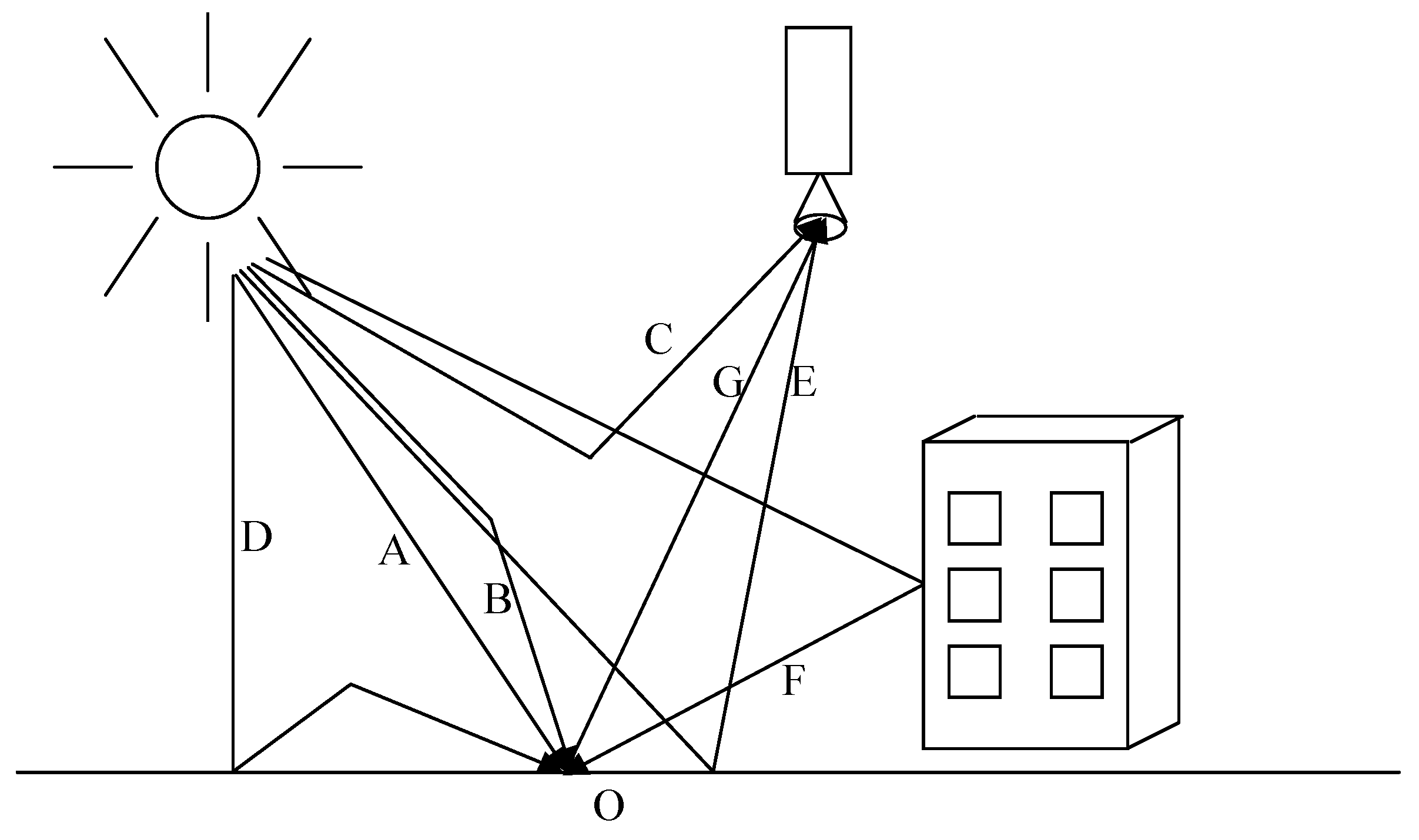
2.2. Image Radiometry in Image Collection Process
2.3. Airborne Imaging Sensors
2.3.1. Digital large-format photogrammetric sensors
2.4. Radiometric Calibration

2.4.1. Radiometric calibration approaches of photogrammetric sensors
2.5. Radiometric Correction
2.5.1. Radiometric correction in photogrammetric systems
3. Questionnaire on Radiometric Processing in Photogrammetric Production Lines
| Participant | Organization | Role |
|---|---|---|
| Institut Cartogràphic Catalonia (ICC) | NMA | Software developer, Data provider, Data user, Research |
| Institut Géographique National, France (IGN) | NMA | Sensor manufacturer, Software developer, Data provider, Data user, Research |
| National Survey and Cadastre, Denmark (KMS) | NMA | Data user |
| National Land Survey, Finland (NLS) | NMA | Data provider, Data user |
| Ordnance Survey, Great Britain (OS) | NMA | Data provider, Data user |
| Land Survey of Switzerland (Swisstopo) | NMA | Data provider, Data user |
| ReSe Applications Scläpfer, Switzerland (ReSe) | Company | Software, consultant |
| Finnish Geodetic Institute, Finland (FGI) | Research | Research |
| Institut für Geoinformatik und Fernerkundung, Universität Osnabrück (IGF) | University | Research |
3.1. Sensor
3.1.1. Current situation
3.1.2. Limitations and desired sensor properties
3.2. Calibration
3.2.1. Current situation in calibration
3.2.2. Limitations and desired calibration process
3.3. Image Collection
3.3.1. Current situation in image collection
| Organization | Sensor | Vehicle | GNSS/IMU | Gyro stab. mount | FMS | Pressurized cabin | Camera port glass |
|---|---|---|---|---|---|---|---|
| ICC | DMC | Partenavia P-68 | Yes | Yes | CCNS | No | No |
| Cessna Citation I | Yes | Yes | CCNS | Yes | Yes | ||
| Cessna Caravan 208N23 | Yes | Yes | CCNS | No | No | ||
| IGN | IGN | Beechcraft Super King Air 200T | GNSS | Yes | Own | Yes | Yes |
| Beechcraft Super King Air B200T | GNSS | Yes | Own | Yes | Yes | ||
| Beechcraft Super King Air B200 | GNSS | Yes | Own | Yes | Yes | ||
| NLS | DMC | Turbo Commander | Yes | Yes | Intergraph | Yes | Yes |
| OS | DMC | Cessna 404 | Yes | Yes | Intergraph | No | No |
| Swisstopo | ADS40 | Beechcraft Super King Air 350C | Yes | Yes | FCMS | Yes | Yes |
| Twin Otter DHC 6-300D | Yes | Yes | FCMS | No | No |
| Organization | Aperture | Exposure time | Flight Speed [knt] | Maximum flight altitude [m] | GSD range [cm] | Refl. ref. targets/Atm. obs |
|---|---|---|---|---|---|---|
| ICC* | A | A | 110-150 | 4300 | 5-43 | No |
| A | A | 145-240 | 8800 | 5-70 | ||
| A | A | 110-160 | 7200 | 5-88 | ||
| IGN* | Fixed | M | 140-180 | 9000 | 20-100** | No |
| Fixed | M | 140-180 | 10650 | 20-100** | ||
| Fixed | M | 140-180 | 10650 | 20-100** | ||
| NLS | A/M | A/M | 120-200 | 10000 | 5-100 | No |
| OS | A/M | A/M | 110-140 | 3000 | 5-25 | No |
| Swisstopo* | Fixed | A/M | 140-180 | 10700 | 5-100 | No |
| Fixed | A/M | 110-140 | 8100 | 5-81 |
- * Different specifications are related to aircrafts in Table 3.
- ** GSD range for the IGN’s version 1 camera, values will be different for the version 2.
| Organization | Visibility/Clouds | Solar elevation [º] | Season [month] | GSD [cm] | Temporal resolution [years] | Application |
|---|---|---|---|---|---|---|
| ICC | No cloud | 30 | mid 3- | 25 | 1 | Orthophotos |
| mid 10 | Stereomapping | |||||
| Classification | ||||||
| IGN | Visibility > 15 km Clouds: <5%/image, <1%/mission | 30 | mid 4- | 20-50 | 5 | Orthophotos |
| mid 10 | Stereomapping | |||||
| Classification | ||||||
| KMS | Good visibility No cloud | 25 | 3-4 | 10, 20 | 1, 3 | Orthophotos |
| no leaf | Stereomapping | |||||
| NLS | No cloud | 30 (25) | mid 4-8 | 30, 50 | 5-10 | Orthophotos |
| Stereomapping | ||||||
| OS | No cloud | 25 | 3-11 | 15, 20, 25 | 2-8 | Orthophotos |
| Stereomapping | ||||||
| Swisstopo | No cloud | 40 | 4-9 | 25, 50 | 3 | Orthophotos |
| Stereomapping |
3.3.2. Limitations and desired image collection process
3.4. Post-processing
3.4.1. Current approaches for post-processing
3.4.2. Limitations and desired post-processing approach
| ICC | Post-processing after image collection by Intergraph PPS |
| |
| Orthophotos by own software (pansharpened, 4-band images) | |
| |
| |
| Remote sensing images by own software (non-pansharpened, 4 band images) | |
| |
| |
| IGN | Post-processing after image collection by own software |
| |
| Orthophotos, stereo models and classification images by own software (8 bit, 4-band images) | |
| |
| |
| |
| NLS | Post-processing after image collection by Intergraph PPS |
| |
| Stereomodels and orthophotos by BAE Systems Socet Set/ORIMA (pansharpened, 8-bit, 4-band images) | |
| OS | Post-processing after image collection by Intergraph PPS |
| |
| Orthophotos by BAE Systems Socet Set and Intergraph ISAT (8 bit images) | |
| |
| |
| Swisstopo | Post-processing after image collection by Leica Geosystems GPRO |
| |
| Orthophotos by Leica Geosystems GPRO (8 bit RGB images with all corrections, NIR channel with less processing) | |
| |
| |
| |
| |
| Stereomodels by Leica Geosystems GPRO | |
|
3.5. Utilization of the Images
3.5.1. Current situation in photogrammetric applications
3.5.2. Limitations and desired applications
4. Discussion and Conclusions
| Type | Sensor manufacturing | Software development | Data collection | Image products | Applications | Research |
|---|---|---|---|---|---|---|
| U1 | x | x | x | x | x | (x) |
| U2 | x | x | x | x | (x) | |
| U3 | x | x | x | (x) | ||
| U4 | x | x | (x) | |||
| U5 | x | (x) | ||||
| P1 | x | x | x | (x) | ||
| P2 | x | x | x | x | (x) | |
| P3 | x | (x) | ||||
| P4 | x | x | (x) | |||
| R1 | x | |||||
| SW1 | x | (x) | ||||
| M1 | x | x | (x) |
Acknowledgements
References and Notes
- Honkavaara, E. Calibrating Digital Photogrammetric Airborne Imaging Systems Using a Test Field. Ph.D. Dissertation, Helsinki University of Technology, Espoo, Finland, 2008. [Google Scholar]
- Markelin, L.; Honkavaara, E.; Peltoniemi, J.; Ahokas, E.; Kuittinen, R.; Hyyppä, J.; Suomalainen, J.; Kukko, A. Radiometric calibration and characterization of large-format digital photogrammetric sensors in a test field. Photogramm. Eng. Remote Sens. 2008, 74, 1487–1500. [Google Scholar] [CrossRef]
- Johnson, B.C.; Brown, S.W.; Rice, J.P. Metrology for remote sensing radiometry. In Post-Launch Calibration of Satellite Sensors, Proceedings of the International Workshop on Radiometric and Geometric Calibration, Gulfport, MS, USA, December 2-5, 2003; Morain, S.A., Budge, A.M., Eds.; Taylor & Francis: London, UK, 2004; pp. 7–16. [Google Scholar]
- Schowengerdt, R.A. Remote Sensing, Models and Methods for Image Processing, 2nd Edition ed; Academic Press Inc: San Diego, CA, USA, 1997. [Google Scholar]
- Lillesand, T.; Kiefer, R. Remote Sensing and Image Interpretation—4th Edition; John Wiley & Sons: Hoboken, NJ, USA, 2000. [Google Scholar]
- Liang, S. Quantitative Remote Sensing of Land Surfaces; John Wiley & Sons: Hoboken, NJ, USA, 2004. [Google Scholar]
- Read, R.E.; Graham, R.W. Manual of Air Survey: Primary Data Acquisition; Whittles Publishing: Caithness, Scotland, UK, 2002. [Google Scholar]
- Fricker, P.; Sandau, R.; Walker, A.S. Digital photogrammetric cameras: possibilities and problems. In Photogrammetric Week ´99; Fritsch, D., Spiller, R., Eds.; Wichmann Verlag: Heidelberg, Germany, 1999; pp. 71–82. [Google Scholar]
- Spiller, R.H. Z/I Imaging: A new system provider for photogrammetry and GIS. In Photogrammetric Week ´99; Fritsch, D., Spiller, R., Eds.; Wichmann Verlag: Heidelberg, Germany, 1999; pp. 35–42. [Google Scholar]
- Schiewe, J. Status and future perspectives of the application potential of digital airborne sensor systems. Int. J. Appl. Earth Obs. 2005, 6, 215–228. [Google Scholar] [CrossRef]
- Haest, B.; Biesemans, J.; Horsten, W.; Everaerts, J.; Van Camp, N.; Van Valckenborgh, J. Radiometric calibration of digital photogrammetric camera image data. In Proceedings of the ASPRS 2009 Annual Conference, Baltimore, MA, USA, March 9-13, 2009.
- Internet pages of the EuroSDR Radiometry project. http://www.fgi.fi/EuroSDR (accessed August 11, 2009).
- Honkavaara, E.; Arbiol, R.; Markelin, L.; Martinez, L.; Cramer, M.; Korpela, I.; Bovet, S.; Thom, C.; Chandelier, L.; Ilves, R.; Klonus, S.; Reulke, R.; Marshall, P.; Tabor, M.; Schläpfer, D.; Veje, N. Status report of the EuroSDR project “Radiometric aspects of digital photogrammetric airborne images”. In Proceedings of the ISPRS Hannover Workshop 2009, Hannover, Germany, June 2-5, 2009.
- Reulke, R.; Franke, K.H.; Fricker, P.; Pomierski, T.; Sandau, R.; Schoenermark, M.; Tornow, C.; Wiest, L. Target Related Multispectral and True Color Optimization of the Color Channels of the LH Systems ADS40. In International Archives of Photogrammetry and Remote Sensing, Proceedings of the XIX ISPRS Congress, Commission I, Amsterdam, The Netherlands, July 16-22, 2000; 33(1). pp. 244–250.
- Börner, A.; Wiest, L.; Keller, P.; Reulke, R.; Richter, R.; Schaepman, M.; Schläpfer, D. SENSOR: A tool for the simulation of hyperspectral remote sensing systems. ISPRS J. Photogramm. 2001, 55, 299–312. [Google Scholar] [CrossRef]
- Schaepman, M.; Schläpfer, D.; Itten, K.; Strobl, P.; Mooshuber, W.; Müller, A.; Debruyn, W.; Reusen, I.; Ransaer, R. Performance and Calibration Requirements for APEX—Summary Final Report; Remote Sensing Laboratories, Department of Geography, University of Zürich; Doc. Ref.: APEX-SFR, Issue: 1.1, Date: 20.2; 2006. [Google Scholar]
- Chandrasekhar, S. Radiative Transfer; Dover Publications: New York, NY, USA, 1960. [Google Scholar]
- Iqbal, M. An Introduction to Solar Radiation; Academic Press: New York, NY, USA, 1983. [Google Scholar]
- Beisl, U. Correction of Bidirectional Effects in Imaging Spectrometer Data.Remote Sensing Series, 37; Remote Sensing Laboratories, Department of Geography, University of Zürich: Zürich, Switzerland, 2001; p. 188. [Google Scholar]
- Nicodemus, F.E.; Richmond, J.C.; Hsia, J.J.; Ginsberg, I.W.; Limperis, T. Geometrical Considerations and Nomenclature for Reflectance; U.S. National Bureau of Standards: Washington, DC, USA, 1977; p. 67. [Google Scholar]
- Schaepman-Strub, G.; Schaepman, M.E.; Painter, T.H.; Dangel, S.; Martonchik, J.V. Reflectance quantities in optical remote sensing—definitions and case studies. Remote Sen. Env. 2006, 103, 27–42. [Google Scholar]
- Graham, R.; Koh, A. Digital Aerial Survey: Theory and Practice; Whittles Publishing: Chaitness, Scotland, UK, 2002. [Google Scholar]
- Petrie, G.; Walker, S. Airborne digital imaging technology: a new overview. Photogramm. Record 2007, 22, 203–225. [Google Scholar] [CrossRef]
- Sandau, R.; Braunecker, B.; Driescher, H.; Eckardt, A.; Hilbert, S.; Hutton, J.; Kirchhofer, W.; Lithopoulos, E.; Reulke, R.; Wicki, S. Design principles of the LH Systems ADS40 Airborne Digital Sensor. In International Archives of Photogrammetry and Remote Sensing, Proceedings of the XIX ISPRS Congress, Commission I, Amsterdam, The Netherlands, July 16-22, 2000; 33(1). pp. 258–265.
- Fricker, P. Raising the bar for multi-band, high-resolution airborne imagery. In Photogrammetric Week ´07; Fritsch, D., Ed.; Wichmann Verlag: Heidelberg, Germany, 2007; pp. 71–79. [Google Scholar]
- Hinz, A.; Dörstel, C.; Heier, H. DMC – The digital sensor technology of Z/I-Imaging. In Photogrammetric Week 01’; Fritsch, D., Spiller, R., Eds.; Wichmann Verlag: Heidelberg, Germany, 2001; pp. 93–103. [Google Scholar]
- Rosengarten, H. Intergraph’s PhoWo Message. In Photogrammetric Week ´07; Fritsch, D., Ed.; Wichmann Verlag: Heidelberg, Germany, 2007; pp. 19–25. [Google Scholar]
- Leberl, F.; Gruber, M. Flying the new large format digital aerial camera Ultracam. In Photogrammetric Week ´03; Fritsch, D., Ed.; Wichmann Verlag: Heidelberg, Germany, 2003; pp. 67–76. [Google Scholar]
- Gruber, M. UltraCamX, the new digital aerial camera system by Microsoft Photogrammetry. In Photogrammetric Week ´07; Fritsch, D., Ed.; Wichmann Verlag: Heidelberg, Germany, 2007; pp. 137–145. [Google Scholar]
- Paparoditis, N.; Souchon, J.P.; Martinoty, G.; Pierrot-Deseilligny, M. High-end aerial digital cameras and their impact on the automation and quality of the production environment. ISPRS J. Photogramm. 2006, 60, 400–412. [Google Scholar] [CrossRef]
- Souchon, J.P.; Paparoditis, N.; Martin, O.; Meynard, C.; Thom, C. Is there an ideal digital aerial camera? In International Archives of Photogrammetry, Remote Sensing and Spatial Information Sciences, Proceedings of the ISPRS Commission I Symposium; Marne-la-Vallée, Paris, France: July 4-6, 2006 36(A1)..
- Grenzdörffer, G. Medium format digital cameras—a EuroSDR project. In International Archives of the Photogrammetry, Remote Sensing and Spatial Information Sciences, Proceedings of the XXI ISPRS Congress, Commission I, Beijing, China, July 3-11, 2008. 37(B1).
- Morain, A.S.; Zanoni, M.V. Joint Isprs/Ceos-Wgcv task force on radiometric and geometric calibration. In International Archives of Photogrammetry and Remote Sensing, Proceedings of the XX ISPRS Congress, Commission I, Istanbul, Turkey, July 12-23, 2004; 35(1). pp. 354–360.
- Dianguirard, M.; Slater, P.N. Calibration of space-multispectral imaging sensors: A review. Remote Sens. Environ. 1999, 68, 194–205. [Google Scholar] [CrossRef]
- Gege, P.; Fries, J.; Haschberger, P.; Schötz, P.; Schwarzer, H.; Strobl, P.; Suhr, N.; Ulbrich, G.; Jan Vreeling, W. Calibration facility for airborne imaging spectrometers. ISPRS J. Photogramm. 2009, 64, 387–397. [Google Scholar]
- Beisl, U. 2006. Absolute spectroradiometric calibration of the ADS40 sensor. In International Archives of Photogrammetry, Remote Sensing and Spatial Information Sciences, Proceedings of the ISPRS Commission I Symposium; Marne-la-Vallée, Paris, France: July 4-6, 2006 36(B1).
- Hefele, J. Calibration experience with the DMC. In Proceedings of the International Calibration and Orientation Workshop EuroCOW 2006, Castelldefels, Spain; January 25-27, 2006. [Google Scholar]
- Martínez, L.; Arbiol, R.; Palà, V.; Pérez, F. Digital Metric Camera radiometric and colorimetric calibration with simultaneous CASI imagery to a CIE Standard Observer based colour space. In Proceedings of the IEEE International Geoscience and Remote Sensing Symposium, Barcelona, Spain; July 23-28, 2007. [Google Scholar]
- Schläpfer, D.; Nieke, J.; Itten, K.I. Spatial PSF non-uniformity effects in airborne pushbroom imaging spectrometry data. IEEE Trans. Geosci. Remot. Sen. 2007, 45, 458–468. [Google Scholar] [CrossRef]
- Vane, G.; Green, R.O.; Chrien, T.G.; Enmark, H.T.; Hansen, E.G.; Porter, W.M. The airborne visible/infrared imaging Spectrometer (AVIRIS). Remote Sens. Environ. 1993, 44, 127–143. [Google Scholar] [CrossRef]
- Pagnutti, M.; Holekamp, K.; Ryan, R.; Blonski, S.; Sellers, R.; Davis, B.; Zanoni, V. Measurement sets and sites commonly used for characterizations. In International Archives of Photogrammetry and Remote Sensing, Proceedings of the ISPRS Commission I Symposium, Denver, CO, USA, November 10-15, 2002. 34(1).
- Internet pages of CEOS Reference test sites. http://calval.cr.usgs.gov/sites_catalog_ceos_sites.php (accessed August 11, 2009).
- Brown, D.C. The bundle adjustment—progress and prospects. In International Archives of Photogrammetry, Commission 3, Invited Papers, Proceedings of XIII ISP Congress; Helsinki, Finland, 1976.
- Fraser, C.S. Digital camera self-calibration. ISPRS J. Photogramm. 1997, 52, 149–159. [Google Scholar] [CrossRef]
- Secker, J.; Staenz, K.; Gauthier, R.P.; Budkewitsch, P. Vicarious calibration of airborne hyperspectral sensors in operational environments. Remote Sen. Environ. 2001, 76, 81–92. [Google Scholar] [CrossRef]
- Peleg, K.; Anderson, G.L.; Yang, C. Repeatability of hyperspectral imaging systems—quantification and improvement. Int. J. Remote Sens. 2005, 26, 115–139. [Google Scholar] [CrossRef]
- Gianinetto, M.; Lechi, G. A new methodology for in-flight radiometric calibration of the MIVIS imaging sensor. Ann. Geophys-Italy 2006, 49, 65–70. [Google Scholar]
- Beisl, U.; Telaar, J.; von Schönemark, M. Atmospheric correction, reflectance calibration and BRDF correction for ADS40 image data. In International Archives of the Photogrammetry, Remote Sensing and Spatial Information Sciences, Proceedings of the XXI ISPRS Congress, Commission VII, Beijing, China, July 3-11, 2008. 37(B7).
- Diener, S.; Kiefner, M.; Dörstel, C. Radiometric normalisation and colour composite generation of the DMC. In International Archives of Photogrammetry and Remote Sensing, Proceedings of the XIX ISPRS Congress, Commission I, Amsterdam, The Netherlands, July 16-22, 2000; 33(1). pp. 82–88.
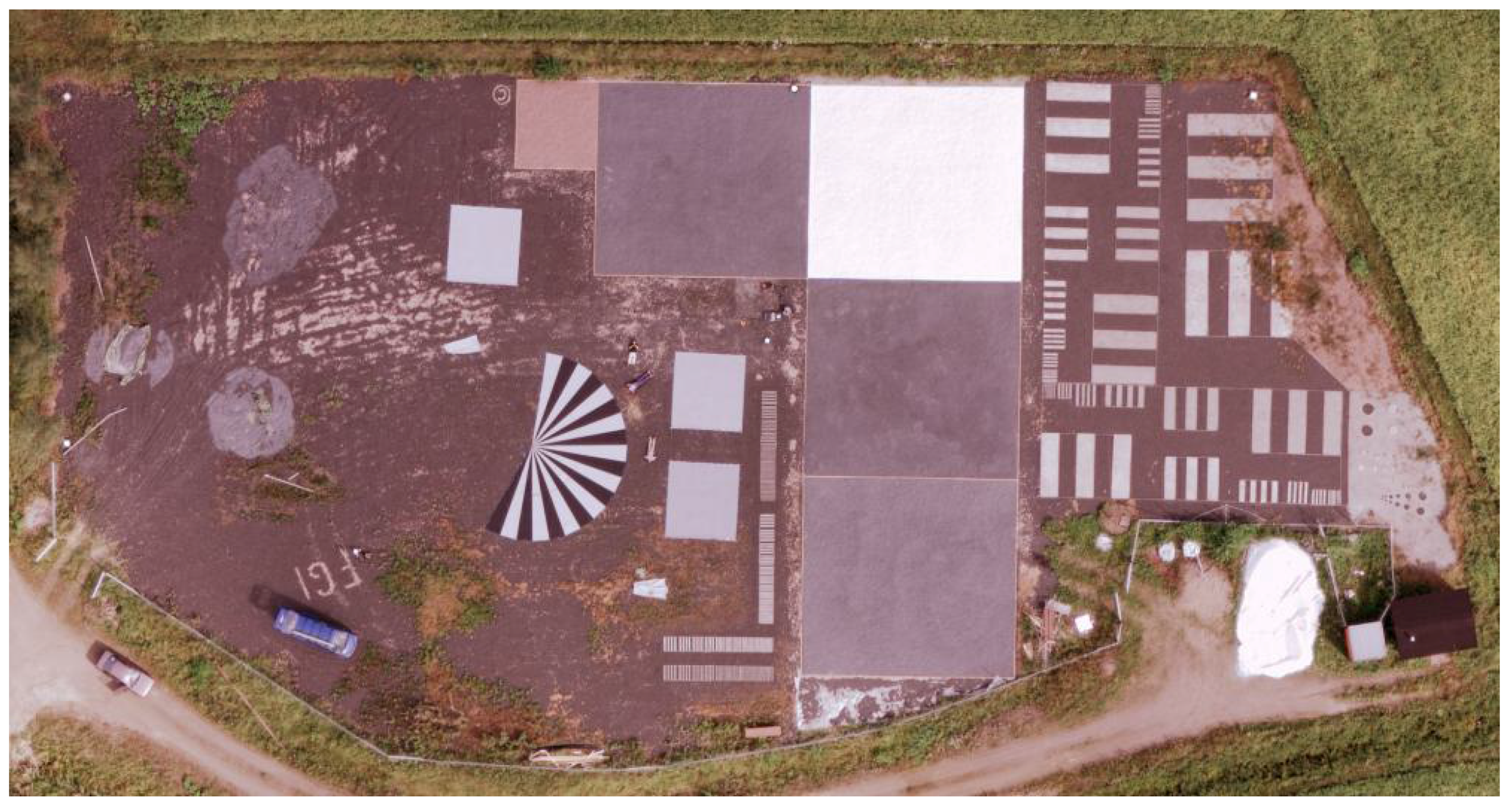
- Honkavaara, E.; Peltoniemi, J.; Ahokas, E.; Kuittinen, R.; Hyyppä, J.; Jaakkola, J.; Kaartinen, H.; Markelin, L.; Nurminen, K.; Suomalainen, J. A permanent test field for digital photogrammetric systems. Photogramm. Engin. Remote Sens. 2008, 74, 95–106. [Google Scholar] [CrossRef]
- Martínez, L.; Arbiol, R. ICC experiences on DMC radiometric calibration. In Proceedings of the International Calibration and Orientation Workshop EuroCOW 2008, Castelldefels, Spain; January 30-February 1, 2008. [Google Scholar]
- Arbiol, R.; Martinez, L. ICC-Banyoles 2008 campaign in the framework of EuroSDR radiometry project. In Project description and preliminary results. In Proceedings of the International Geomatics Week, Barcelona, Spain; March 3-5, 2009. [Google Scholar]
- Cramer, M.; Haala, N. DGPF project: Evaluation of digital photogrammetric aerial bases imaging systems—overview and results from the pilot centre. In Proceedings of the ISPRS Hannover Workshop 2009, Hannover, Germany; June 2-5, 2009. [Google Scholar]
- Berk, A.; Anderson, G.P.; Bernstein, L.S.; Acharya, P.K.; Dothe, H.; Matthew, M.W.; Adler-Golden, S.M.; Chetwynd, J.H., Jr.; Richtsmeier, S.C.; Pukall, B.; Allred, C.L.; Jeong, L.S.; Hoke, M.L. MODTRAN4 radiative transfer modeling for atmospheric correction. In Proceedings of the SPIE Conference on Optical Spectroscopic Techniques and Instrumentation for Atmospheric and Space Research III, Denver, CO, USA, July 1999; Vol. 3756, pp. 348–353.
- Vermote, E.F.; Tanré, D.; Deuzé, J.L.; Herman, M.; Morcrette, J.-J. Second simulation of the satellite signal in the solar spectrum, 6S: An overview. IEEE Trans. Geosci. Remot. Sens. 1997, 35, 675–686. [Google Scholar] [CrossRef]
- Chavez, P.S., Jr. Image-based atmospheric corrections—revisited and improved. Photogramm. Engin. Remote Sens. 1996, 62, 1025–1036. [Google Scholar]
- Smith, G.M.; Milton, E.J. The use of the empirical line method to calibrate remotely sensed data to reflectance. Remote Sens. 1999, 20, 2653–2662. [Google Scholar] [CrossRef]
- Richter, R. A spatially adaptive fast atmospheric correction algorithm. Int. J. Remote Sens. 1996, 17, 1201–1214. [Google Scholar] [CrossRef]
- Gao, B.-C.; Montes, M.J.; Davis, C.O.; Goetz, A.F.H. Atmospheric correction algorithms for hyperspectral remote sensing data of land and ocean. Remote Sens. Environ. 2009. In press. [Google Scholar] [CrossRef]
- Le Bris, A.; Boldo, D. Extraction of land cover themes from aerial ortho-images in mountainous areas using external information. Photogramm. Rec. 2009, 23, 287–404. [Google Scholar] [CrossRef]
- Richter, R.; Schläpfer, D. Geo-atmospheric processing of airborne imaging spectrometry data. Part 2: Atmospheric/Topographic Correction. Int. J. Remote Sens. 2002, 23, 2631–2649. [Google Scholar] [CrossRef]
- Hadjimitsis, D.G.; Clayton, C.R.I; Hope, V.S. An assessment of the effectiveness of atmospheric correction algorithms thorough the remote sensing of some reservoirs. Int. J. Remote Sens. 2004, 25, 3651–3674. [Google Scholar] [CrossRef]
- Biesemans, J.; Sterckx, S.; Knaeps, E.; Vreys, K.; Adriaensen, S.; Hooyberghs, J.; Meuleman, K.; Kempeneers, P.; Deronde, B.; Everaerts, J.; Schläpfer, D.; Nieke, J. Image processing workflows for airborne remote sensing. In Proceedings of the 5th EARSeL Workshop on Imaging Spectroscopy, Bruges, Belgium, April 23-25, 2007.
- Madani, M. Todays orthophoto production – The business model. In Photogrammetric Week ´07; Fritsch, D., Ed.; Wichmann Verlag: Heidelberg, Germany, 2007; pp. 269–176. [Google Scholar]
- Walker, S. New features in Socet Set®. In Photogrammetric Week ´07; Fritsch, D., Ed.; Wichmann Verlag: Heidelberg, Germany, 2007; pp. 35–40. [Google Scholar]
- Internet pages of the OrthoVista software:. http://www.orthovista.com/ (accessed August 11, 2009).
- Chandelier, L.; Martinoty, G. Radiometric aerial triangulation for the equalization of digital aerial images and orthoimages. Photogramm. Eng. Remote Sens. 2009, 75, 193–200. [Google Scholar] [CrossRef]
- Becker, S.; Haala, N.; Honkavaara, E.; Markelin, L. Image restoration for resolution improvement of digital aerial images: a comparison of large format digital cameras. In International Archives of Photogrammetry, Remote Sensing and Spatial Information Sciences, Proceedings of the ISPRS Commission I Symposium, Marne-la-Vallée, Paris, France, July 4-6, 2006. 36(A1).
- Cramer, M. The EuroSDR approach on digital airborne camera calibration and certification. In International Archives of the Photogrammetry, Remote Sensing and Spatial Information Sciences, Proceedings of the XXI ISPRS Congress, Commission IV, Beijing, China, July 3-11, 2008. 37(B4).
- Internet pages of the ISPRS. http://www.isprs.org (accessed August 11, 2009).
- Internet pages of the CEOS. http://www.ceos.org (accessed August 11, 2009).
- Internet pages of the EUFAR. http://www.eufar.net (accessed August 11, 2009).
- Stensaas, G.L. U.S. Geological survey digital aerial mapping camera certification and quality assurance plan for digital imagery. In Photogrammetric Week ´07; Fritsch, D., Ed.; Wichmann Verlag: Heidelberg, Germany, 2007; pp. 107–116. [Google Scholar]
- Kresse, W. Standardization in photogrammetry and remote sensing. In International Archives of the Photogrammetry, Remote Sensing and Spatial Information Sciences, Proceedings of the XXI ISPRS Congress, Commission IV, Beijing, China, July 3-11, 2008. 37(B4).
- Internet pages of ISO/TC 211. http://www.isotc211.org (accessed August 11, 2009).
© 2009 by the authors; licensee MDPI, Basel, Switzerland. This article is an open access article distributed under the terms and conditions of the Creative Commons Attribution license (http://creativecommons.org/licenses/by/3.0/).
Share and Cite
Honkavaara, E.; Arbiol, R.; Markelin, L.; Martinez, L.; Cramer, M.; Bovet, S.; Chandelier, L.; Ilves, R.; Klonus, S.; Marshal, P.; et al. Digital Airborne Photogrammetry—A New Tool for Quantitative Remote Sensing?—A State-of-the-Art Review On Radiometric Aspects of Digital Photogrammetric Images. Remote Sens. 2009, 1, 577-605. https://doi.org/10.3390/rs1030577
Honkavaara E, Arbiol R, Markelin L, Martinez L, Cramer M, Bovet S, Chandelier L, Ilves R, Klonus S, Marshal P, et al. Digital Airborne Photogrammetry—A New Tool for Quantitative Remote Sensing?—A State-of-the-Art Review On Radiometric Aspects of Digital Photogrammetric Images. Remote Sensing. 2009; 1(3):577-605. https://doi.org/10.3390/rs1030577
Chicago/Turabian StyleHonkavaara, Eija, Roman Arbiol, Lauri Markelin, Lucas Martinez, Michael Cramer, Stéphane Bovet, Laure Chandelier, Risto Ilves, Sascha Klonus, Paul Marshal, and et al. 2009. "Digital Airborne Photogrammetry—A New Tool for Quantitative Remote Sensing?—A State-of-the-Art Review On Radiometric Aspects of Digital Photogrammetric Images" Remote Sensing 1, no. 3: 577-605. https://doi.org/10.3390/rs1030577