Proximity Warning and Excavator Control System for Prevention of Collision Accidents


1
Department of Civil and Environmental Engineering, Hanyang University, Seoul 04763, Korea
2
Research and Development Center, Youngshine, Gyeonggi-do 13487, Korea
*
Author to whom correspondence should be addressed.
Sustainability 2017, 9(8), 1488; https://doi.org/10.3390/su9081488
Submission received: 26 July 2017
/
Revised: 18 August 2017
/
Accepted: 20 August 2017
/
Published: 22 August 2017
(This article belongs to the Special Issue Management Strategies and Innovations for Sustainable Construction)
Abstract
:Construction is a hazardous industry in which accidents occur frequently. Occupational accidents at construction sites are a serious public health issue in Korea. Construction site conditions often create dangerous situations by requiring workers and heavy equipment to work in close proximity to each other. In 2015, approximately 11% (46) of the 437 occupational fatalities in the construction industry in Korea resulted from workers colliding with objects or equipment. In this paper, we present a proximity warning system developed to address this issue and enhance safety at construction sites. The proposed technology functions in real time to alert workers and equipment operators of hazardous proximity situations. Also, when the radio frequency identification (RFID) sensor detects an approaching worker, the main board instantly shuts down the excavator for the prevention of accident. This system contains an RFID tag, RFID reader, alarm device, camera, a display device (the Around View Monitor), and excavator control technology. A field test demonstrated successful performance of the proposed system. It is widely applicable in small construction fields alongside excavators and other equipment because this system does not require additional communication infrastructure, such as servers.
1. Introduction
Occupational injuries from the construction field are a global public health issue, whereas the construction sector is a hazardous industry in which occupational accidents occur most frequently around the world [1]. Usnar and Sut [2] confirmed that from 2000 to 2005 in Turkey, occupational fatalities of the construction industry were much higher than in any other industry. According to Fabiano et al.’s [3] analysis from 2000 to 2004, the building industry is one of the highest risk sectors in Italy. Similarly, in Korea, an occupational accident is an important issue. Mortality rates of the construction field remained the highest among all the other economic sectors from 2011 to 2015 [4].
Generally, a construction site involves personnel, equipment, and materials performing multiple tasks. The equipment and workers perform continuous dynamic activities in a specific space. At times, the construction equipment operates in dangerously close proximity to workers. Such conditions can lead to collisions between workers and construction equipment, incurring the risk of personal injuries. In addition, construction equipment can be damaged in collision accidents. It has been shown that the proximity of workers to heavy equipment is a primary safety problem in construction [5]. Many of these accidents are caused by visibility problems of equipment operators [6]. Much research has investigated real-time safety technology to reduce or prevent safety accidents at construction sites [7,8]. Fosbroke [9] identified various factors leading to contact collisions at construction sites. Zhu et al. [10] proposed a technique that could improve construction site safety by predicting the movements of onsite workers and mobile equipment. Lee et al. [11] developed a radio frequency identification (RFID)-based real-time locating system (RTLS) for construction safety management. Teizer [12] tested construction site applications of magnetism-based proximity detection and alarm technology for safe heavy equipment operation. Seo et al. [13] proposed computer vision techniques to improve construction safety and health monitoring.
The purpose of the current research is to develop proximity detection and control system for prevention of collision accidents caused by excavators, a major type of construction equipment. The proposed system utilizes RFID technology and the Around View Monitor (AVM) to detect the approach of workers and alert them to dangerous situations using an alarm device. Also, the technology shuts down the excavator automatically when it is necessary. The rest of this paper is organized as follows. First, it reviews the literature on existing real-time proximity detection and alert technologies for prevention of collision accidents. Second, it describes the motivation and purpose for this paper. Third, it describes the configuration and functions of the developed system. Finally, the methodology and results of the system performance test are presented.
2. Research Trend
2.1. Review of Proximity Warning Technology
In 1998, the Mine Safety and Health Administration (MSHA) proposed a rule change to install a proximity warning system on mine equipment to prevent collision accidents [14]. Researchers at the National Institute for Occupational Safety and Health (NIOSH) evaluated several proximity warning technologies that can be used to detect the presence of an obstacle and provide an alert to the equipment operator [15,16]. The study was conducted to verify the feasibility of commercially available proximity warning technologies that could be applied to dump trucks in a mine. The proximity warning systems used in the test included radar, radio frequency identification (RFID), and global positing system (GPS) technologies. Researchers at the NIOSH concluded that these proximity warning systems showed potential for reducing collision accidents involving equipment at the mine site. NIOSH developed a proximity warning system called HASARD (hazardous area signaling and ranging device) to reduce collision accidents with heavy mining equipment [17]. The HASARD system employs magnetic sensing technology and is composed of two parts, a transmitter and a receiver. The transmitter produces a magnetic field at the equipment areas, and the worker-mounted receivers detect the magnetic field strength and alert workers near the hazardous equipment.
GPS has also been used to prevent equipment-related collision accidents in underground or surface mining. For collision accident prevention between workers and heavy equipment in mines, Nieto [18] developed a GPS-based proximity warning system that employed a combination of GPS, a wireless networking system, and a 3D graphics display interface. It used GPS technology to track the positions of the heavy equipment and automatically alerted the operators to equipment proximity hazards. To achieve this, reliable GPS units and onboard computer systems were mounted on the heavy equipment. The system was also able to generate 3D digital maps of the work area during equipment operation. The system used the 3D mapping system to generate a 3D model of the heavy equipment based on location information (xyz coordinates) of the GPS device. The operator could visually monitor the surrounding area for dangerous situations through the screen device installed on the equipment. Nieto and Dagdelen [19], and Ruff and Holden [20] showed that GPS-based proximity warning systems have the potential to significantly reduce collision accidents. Through additional research, Nieto et al. [21] developed a new proximity warning system that combined GPS with a transmission-locking mechanism. This mechanism [21] can automatically prevent equipment from moving when a high risk of collision accident is detected. For timely warnings about approaching equipment at long distances (10–100 m), Sabniveesu et al. [22] developed a GPS-based warning system integrated with wireless communications that operated in an ad-hoc mode. In addition, they designed a cloud-based data-logging system to facilitate the collection of long-term data about locations of several pieces of equipment. They evaluated this collision warning system for feasibility through a field test. Recently, GPS devices together with wireless communication technology are increasingly being used for prevention of collision accidents with heavy equipment and for safety management.
Proximity warning systems using GPS and RF technology have also been applied at construction sites. Oloufa et al. [23] developed a situational awareness system for construction equipment using GPS, wireless communications, and web-based technologies. For construction equipment tracking and collision avoidance, researchers designed a system that transmits position data in real time from the GPS receivers mounted on the equipment. Lee et al. [24] developed a safety monitoring system to reduce fatal accidents at a construction site. The system was composed of a hybrid sensing device (including ultrasonic and infrared sensors) for detecting the workers, a transmitter and repeaters for sending the detection data to a receiver, a receiver connected to the main computer, and software for data analysis. The monitoring system operated in three stages: (1) detecting workers’ approaches; (2) acquiring and transmitting data; and (3) managing worker safety. This system was intended to reduce fatal accidents on the construction site. Chae and Yoshida [25] designed an RFID-based monitoring system for prevention of accidents involving heavy equipment, such as excavators, cranes, and trucks. Implementation of the system required a communication technology and a hand-held device to transmit an alarm signal that could be confirmed by the workers. To prevent falling and proximity accidents at construction sites, Wu et al. [26,27] investigated the application of ZigBee/RFID sensor network technology. In a similar study, Yang et al. [28] proposed a safety management system based on a ZigBee-enabled wireless sensor network and RFID technology. Kelm et al. [29] proposed an RFID-based automatic identification system that allows compliance checking of the personal protective equipment (PPE) worn by workers at construction sites. The use of PPE is important to protect the health and safety of construction workers. This system can automatically check that the workers are wearing the necessary PPE components before starting tasks in the work area.
Some researchers have proposed preliminary testing methods to evaluate the reliability of various proximity warning systems for construction site applications. Teizer et al. [5] presented a radio frequency (RF)-based proximity warning technology and evaluated its performance through a field experiment. The system used RF technology at a very-high frequency (VHF) near 700 MHz, and it was composed of equipment protection units (EPUs) and personal protection units (PPUs). The EPUs were installed inside the equipment, and the PPUs were deployed on the workers. Each EPU transmitted signals in a radial manner, and each PPU estimated the distance based on the intensity of the RF signal. Once the user-specified signal strength was met, warning signals (including auditory, visual, and vibrating alarms) were emitted in real time. Through a field test, they demonstrated that this system could be used to prevent collision accidents on construction sites. Marks and Teizer [30] presented a testing method and demonstrated its ability to evaluate the reliability and effectiveness of RF-based proximity warning systems in construction environments. Similarly, Choe et al. [31] proposed a method to evaluate ultrasonic and radar-based warning technologies. Teizer [12] evaluated the reliability and effectiveness of a magnetic field proximity warning system in a harsh construction environment.
2.2. Summary of Previous Research
Over the past several years, studies of proximity warning systems have been performed by many research groups [7,8]. These researchers argued that the appropriate use of various sensor technologies could be effective in preventing accidents during dangerous proximity situations. Proximity warning technologies implemented at various industry sites provide alerts to workers and equipment operators in real time when a dangerous proximity situation is occurring. Most proximity warning system consists of sensors (such as, radar, RFID, and GPS) mounted on the equipment that detect the presence of obstacles, and an alarm interface [21,32]. These systems can reduce collision accidents by alerting workers and equipment operators when equipment gets too close. However, many proximity warning technologies, such as RF and GPS, have unique limitations when deployed at a construction site, such as availability of signal, weight, size, power source, reliability, and price [16,33,34]. For example, radar sensors are not suited to use in harsh environments that include obstacle objects that can trigger false alarms [34,35]. In an RF-based warning system, transmitters and receivers must be installed on all workers and equipment to achieve a proper effect [5]. GPS offers many benefits, but it has the disadvantage of being expensive [21,23]. Thus, these proximity warning systems need further testing and practical implementation strategies before they can be widely used at industry sites. Further, the proximity warning systems for various construction equipment types must be determined based on equipment sizes and characteristics. Table 1 provides a qualitative overview of the characteristics of sensing technology for the proximity warning system.
3. Research Motivation and Scope
Past research has shown the applicability of RFID technology for accident prevention [25,26,27,28,29,37]. The RFID system is a technology that identifies objects using radio waves of different frequencies. Generally, an RFID system consists of an RFID tag and an RFID reader, and it has the following advantages. (1) An RFID system requires little maintenance; (2) It can easily be designed to meet user requirements (including cost and size); (3) It can read multiple tags at a high rate; (4) It is unlikely to malfunction due to the positive nature of tag detection; (5) It is easy to install and apply at construction sites. For these reasons, RFID technology is ideal for use at harsh construction sites. However, it does not provide information for visually distinguishing objects. This limitation can be overcome by combining it with video technologies. A display device can provide visual information to equipment operators, making proximity warning systems more effective. However, the operator must constantly observe the monitor to check for hazardous situations. In addition, it takes time to control the equipment after recognizing a dangerous situation. Therefore, operators could be unable to avoid dangerous situations. Also, it is necessary to develop a technology that can recognize proximity hazards and control the equipment in real time. The aim of the current research is to develop and test a real-time excavator control system using RFID and an AVM to enhance safety at construction sites. AVM systems have been developed by many automobile companies as driver assistance systems [38]. An AVM system is a technology that provides an operator with a 360° image of the surroundings.
4. Proximity Warning and Excavator Control System
4.1. System Concept
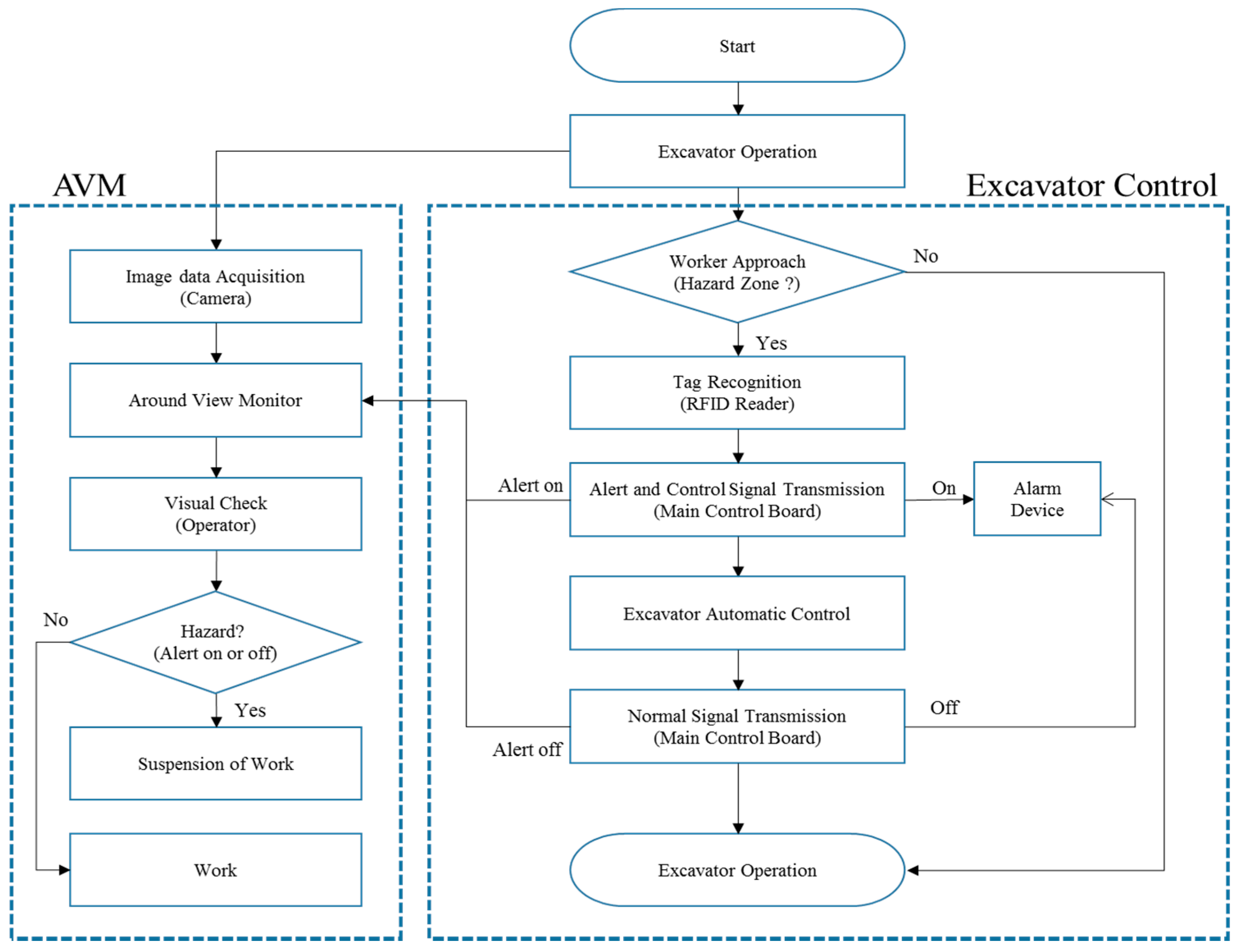
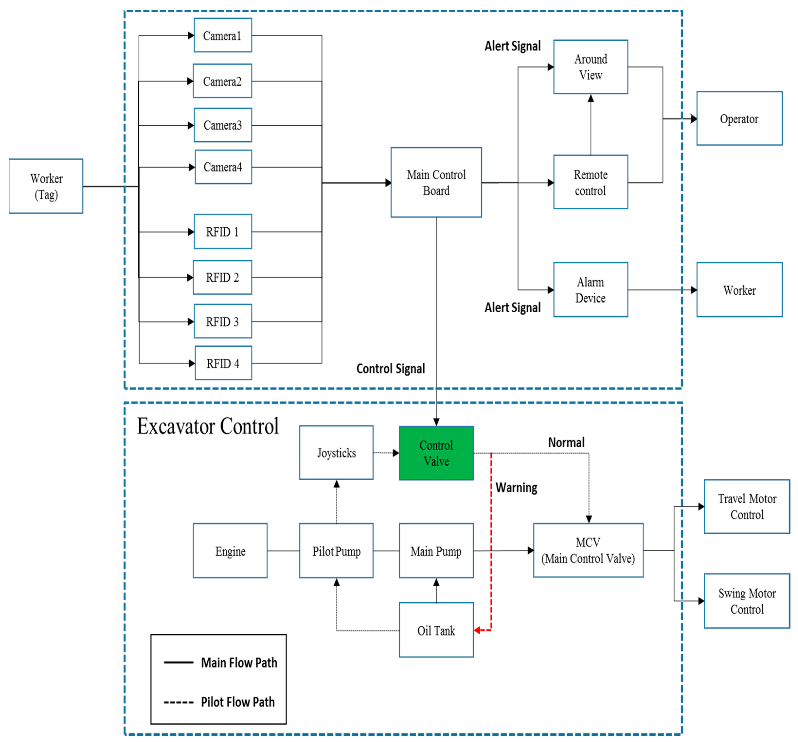
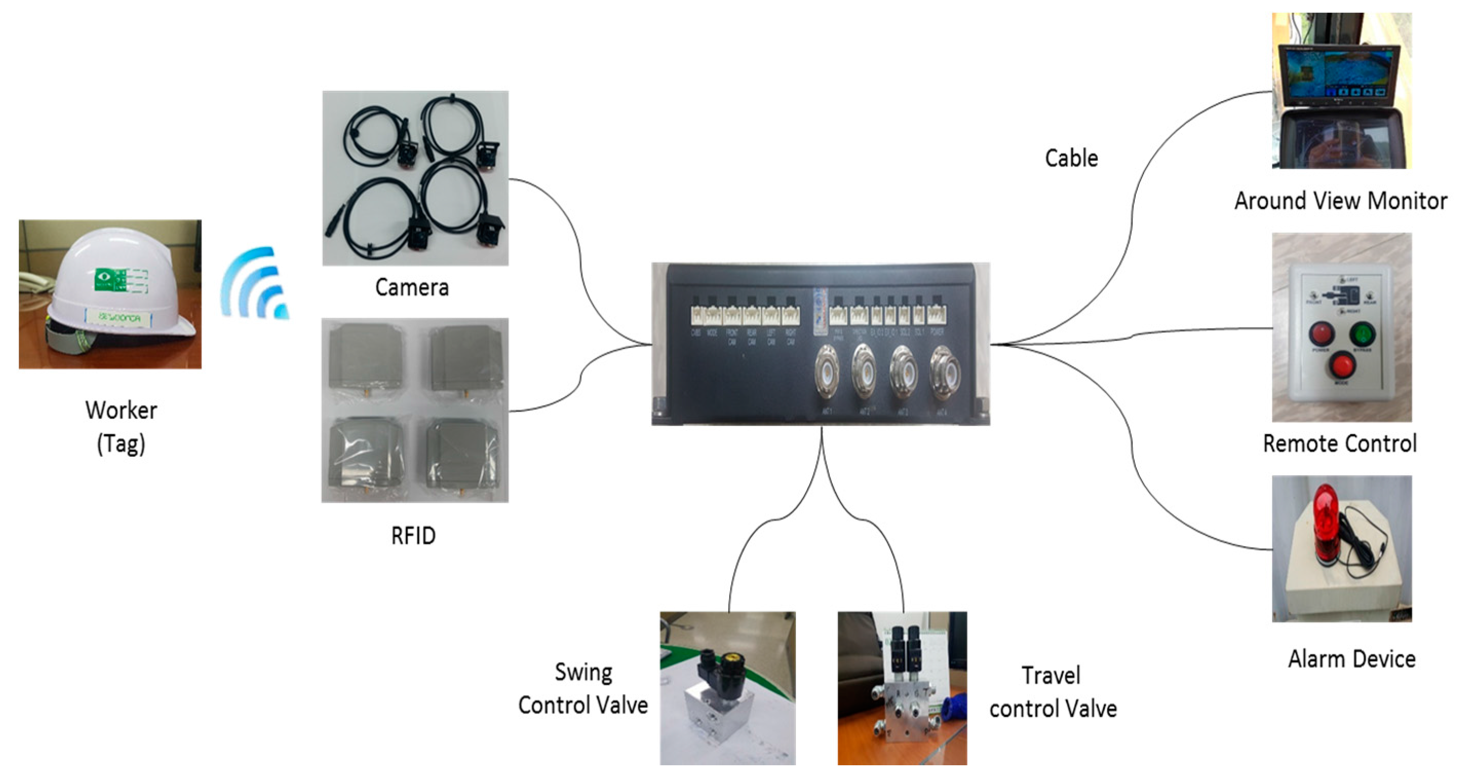
The proposed system involves three technologies: an AVM system for visual monitoring, an RFID system for automatic detection of workers, and an excavator control system for prevention of collision accidents. These technologies are combined in a real-time proximity warning and excavator control system called SEWOONDA. As shown in Figure 1, the camera and RFID antenna are mounted on the excavator to detect approaching workers. The AVM is mounted on the excavator cabin and provides a view of the surroundings. In addition, the AVM provides audible and visual warning information to the equipment operator if a hazard signal is received from the RFID antenna. The operator of the excavator can monitor the approach of a worker through the AVM. An RFID tag is deployed to each worker in the construction site. An RFID antenna is installed on the side or back of the excavator and emits radio frequency signals. The RFID antenna recognizes the RFID tags of workers approaching the excavator. A control valve is connected to the hydraulic valve of the excavator that controls the flow of oil for excavator operation. This valve can be used to automatically stop the excavator. All the functions of the SEWOONDA system are controlled by the main control board in real time. Figure 2 shows the entire operation scenario of the proposed system and Figure 3 shows a block diagram of the hardware. It is widely applicable in small construction fields alongside excavators and other equipment because this system does not require additional communication infrastructure, such as servers. Table 2 shows the main differences between the proposed technology and the conventional proximity warning system for preventing collision accidents. Further details of the proposed system are explained in the following subsections.
4.2. AVM System
AVM technology is the main technique for prevention of collision accidents adopted in advanced vehicle assistance systems [39]. Generally, an AVM system receives input images from multiple fisheye cameras mounted on the vehicle (front, rear, left, and right sides) in real time and processes them to display a top-view (360° surrounding views) image via a color screen. Figure 4 shows a general flowchart of the AVM system. A fish-eye lens typically creates radial distortion. To provide a top-view image from multiple fisheye cameras, the first step is to correct the radial distortion of the images. Generally, researchers have calibrated cameras using the polynomial model [40,41] and the FOV model [42] to correct for the radial distortion [43,44]. In the current study, we applied a radial distortion correction method based on the FOV model proposed by Park et al. [44]. Next, those corrected images must be projected onto a planar surface to obtain a 360° surrounding view image. For this process, we used a homography technique [45], which is the most common image processing technique to deform an image, and it is widely used in AVM systems [39,46,47].
After correcting for the distortion of the multiple fisheye images and registering all images on a planar surface via homography, the images must be combined to form a single image. We applied image-stitching technology [48] for this purpose. We developed an AVM system (including a display device, fisheye cameras, and a remote control) that is able to provide the top-view image of for the excavator’s surroundings using existing technologies (Figure 5, Figure 6 and Figure 7).
4.3. RFID System
For the proposed system, we selected commercial RFID technology as the real-time worker detection method. The RFID reader transmits detection signals to the main control board if tag recognition information is received from the RFID antenna. The RFID antenna is mounted on the side or back of the excavator, and the RFID reader is connected to the main control board. The tag is attached to workers who need to be detected in the working area. In this study, we used passive RFID tags with relatively low prices [49]. In general, passive tags can be read from distances up to 10 meters, but the read range depends on the frequency band and tag type [50]. Figure 8 shows an RFID antenna and bracket that were redesigned to be easily installed on an excavator. Table 3 lists the specifications of the RFID system. The alarm device is mounted on the excavator and provides both audible (speaker) and visual (LED) warning information when a detection signal is received from the main control board.
4.4. Excavator Control System
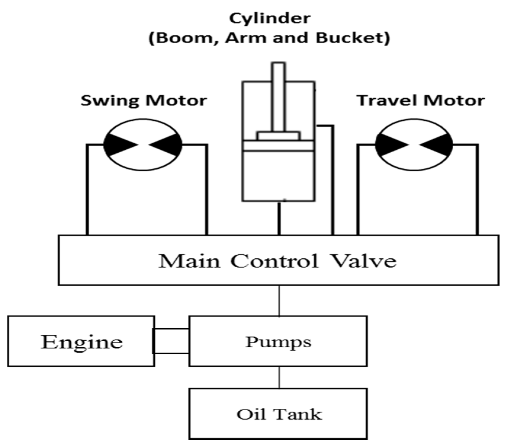
Generally, an excavator system consists of an engine, pumps, hydraulic valves, and actuators [51]. Figure 9 shows the configuration of a common excavator. The pumps are propelled by the engine, and they deliver the necessary fluid power to each actuator for operation. The hydraulic valves consist of the main control valve (MCV) and multiple on/off-type valves connected to each actuator. These valves are used to control the flow rate of the oil to control the output and speed of the actuator. The actuator acts to convert the oil pressure into mechanical work. For more information on excavator systems, please refer to the following paper [52].
The main issues when designing an excavator operation control system are to achieve (1) simple installation of the device, (2) automatic real-time control, and (3) economic effectiveness. In this study, we propose an automatic control method to prevent collision accidents, as described in Table 4. In an excavator system, the main flow rate supplied to each actuator is controlled by the spool of the main control valve, and the spool displacement is controlled by the pilot pressure via a joystick. It is possible to add a control valve between the joystick and the spool so that it allows the excavator to be stopped by shutting off the pilot flow, in the event of a hazard (Table 5). For this purpose, a control valve is designed, as described in Table 6. There are two types of control valves, a swing control valve, and a travel control valve. A solenoid valve is attached to each control valve, and it is operated via the main control board, as follows. (1) Normally, in the proposed system, the control valve is closed so that it works similarly to that of a conventional excavator system. (2) When the RFID system senses danger, such as when it detects approaching workers, the main control board transmits an electrical signal that allows the control valve to be opened so that the pilot oil flows to the oil tank instead of the MCV (spool). This restriction of main oil flow to the actuator stops the excavator’s operation.
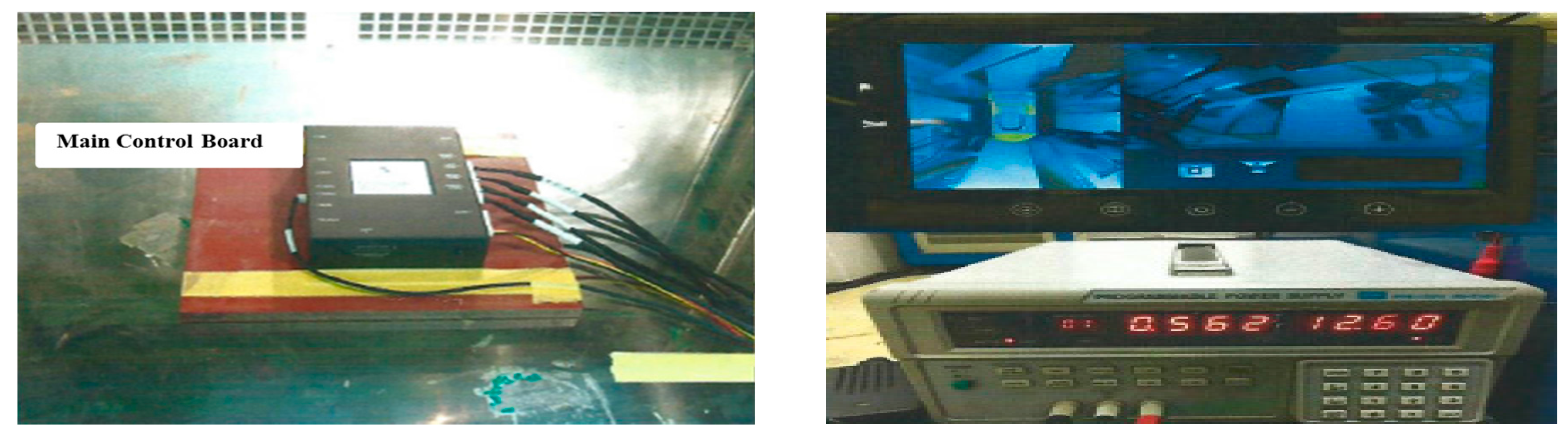
Finally, the main control board we developed to operate the system is shown in Figure 10. The main control board, RFID board, AVM board, and control board are included. Figure 11 shows an overview of this system. All of the communications in the proposed system are managed via the main control board, except for the communication that occurs between the RFID tag and the RFID antenna. A total of four cameras and four RFID antennas can be connected to the main control board. A safety supervisor can flexibly adapt the AVM system or RFID system according to their budget and work environment.
5. Experiments
This system was evaluated in several different experimental settings, executed to measure the reliability and effectiveness of the proximity warning and excavator control system for collision prevention between a worker and an excavator. Past research [30,31] has developed preliminary testing methods to evaluate various proximity warning systems for prevention of collision accidents. In this paper, we designed the experimental methods based on these test methods.
5.1. Temperature Cycle Test
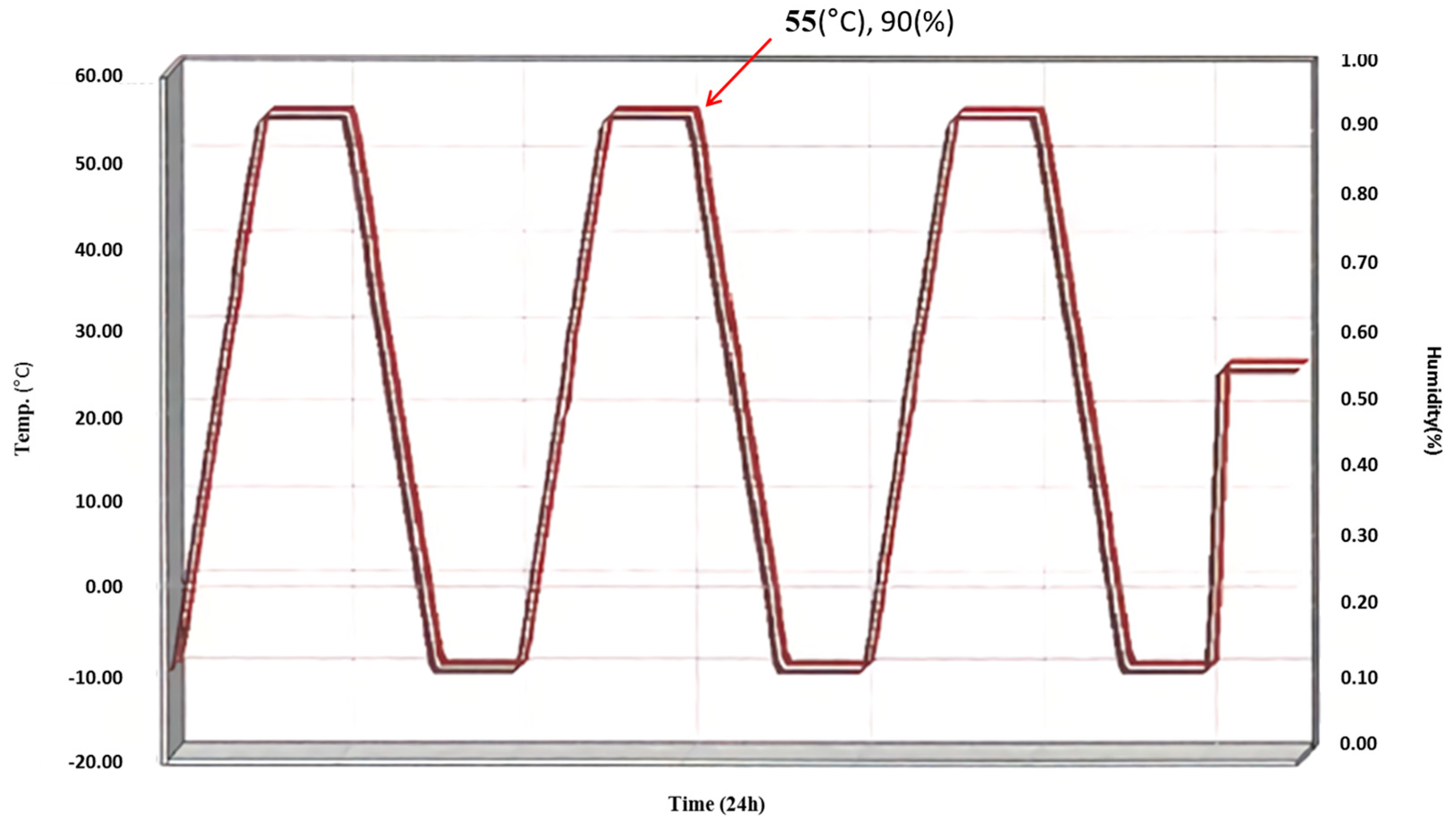
A temperature cycle test was conducted to evaluate if the system could resist cyclical temperature changes (low and high temperatures) within an air environment. The system was tested from Tmin = −10 °C to Tmax = 50 °C. After the temperature cycle test experiment was completed, the sample was allowed to stand at ordinary temperature for 2 h, and apply the rated voltage to confirm the function (normal operation). As a result of the test (Figure 12), the proposed system was confirmed to normal operate at −10 °C to 55 °C (relative humidity, 90%).
5.2. Reliability of AVM System
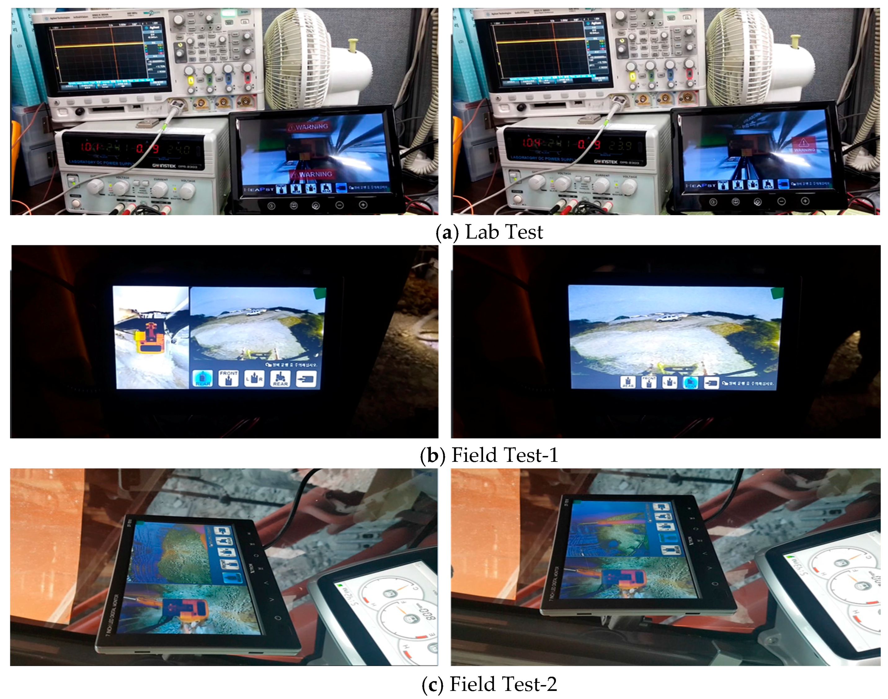
In this study, to evaluate the reliability of AVM system, we performed various experiments both at laboratory scale and in the actual field. In this AVM system, four fisheye cameras (front, right side, left side, and rear) and a display device have been integrated via a cable line. Operation of the AVM system has been tested for 24 h at laboratory scale and 1 h in the actual field. A pictorial view of laboratory scale working is demonstrated in Figure 13a–c. During the whole experiment, the AVM system worked properly. The AVM reliability test in actual field conditions is shown in Figure 13a–c. Again, during the observation time, the AVM system showed normal working. For both experiments, this AVM system continuously displayed without any distraction/distortion.
5.3. RFID Detection Area Test
In order to evaluate the RFID detection area and alarm alert, testing RFID proximity under different conditions is an essential part to measure its reliability. Therefore, to evaluate the proximity of the RFID system and alert ability of the alarm system, four different experiments were performed under different conditions. These experiments measured the performance of the system in terms of detection, under different operating and environment conditions. Each experiment is explained as follow.
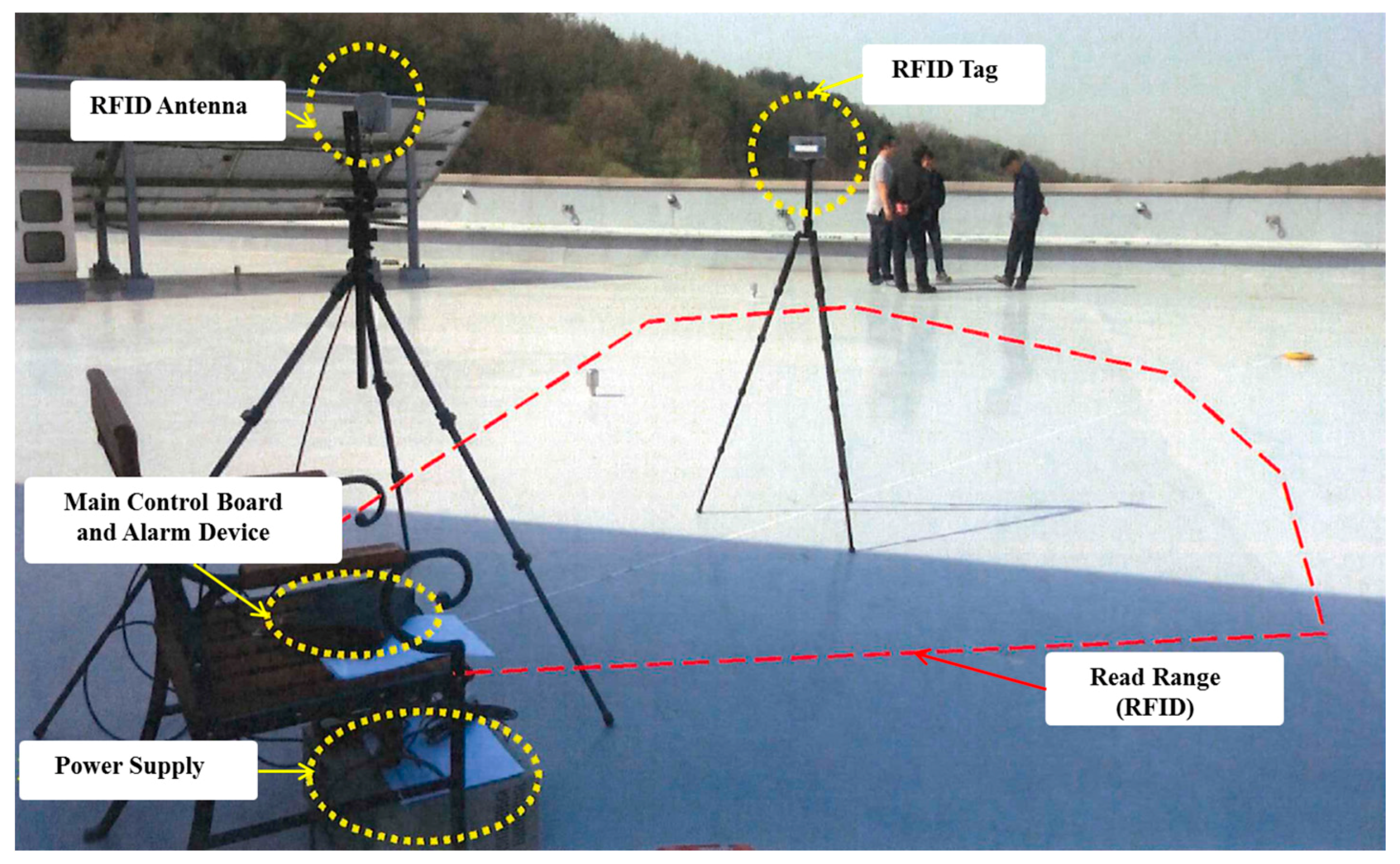
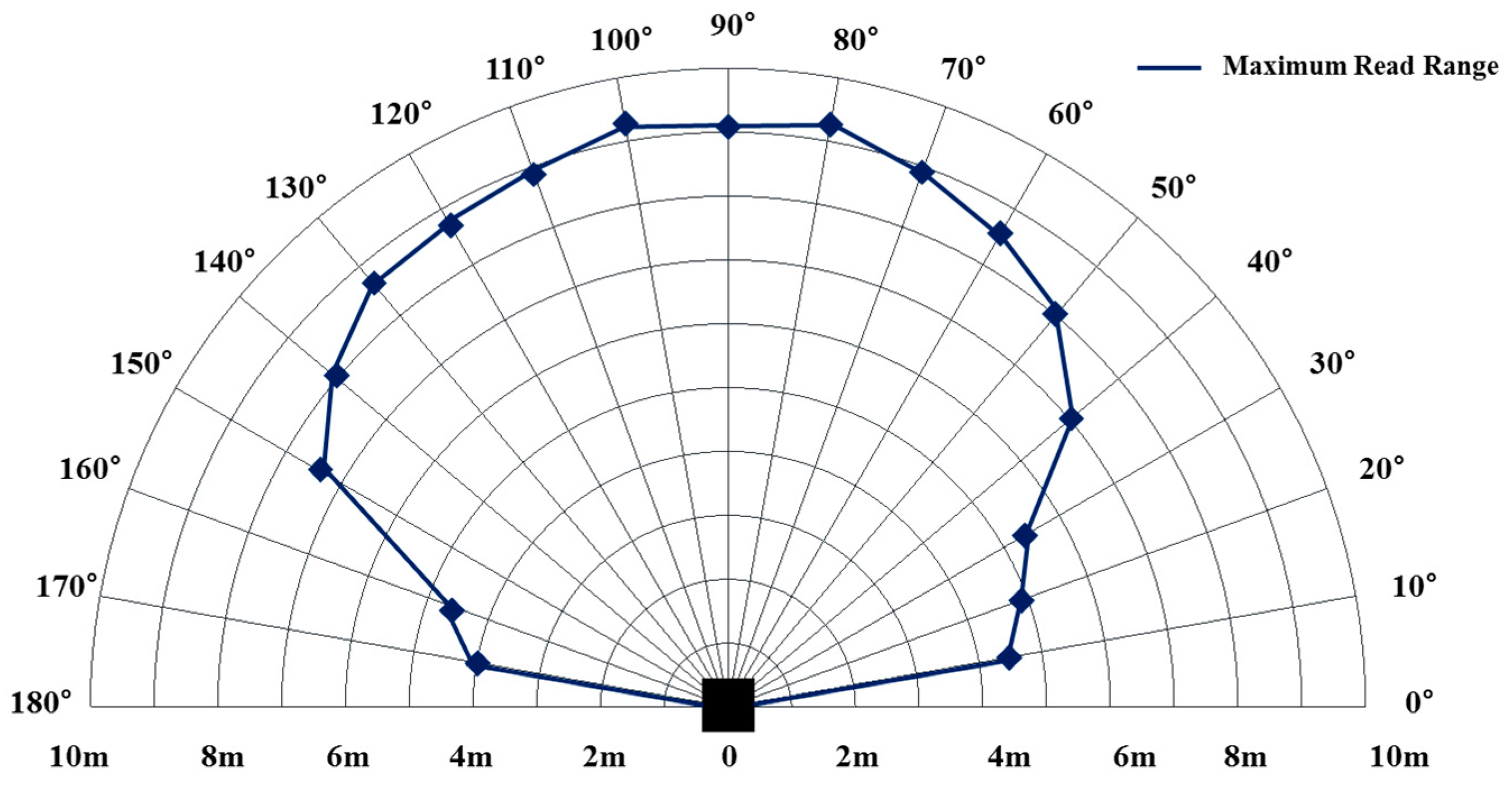
To evaluate the coverage area of RFID detection system, a test was performed by setting RFID antenna and tag perpendicular to the ground surface facing each other (Figure 14). Both antenna and tag were set at the same height (2.0 m) from the ground. The RFID antenna was attached with an alarm system and its position was fixed. In this experiment, the position of the RFID tag was changed while approaching towards the RFID antenna front side straight along radial lines. These radial lines were separated from each other at a constant interval of 10°. Every time the RFID tag approached the detection range of the RFID antenna in the case of each radial line, the attached alarm system was activated. As the alarms were activated, the distance was measured, giving the proximate distance at a particular angle to the RFID antenna. The same procedure was repeated 10 times for each angle. In this test scenario, it was expected that the RFID system enables maximum detection area performance. The alert distance measurement provided with the proximity coverage area of RFID detection, which has been plotted on coverage area graph, is shown in Figure 15.
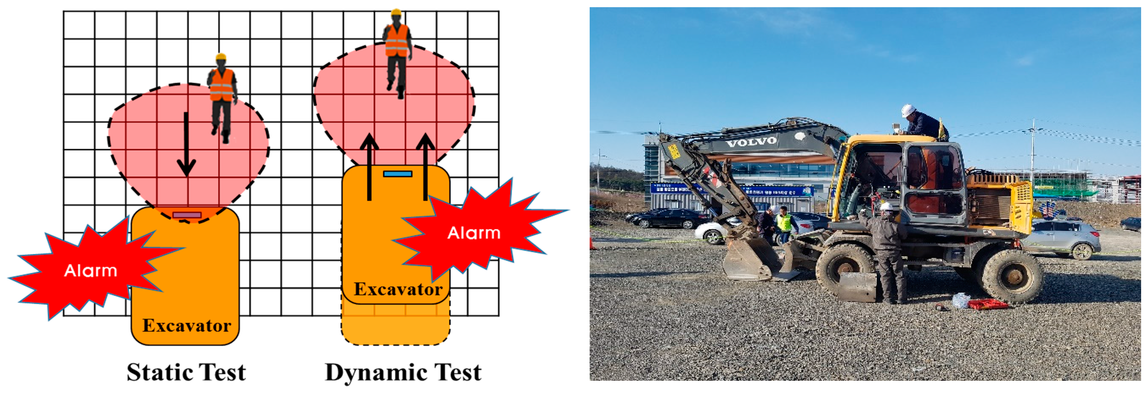
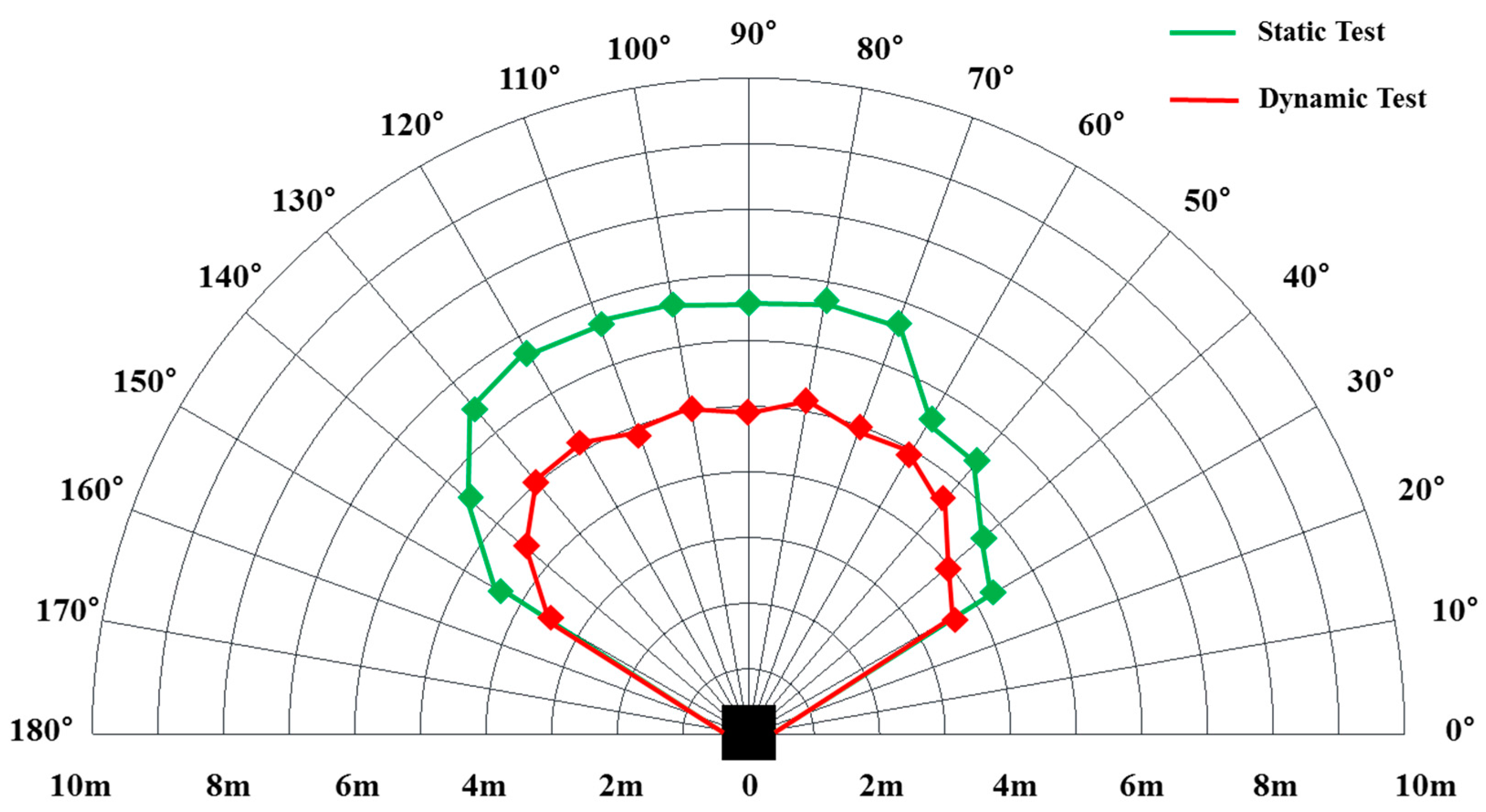
The second experiment was performed as a static test (immobile excavator) to evaluate the variation in the detection range of the RFID system. In this experiment, the RFID antenna was installed on an excavator and the tests were performed under the condition that the excavator remained immobile while the worker approached the excavator. Again, in this experiment, the number of repetitions was ten. Another experiment was performed with dynamic conditions (moving excavator). In this test, a RFID tagged worker stood static at his fixed position while the RFID antenna-installed excavator approached the same worker. This test was also performed for ten times. Figure 16 shows the experimental conditions of both the static and dynamic tests. The boundaries of the detection areas are the alarm activation distances, for both cases. Static and dynamic tests are demonstrated in Figure 17 as RFID detection area.
Table 7 summarizes the maximum range test, static test, and dynamic tests as explained earlier. In the case of maximum range test, the minimum proximity distance (4.0 m) was detected for an angle of 170°, while maximum coverage range distance was detected at angles of 80° and 100°. The minimum detection was found to be 4.3 m at an angle of 30° for the static test. The maximum detection distance for the static test was 6.5 m at 80°. For the dynamic testing, the minimum and maximum detection distances were 3.6 m and 5.2 m, at angles of 140° and 80°, respectively. Based on the results obtained from the maximum range test, and static and dynamic tests, it is concluded that the minimum safe zone is 3 or 4 m.
The proposed RFID detection system has significant importance in enhancing the safety at a construction site, especially for the workers working in the vicinity of an operational excavator. Therefore, it is of prime importance to check the false positivity and false negativity of the proposed RFID detection system. These tests were performed in outside conditions, Figure 18. The result of these tests demonstrated no false alerts (including nuisance alarms) during any of the 30 trials run at 3 m detection zone, summarized in Table 8. From empirical evidence, it follows that the reliable detection distance corresponds to 3.0 m.
5.4. Total System Test
Finally, we performed the field experiment to verify the applicability of the total system (including AVM, RFID, and excavator control system) on a construction site. The test procedures are:
- (1)
- Install proximity warning and excavator control system to equipment (4-RFID antennas, main control board, an alarm device, 4-fisheye cameras, and display device) and workers (RFID tag), Figure 19. Depending on the equipment type and field conditions, the detection area can be changed by adjusting the installation position and angle of the RFID antenna.
- (2)
- Connect the control block between the joystick of the excavator and the MCV.
- (3)
- Connect all devices to the main control board with cables.
- (4)
- Allow workers to approach RFID antennas or fisheye cameras at a slow pace over long distances.
- (5)
- Ensure that the system is activated and the excavator stops operating.
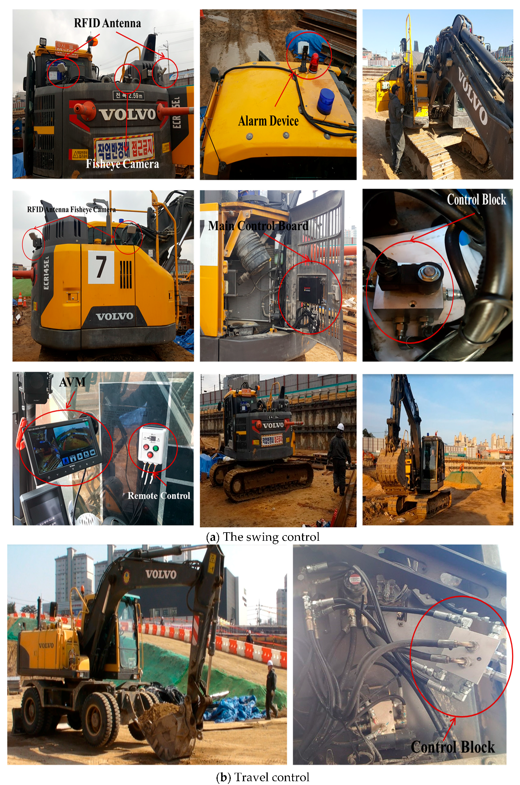
In this test, wheel type and track-type excavators were used. Figure 20 shows the configuration used for this test. The alarm device and control block were activated correctly when a worker with a RFID tag entered the RFID antenna’s detection range. Additionally, the system did not work when the person was outside the detection range of the RFID antenna. When a warning signal was transmitted from the main control board, a visual alarm appeared on the display device. Depending on the mode selected by the remote control, the image view was automatically switched to the front, left/right, or rear. This display device provided the operator with more detailed information, enabling them to better identify a proximity situation. A swing control and travel control have also been successfully tested. The excavator was automatically stopped (control signal) and operated (normal signal) when the control block was activated by the main control board.
6. Limitations and Future Research
This study presents a proximity warning and excavator control system to prevent collision accidents at construction sites. In this paper, we also evaluated the applicability of the proposed system. A limitation of this system is: as this system detects RFID tags in its coverage range, it suddenly halts the excavator, causing additional vibration in the excavator. This can be an inconvenience to the operator. In order to solve this problem, we set the response time of the present system at a delay of 1 second, which enables the system to minimize abrupt braking of the excavator. The delayed time setting helped to reduce the problem of sudden excavator stoppage. This delay time was decided after discussing with the excavator operator. However, the vibration problem is highly dependent on the feelings of the operator and can vary from person to person. So, detailed research is needed for delay time settings with the synchronization of the mechanical equipment and human vibration feeling effects.
7. Conclusions
In this paper, the proximity warning and control system has been developed for the prevention of collision accidents around an excavator. RFID and AVM systems for detection or monitoring of workers and an excavator control system are the main functions of the proposed system. The RFID technology was selected to detect the hazard proximity situation in real-time. However, the RFID does not provide visual information that can distinguish workers from harmless objects. To overcome such a drawback, an AVM system was used. A visual method of monitoring allows an equipment operator to check the surrounding hazards precisely. In addition, authors proposed an automatic excavator control method to prevent collision accidents. Several experiments were performed to verify the applicability and reliability of the system. Firstly, we performed a temperature cycling test which confirmed the operating temperature from −10 °C to 55 °C with up to 90% relative humidity for the normal operation of this system. Secondly, the reliability of the AVM system was tested in lab and field environments for long periods of operation. Another experiment was performed to identify the range of the RFID detection area under static and dynamic conditions. We also performed false alarm tests at a construction site, resulting in the determination of a 3.0 m safety zone around the working excavator. Final experiments were performed for evaluation of the proximity warning and excavator control systems at a construction site. In this test, the system proved its competence for detecting the presence of any hazardous proximity situations, and this system proved itself efficient in reducing collision accidents at construction sites.
Acknowledgments
This research was supported by the Research Grant from Youngshine Co. Ltd through the Korea Agency for Infrastructure Technology Advancement funded by the Ministry of Land, Infrastructure and Transport of the Korean government(Project No. 17TBIP-C111691-02).
Author Contributions
Byung wan Jo and Yun sung Lee co-designed and wrote the manuscript; Jung Hoon Kim collected the related data; Do-Keun Kim and Pyung-Ho Choi provided the data.
Conflicts of Interest
The authors declare no conflict of interest.
References
- Zhou, W.; Whyte, J.; Sacks, R. Construction safety and digital design: A review. Autom. Constr. 2012, 22, 102–111. [Google Scholar] [CrossRef]
- Unsar, S.; Sut, N. General assessment of the occupational accidents that occurred in Turkey between the years 2000 and 2005. Saf. Sci. 2009, 47, 614–619. [Google Scholar] [CrossRef]
- Fabiano, B.; Currò, F.; Reverberi, A.P.; Pastorino, R. A statistical study on temporary work and occupational accidents: Specific risk factors and risk management strategies. Saf. Sci. 2008, 46, 535–544. [Google Scholar] [CrossRef]
- Jo, B.W.; Lee, Y.S.; Kim, J.H.; Khan, R.M.A. Trend analysis of construction industrial accidents in Korea from 2011 to 2015. Sustainability 2017, 9, 1297. [Google Scholar] [CrossRef]
- Teizer, J.; Allread, B.S.; Fullerton, C.E.; Hinze, J. Autonomous pro-active real-time construction worker and equipment operator proximity safety alert system. Autom. Constr. 2010, 19, 630–640. [Google Scholar] [CrossRef]
- Ray, S.J.; Teizer, J. Computing 3D blind spots of construction equipment: Implementation and evaluation of an automated measurement and visualization method utilizing range point cloud data. Autom. Constr. 2013, 36, 95–107. [Google Scholar] [CrossRef]
- Zhou, Z.; Goh, Y.M.; Li, Q. Overview and analysis of safety management studies in the construction industry. Saf. Sci. 2015, 72, 337–350. [Google Scholar] [CrossRef]
- Skibniewski, M.J. Research trends in information technology applications in construction safety engineering and management. Front. Eng. Manag. 2015, 1, 246–259. [Google Scholar] [CrossRef]
- Fosbroke, D. Niosh reports! Studies on heavy equipment blind spots and internal traffic control. In Proceedings of the 2004 Roadway Work Zone Safety & Health Conference, Baltimore, MD, USA, 4 November 2004. [Google Scholar]
- Zhu, Z.; Park, M.-W.; Koch, C.; Soltani, M.; Hammad, A.; Davari, K. Predicting movements of onsite workers and mobile equipment for enhancing construction site safety. Autom. Constr. 2016, 68, 95–101. [Google Scholar] [CrossRef]
- Lee, H.-S.; Lee, K.-P.; Park, M.; Baek, Y.; Lee, S. Rfid-based real-time locating system for construction safety management. J. Comput. Civ. Eng. 2011, 26, 366–377. [Google Scholar] [CrossRef]
- Teizer, J. Magnetic field proximity detection and alert technology for safe heavy construction equipment operation, ISARC. In Proceedings of the 32nd International Symposium on Automation and Robotics in Construction, Oulu, Finland, 15–18 June 2015. [Google Scholar]
- Seo, J.; Han, S.; Lee, S.; Kim, H. Computer vision techniques for construction safety and health monitoring. Adv. Eng. Inf. 2015, 29, 239–251. [Google Scholar] [CrossRef]
- Mine Safety and Health Administration (MSHA). Safety standards for surface haulage—Proposed rule. In Federal Register; Mine Safety and Health Administration: Arlington, VA, USA, 1998; Volume 63. [Google Scholar]
- Ruff, T.M. Test Results of Collision Warning Systems for Surface Mining Dump Trucks; U.S. Department of Health and Human Services, Public Health Service, Centers for Disease Control and Prevention, National Institute for Occupational Safety and Health, Pittsburgh Research Laboratory: Pittsburgh, PA, USA, 2000. [Google Scholar]
- Ruff, T. Recommendations for Evaluating and Implementing Proximity Warning Systems on Surface Mining Equipment; U.S. Department of Health and Human Services, Public Health Service, Centers for Disease Control and Prevention, National Institute for Occupational Safety and Health, Spokane Research Laboratory: Spokane, WA, USA, 2007. [Google Scholar]
- Schiffbauer, W.H. Active proximity warning system for surface and underground mining applications. Min. Eng. 2002, 54, 40–48. [Google Scholar]
- Nieto, A. Development of a Real-Time Proximity Warning and 3D Mapping System Based on Wireless Networks, Virtual Reality Graphics, and GPS to Improve safety in Open-Pit Mines. Ph.D. Thesis, Colorado School of Mines, Golden, CO, USA, 2001. [Google Scholar]
- Nieto, A.; Dagdelen, K. Development and testing of a vehicle collision avoidance system based on GPS and wireless networks for open-pit mines. In Application of Computers and Operations Research in the Minerals Industries; Society for Mining, Metallurgy, and Exploration, Inc.: Littleton, CO, USA, 2003. [Google Scholar]
- Ruff, T.M.; Holden, T.P. Preventing collisions involving surface mining equipment: A GPS-based approach. J. Saf. Res. 2003, 34, 175–181. [Google Scholar] [CrossRef]
- Nieto, A.; Miller, S.; Miller, R. GPS proximity warning system for at-rest large mobile equipment. Int. J. Surf. Min. Reclam. Environ. 2005, 19, 75–84. [Google Scholar] [CrossRef]
- Sabniveesu, V.; Kavuri, A.; Kavi, R.; Kulathumani, V.; Kecojevic, V.; Nimbarte, A. Use of wireless, ad-hoc networks for proximity warning and collision avoidance in surface mines. Int. J. Min. Reclam. Environ. 2015, 29, 331–346. [Google Scholar]
- Oloufa, A.A.; Ikeda, M.; Oda, H. Situational awareness of construction equipment using GPS, wireless and web technologies. Autom. Constr. 2003, 12, 737–748. [Google Scholar] [CrossRef]
- Lee, U.K.; Kim, J.H.; Cho, H.; Kang, K.I. Development of a mobile safety monitoring system for construction sites. Autom. Constr. 2009, 18, 258–264. [Google Scholar] [CrossRef]
- Chae, S.; Yoshida, T. Application of rfid technology to prevention of collision accident with heavy equipment. Autom. Constr. 2010, 19, 368–374. [Google Scholar] [CrossRef]
- Wu, W.; Yang, H.; Chew, D.A.; Yang, S.-H.; Gibb, A.G.; Li, Q. Towards an autonomous real-time tracking system of near-miss accidents on construction sites. Autom. Constr. 2010, 19, 134–141. [Google Scholar] [CrossRef]
- Wu, W.; Yang, H.; Li, Q.; Chew, D. An integrated information management model for proactive prevention of struck-by-falling-object accidents on construction sites. Autom. Constr. 2013, 34, 67–74. [Google Scholar] [CrossRef] [Green Version]
- Yang, H.; Chew, D.A.; Wu, W.; Zhou, Z.; Li, Q. Design and implementation of an identification system in construction site safety for proactive accident prevention. Accid. Anal. Prev. 2012, 48, 193–203. [Google Scholar] [CrossRef] [PubMed] [Green Version]
- Kelm, A.; Laußat, L.; Meins-Becker, A.; Platz, D.; Khazaee, M.J.; Costin, A.M.; Helmus, M.; Teizer, J. Mobile passive radio frequency identification (rfid) portal for automated and rapid control of personal protective equipment (ppe) on construction sites. Autom. Constr. 2013, 36, 38–52. [Google Scholar] [CrossRef]
- Marks, E.D.; Teizer, J. Method for testing proximity detection and alert technology for safe construction equipment operation. Constr. Manag. Econ. 2013, 31, 636–646. [Google Scholar] [CrossRef]
- Choe, S.; Leite, F.; Seedah, D.; Caldas, C. Evaluation of sensing technology for the prevention of backover accidents in construction work zones. J. Inf. Technol. Constr. 2014, 19, 1–19. [Google Scholar]
- Ruff, T.M. New technology to monitor blind areas near surface mining equipment. In Proceedings of the 38th IAS Annual Meeting, Industry Applications Conference, Salt Lake City, UT, USA, 12–16 October 2003. [Google Scholar]
- Ruff, T.M. Monitoring blind spots. Eng. Min. J. 2001, 202, 17–26. [Google Scholar]
- Riaz, Z.; Edwards, D.; Thorpe, A. Sightsafety: A hybrid information and communication technology system for reducing vehicle/pedestrian collisions. Autom. Constr. 2006, 15, 719–728. [Google Scholar] [CrossRef]
- Ruff, T. Evaluation of a radar-based proximity warning system for off-highway dump trucks. Accid. Anal. Prev. 2006, 38, 92–98. [Google Scholar] [CrossRef] [PubMed]
- Guenther, N.; Salow, H. Collision Avoidance and Operator Guidance-Innovating Mine Vehicle Safety; SICK: Heidelberg West, Australia, 2012. [Google Scholar]
- Ruff, T.M.; Hession-Kunz, D. Application of radio-frequency identification systems to collision avoidance in metal/nonmetal mines. IEEE Trans. Ind. Appl. 2001, 37, 112–116. [Google Scholar] [CrossRef]
- Suhr, J.K.; Jung, H.G. Fully-automatic recognition of various parking slot markings in Around View Monitor (avm) image sequences. In Proceedings of the 15th International IEEE Conference on Intelligent Transportation Systems (ITSC), Anchorage, AK, USA, 16–19 September 2012. [Google Scholar]
- Pujol Miró, A. Real-Time image Stitching for Automotive 360° Vision Systems. Bachelor’s Thesis, Universitat Politècnica de Catalunya, Barcelona, Spain, 2014. [Google Scholar]
- Brown, D.C. Decentering distortion of lenses. Photogramm. Eng. Remote Sens. 1966, 32, 444–462. [Google Scholar]
- Tsai, R. A versatile camera calibration technique for high-accuracy 3D machine vision metrology using off-the-shelf tv cameras and lenses. IEEE J. Robot. Autom. 1987, 3, 323–344. [Google Scholar] [CrossRef]
- Devernay, F.; Faugeras, O. Straight lines have to be straight. Mach. Vis. Appl. 2001, 13, 14–24. [Google Scholar] [CrossRef]
- Zhang, Z. A flexible new technique for camera calibration. IEEE Trans. Pattern Anal. Mach. Intell. 2000, 22, 1330–1334. [Google Scholar] [CrossRef]
- Park, D.H.; Seo, J.G.; Choi, H.; Kang, E.S. Distortion Center Estimation Technique Using the Fov Model and 2D Patterns. In Proceedings of the International Conference on Image Processing, Computer Vision, and Pattern Recognition (IPCV), Las Vegas, NV, USA, 21–24 July 2014. [Google Scholar]
- Hartley, R.; Zisserman, A. Multiple View Geometry in Computer Vision; Cambridge University Press: Cambridge, UK, 2003. [Google Scholar]
- Liu, Y.C.; Lin, K.Y.; Chen, Y.S. Bird’s-Eye View Vision System for Vehicle Surrounding Monitoring. In Proceedings of the 2nd International Workshop on Robot Vision, Auckland, New Zealand, 18–20 September 2008. [Google Scholar]
- Lin, C.-C.; Wang, M.-S. A vision based top-view transformation model for a vehicle parking assistant. Sensors 2012, 12, 4431–4446. [Google Scholar] [CrossRef] [PubMed]
- Szeliski, R. Image alignment and stitching: A tutorial. Found. Trends Comput. Graph. Vis. 2006, 2, 1–104. [Google Scholar] [CrossRef]
- Weinstein, R. Rfid: A technical overview and its application to the enterprise. IT Prof. 2005, 7, 27–33. [Google Scholar] [CrossRef]
- Zhang, J.; Tian, G.Y.; Marindra, A.M.; Sunny, A.I.; Zhao, A.B. A review of passive rfid tag antenna-based sensors and systems for structural health monitoring applications. Sensors 2017, 17, 265. [Google Scholar] [CrossRef] [PubMed]
- Akers, A.; Gassman, M.; Smith, R. Hydraulic Power System Analysis; CRC Press: Boca Raton, FL, USA, 2006. [Google Scholar]
- Kim, J.S. Study on the Characteristic Analysis of Bleed-Off Center Valve Type Hydraulic Control System for Compact Construction Machinery. Ph.D. Thesis, Inha University, Incheon, Korea, 2009. [Google Scholar]
Figure 1.
Schematic representation of the system configuration.
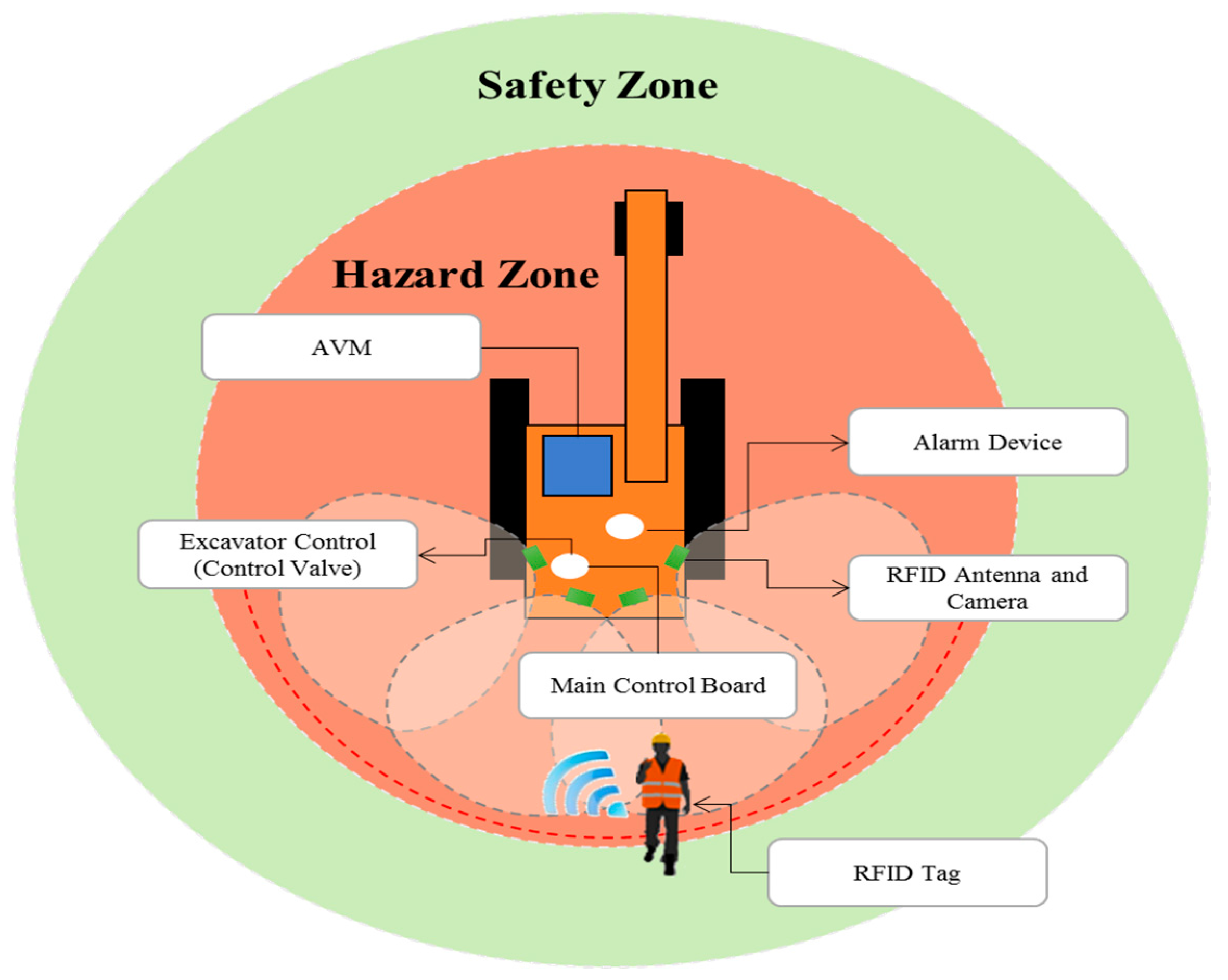
Figure 2.
Operation scenario of the proposed system.

Figure 3.
Hardware block diagram of the proposed system.

Figure 4.
Basic principles of the Around View Monitor (AVM) system.
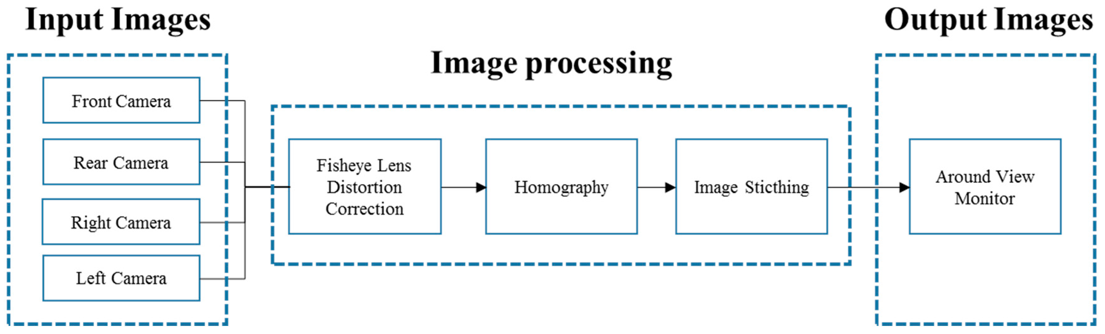
Figure 5.
AVM screen modes.
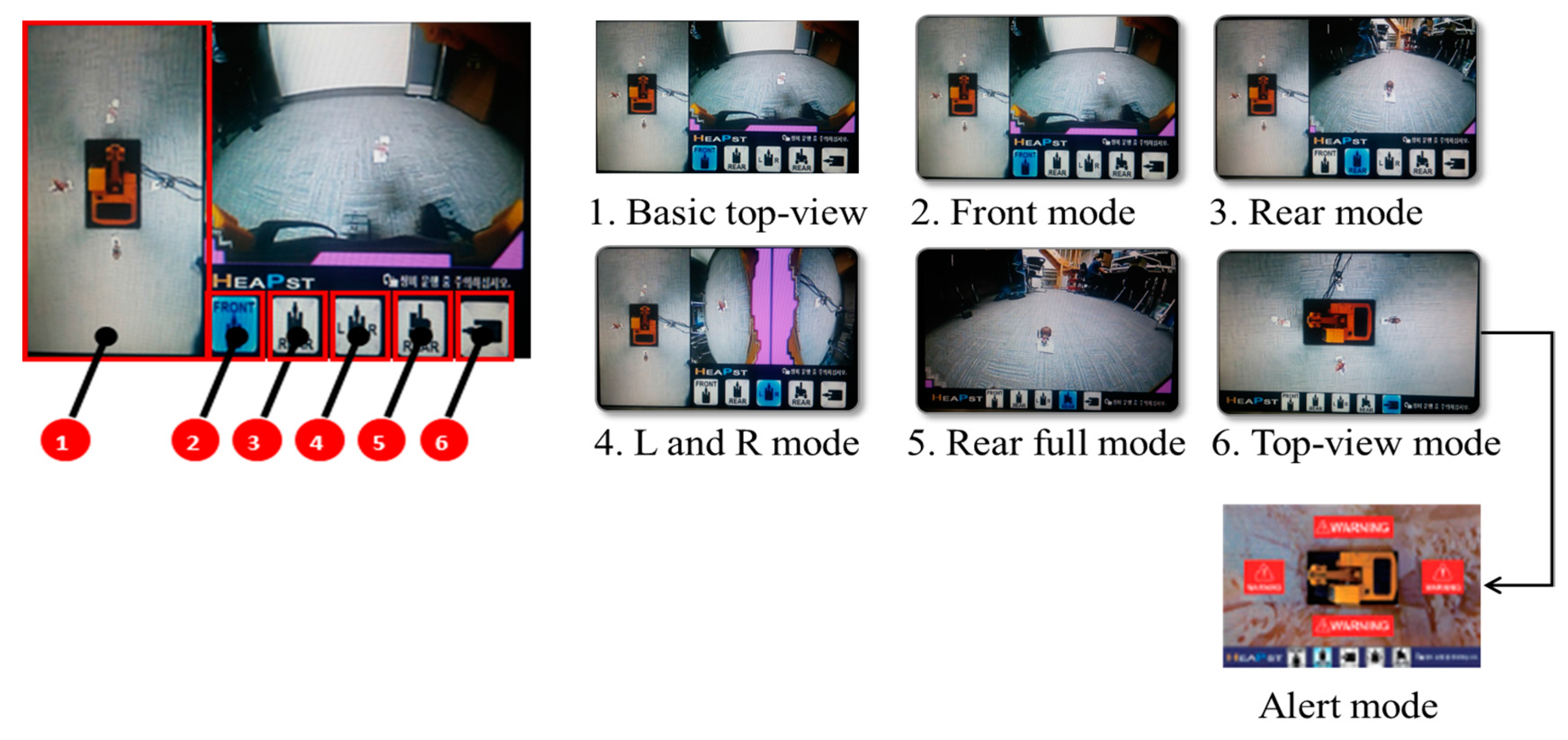
Figure 6.
Display device (AVM) and fisheye cameras.
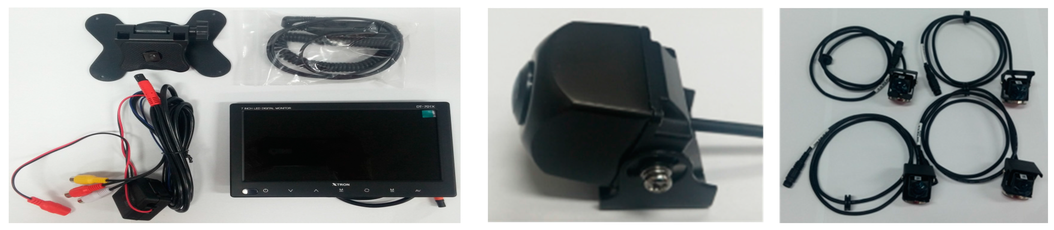
Figure 7.
Remote control.
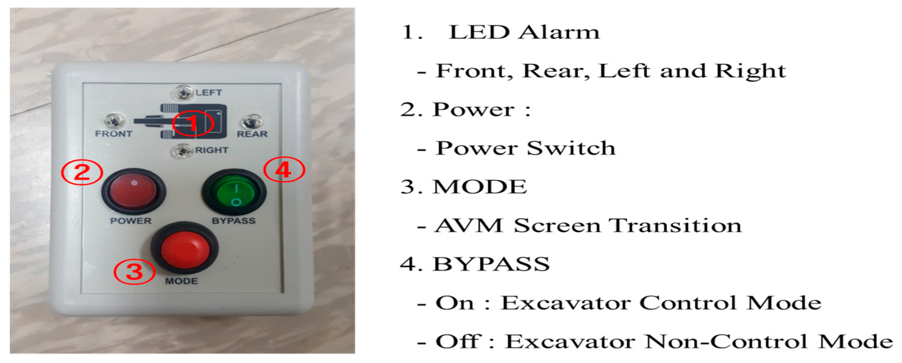
Figure 8.
Radio frequency identification (RFID) antenna.
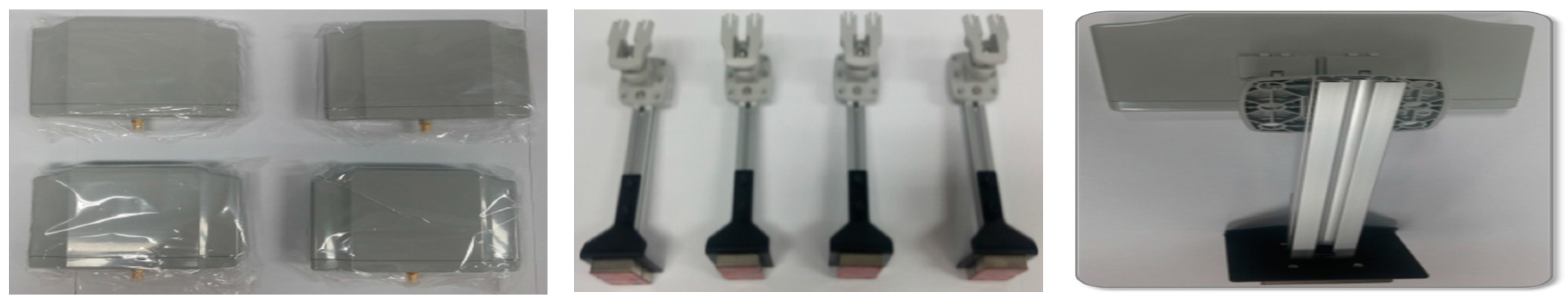
Figure 9.
Major components of excavator.

Figure 10.
Main control board.
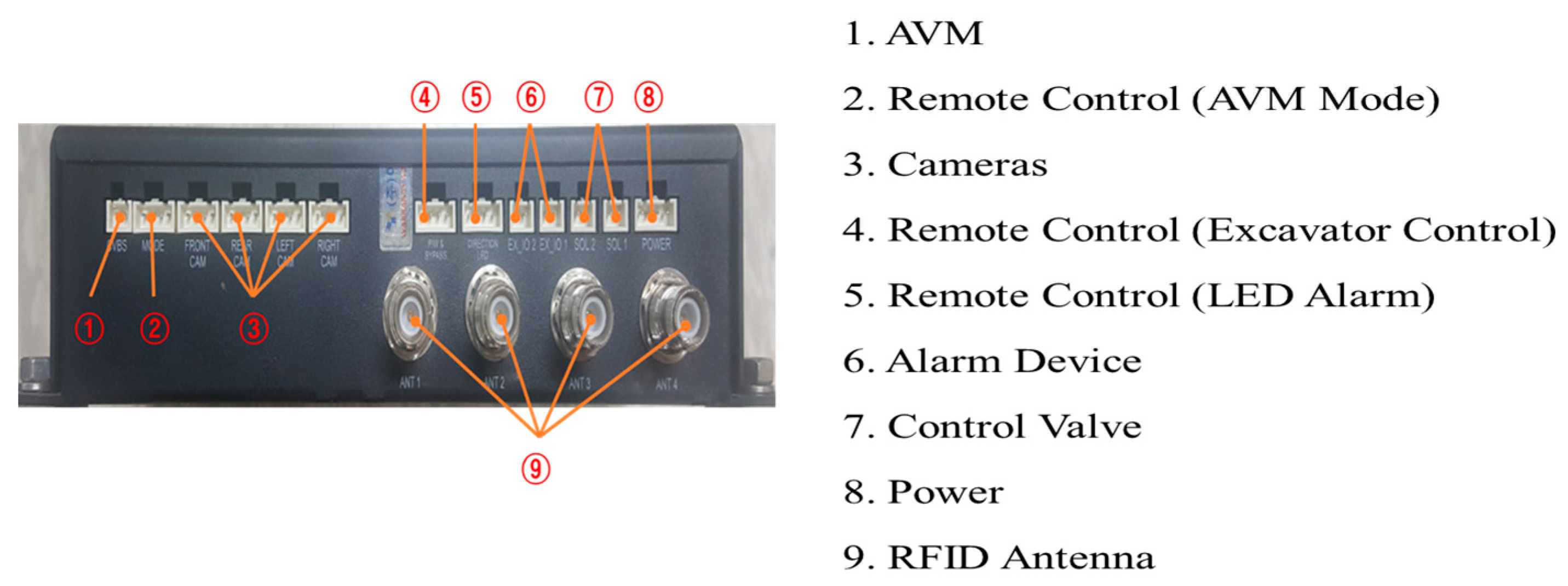
Figure 11.
Overview of the system.

Figure 12.
Result of the temperature cycle test.


Figure 13.
Result of the reliability test of AVM system.

Figure 14.
RFID detection area Test-1.

Figure 15.
Result of RFID detection area Test-1.

Figure 16.
RFID detection area Test-2 and 3.

Figure 17.
Result of RFID detection area Test-2 and 3.

Figure 18.
False alarm test.
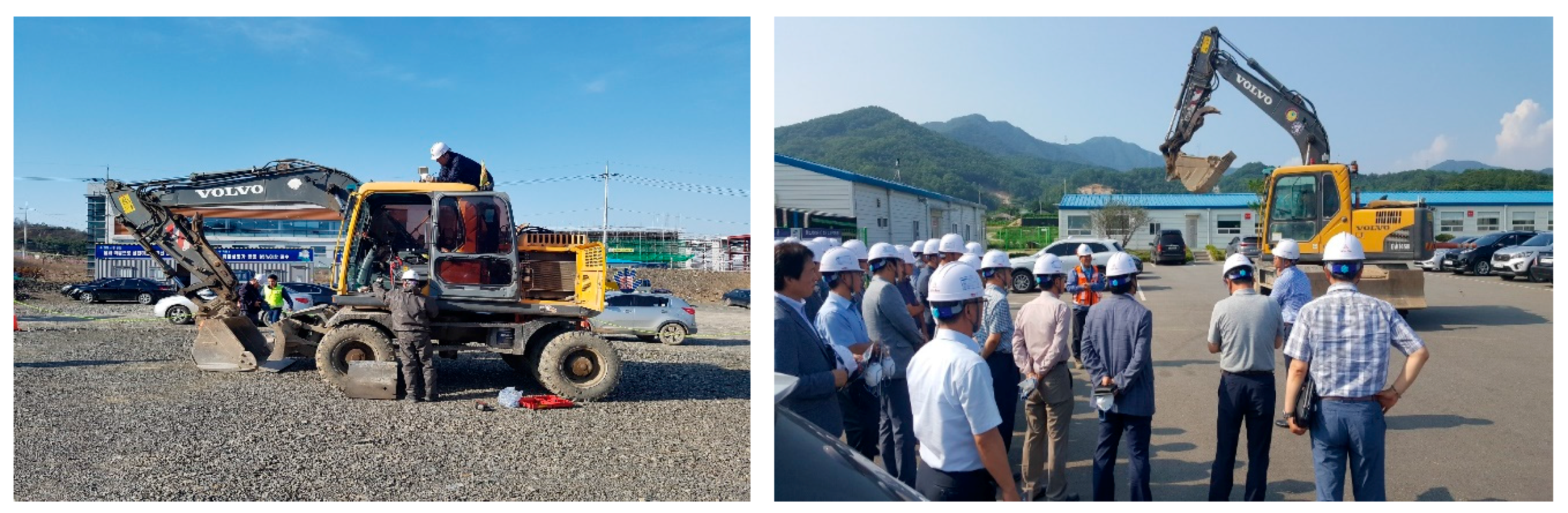
Figure 19.
Scheme for the installation of devices.
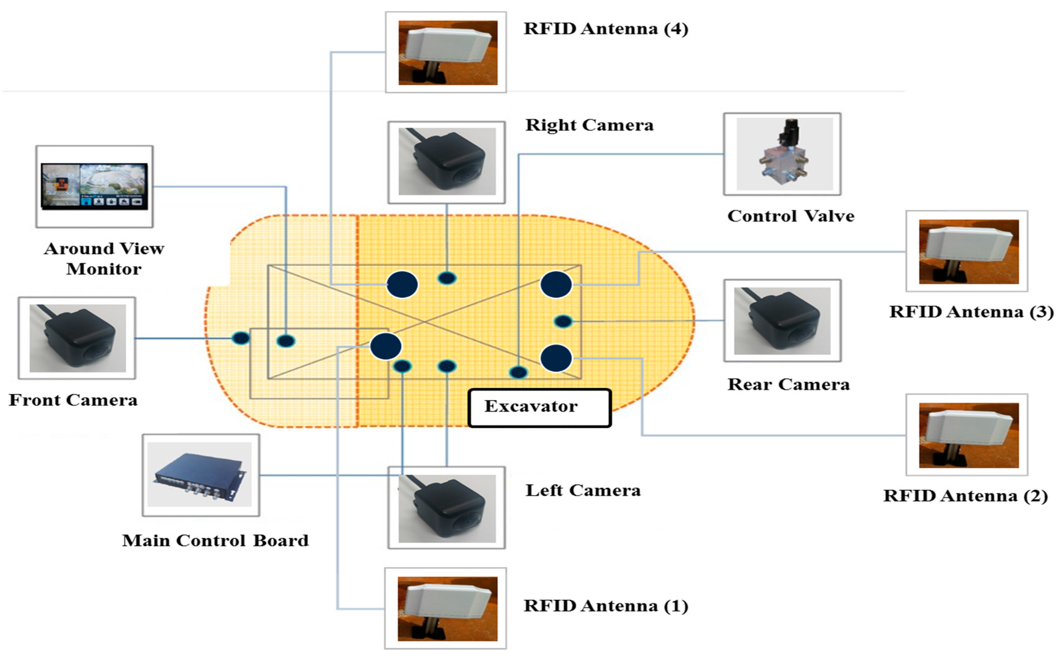
Figure 20.
The field test (travel control).


| Feature | GPS | Laser | Magnetic Fields | Radar | Ultrasound | Radio Frequency | Video | RFID |
|---|---|---|---|---|---|---|---|---|
| Detection Range | Long | Medium | Short | Short/Medium | Short | Short/Medium | Medium | Short/Medium |
| Accuracy of Data | GPS very much dependent on the environment | High | Low/Medium | Medium | Low/Medium | Low/Medium | Medium | Medium |
| Update Rate | High | High | High | High | High | High | High | High |
| Installation | Low/Medium | Medium | Medium | Low/Medium | Low/Medium | Low/Medium | Low/Medium | Low/Medium |
| Cost | Low/Medium | High | Medium/High | Low/Medium | Low | Low/Medium | Low | Low/Medium |
Table 2.
Comparison of proximity warnings technology.
| Reference | Summary | Detection Technology | Main Function | |||
|---|---|---|---|---|---|---|
| Vision | Alert | Equipment Control | Location | |||
| [18] | Proximity warning system in order to prevent collision accidents in open-pit mines based on GPS, wireless networks, and 3D mapping technologies | GPS (Wireless networks and 3D mapping) | 3D map | Audible and Visual | - | 3D coordinate (PC server) |
| [12] | Proximity detection and alert technology for safe construction equipment operation | Magnetic Field | - | Audible and Visual | - | - |
| [17] | A proximity warning system for surface and underground mining | Magnetic Field | - | Vibrating | - | - |
| [5] | Real-time construction worker and equipment operator proximity safety alert system based on RF technology | Radio Frequency (RF) | - | Audible and Visual | - | - |
| [35] | A radar and camera-based proximity warning system for dump trucks | Radar and Camera | Camera (Front and Rear) | Audible and Visual | - | - |
| [25] | RFID-based monitoring system for prevention of accidents involving heavy equipment, such as excavators, cranes, and trucks | RFID (Wireless networks) | - | Warning Signal | - | Working Area Estimation (PC server) |
| Proposed Technology | Proximity warning and excavator control system for prevention of collision accidents | RFID | Camera (360° around view) | Audible and Visual | Excavator control | |
Table 3.
RFID specifications.
| Classification | Factors | |
|---|---|---|
| RFID reader | RF power Frequency Antenna | Max 1 W 917.3–920.3 MHz 4 ports (transmitting and receiving) |
| RFID antenna | Size Weight | 295 g 130 by 100 by 20 (mm) |
| Polarization | Hor. (dBiL)/2.7 Ver. (dBiL)/−0.15 RHCP (dBic)/4.4 | |
| RFID tag | Type Size | ISO-18000-6C 100 by 30 (mm) |
| Alarm device | Alert type | LED and audible |
Table 4.
Comparison between the proposed system and a conventional system.
| Conventionally Excavator System | Excavator Control System |
|---|---|
 |  |
Table 5.
Operation principles of proposed system.
| Normal | Hazard |
|---|---|
 |  |
Table 6.
Control valve.
| Swing Control Valve | Travel Control Valve |
|---|---|
 |  |
Table 7.
Results of RFID detection area Test-1, 2, and 3.
| Approach Angle (°) | Maximum Range Test | Static Test | Dynamic Test | |||
|---|---|---|---|---|---|---|
| Max. (m) | Mean (m) | Max. | Mean (m) | Max. | Mean (m) | |
| 0 | - | - | - | - | - | - |
| 10 | 4.4 | 4.0 | - | - | - | - |
| 20 | 4.9 | 4.3 | - | - | - | - |
| 30 | 5.3 | 5.0 | 4.3 | 3.9 | 3.7 | 2.8 |
| 40 | 7.0 | 6.8 | 4.6 | 4.1 | 4.0 | 3.5 |
| 50 | 8.1 | 7.7 | 5.2 | 4.8 | 4.7 | 4.1 |
| 60 | 8.5 | 8.2 | 5.2 | 4.7 | 4.9 | 4.1 |
| 70 | 8.9 | 8.7 | 6.4 | 5.9 | 5.0 | 4.3 |
| 80 | 9.2 | 8.9 | 6.5 | 5.9 | 5.2 | 4.7 |
| 90 | 9.1 | 8.9 | 6.3 | 5.7 | 4.9 | 4.2 |
| 100 | 9.2 | 8.9 | 6.4 | 5.9 | 5.1 | 4.5 |
| 110 | 8.9 | 8.6 | 6.4 | 5.8 | 4.9 | 4.1 |
| 120 | 8.7 | 8.5 | 6.5 | 5.8 | 5.1 | 4.4 |
| 130 | 8.6 | 8.3 | 6.3 | 5.6 | 5.0 | 4.4 |
| 140 | 8.1 | 7.9 | 5.3 | 4.8 | 4.5 | 3.7 |
| 150 | 7.3 | 7.0 | 4.4 | 4.0 | 3.6 | 2.9 |
| 160 | 4.7 | 4.2 | - | - | - | - |
| 170 | 4.0 | 3.6 | - | - | - | - |
| 180 | - | - | - | - | - | - |
Table 8.
Results of false alarm test.
| Distance | Static Test | Dynamic Test | Swing Test | |||
|---|---|---|---|---|---|---|
| False Positives | False Negatives | False Positives | False Negatives | False Positives | False Negatives | |
| 3 m | 0 | 0 | 0 | 0 | 0 | 0 |
| 4 m | 0 | 0 | 0 | 2 | 0 | 7 |
© 2017 by the authors. Licensee MDPI, Basel, Switzerland. This article is an open access article distributed under the terms and conditions of the Creative Commons Attribution (CC BY) license (http://creativecommons.org/licenses/by/4.0/).
Share and Cite
MDPI and ACS Style
Jo, B.-W.; Lee, Y.-S.; Kim, J.-H.; Kim, D.-K.; Choi, P.-H. Proximity Warning and Excavator Control System for Prevention of Collision Accidents. Sustainability 2017, 9, 1488. https://doi.org/10.3390/su9081488
AMA Style
Jo B-W, Lee Y-S, Kim J-H, Kim D-K, Choi P-H. Proximity Warning and Excavator Control System for Prevention of Collision Accidents. Sustainability. 2017; 9(8):1488. https://doi.org/10.3390/su9081488
Chicago/Turabian StyleJo, Byung-Wan, Yun-Sung Lee, Jung-Hoon Kim, Do-Keun Kim, and Pyung-Ho Choi. 2017. "Proximity Warning and Excavator Control System for Prevention of Collision Accidents" Sustainability 9, no. 8: 1488. https://doi.org/10.3390/su9081488
Note that from the first issue of 2016, this journal uses article numbers instead of page numbers. See further details here.