Study on Dynamic Response of Novel Masonry Structures Impacted by Debris Flow


1
State Key Laboratory of Disaster Reduction in Civil Engineering, Tongji University, Shanghai 200092, China
2
Research Institute of Structural Engineering and Disaster Reduction, Tongji University, Shanghai 200092, China
*
Author to whom correspondence should be addressed.
Sustainability 2017, 9(7), 1122; https://doi.org/10.3390/su9071122
Submission received: 7 May 2017
/
Revised: 20 June 2017
/
Accepted: 23 June 2017
/
Published: 27 June 2017
(This article belongs to the Special Issue Building Simulation and Resilience of Buildings to Extreme Weather Events)
Abstract
:Debris flow is a very destructive natural disaster. This paper presents a novel masonry structure with strong resistance to debris flow—by using walls that are set with braces and filled with straw bricks. This structure was designed according to the concepts of sustainability. In order to study the dynamic response of this novel masonry structure under debris flow, finite element models of different masonry structures were established by means of LS-DYNA software. The responses of this novel structure and other traditional structures were calculated and compared when the rock of debris flow hits the center of the wall. Results showed that the out-of-plane stiffness of the impacted wall with cross braces was enhanced in this novel structure, leading to an increased resistance to the impact of debris flow more effectively. Furthermore, braces were able to stop rocks in the debris flow and dissipate the corresponding energy through deformation. These braces also improved anti-collapse capabilities, leading to an increase in the safety of people’s lives and properties. This novel structure is a response to national policies and plans, which plays an active role in promoting sustainable development of society.
1. Introduction
Debris flow—mixed with a large number of solid substances—is a complex multiphase fluid that can withstand a huge impact. It is a global geological hazard that often occurs in mountainous areas [1] with a low vegetation coverage. Debris flow is made by both natural and human factors, which make its outbreak sudden and unpredictable. In the context of global warming, extreme weather occurs frequently and heavy rainstorms often trigger debris flow [2]. In situations where debris flow occurs, highways, railways, bridges, and other transportation facilities as well as communication infrastructures and buildings are destroyed or buried. This results in a very large number of casualties and property losses [3]. Accordingly, research of resilience to debris flow disasters have been studied for decades. This paper presents a novel masonry structure to improve the resilience of the structure in a debris flow region.
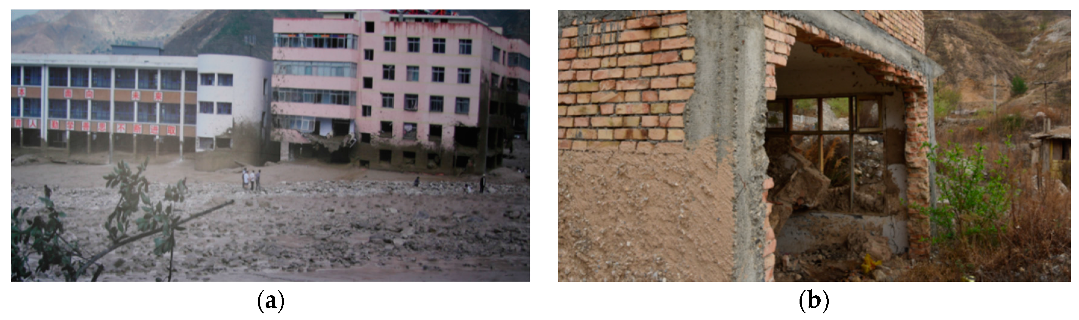
China is a mountainous country, with mountain areas accounting for about two-thirds of the land area. Debris flow erupts frequently and with high intensity in the western regions of China [4], especially after the Wenchuan earthquake, which provided a large number of unconsolidated deposits [5]. On 7 August 2010, a large-scale debris flow occurred in Zhouqu County. In this disaster, 12,877 people were killed and 457 people were missing; more than 5500 houses were destroyed and more than 230 acres of arable land were buried. Boulders in the debris flow were the main cause of the destruction. More than 40 boulders—over 30 t—were found in the alluvial fan [6]. On 10 July 2013, a number of debris flow disasters occurred in Wenchuan County. Among them, debris flow in Wentou Gully lasted for about three hours, resulting in serious damage of 39 houses in Qiangfeng Village. Boulders, of which the largest was 4.4 m × 3.5 m × 2 m, were found everywhere in the alluvial fan [7]. Damages caused by the debris flow are shown in Figure 1. Debris flow disasters have also brought great losses in other parts of the world. On the morning of 1 April 2017, a debris flow triggered by heavy rain occurred in Mocoa, Colombia. The city was seriously damaged with the streets full of mud and boulders. Water supply, power, and gas systems were destroyed. As of 6 April 2017, 301 people were killed in the disaster, including 92 children.
In order to clarify the mechanism of debris flow, incessant studies were underway all over the world since the 20th century. Dynamic characteristics of debris flow movements have become very important subjects among these studies. These characteristics contain the current velocity, flow quantity, bulk density, and impact force.
The current debris flow velocity is one of the core contents in the study of the dynamic characteristics of debris flow, and it is also one of the most important parameters in engineering design of controlling debris flow. Therefore, it has attracted the attention of scholars all over the world. At present, methods of determining the velocity include field observation, experimental test, and theoretical estimation. In 1999, Uddin [8,9] carried out field observations on the surface velocity of debris flow in Yakedake mountainous area in Japan and calculated the current velocity based on the measured data. Based on the experimental results, Takahashi [10,11] found that the vertical velocity was proportional to 1.5 times the power of the total flow depth of debris flow. However, because debris flow is a complex multi-phase non-Newtonian fluid, it is not easy to measure its velocity by means of field observations and experimental measurements. As a result, empirical or semi-empirical formulas are widely used. Some examples are shown in Table 1: the Dongchuan viscous debris flow formula [12], the Wudu viscous debris flow formula [13], the Zhamalong watery debris flow formula [14], and the Beijing watery debris flow formula [15]. Almost all of these formulas are based on the Chezy-Manning formula, though the parameters of the formulas are determined according to the different observation data. In addition, some scholars focus on the prediction of the debris flow’s average velocity. Cao [16] found an approach using radial basis function (RBF) neural network and gravitational search algorithm (GSA) for predicting debris flow velocity.
Where is the velocity of debris flow; is the Manning roughness coefficient of debris flow, whose value is related to the depth of the flow; is the average depth of debris flow; is the longitudinal slopes of debris flow; k is the average velocity coefficient of the flow section, generally k = 0.7; is the roughness coefficient of debris flow; is the resistance correction coefficient of debris flow, whose value is related to the density of the flow; R is the hydraulic radius.
For the flow quantity, it not only reflects the strength, size, and fluid properties of debris flow, but also has a significant guidance on the design of anti-debris-flow constructions. Some scholars have studied the flow quantity since the 1930s. Sirbin put forward a relevant formula in 1960. Fleishman presented a comprehensive coefficient in 1973, which considers the characteristics of debris flow, the solid matter in debris flow, and the additional flow caused by blockage, where the values were between 2 and 8 [17].
The bulk density is also an important parameter which plays a vital role in studying the impact of debris flow. At present, the determination of the bulk density is divided into two types: on-site investigation test method and survey method [18].
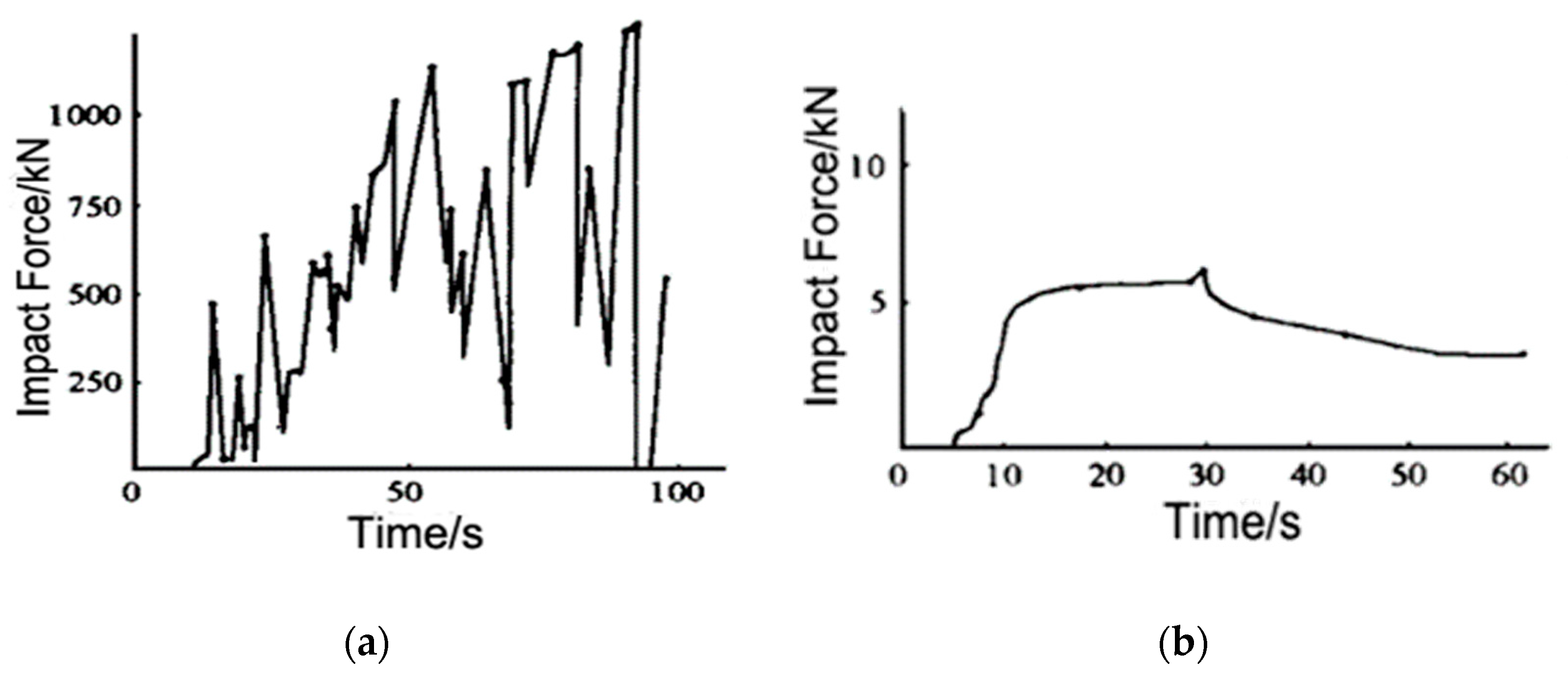
For the study of the impact force of debris flow, because of the randomness and the disorder of the heavy particle content, as well as its size and distribution, it is difficult to study the impact force of debris flow. The impact force of debris flow mainly includes the hydrodynamic pressure and the impact force of large stones. Most of the scholars analyze the impact through the on-site measured data and the experimental simulation analysis [19]. Valentino [20] simulated and tested the particle flow tank, and obtained the spectral characteristics of the particle flow impact. Miyoshi [21] obtained the constituent parts of the impact force through the simulation test of dams under debris flow. Chen [22] made a series of debris flow impact tests on the gully debris flow, and found that the impact force of debris flow grows nonlinearly when the solid particle size increases. Using the advanced force sensor and the data acquisition system, Hu [23] collected the data of the debris flow in Jiangjia Gully, and obtained a great deal of valuable information. According to the observation data of Jiangjia Gully, Wu [12] proposed the expression of dynamical pressure of debris flow. Chen [24] used Newton’s second law to establish the formula for calculating the impact force of a two-phase debris flow. According to the research of Wu [12] on the debris flow of Jiangjia Gully, the impact load of debris flow could be generalized into a sawtooth pulse, a rectangular pulse, and a spike pulse, as shown in Figure 2, respectively.
Masonry structure is one of the main structural forms in mountainous areas. Some scholars have studied the masonry structures impacted by debris flow. Zhang [25,26] made a destructive experiment on a masonry wall, and measured the failure patterns and processes of the wall under the impact, which were then compared with the theoretical simulation results. The test results showed that under the action of uniform debris flow, the failure mode of the masonry wall is an out-of-plan flexural failure, which is similar to that under static loads. Cheng [27] studied the fluid–solid interaction dynamic response of masonry structures under debris flow through the use of simulation. The results showed that the parameters of debris flow (velocity and width) and masonry structure (height and length/width ratio) had an important influence on the stress that was generated in the masonry structure.
This study aims to meet the demands of national plan for disaster prevention and reduction, which is committed to sustainable development of China [28]. In this paper, a novel masonry structure is proposed to increase the traditional masonry structure’s resistance to debris flow. After a conceptual design, the numerical simulation method is well established using LS-DYNA software and some simulation considerations are introduced. Then the simulation results of the novel masonry structure and traditional masonry structure are compared and presented to show the dynamic responses under the debris flow, and the hidden mechanism is also discussed. Besides, sustainability of this novel structure is analyzed. Finally, some proposals on the engineering applications of debris flow are put forward to increase the safety and sustainability of the masonry structures in mountainous areas.
2. Conceptual Design of a Novel Masonry Structure
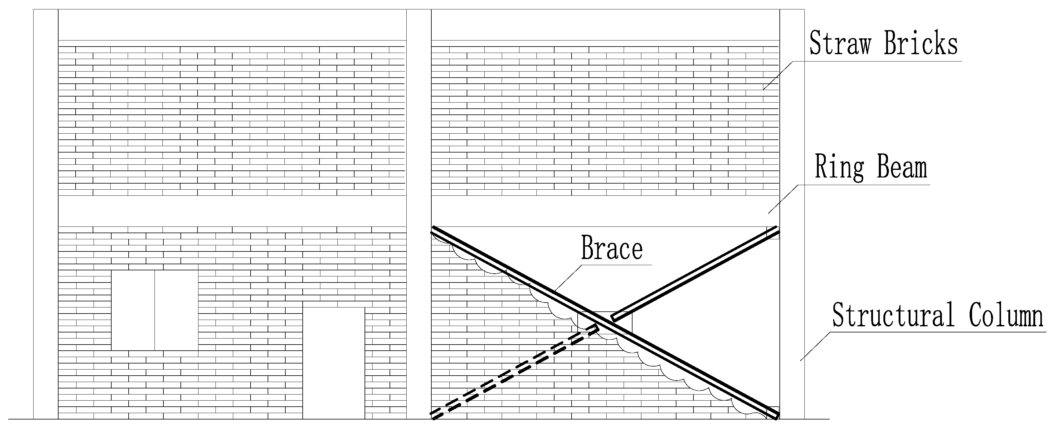
Considering that economic conditions of the mountainous areas are relatively poor [29], and the anti-debris-flow impact capacity of the existing masonry structures are generally low [30], proposing some measures to increase the resistance of masonry structures are of great importance. Consequently, a novel masonry structure with strong resistance to geological disasters, whose walls are set with steel braces to improve the out-of-plan and lateral stiffness of the walls, is proposed. Tensile-resistance and bending-resistance of the impacted braces are fully used to impede rocks and increase the integrity of the structure, and the braces could also support the walls and prevent a collapse after the penetration of rocks.
In addition, for the newly built masonry structure, traditional bricks can be replaced by straw bricks, which are considered as renewable material [31]. While providing the same mechanical properties (compression and shear strength) as traditional bricks, straw bricks are much lighter [31]. That is, even if the brick wall collapsed under the impact of debris flow (or other natural disasters, like an earthquake), such light bricks will not injure residents or cause large damages. The conceptual design of such a novel masonry structure is shown in Figure 3.
2.1. Novelty of the Design
There are mainly two novelties to this research: (1) Masonry walls are set with steel braces which help improve the out-of-plan and lateral stiffness. Hence, the masonry structure becomes resistant to geological disasters; (2) Traditional bricks are replaced by straw bricks, which is considered as renewable material [31].
There are several ways to improve the stiffness of masonry structures to resist disasters. Wight [32] used a pre-stressing technique to improve the ductility and stiffness of a masonry structure, and compared its seismic behavior with that of an ordinary masonry structure. The results showed that the strengthened structure performed much better than the ordinary one. However, this technique has its own limits. Pre-stressing technique needs skillful workers and high construction quality, which are hard to promote in rural places. Luciano [33] and Kiss [34] reinforced masonry structure with fiber reinforced plastic (FRP), and their studies showed that responses of the structure is significantly influenced by FRP. Gattesco [35] strengthened stone masonry walls with glass fiber reinforced polymers (GFRP) through the use of reinforced mortar coating and steel-cord reinforced repointing. By comparing the shear behavior if reinforced walls with unreinforced walls, the structural effectiveness of the reinforcing technique is highlighted. Although the construction of FRP or GFRP reinforced structure is simple, the cost of these two materials are not a light burden for the residents in mountainous areas.
Steel braces were less likely to be used in a typical masonry structure. They are widely used in frame structures and masonry buildings with the frame structure being used at lower floor for resisting earthquakes [36]. Khan’s [37] study showed that buildings with eccentric bracings have lower drift demand and probability of collapsing. The results obtained by Varum [38] showed that a retrofitting bracing system that was adopted for the structure was tested to be appropriate and that its location in the structure may highly influence the overall structural seismic response. According to these studies, this technique is quite simple and practical. However, all these studies were based on the aim for resisting earthquakes [36]. The interaction between debris flow and structures has rarely been studied in detail [39], not to mention masonry structural design for debris flow resistance. In addition, Chinese government has promulgated the “National Comprehensive Disaster Prevention and Reduction Plan” to lift the level of disaster resistance capability in poor areas. Consequently, study on this novel masonry structure not only fills in the vacancies of previous studies, but also fully meet the demands of the national plan.
Besides, straw bricks, which are considered as renewable material [31], were used in this novel structure. Straw is a sufficient resource in rural places [40]. The use of straw bricks can fully reduce the cost of construction in poor areas, which is also in line with the basic national strategy.
To sum up, masonry structure is one of the main structural forms in mountainous areas, where debris flow erupts frequently and immensely. However, there has never been such a design, with walls set with braces and filled with straw bricks that is used to increase the structural resistance to debris flow. Consequently, it is believed that the proposed design is novel, and that the design meets the demands of the national plan and has profound practical significance to the local people in rural, disaster-prone areas.
2.2. Sustainability of the Design
The sustainability of this design is embodied in three aspects: economy, environment, and society. The proposed steel braces strengthening technique is quite simple and practical, because this kind of technique has been widely used in frame structures, and it is mature enough to make local constructions much easier [36]. Its simplicity and cost effectiveness can help local dwellers to enhance performance of existing masonry structures without rebuilding them, which can bring a large number of economic benefits. Besides, straw bricks are used for reasons of availability and economy because of the abundance of straw in rural areas [40]. It can reduce a great amount of money by using straw bricks to the construction.
As for the environment, the current popularly used clay bricks consume massive earth resources, which become irreversible for the environment. Compared with clay bricks, straw bricks can be used again by nature after they are destroyed, because they can be decomposed by microorganisms. Straw resources are sufficient in rural areas [39]. Using it as a material for making bricks not only reduce the emissions [41] of nitrous oxide, carbon dioxide, and PM2.5 when straw burns, but also protect earth resources by declining the use of clay bricks [31]. Furthermore, the technique of this new design can help dwellers retrofit the old masonry structures without reconstruction. In this way, plenty of building resources are saved, which makes a great contribution to sustainability on the environment.
Disaster prevention and reduction play an important role in sustainability. It has a close relationship with society. Chinese government has promulgated the “National Comprehensive Disaster Prevention and Reduction Plan” to deal with these related problems [28]. The plan pays great attention to the role it plays and sets up major tasks and goals for the next five-year disaster prevention and reduction work in China. At this stage of the plan, the local governments need to promote house rebuilding in rural areas with a high risk of natural disasters and enhance the level of disaster resistance capability in those areas. According to the plan, this novel masonry structure not only fully meets the demands, but also contributes to sustainable development of China.
3. Numerical Simulation Method
3.1. Model of Debris Flow Load
Debris flow is a complex solid-liquid-gas three-phase fluid. Its impact force is composed of three parts: hydrostatic pressure, hydrodynamic pressure, and the impact of rocks [12]. Among them, hydrostatic pressure is small and can be neglected, hence only hydrodynamic pressure and the impact of rocks are considered.
3.1.1. Hydrodynamic Pressure
According to the situation that rocks impact the components and structure at the speed of the slurry when the debris flow enters the stationary stage, these hypotheses are followed:
a. The slurry, simplified as a one-dimensional Newtonian fluid, loads evenly on the impacted elements.
b. The debris flow, whose depth is as high as the first floor, is perpendicular to the wall.
According to Tang’s study [42], hydrodynamic pressure of the slurry can be calculated using the formula . The empirical coefficient K depends on the type of debris flow. As to the hydrodynamic head, for debris flow with obvious laminar characteristics and small particle size, Watanabe [43] suggested that the value of K is 2.0. For a debris flow with large solid content and large particle size, Lo [44] believed that the coefficient could reach 4. Through a number of field observations of debris flow, Zhang [45] finally concluded that the value of the coefficient of viscous debris flow should be in the range of 3.0–5.0. As for the stationary stage, according to the research of Chen [24], when the debris flow is in the stationary stage, the hydrodynamic pressure of the slurry becomes stable. Therefore, if the hydrodynamic pressure of the liquid slurry is considered, K values are 0.5. Table 2 shows the data used in this paper.
3.1.2. Rock Impact
LS-DYNA is used to simulate the large rocks in the debris flow of this paper. It is a general explicit dynamic finite element analysis program capable of simulating complex real world problems [46]. It is especially suitable for coping with fluid–solid interaction problems and nonlinear collision problems, such as high speed collision, explosion, and metal forming. At present, this program is widely considered as one of the best commercially analytical tools in engineering. Given that the interaction between debris flow and masonry structure with braces is a complex dynamic nonlinear problem, LS-DYNA can exert an enormous function on solving this problem. The impact of the debris flow on the structure is simulated by defining the initial velocity of large rocks and the contact between rocks and the structure.
Yang [47] found that boulders of debris flow mainly concentrated in the 2/5 to 3/5 of the maximum flow depth. He [48] found that, for viscous debris flow, rocks concentrated at 1/2 of the maximum depth are more unfavorable, whose typical speed is 3.5–5 m/s. Ikeya [49] found that the flow velocity is 3–10 m/s for the debris flow containing many boulders, while its velocity is in 2–20 m/s for few of the boulders. Based on the above studies and experiences, the viscous debris flow is selected for this paper. The speed of the debris flow slurry and rocks is 5 m/s, and the rock impact position is 1/2 of the stream depth, which equals the height of the first floor. Consequently, the impact condition is the most disadvantageous one, as the impact force reaches the maximum. Figure 4 shows the general view of the position at which the rock in the debris flow impacts the wall and the brace.
3.2. Model of Material
The rock mainly acts as an impact; hence, its elastic and plastic characteristics are ignored. Defined by the model MAT 20 (*MAT-RIGID), which is used to model rigid bodies [46], the rock has the elastic modulus of 5.3 × 10⁴ MPa and the Poisson ratio of 0.2. The rock is 0.5 m × 0.5 m × 0.5 m in size, and its density is defined as 2800 kg/m3, resulting in the total mass of 350 kg.
The masonry material model is defined by MAT 96 (*MAT-BRITTLE-DAMAGE). This model, which is derived from the study of Govindjee [50], is an anisotropic brittle damage model that is widely used for brittle materials. The failure strain of material unit is defined as 0.0015 by the keyword *MAT-ADD-EROSION, which provides constitutive models with failure/erosion criterions. The masonry material parameters are shown in Table 3.
In order to accurately consider some of the important characteristics of concrete under low confining pressure and tensile stress, such as strain softening, stiffness degradation, volume expansion, shear contraction, and strain rate strengthening, the model of concrete was defined by a continuous surface cap model (*MAT_CSCM_CONCRETE), which takes into account the hardening, damage, and strain rate effects of the material [46].
The material model selected for reinforcement and braces is a kinematic hardening bilinear elastic-plastic model (*MAT_PLASTIC_KINEMATIC), which is used to model the beam, shell, and solid elements [46]. The strain rate effect of reinforcement is considered by the Cowper-Symonds [51] model, and the yield stress of the steel bar can be expressed as:
where is the yield stress; is the initial yield stress; C and p are hardening parameters of the strain rate; is the strain rate; β is kinematic and isotropic hardening parameter; is the plastic hardening modulus; is effective plastic strain.
For reinforced concrete slabs, material model MAT 172 (MAT_CONCRETE_EC2), which can model a smeared combination of concrete and reinforcement, is used to simulate concrete material [52]. By defining the ratio of reinforcement in two directions, as a method of equivalent diffusion, the model can simulate the effect of reinforcing steel bars in the structure.
3.3. Model of Structure
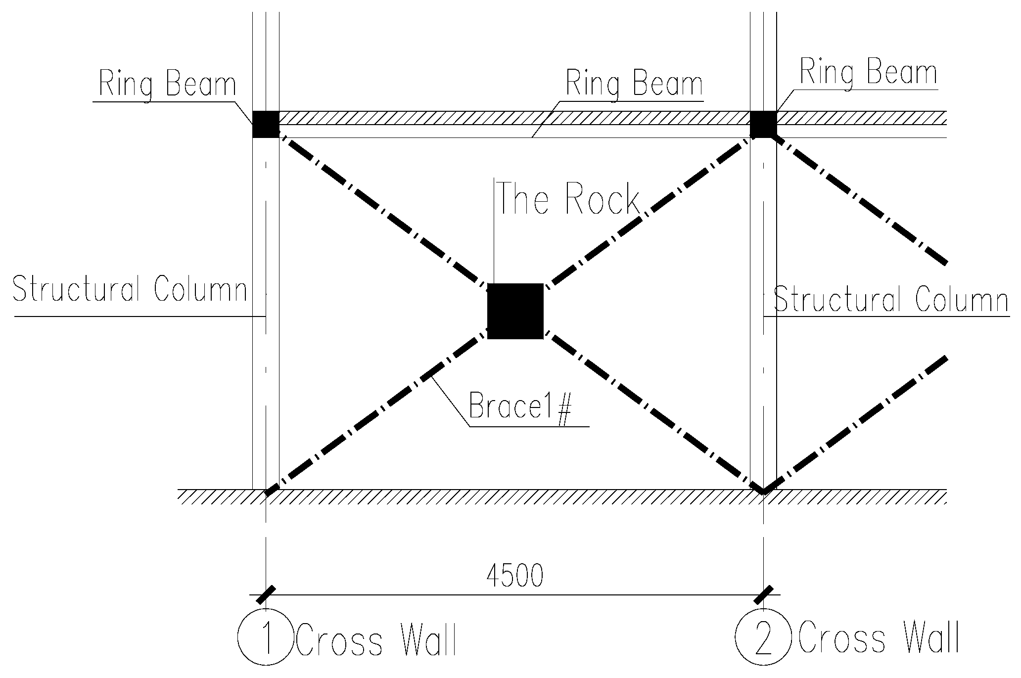
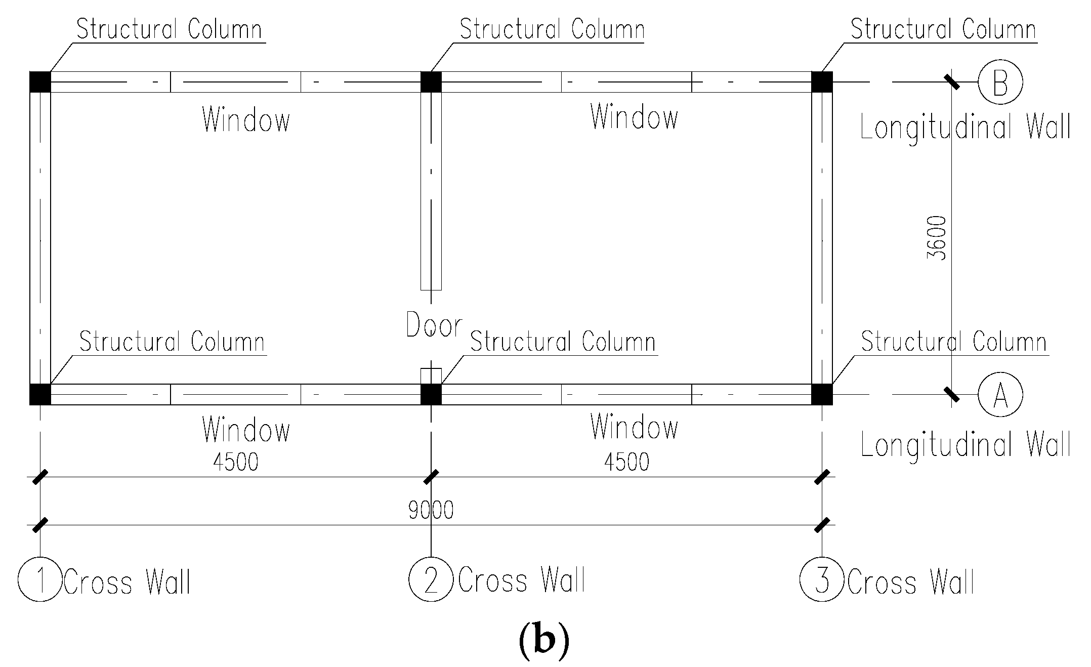
The basic masonry structure in this paper consists of two floors, with each floor height being 3.3 m. The structure is 3.6 m wide and 9.0 m long with an axis distance of 4.5 m. Layouts of the model are shown in Figure 5. Thickness of the wall is 240 mm. The section size of ring beam and structural column is 240 mm × 240 mm. The thickness of the reinforced concrete cast-in-place floor is 120 mm. The dead load of the floor is 5.0 kN/m2 (including floor weight), and the live load is 2.0 kN/m2, while the dead load of the roof is 6.0 kN/m2 (including the roof weight), and the live load is 0.5 kN/m2. In addition, the compressive strength of the straw brick is 15.0 MPa, the mortar strength is 10 MPa, the compressive strength of the concrete is 30 MPa, and HRB335 is used for longitudinal reinforcement and stirrups.
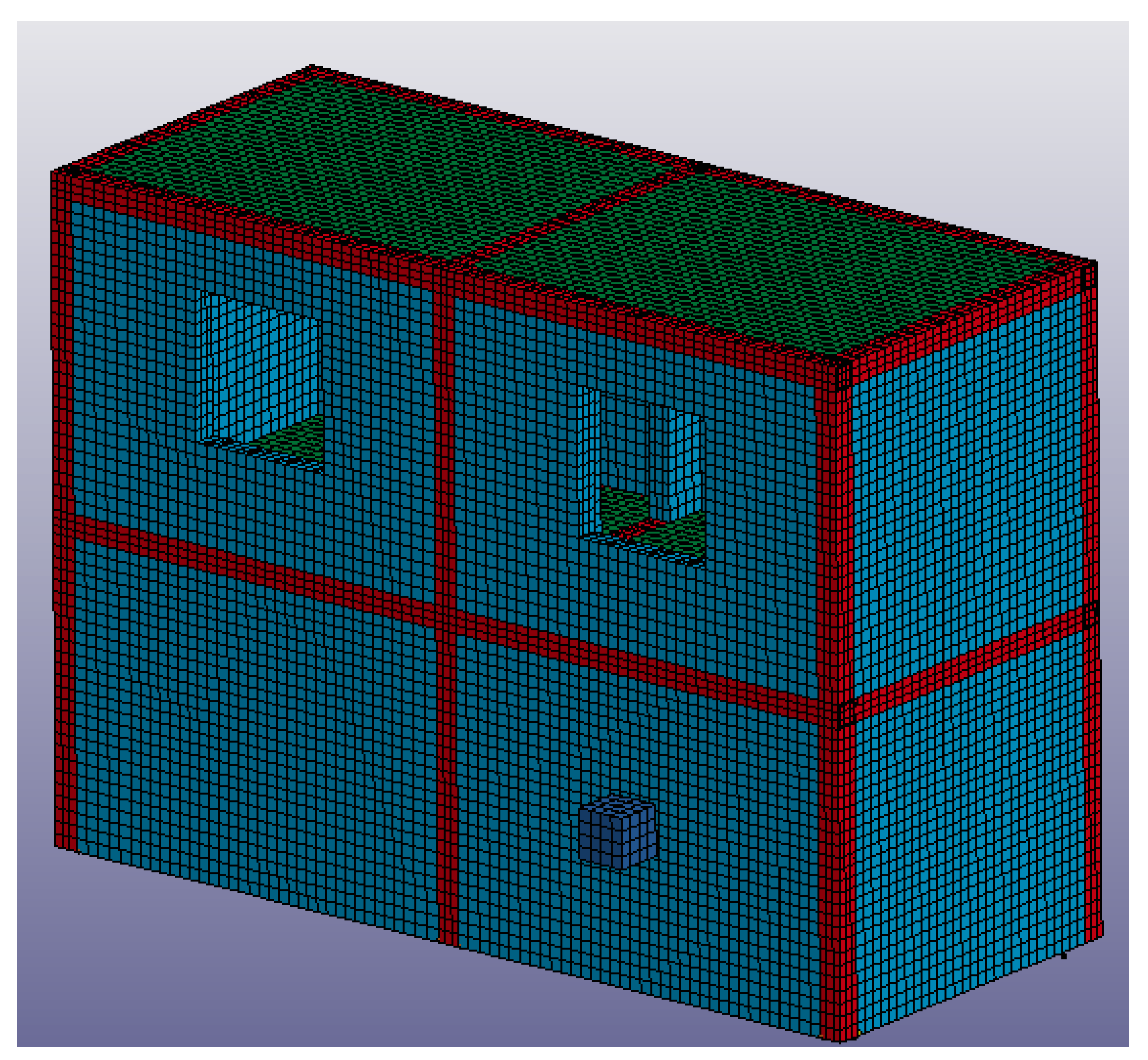
The finite element model of three different structures (model one-model three) were established (sketch map of the masonry structure is shown in Figure 6):
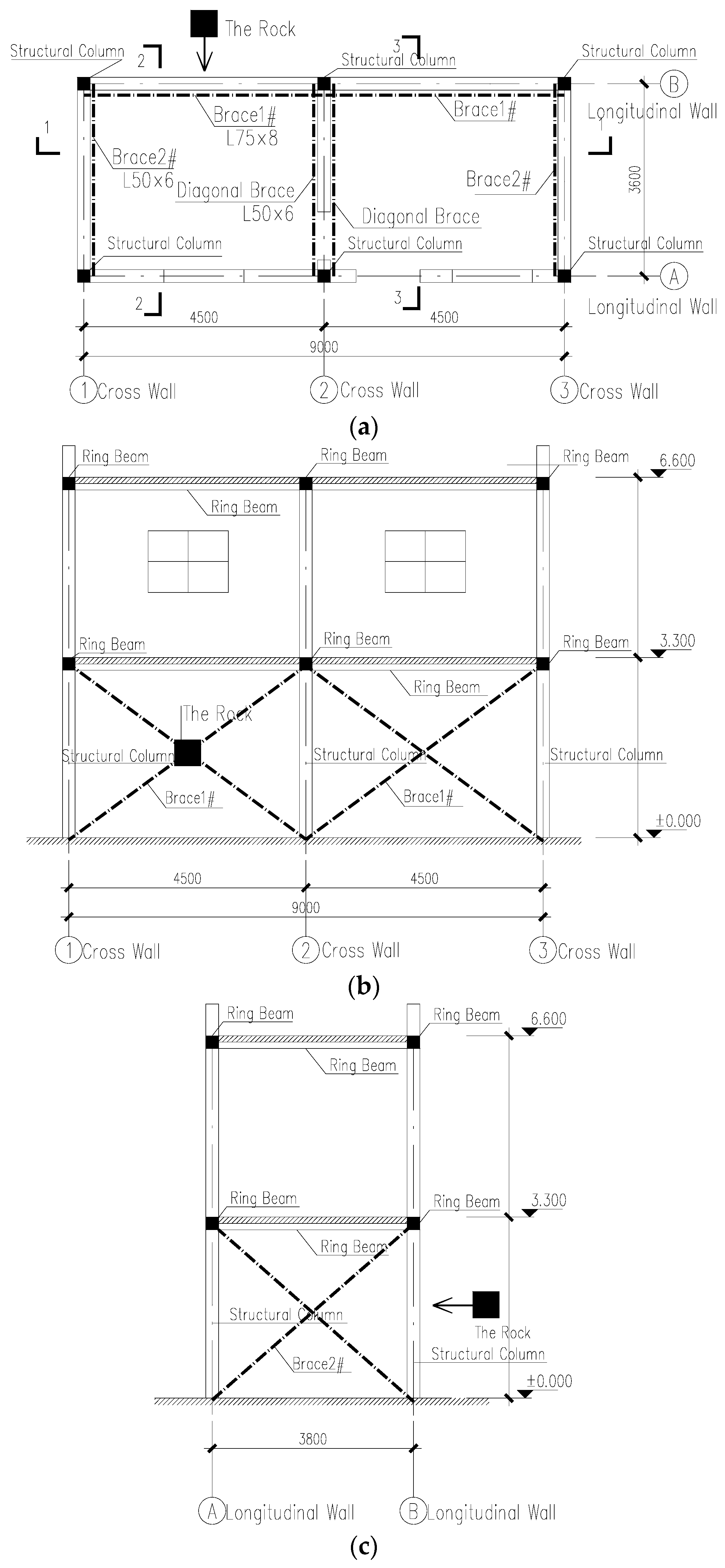
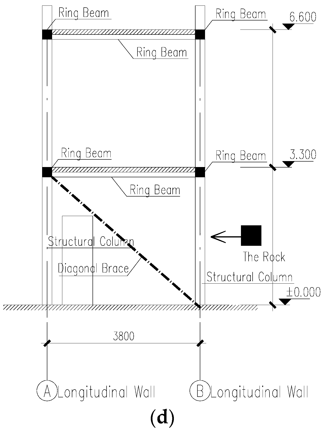
a. The layout of model one is shown in Figure 7. Cross braces are set at the walls (Axis B), which are impacted directly by the slurry and rocks of debris flow. They are also set at walls of Axis one and Axis three. However, diagonal braces are set at the wall at Axis two in order to avoid them being placed on the door. All the steels used in constructing braces are equilateral angles, and are of type Q345. The cross section of brace 1 is ∟75 mm × 8 mm, brace 2 is ∟50 mm × 6 mm, and the diagonal brace is ∟50 mm × 6 mm.
The model assumes that all the braces ends are coupled with the concrete beam-column joints, without considering the bond slip between the braces and the concrete.
b. Model two is the same as model one, except that there are no braces at the walls of axis 1–3.
c. Model three is the same as model one except that there are no braces at any of the walls. Model three resists the impact of debris flow only by the masonry structure itself.
4. Simulation Results and Sustainability Analysis
4.1. Results of Dynamic Relaxation Analysis
To identify the influence of the initial stress before the rock’s impact, the stress distribution and displacement of the masonry wall under the action of the slurry flow were calculated by the dynamic relaxation analysis, a numerical method for solving nonlinear problems. Figure 8 shows the stress distribution and displacement of the walls at axis B in model one.
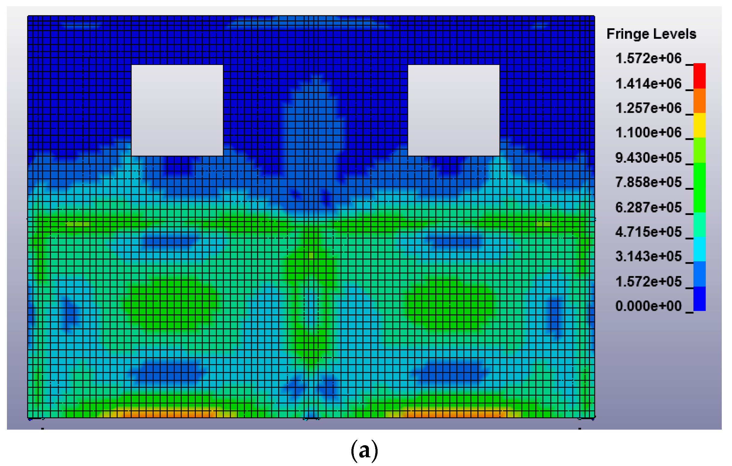
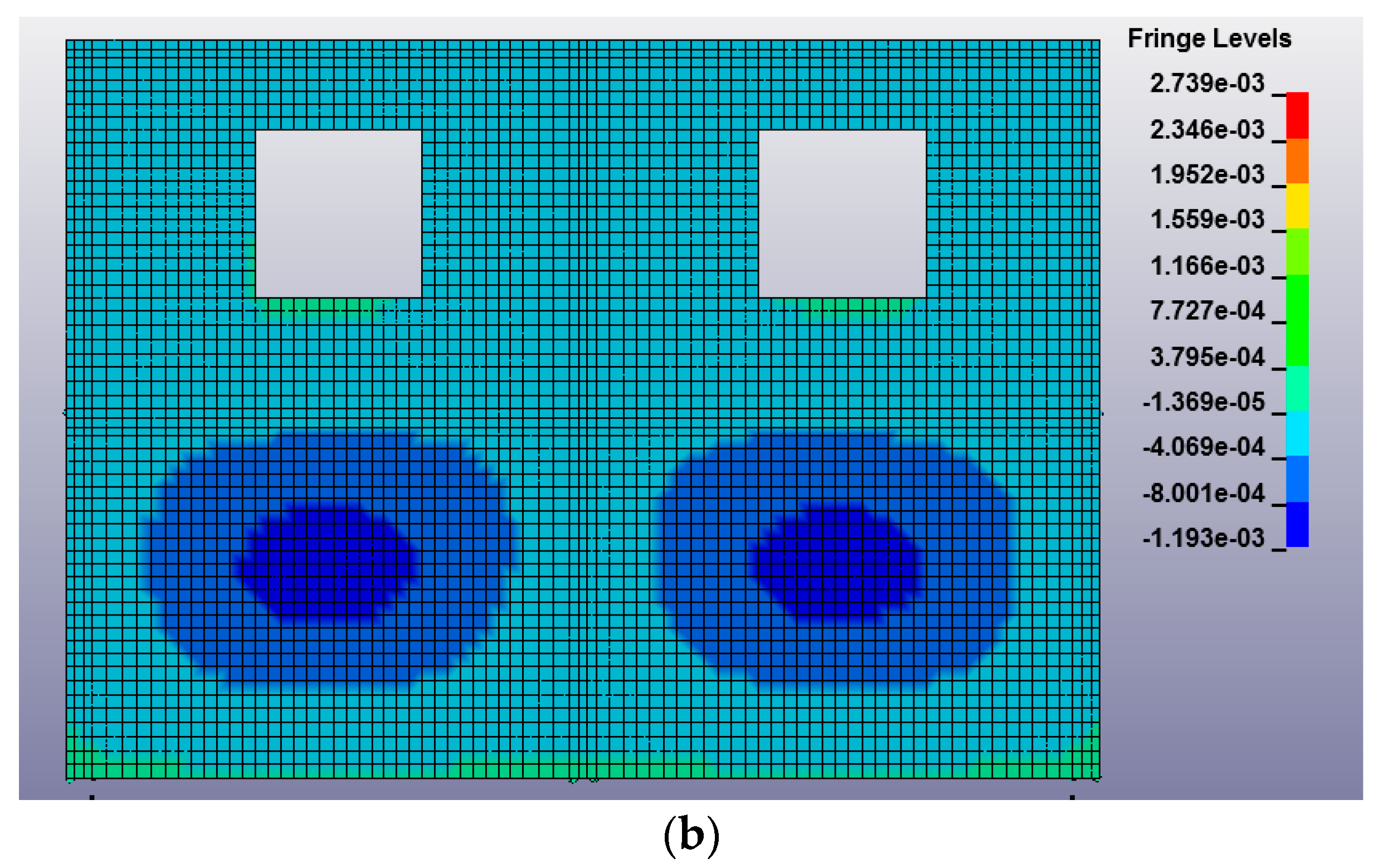
In this model, the bottom of the masonry walls was rigidly connected, hence the stress reaches maximum at the bottom under the uniform load of the debris flow slurry, which is shown as 1.33 MPa. The stress distribution of the wall decreases from the middle to the boundary, and then increases, and it is similar to that of placing a slab under the uniform load. This similarity also shows in displacement in the Y direction, which is larger in the middle and smaller around the area enclosing the middle. Besides, the stress distribution of the wall is basically symmetrical, and the stress on both sides of the middle column is slightly larger than that of the adjacent columns at both sides. According to the results, the stress of the walls is relatively small, which indicates that the impact force of the slurry is not the main factor affecting the masonry structure.
4.2. Results and Analysis in the Collision Process
4.2.1. The Impact Force of the Rock
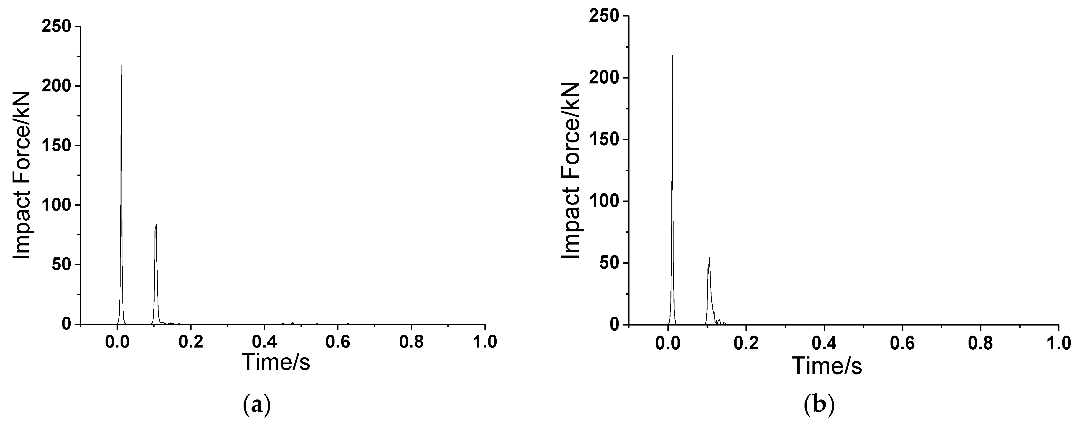
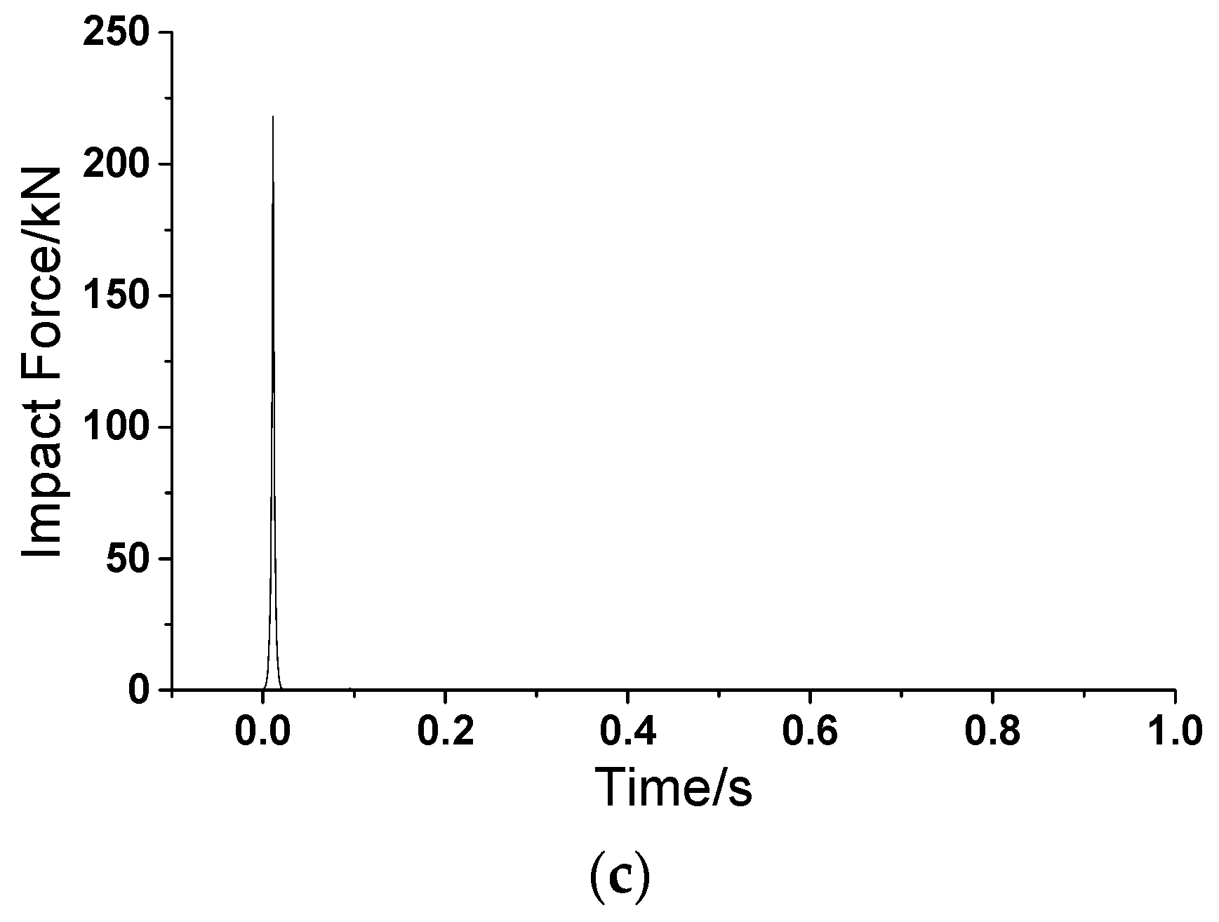
Figure 9 shows the time history curve of the impact force of model one–model three. After the action of the slurry flow, the rock began to move to the masonry wall at the speed of 5 m/s when t = 0 s. Subsequently, the collision between the rock and the wall triggered the impulsive force, which exposed the masonry element to strain failure, leading to an instant deletion. When t = 0.1 s, the rock impacted the central area of the brace. There was a large amount of kinetic energy which was dissipated by the collision between the rock and the wall, hence, the impact force on the brace was much less than that of the wall. Table 4 shows the peak value of the impact force of the rock on the masonry walls and braces.
From Table 4 and Figure 9, the peak value of the impact force on the three models is almost the same due to the contact-impact arithmetic theory. In this theory, the software checks whether the main plan and slave nodes are penetrated. If so, the impact force can be calculated by the degree of penetration, stiffness of the main plane, and speed of the rock. There are three phenomena related to such an impulsive force: (1) the collision lasts extremely short; (2) the occurrence of the force is accompanied with such a sudden collision; (3) the bricks immediately fail because of excessive strain. Besides, it can also be seen from Table 4 that the peak value of the impact force at the braces in model one is larger than that of model two. This is because braces are set at the cross walls in model one, which contributes to the stiffness of the impacted braces. Consider the energy method—the formula of the impact force is:
where F is the impact force; m is the mass; v is the velocity; k is the stiffness. Consequently, it can be seen from Equation (2) that a larger stiffness of the impacted braces leads to a larger impact force.
Another interesting observation is that there are two impulsive forces in model one and model two, while there is only one impulsive force in model three, which is the model for the traditional masonry structure case (shown in Figure 9). This does not mean that the ordinary masonry structure is allowed to have a small (less) impulse under the rock’s impact. As a matter of fact, in this case, the rock has penetrated through the wall and crashed into the house. On the other hand, for model one and model two, due to the impedance effect of the braces, the rock, first impacts the wall, and then impacts the braces, leading to two successive impulses. The latter one is smaller than the former impulsive force. Under these two cases, the rock will not thrust forward into the house, which can ensure the safety of the residents.
Due to excessive strain, nonlinear problem, and other complex conditions in the collision process, as well as the calculation accuracy related to meshing, the calculation results need to be verified by an on-site investigation results. According to Hu’s research [23], the peak value of the impact pressure under a real debris flow is 300–800 kPa, which was measured in a debris flow in Jiangjia Gully by using sensors. Calculated by the peak force of 218 kN and an impacted area of 0.25 m2, the impact pressure in model one is about 872 kPa. This value is similar to the one that was measured on-site, indicating that the proposed method can reasonably simulate the impact of a rock in debris flow. Such accuracy is acceptable in engineering applications.
4.2.2. Nodes Displacement of the Wall
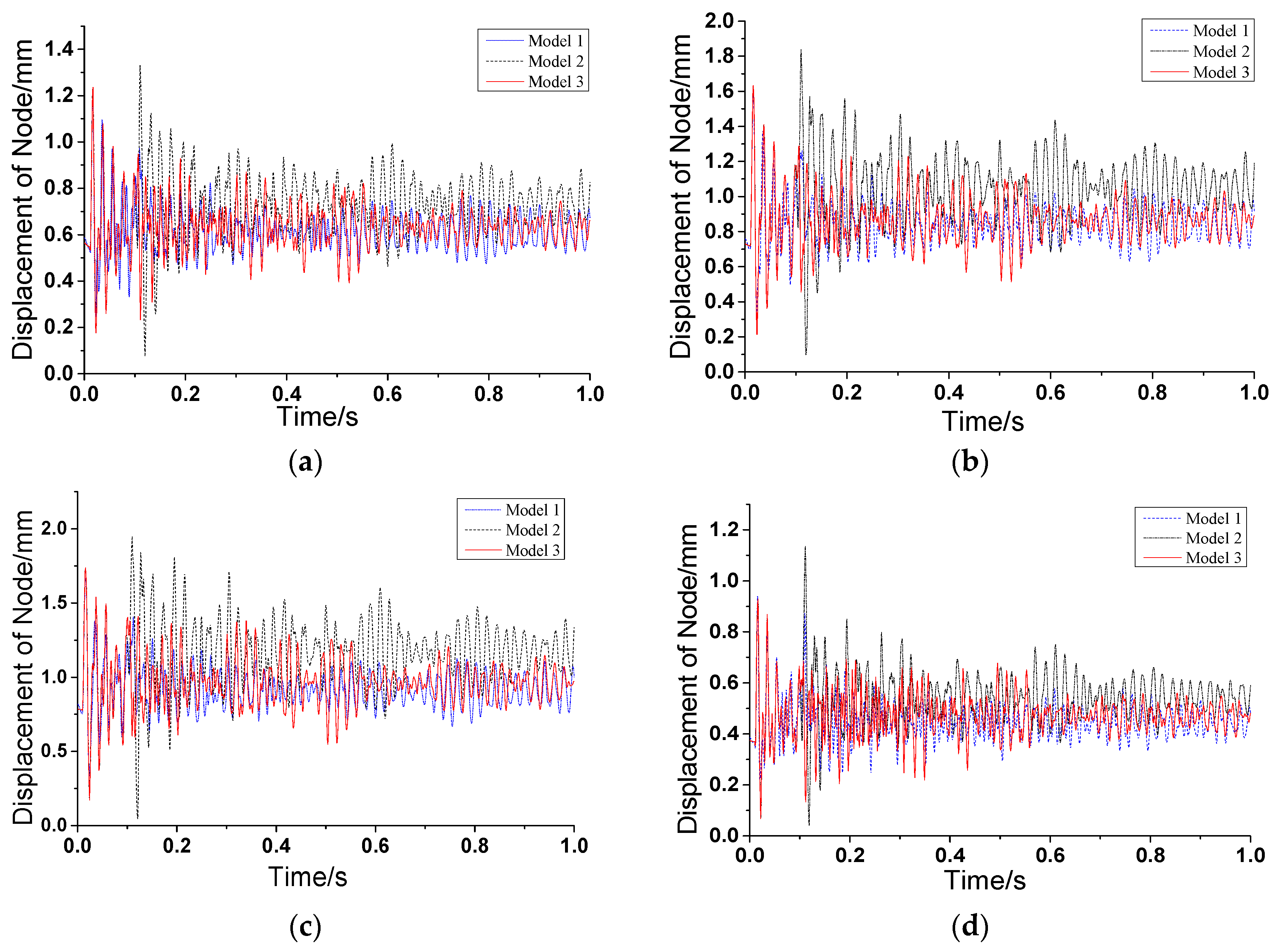
Eight nodes were selected around the impact position of the wall, as shown in Figure 10, and the displacement of each node in the models were compared, as shown in Figure 11. It can be seen that the closer the node was to the collision position, the greater the residual deformation, and the greater the amplitude of the shock. This is because the vibration of the wall is gradually weakened from the center of the impingement position to its surroundings.
It can be seen that model two has the largest amplitude of displacement and maximum residual deformation compared to model one and model three, while model one has the smallest amplitude. This is because model one has the greatest lateral stiffness among these three models, as braces are not only set at impacted walls, but also at cross walls. In addition, the rock can be stopped by the cross brace; for model two, the stiffness of the cross wall is lower than the stiffness in model one. Although it can also impede the rock, a tremendous impact that is transmitted from the brace to the cross walls lead to a larger displacement; for model three, the displacement time history curves are similar to that of model one. This does not mean it has a better performance in resisting the debris flow. In fact, in this case, the rock has penetrated through the wall and has no connection with the structure after penetration, indicating that there is no subsequent energy input. Although the nodes were shocked relatively weak, and their residual deformations are relatively small, the structure becomes unsafe if the rock crashes into the structure.
In addition, there is a lag phenomenon of the maximum displacement of the nodes in model two. On one hand, it is because the displacement is added by the collision of the rock on the cross braces. On the other hand, the stiffness of model two is lower than that of model one, because of the lack of the braces at the cross walls. This results in the large displacement after the impact on the braces. This is why the lag phenomenon does not appear in model one, but appears in model two.
4.2.3. Displacement of the Ring Beam–Structural Column Joints
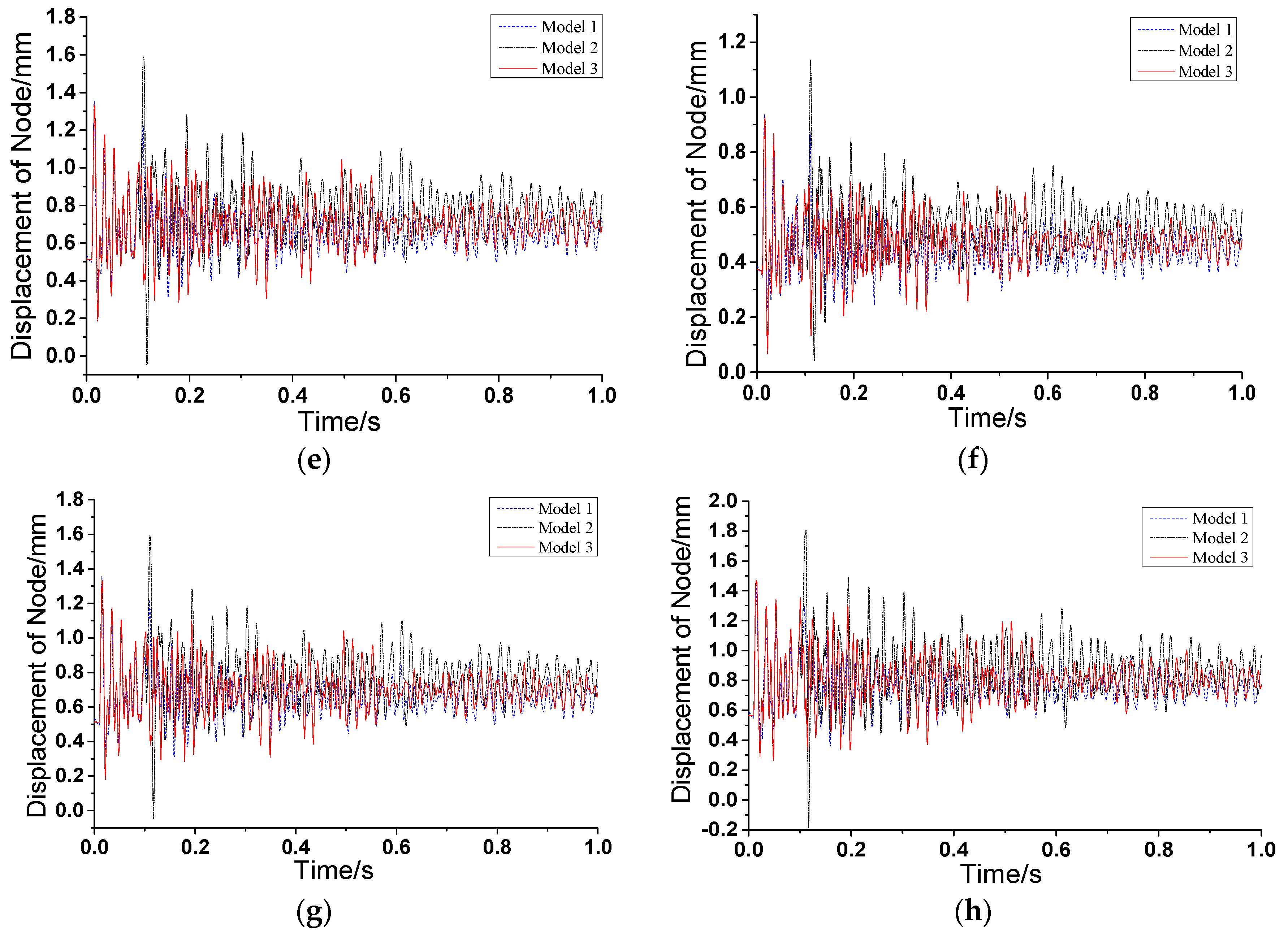
Four ring beam–structural column joints were selected, as shown in Figure 12, and the displacement of each joint in the models were compared, as shown in Figure 13. The results are similar to that of the nodes on the wall. Model two has the largest amplitude of displacement and the maximum residual deformation compared to model one and model three, while model one has the smallest and minimal residual deformation. This is because of a greater stiffness of model one, which also results in a higher vibration frequency of model one than model two. For model three, because the rock has no connection with the structure after the penetration, indicating that there is no subsequent energy input, the amplitude of displacement and maximum residual deformation are relatively low. In caveat, it is not safe if the rock crashes into the house.
From Figure 13, the same lag phenomenon of the maximum displacement of the joints in model two can also be found. The reasons are as aforementioned—the rock impacts the brace and the lateral stiffness of model two is relatively small.
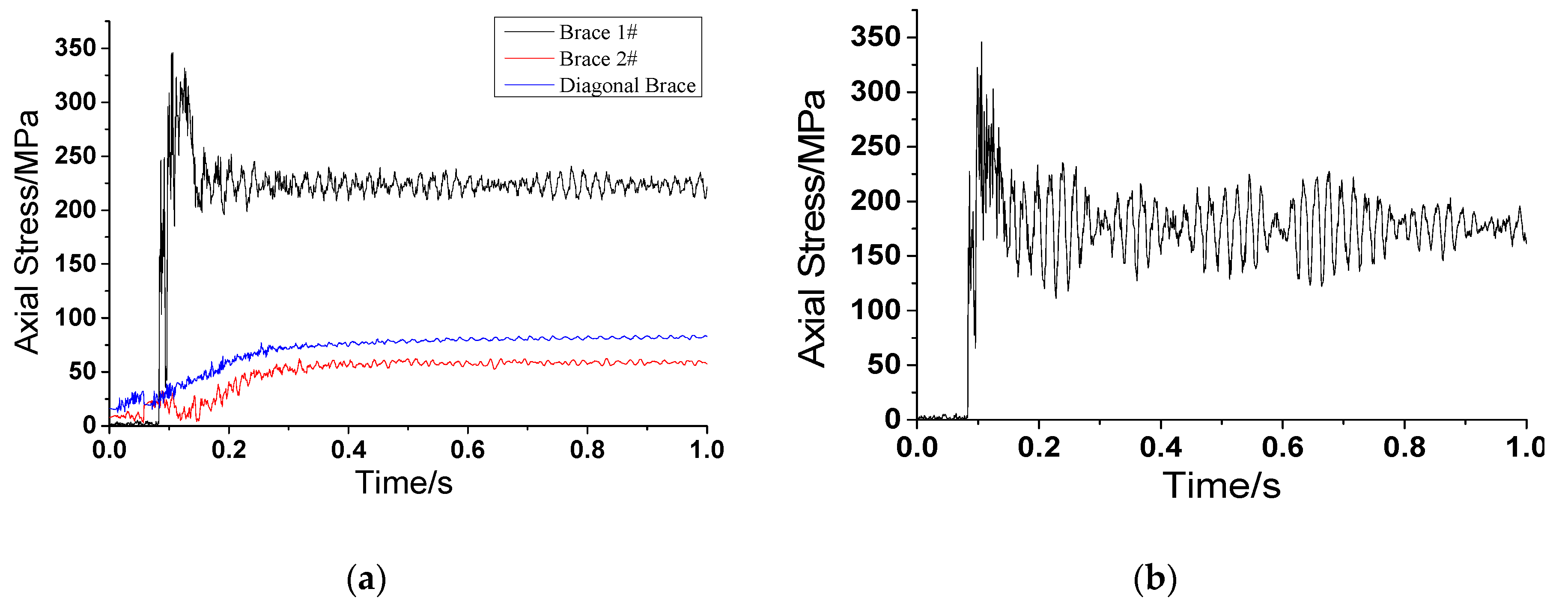
4.2.4. Axial Stress of Braces
The layouts of braces in model one can be found in Figure 7. When the collision occurs on the wall, the wall elements begin to fail and the speed of the rock is reduced. As a result, the rock impacts the center of the cross brace. For this reason, the main response modes of the brace start bending and cause tension. The impact triggers an immediate increase of axial stress and axial strain on the brace, as shown in Figure 14. The axial stress increases rapidly and reaches the yield stress when t = 0.1 s, and the peak stress is 345 MPa. Due to the rapid decrease of rock velocity, the impact force decreases gradually, and the stress is in a certain range until it becomes stable. The stress of the brace two and the diagonal brace at the cross walls are respectively 8 MPa and 16 MPa, when t = 0 s. This results from the slurry force that is loaded on the wall, as the calculation of the dynamic relaxation process determined the stress and strain produced by the static load.
As for model two, the axial stress increases rapidly and reaches the yield stress when t = 0.1 s, and the peak stress is 345 MPa. As a result, the stress falls in a certain range until it becomes stable, which is similar to model one. However, the difference is that the amplitude is much larger in model two than it is in model one. This is because of a relatively weak restraint of the supports at the ends of the impacted brace, which results from a relatively lower stiffness of the cross wall in model two.
4.3. Brief First Analysis of Some Economic and Environmental Issues
This novel structure uses a renewable material–straw brick. According to government statistics, there is more than 800 Mt of straw produced in China every year [53]. Most of straw is burnt on the fields causing heavy air pollution [54]. To solve this problem, Chinese government has promulgated regulations to prohibit this burning behavior and taken measures on straw dispose, such as using straw as feeds or fertilizer or serving as industrial raw materials. However, economic benefits brought by these methods are not comparable to those brought by using straw as construction material [55]. Besides, making full use of straw can help us saving forest resources and land resources by a declining use of woods and earth for construction.
Because of its abundance, straw is relatively cheaper than some other material. In China, it costs about 80 USD/m2 to build a house by using straw bricks, while about 150 USD/m2 by using clay bricks [56]. From the level of energy consumption in production, it demands 70 kJ/kg to make straw bricks but 3000 kJ/kg to make clay bricks [57,58]. In the aspect of transportation, because the density of a straw brick, 900 kg/m3, is smaller than that of a clay brick, 1800 kg/m3, energy-saving and emission reduction effect is obvious in transportation of straw bricks [59]. To compare the differences between straw bricks and clay bricks in building this novel structure proposed in this paper, it is assumed that these bricks are transported by a truck with capacity of 5 tones and that transportation distance is 100 km. In addition, this truck consumes 12 L of gasoline every 100 km. Based on calculation, differences between straw bricks and clay bricks in building this novel structure are shown in Table 5. From this table, when this model is discussed only, it is obvious that using straw bricks not only brings a good economic benefit but also has a positive effect on saving energy and reducing emission.
In the aspect of construction, the technique of installing steel braces and building masonry walls is mature enough that local engineers can finish construction without other professional technicians. Thus, there is no technical problems in promoting this novel structure in mountainous areas.
According to the study, losses caused by extreme climate events account of about 2.5% of GDP in China [60]. To reduce these economic losses, effective methods for disaster prevention and reduction should be carried out. This novel structure is one of these effective methods to reduce the damage and casualties caused by debris flow. Besides, this novel structure may help to comfort people in areas where geological disasters erupt frequently. Because of using novel structure, they are not forced to leave their hometown by debris flow or afraid of fatal strikes caused by these disasters. By preventing and reducing disasters, people plagued by disaster for many years can live and work in peace. Thus, steady development of society is guaranteed in those areas.
5. Proposals on Engineering Application
Based on the simulation results and discussions, some proposals of the engineering application in debris flow hazard areas are put forward as follows:
(1) For newly built structures, novel masonry structures are favorable because these structures provide an increasing capability in resisting debris flow and are more environmental friendly compared to structures with traditional masonry walls.
(2) For existing masonry structures, braces can be added to the walls to increase the stiffness to make structures perform better in regards to debris flow resistance, which is more economical than reconstruction.
(3) Establishing straw brick factories may be a great idea for local governments. It probably not only benefits the construction of novel structures in local villages where debris flow erupts frequently, but also brings a new growth point for local economy by making full use of renewable material.
(4) Local governments should give certain subsidies to extremely poor families in process of constructing or rebuilding novel structures for disaster prevention. In that way, national policy of disaster prevention and reduction can be promoted successfully, safety and property of local residents can be protected and steady development of local society can be guaranteed.
(5) The characteristics of the cross section of the steel brace should be determined by numerical simulations, which consider the debris flow load and actual environmental factors. Generally, a greater stiffness of the section results in a greater lateral stiffness of the wall. This results in more energy absorption, and hence, the braces have better performances in impeding the rock.
(6) Although the current regulations in the codes are not suitable for the design of the novel structure that is proposed in this paper directly, some regulations are referable, such as regulations about structural requirements for structural columns and ring beams. However, failure criterions demand more studies and comparisons. Here are some suggestions: failure criterions can be determined by the degree of damages to the wall, the deflection of steel braces, or when the structure collapses.
(7) Because the analysis of some economic and environmental issues is relatively brief in Section 4.3, before this anti-disaster construction, it is necessary for local governments and other researchers having a rigorous and more holistic sustainability assessment with the participation of multidisciplinary experts and using a more holistic tool such as LEED (Leadership in Energy and Environmental Design) and BREEAM (Building Research Establishment Environmental Assessment Method) or methodologies such as LCA (Life-cycle assessment) and LCC (Life Cycle Costing), etc.
6. Conclusions
A novel masonry structure was proposed in the paper, which enhanced structural stiffness by setting braces at walls to improve ability of the structure against debris flow. Main conclusions are as follows:
(1) This novel masonry structure plays an important role in disaster prevention and reduction. It can resist the impact of debris flow more effectively because of its improvement of structural rigidity and energy dissipation characteristics. It is a response to national policies and plans, which plays an active role in promoting sustainable development of society.
(2) Technically, displacement and residual deformation are small in the new masonry structure under the impact of debris flow because braces were set at walls, which contributed to stiffness of the structure. There was a lack of braces at the cross wall, which means a decrease of stiffness. This not only caused lag phenomenon of the maximum displacement, but also resulted in a large displacement. That is unfavorable to the resistance of debris flow. The impacted braces yielded under the collision. The braces at the cross wall contributed to stiffness, which strengthened restraint of the supports at the ends of impacted brace. Therefore, the amplitude of vibration of impacted brace was smaller in the novel structure. The new structure can maintain integrity, which is favorable to the transmission of impact force in terms of energy dissipation through the full use other walls and braces. Thus, the lateral displacement can be reduced, which means that the whole structure can be prevented from collapsing.
(3) In the model discussed in this paper, this novel structure is more favorable than an old structure using clay bricks in terms of cost and energy consumption. It can play an important role in promoting the sustainable development of local economy and environment.
(4) This novel masonry structure can avoid penetration of the wall under debris flow, which protects safety and property of local residents. Consequently, it may have a psychologically positive effect on people in rural, disaster-prone areas, which benefits the steady development of local society.
Acknowledgments
Financial support from the National Key Technology R&D Program through grant 2014BAL05B01 is highly appreciated.
Author Contributions
Peizhen Li conceived the new structural system and wrote the paper; Tangzhenhao Li performed the numerical study and theoretical analysis; Zheng Lu proposed the method, designed the numerical study and revised the paper; Jin Li helped to analyze the simulation results and revised the paper.
Conflicts of Interest
The authors declare no conflict of interest.
References
- Leonardi, A.; Wittel, F.K.; Mendoza, M.; Vetter, R.; Herrmann, H.J. Particle-fluid-structure interaction for debris flow impact on flexible barriers. Comput. Aided Civ. Infrastruct. Eng. 2016, 31, 323–333. [Google Scholar] [CrossRef]
- Shu, A.; Wang, L.; Zhang, X.; Ou, G.Q.; Wang, S. Study on the formation and initial transport for non-homogeneous debris flow. Water 2017, 9, 253. [Google Scholar] [CrossRef]
- Niu, C.; Wang, Q.; Chen, J.; Zhang, W.; Xu, L.; Wang, K. Hazard assessment of debris flows in the reservoir region of wudongde hydropower station in china. Sustainability 2015, 7, 15099–15118. [Google Scholar] [CrossRef]
- Zhang, W.; Wang, Q.; Chen, J.; Li, H.; Que, J.; Kong, Y. Grain-size analysis of debris flow alluvial fans in panxi area along jinsha river, china. Sustainability 2015, 7, 15219–15242. [Google Scholar] [CrossRef]
- Meng, X.J.; Hu, W.; Zhang, X.S.; Sun, P.P. Basic Characteristics, Forming reasons and risk assessment of debris flow at Daguangbao-Huangdongzi Gully, Sichuan Province. Northwest. Geol. 2014, 47, 147–156. [Google Scholar]
- Yu, B.; Yang, Y.H.; Su, Y.C.; Huang, W.J.; Wang, G.F. Research on the giant debris flow hazards in Zhouqu Country, Gansu Province on August 7, 2010. J. Eng. Geol. 2010, 18, 437–444. [Google Scholar]
- Yan, Y.; Ge, Y.G.; Zhang, J.Q.; Zeng, C. Research on the debris flow hazards in Cutou Gully, Wenchuan County on July 10, 2013. J. Catastrophol. 2014, 29, 229–859. [Google Scholar]
- Uddin, M.S.; Inaba, H.; Itakura, Y.; Kasahara, M. Estimation of the surface velocity of debris flow with computer-based spatial filtering. Appl. Opt. 1998, 37, 6234–6239. [Google Scholar] [CrossRef] [PubMed]
- Uddin, M.S.; Inaba, H.; Itakura, Y.; Yoshida, Y.; Kasahara, M. Adaptive computer-based spatial-filtering method for more accurate estimation of the surface velocity of debris flow. Appl. Opt. 1999, 38, 6714–6721. [Google Scholar] [CrossRef] [PubMed]
- Takahashi, T. Mechanical characteristics of debris flow. J. Hydraul. Div. 1978, 104, 1153–1169. [Google Scholar]
- Takahashi, T. Debris flow on prismatic open channel. J. Hydraul. Div. 1980, 106, 381–396. [Google Scholar]
- Wu, J.S.; Kang, Z.C.; Tian, L.Q.; Zhang, S.C. Research and Observation of the Debris Flow in Jiangjia Gully, Yunnan Province; Science Press: Beijing, China, 1990. [Google Scholar]
- Lanzhou Institute of Glaciology and Cryopedology; Chinese Academy of Sciences; Gansu Provincial Transportation Research Institute. Debris Flow in Gansu; China Communication Press: Beijing, China, 1982. [Google Scholar]
- Chen, G.; Wang, J.K.; Wang, L.H. Prevention Works of Debris Flow; China Railway Publishing House: Beijing, China, 1983. [Google Scholar]
- Lanzhou Institute of Glaciology and Cryopedology; Chinese Academy of Sciences; Gansu Provincial Transportation Research Institute. Highway Engineering of Debris Flow Zone; China Communication Press: Beijing, China, 1981. [Google Scholar]
- Cao, C.; Song, S.; Chen, J.; Zheng, L.; Kong, Y. An approach to predict debris flow average velocity. Water 2017, 9, 205. [Google Scholar] [CrossRef]
- Shen, S.C.; Xie, X.Q.; Xiang, X.P.; Li, L.X.; Gong, C.M.; Bai, Y.F.; Xie, X.G. Study on calculation methods of flow quantity of debris flow. China Railway Sci. 1993, 2, 80–89. [Google Scholar]
- Zhang, K. Characteristics and Control Techniques for Debris Flow in Beishan of Longnan City. Master’s Thesis, Lanzhou University, Lanzhou, China, May 2013. [Google Scholar]
- Chen, H.K.; Tang, H.M.; Wu, S.F. Research on abrasion of debris flow to high-speed drainage structure. Appl. Math. Mech. 2004, 25, 1257–1264. [Google Scholar]
- Valentino, R.; Barla, G.; Montrasio, L. Experimental analysis and micromechanical modelling of dry granular flow and impacts in laboratory flume tests. Rock Mech. Rock Eng. 2008, 41, 153–177. [Google Scholar] [CrossRef]
- Miyoshi, I.; Suzuki, M. Experimental study on impact load on a dam due to debris flow. Sabo Gakkaishi 1990, 43, 11–19. [Google Scholar]
- Chen, H.K.; Tang, H.M.; Xian, X.F.; Zhang, Y.P. Experimental model of debris flow impact features. J. Chongqing Univ. 2010, 33, 114–119. [Google Scholar] [CrossRef]
- Hu, H.K.; Wei, F.Q.; Hong, Y.; Li, X.Y. Field measurement of impact force of debris flow. Chin. J. Rock Mech. Eng. 2006, 25, 2813–2819. [Google Scholar]
- Chen, H.K.; Tang, H.M. Method to Calculate impact force and impact time of two-phase debris flow. China J. Highway Trans. 2006, 19, 19–23. [Google Scholar]
- Zhang, Y.; Wei, F.Q.; Cui, P. Destruction mode simulation of reinforced masonry structure under impact of debris flow. J. Disasters 2005, 14, 61–67. [Google Scholar]
- Zhang, Y.; Wei, F.Q.; Jia, S.W.; Liu, B. Experimental research of unreinforced masonry wall under dynamic impact of debris flow. J. Mt. Sci. 2006, 24, 340–345. [Google Scholar]
- Cheng, X.; Wang, J.; Ren, Y. Fluid–solid interaction dynamic response of masonry structures under debris flow action. Eur. J. Environ. Civ. Eng. 2013, 17, 841–859. [Google Scholar] [CrossRef]
- Yang, S.Q. Introduction of “National Comprehensive Disaster Prevention and Reduction Plan”. Disaster Reduct. China 2017, 1, 20–22. [Google Scholar]
- Institute of Mountain Hazards and Environment; Chinese Academy of Sciences. Debris Flow in China; The Commercial Press: Beijing, China, 2000. [Google Scholar]
- Lu, Z.; Yang, Y.; Lu, X.; Liu, C. Preliminary study on the damping effect of a lateral damping buffer under a debris flow load. Appl. Sci. 2017, 7, 201. [Google Scholar] [CrossRef]
- Di, P.; Ji, J.; Liu, L.D. Application of straw energy-saving wall. Ind. Constr. 2011, 41, 57–59. [Google Scholar]
- Wight, G.D.; Ingham, J.M.; Wilton, A.R. Innovative seismic design of a post-tensioned concrete masonry house. Can. J. Civ. Eng. 2007, 34, 1393–1402. [Google Scholar] [CrossRef]
- Luciano, R.; Sacco, E. Damage of masonry panels reinforced by FRP sheets. Int. J. Solids Struct. 1998, 35, 1723–1741. [Google Scholar] [CrossRef]
- Kiss, R.M.; Kollar, L.P.; Jai, J.; Krawinkler, H. Masonry strengthened with FRP subjected to combined bending and compression, part ii: Test results and model predictions. J. Compos. Mater. 2002, 36, 1049–1063. [Google Scholar] [CrossRef]
- Gattesco, N.; Amadio, C.; Bedon, C. Experimental and numerical study on the shear behavior of stone masonry walls strengthened with GFRP reinforced mortar coating and steel-cord reinforced repointing. Eng. Struct. 2015, 90, 143–157. [Google Scholar] [CrossRef]
- Chen, H. Study on Seismic Performance of RC Frame Structure in Hospital Building Reinforced with Steel Brace. Master’s Thesis, China University of Mining and Technology, Xuzhou, China, June 2016. [Google Scholar]
- Khan, D.; Rawat, A. Nonlinear seismic analysis of masonry infill RC buildings with eccentric bracings at soft storey level. Procedia Eng. 2016, 161, 9–17. [Google Scholar] [CrossRef]
- Varum, H.; Teixeira-Dias, F.; Marques, P.; Pinto, A.V.; Bhatti, A.Q. Performance evaluation of retrofitting strategies for non-seismically designed RC buildings using steel braces. Bull. Earthq. Eng. 2013, 11, 1129–1156. [Google Scholar] [CrossRef]
- Laigle, D.; Lachamp, P.; Naaim, M. Sph-based numerical investigation of mudflow and other complex fluid flow interactions with structures. Comput. Geosci. 2007, 11, 297–306. [Google Scholar] [CrossRef]
- Elhamdouni, Y.; Khabbazi, A.; Benayad, C.; Mounir, S.; Dadi, A. Thermophysical and mechanical characterization of clay bricks reinforced by alfa or straw fibers. IOP Conf. Ser. Mater. Sci. Eng. 2017, 186, 012035. [Google Scholar] [CrossRef]
- Chalco Vera, J.; Valeiro, A.; Posse, G.; Acreche, M.M. To burn or not to burn: The question of straw burning and nitrogen fertilization effect on nitrous oxide emissions in sugarcane. Sci. Total Environ. 2017, 587, 399–406. [Google Scholar] [CrossRef] [PubMed]
- Tang, J.B.; Hu, K.H.; Zhou, G.D.; Chen, H.Y.; Zhu, X.H.; Ma, C. Debris flow impact pressure signal processing by the wavelet analysis. J. Sichuan Univ. 2013, 45, 8–13. [Google Scholar]
- Watanabe, M.; Ikeya, H. Investigation and analysis of volcanic mud flows on Mount Sakurajima, Japan. Eros. Sediment Trans. Meas. 1981, 33, 245–256. [Google Scholar]
- Lo, D.O.K. Review of Natural Terrain Landslide Debris-Resting Barrier Design. Available online: http://ebook.lib.hku.hk/HKG/B35846604.pdf (accessed on 17 June 2002).
- Zhang, S. A comprehensive approach to the observation and prevention of debris flow in China. Nat. Hazards 1993, 7, 1–23. [Google Scholar] [CrossRef]
- LS-DYNA Theoretical Manual. Livermore Software Technology Corporation, May 2007. Available online: http://ftp.lstc.com/anonymous/outgoing/jday/manuals/ls-dyna_971_manual_k_rev1.pdf (accessed on 17 August 2009).
- Yang, H.J.; Wei, F.Q.; Hu, K.H.; Hong, Y. Experimental study on vertical sorting of particles in debris flow with impact signals. J. Catastr. 2011, 26, 29–34. [Google Scholar]
- He, N.; Chen, N.S.; Zeng, C. Current situation and tendencies of debris flow initiation mechanism. J. Catastr. 2013, 28, 121–125. [Google Scholar]
- Ikeya, H. Debris flow and its countermeasures in Japan. Bull. Eng. Geol. Environ. 1989, 40, 15–23. [Google Scholar] [CrossRef]
- Govindjee, S.; Kay, G.J.; Juan, C.S. Anisotropic modelling and numerical simulation of brittle damage in concrete. Int. J. Numer. Methods Eng. 1995, 38, 3611–3633. [Google Scholar] [CrossRef]
- Eurocode Committee for Standardization. Eurocode 2—Design of Concrete Structures; Springer: Berlin, Germany, 2014. [Google Scholar]
- Cowper, G.R.; Symonds, P.S. Strain hardening and strain rate effect in the impact loading of cantilever beams. Brown Univ. Appl. Math. Rep. 1957, 31, 235–263. [Google Scholar]
- Zhang, J.; Wang, J.; Guo, S.; Wei, B.; He, X.; Sun, J.; Shu, S. Study on heat transfer characteristics of straw block wall in solar greenhouse. Energy Build. 2017, 139, 91–100. [Google Scholar] [CrossRef]
- Ding, M.; Liu, Z.Y.; Ding, Y.G. The study of test method on pollution prevention of straw building in the Jiangsu province. Adm. Technol. Environ. Monit. 2012, 24, 72–74. [Google Scholar]
- Luo, L. Study on straws recycle efficiency. J. Sichuan Norm. Univ. (Nat. Sci.) 2011, 34, 911–914. [Google Scholar]
- Song, W. Application of straw structures in rural area in China. China Homes 2013, 7, 103–104. [Google Scholar]
- Zhang, L.L.; Bao, J.F. The development and application of new environmental protection and energy-saving material straw. Energy Sav. Mater. 2007, 4, 38–39. [Google Scholar]
- Yang, Q.X. Economic Benefit Analysis of Green Building Materials: A Case Study of AAC Block. Master’s Thesis, Jiangxi University of Science Technology, Nanchang, China, June 2012. [Google Scholar]
- Ministry of Housing and Urban-Rural Construction of the People’s Republic of China. Load Code for the Design of Building Structures GB 5009-2012; China Architecture & Building Press: Beijing, China, 2012.
- Chen, L. Fast construction of flood control, drought prevention and disaster reduction systems in China; Comprehensively improvement of the ability to control floods and droughts in China. China Water Resour. 2009, 9, 1–2. [Google Scholar]
Figure 1.
Damages caused by debris flow: (a) Debris flow in Zhouqu County; (b) a masonry wall destroyed by debris flow.
Figure 1.
Damages caused by debris flow: (a) Debris flow in Zhouqu County; (b) a masonry wall destroyed by debris flow.

Figure 2.
Impact force pulse modes of common debris flows: (a) sawtooth pulse mode; (b) rectangular pulse mode; (c) spike pulse mode.
Figure 2.
Impact force pulse modes of common debris flows: (a) sawtooth pulse mode; (b) rectangular pulse mode; (c) spike pulse mode.

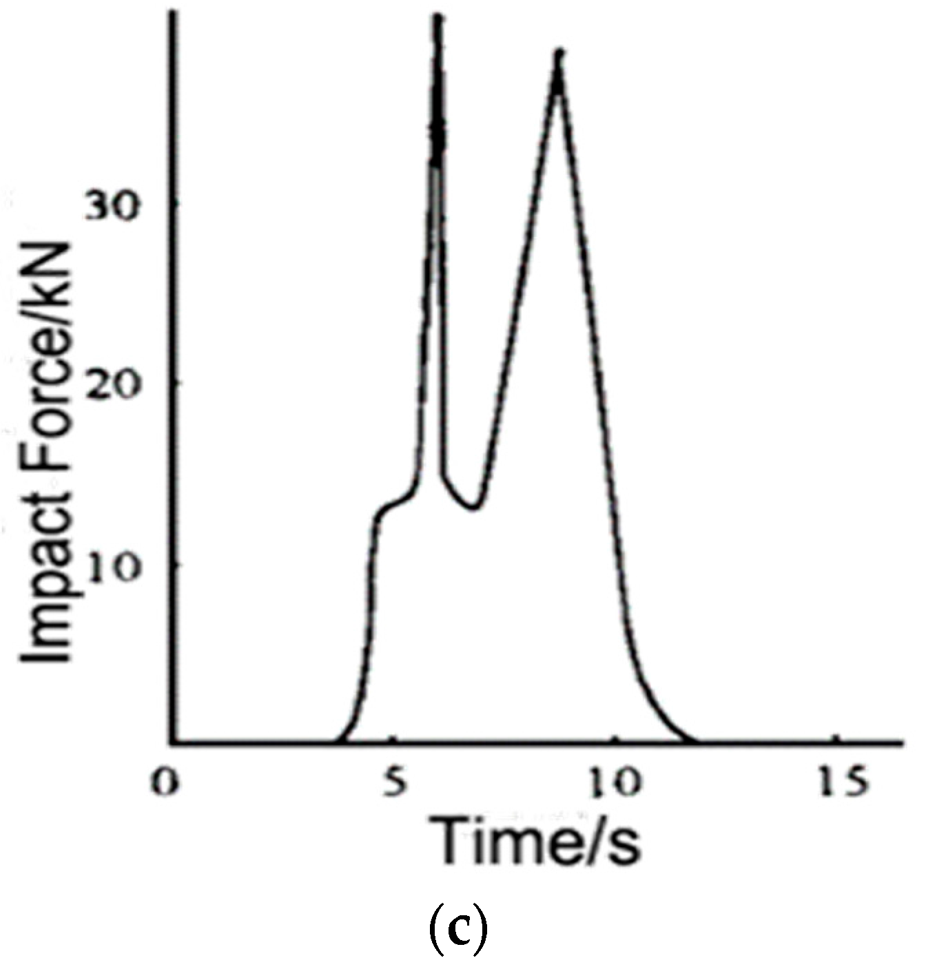
Figure 3.
The conceptual plan of the novel masonry structure.

Figure 4.
General view of the rock’s impact position.

Figure 5.
Layouts of the model: (a) First floor; (b) second floor.
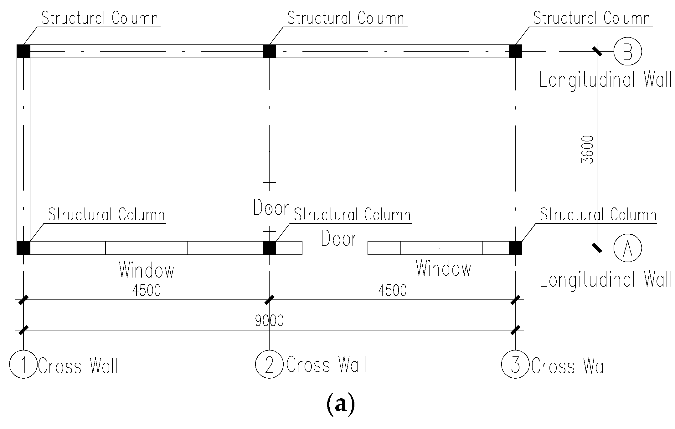

Figure 6.
Sketch map of the masonry structure.

Figure 7.
Structural layouts of model 1: (a) First floor; (b) section 1–1; (c) section 2–2; (d) section 3–3.
Figure 7.
Structural layouts of model 1: (a) First floor; (b) section 1–1; (c) section 2–2; (d) section 3–3.


Figure 8.
The results of dynamic relaxation analysis of the walls at axis B in model 1: (a) Stress; (b) displacement in the Y direction.
Figure 8.
The results of dynamic relaxation analysis of the walls at axis B in model 1: (a) Stress; (b) displacement in the Y direction.


Figure 9.
The impact force of the three models: (a) Model one; (b) model two; (c) model three.


Figure 10.
Eight representative nodes in the wall.
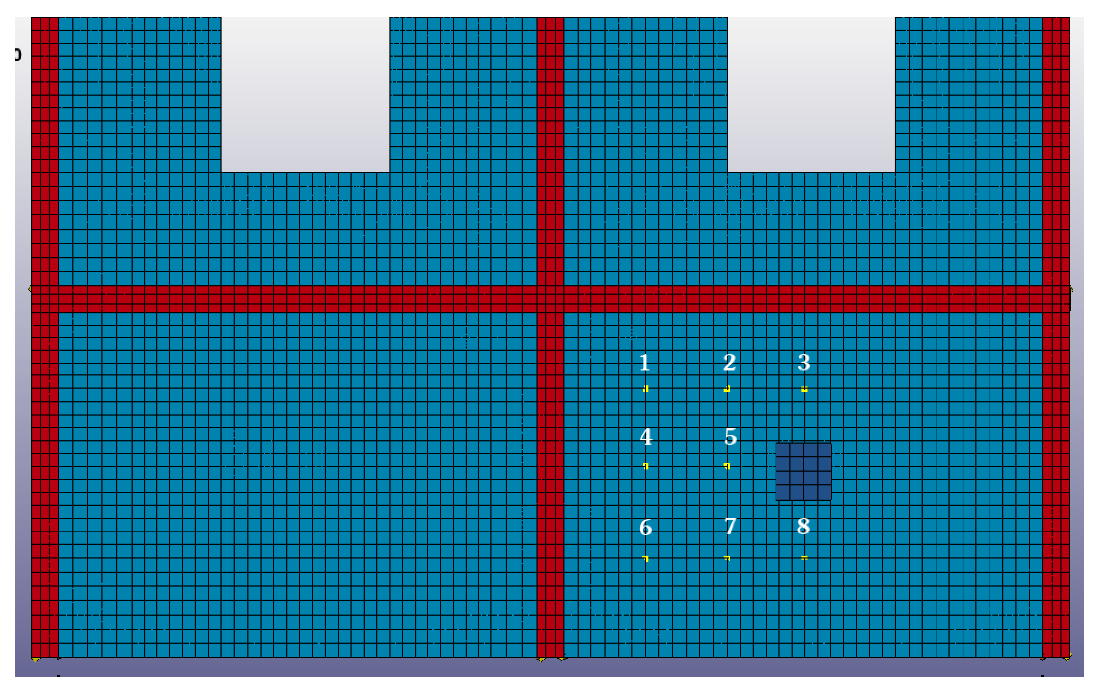
Figure 11.
Displacement time history curve: (a) Node one; (b) node two; (c) node three; (d) node four; (e) node five; (f) node six; (g) node seven; (h) node eight.
Figure 11.
Displacement time history curve: (a) Node one; (b) node two; (c) node three; (d) node four; (e) node five; (f) node six; (g) node seven; (h) node eight.


Figure 12.
The ring beam–structural column joints.
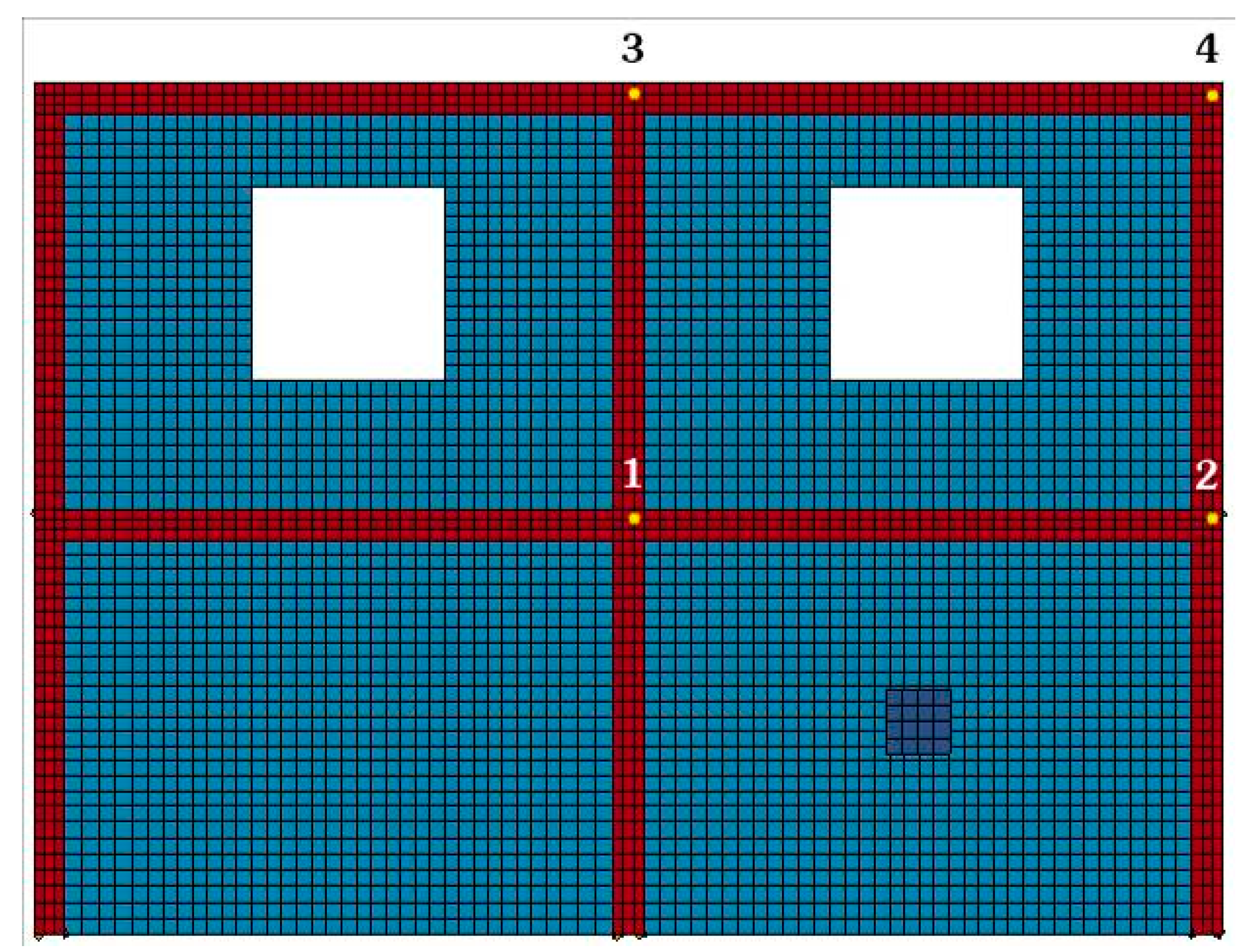
Figure 13.
Displacement time history curve: (a) Joint one; (b) joint two; (c) joint three; (d) joint four.
Figure 13.
Displacement time history curve: (a) Joint one; (b) joint two; (c) joint three; (d) joint four.

Figure 14.
Stress time history curve of the braces: (a) Model one; (b) model two.


Table 1.
Empirical formulas of debris flow velocity.
| Area | Formula | Range of Uses |
|---|---|---|
| Dongchuan Viscous Debris Flow | Suitable for viscous debris flow, especially for those in the area of Dongchuan | |
| Wudu Viscous Debris Flow Formula | Suitable for viscous debris flow in Wudu | |
| Beijing Watery Debris Flow | Suitable for watery debris flow in Beijing | |
| Zhamalong Watery Debris Flow | Suitable for watery debris flow with longitudinal slopes between 0.07 and 0.13 in Zhamalong |
Table 2.
The parameters of hydrodynamic pressure of the slurry.
| Type of Debris Flow | Density (t/m3) | Hydrodynamic Head Empirical Coefficient | Stationary Stage Empirical Coefficient |
|---|---|---|---|
| Viscous debris flow | 2.0 | 3 | 0.5 |
Table 3.
Masonry material parameters.
| Density | Poisson Ratio | Straw Brick Compressive Strength | Mortar Strength | Masonry Compressive Strength | Elastic Modulus |
|---|---|---|---|---|---|
| 1500 kg/m3 | 0.15 | 15.0 MPa | 10 MPa | 2.31 MPa | 3.70 GPa |
Table 4.
The peak value of the impact force of the rock.
| Model | Peak Force at Walls/kN | Peak Force at Braces/kN |
|---|---|---|
| 1 | 218.0 | 83.6 |
| 2 | 216.3 | 54.2 |
| 3 | 216.5 | — |
Table 5.
Analogy between Straw Bricks and Clay Bricks in building this novel structure.
| Items | Straw Bricks | Clay Bricks |
|---|---|---|
| Cost (USD) | 5184 | 9720 |
| Energy consumption in production (106 kJ) | 2.5 | 215.6 |
| Energy consumption in transportation (103 kJ) | 6.1 | 11.4 |
© 2017 by the authors. Licensee MDPI, Basel, Switzerland. This article is an open access article distributed under the terms and conditions of the Creative Commons Attribution (CC BY) license (http://creativecommons.org/licenses/by/4.0/).
Share and Cite
MDPI and ACS Style
Li, P.; Li, T.; Lu, Z.; Li, J. Study on Dynamic Response of Novel Masonry Structures Impacted by Debris Flow. Sustainability 2017, 9, 1122. https://doi.org/10.3390/su9071122
AMA Style
Li P, Li T, Lu Z, Li J. Study on Dynamic Response of Novel Masonry Structures Impacted by Debris Flow. Sustainability. 2017; 9(7):1122. https://doi.org/10.3390/su9071122
Chicago/Turabian StyleLi, Peizhen, Tangzhenhao Li, Zheng Lu, and Jin Li. 2017. "Study on Dynamic Response of Novel Masonry Structures Impacted by Debris Flow" Sustainability 9, no. 7: 1122. https://doi.org/10.3390/su9071122
Note that from the first issue of 2016, this journal uses article numbers instead of page numbers. See further details here.