Article

Virtual Inertia Control-Based Model Predictive Control for Microgrid Frequency Stabilization Considering High Renewable Energy Integration

by
Thongchart Kerdphol
1,*,
Fathin S. Rahman
1,
Yasunori Mitani
1,
Komsan Hongesombut
2 and
Sinan Küfeoğlu
3
1
Department of Electrical and Electronics Engineering, Kyushu Institute of Technology, Fukuoka 804-0093, Japan
2
Department of Electrical Engineering, Kasetsart University, Bangkok 10900, Thailand
3
Department of Electrical Engineering, Aalto University, Espoo 02150, Finland
*
Author to whom correspondence should be addressed.
Sustainability 2017, 9(5), 773; https://doi.org/10.3390/su9050773
Submission received: 9 March 2017 / Revised: 27 April 2017 / Accepted: 3 May 2017 / Published: 8 May 2017
(This article belongs to the Special Issue Smart Grid)

Abstract

:
Renewable energy sources (RESs), such as wind and solar generations, equip inverters to connect to the microgrids. These inverters do not have any rotating mass, thus lowering the overall system inertia. This low system inertia issue could affect the microgrid stability and resiliency in the situation of uncertainties. Today’s microgrids will become unstable if the capacity of RESs become larger and larger, leading to the weakening of microgrid stability and resilience. This paper addresses a new concept of a microgrid control incorporating a virtual inertia system based on the model predictive control (MPC) to emulate virtual inertia into the microgrid control loop, thus stabilizing microgrid frequency during high penetration of RESs. The additional controller of virtual inertia is applied to the microgrid, employing MPC with virtual inertia response. System modeling and simulations are carried out using MATLAB/Simulink® software. The simulation results confirm the superior robustness and frequency stabilization effect of the proposed MPC-based virtual inertia control in comparison to the fuzzy logic system and conventional virtual inertia control in a system with high integration of RESs. The proposed MPC-based virtual inertia control is able to improve the robustness and frequency stabilization of the microgrid effectively.

1. Introduction

Widespread growth in utilizing renewable energy sources (RESs), such as wind, solar, biomass, and geothermal for electricity generation has become unavoidable. These are emerging as an important constituent of small-scale power systems called microgrids [1]. A microgrid is a group of local grids with a number of RESs, energy storage, and domestic loads, which can be identified as an independent system with the capability to operate in either grid-connected or isolated mode, thus reducing a huge burden on the utility grids [2,3]. However, RESs exchange power to the microgrids through inverters/converters. The power electronic interface-based RESs will reduce the overall system inertia and cause lack of frequency/voltage stabilization to a microgrid compared with traditional synchronous generators [4]. These negative effects in using power electronics, along with the intermittent nature of most RESs, could lead to problems such as severe power generation fluctuations due to variable nature of high RESs, voltage rise issues due to reverse power flow from high RESs, and excessive supply of electricity in the power grid due to full generation by high RESs. These issues result in the difficulty to stabilize system frequency and voltage, leading to the weakening of microgrid resiliency. In order to handle the drawback introduced by inverter-based generators in microgrids, one of the modern solutions is to emulate the behavior of synchronous generators virtually into the microgrid, thus improving the system stability and resiliency [5].
The modern solution is known as a virtual synchronous machine/generator (VSM, VISMA, and VSG) concept, which emulates the essential behavior of a synchronous machine while providing ancillary services to systems [6,7]. Virtual inertia control is a particular case of VSG implementation, where only the action of the prime mover is emulated to support frequency control. The strategy is based on the rate of change of frequency (RoCoF). It calculates the frequency deviation to add the extra active power to the set-point. Thus, this concept emulates the inertia characteristic, which contributes to the total inertia of the microgrid, enhancing the transient frequency stability. During the past years, several models have been proposed and investigated related to the virtual inertia control designs. Li et al. [6] proposed a coherency-based equivalence method for VSG control using modular multilevel converter to emulate behaviors of the synchronous generator. Liu et al. [7] performed the comparison of dynamic characteristics between the VSG method and droop control method to emulate virtual inertia into power system. Chen et al. [8] presented the investigation of VSG for the islanding area, such as a microgrid system. Beck et al. [9] applied an energy storage system to perform a similar role as the kinetic energy in the rotor of a synchronous generator for improving the dynamic stability of power system. Karapanos et al. [10] proposed and studied the effect of VSG connected with the utility grid. Zhong et al. [11] presented the VSG controller based on the swing equation with the objective of conducting the inverter frequency reference.
In [6,7,8,9,10,11], most research focused on the design and implementation of VSG in the area of power electronics (i.e., equipment and control scales) without considering the effect of high penetration of RESs. During high penetration of RESs and load disturbances, the virtual inertia/VSG control might be unstable, leading to instability and system collapse. This issue is the major drawback of the mentioned approaches. Without considering this significant effect, the previous virtual inertia designs and techniques might be insufficient for microgrids. Hence, a robust adaptive control method needs to be implemented together with the virtual inertia control to deal with changes in a microgrid with high RES penetration.
Up to now, robust adaptive control techniques have been developed to deal with changes in system parameters. Fuzzy logic systems have been applied in research on frequency control with and without nonlinearities [12]. The applications of neural networks, genetic algorithm, and optimal control for frequency control have been reported in [13,14,15]. Compared with the mentioned methods, the model predictive control (MPC) shows the finest performance, such as fast response and robustness against load disturbances and parameter uncertainty. MPC is an advanced control strategy that has been widely used in industry. It adopts an optimization method to calculate the optimal control actions at each sampling time to system constraints. MPC is also well adapted to different physical setups and it allows for a unified method [16,17]. In power generation control area, MPC is applied to thermal power plant coordinated control [18] and nuclear power plant control [19,20]. In frequency control area, Mohamed et al. [21] proposed MPC designed for a multi-area power system and Mohamed et al. [22] presented a multi-area system considering integration of wind turbines. Pahasa and Ngamroo [23] proposed the coordinated control of wind turbines and plug-in electric vehicles using MPC for microgrid frequency control. Pahasa and Ngamroo [24] applied the charging/discharging of plug-in electric vehicles based on MPC for frequency stabilization. To overcome the difficulties in high penetration of RESs/load and mismatch parameters of the microgrid generations, this paper proposes virtual inertia control based on MPC to achieve a more stable and robust microgrid frequency stability and performance, avoiding instability and system collapse.
This paper presents a novel adaptive control method based on virtual inertia system with MPC for microgrid frequency stabilization by emulating virtual inertia into the microgrid during high penetration of RES and load uncertainties. The additional controller of virtual inertia control is applied to the microgrid, employing MPC with virtual inertia response. System modeling and simulations are carried out using MATLAB/Simulink®. The simulation results confirm the superior robustness and frequency stabilization effect of the proposed MPC-based virtual inertia control in comparison to the fuzzy logic system and conventional virtual inertia control. The main contribution of this work is that using the proposed method, the microgrid system can be smoothly stabilized, maintained, and prevented from instability and collapse during high integrations of RES/load and mismatch parameters of microgrid generations. The rest of this paper is organized as follows: a brief introduction to microgrid frequency control considering virtual inertia system is given in Section 2. In Section 3, the proposed MPC-based virtual inertia control is presented. Section 4 introduces the fuzzy logic design for virtual inertia control as a comparative intelligent method. Section 5 presents four case studies of the proposed MPC-based virtual inertia control and the time-domain simulated results. Microgrid frequency performance under various operating conditions is presented. Finally, the conclusion is given in Section 6.

2. System Overview and Modeling

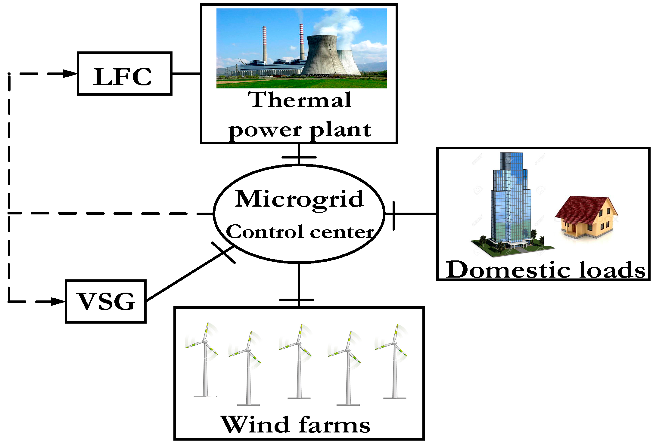
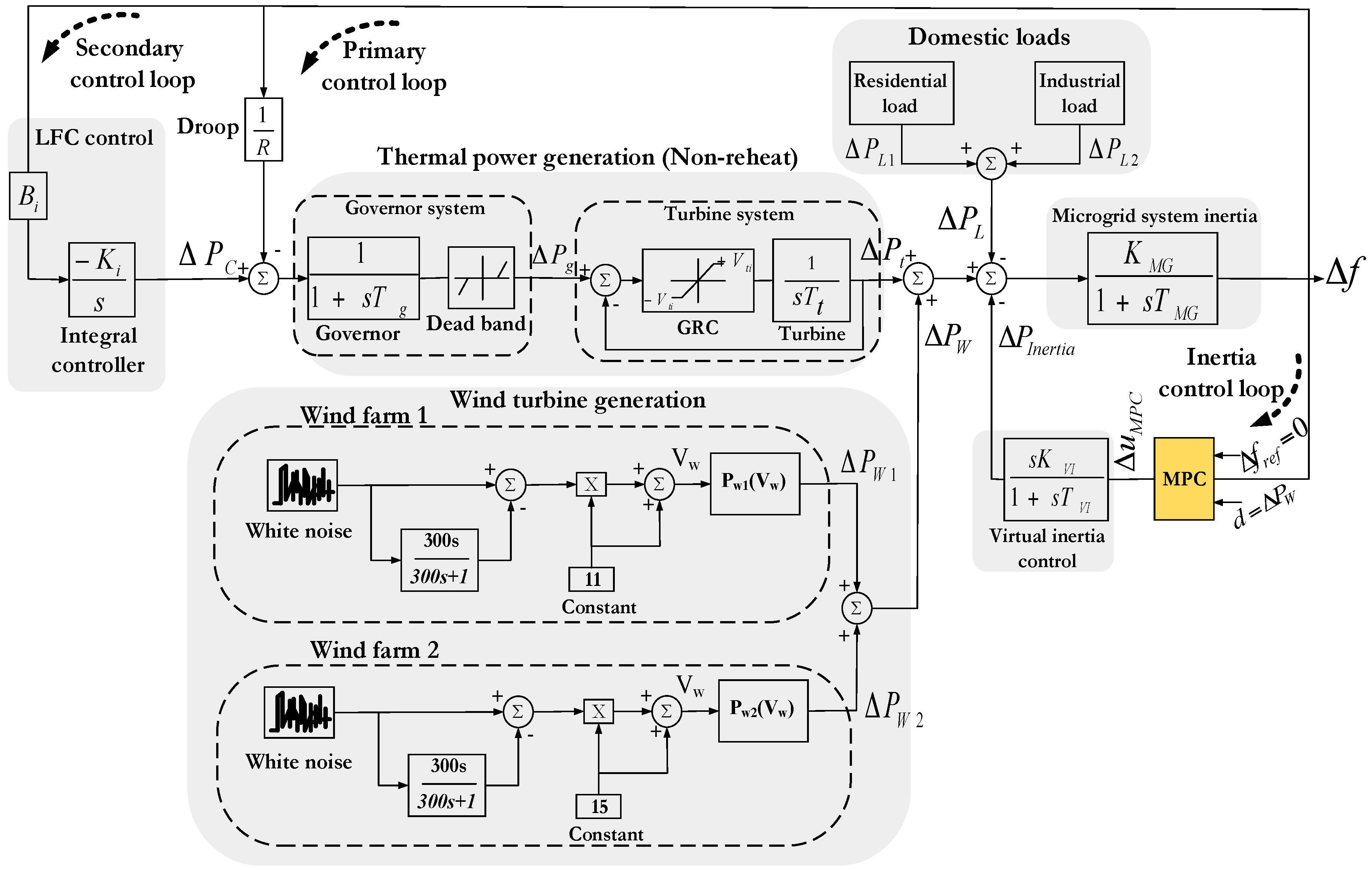
2.1. Microgrid System

The microgrid system employed in this research is displayed in Figure 1. System details are shown as follows: thermal power plant with a peak power of 20 MW, wind farm 1 with a peak power of 2.5 MW, wind farm 2 with a peak power of 8 MW, residential load with a peak power of 5 MW, and industrial load with a peak power of 10 MW. The system base is 20 MW [25]. Due to the penetration of RESs such as wind turbine generation in the microgrid, these power electronics-based RESs reduce overall system inertia and are negatively affecting frequency and voltage stabilization of the microgrid. The virtual inertia system is greatly expected to compensate active power imbalance in the microgrid together with the LFC or when the LFC is not sufficient.
The non-linear model of the studied microgrid is shown in Figure 2. To get an accurate perception of the actual microgrid, this paper considers the important inherent requirements and the basic constraints imposed by the physical system dynamics of thermal power system, wind power system, and load system. An important physical constraint of thermal power plant is the rate of change of power generation due to the limitation of thermal and mechanical movements. The physical system dynamics of the thermal generation is represented by the speed governor dead band and generation rate constraint (GRC). The maximum value of dead band for the governor of the steam turbine is specified as 0.05 pu. The GRC for non-reheat thermal generation is specified as 10% per minute [22]. The VU and VL are the maximum and minimum limits that restrict the rate of valve (gate) closing/opening speed. The physical system dynamic of the load is described in Appendix A. Then, the wind power and load demand are assigned as the disturbance to the microgrid. In the virtual inertia model, the first-order derivative transfer function with gain (KVI) and time delay (TVI) is employed [26]. The important physical constraint of the virtual inertia system is described in the following section. Microgrid system parameters are shown in Table 1 [27,28].

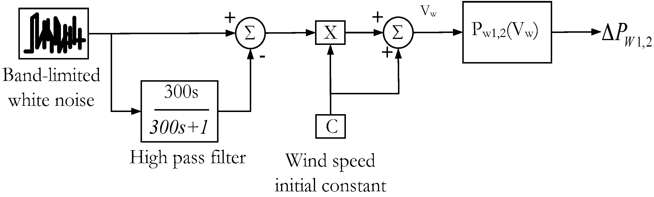
2.2. Wind Turbine Generation

The model of wind turbine generation for frequency control is described in Figure 3. In this study, the wind speed standard deviation is multiplied by the random output fluctuation delivered from the white noise block in MATLAB/Simulink® in order to evaluate the random wind power fluctuation in the microgrid as shown in Figure 11 [29,30]. Wind power output PW1,2 can be calculated as follows:
P W 1 , 2 = 1 2 C p V W 3 d A

2.3. Frequency Control Based on Inertia Response

Frequency control is characterized by two main processes the inertia response process and primary control process. During the inertia response process, the controllers have not yet been activated, hence, when a frequency deviation occurs, the power requirement is balanced by the kinetic energy from the generators. During the second process, primary control stabilizes frequency to a new steady-state condition for a time period between 10 and 30 s after the disturbance. Afterwards, the secondary control, such as load frequency control (LFC), recovers frequency to its nominal equilibrium stage for a time period between 30 s and 30 min after the disturbance [31].
In conventional power systems, the inertia response is represented by the kinetic energy. The total kinetic energy of a system rotational mass, including spinning loads, is expressed as [32,33]:
E k i n e t i c = 1 2 J ω 2
The rate of change of rotor speed relies on the torque balance of spinning mass as shown below.
T m T e = P m ω P e ω = J d ω d t
The stored kinetic energy (Ekinetic) is regularly characterized proportional to its power rating and known as the system inertia constant (H):
H = E k i n e t i c S
Therefore, the rate of change of frequency (RoCoF) can be obtained and calculated as follows [11]:
d ω d t = ω 2 ( T m T e ) 2 H S
In the per-unit system, the RoCoF can be represented as:
d ω d t = ( P m P e ) 2 H S

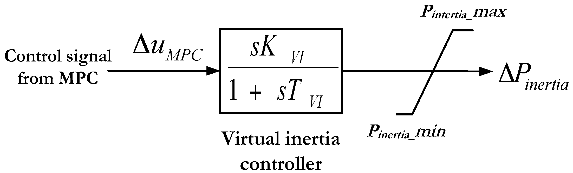
2.4. Virtual Inertia Control for Microgrids

Virtual inertia control is a particular case of a VSM/VISMA/VSG implementation, where only the action of the prime mover is emulated to support frequency control systems [5]. The virtual inertia control strategy is based on the rate of change of frequency (RoCoF). It calculates the frequency deviation to add extra active power to the set-point. As mentioned before, the renewable energy sources (RESs) in a microgrid such as wind and solar generations equip inverters to connect to the grid. Utilization of these power electronic inverters reduces overall system inertia, affecting the microgrid stability and resiliency and increases the uncertainties in the system. The shortage of inertia response from RESs in a microgrid can be solved by adding the virtual inertia control block as shown in Figure 2. The power of virtual inertia block is obtained by deploying energy storage systems (ESS). In this way, RESs could give the inertia support to the microgrid similar to the conventional synchronous generator, enhancing the transient frequency stability, resilience [6] and reliability [34].
The microgrid inertia constant (H) is determined by Equation (7) with the unit of puMW s, where f0 is the nominal frequency (i.e., 60 Hz) and D is the load-damping coefficient.
T M G = M D = 2 H f 0 D
where
D = 1 K M G
M = 2 H f 0
The inertia power is obtained by determining RoCoF. For any frequency deviation, the virtual inertial controller provides the required power to the microgrid as shown below.
Δ P i n e r t i a = K V I d ( Δ f ) d t
In this study, KVI is the virtual inertia variable gain due to the RESs/load changes. The value of 0.08 is used, obtained using trial-and-error method. It yielded a good dynamic stability during the transients even when the total system inertia is reduced to 50% of its system. Figure 4 shows the virtual inertia power control using the MPC control signal. In the virtual inertia controller model, the first-order derivative transfer function with the gain and time delay is used [26].

3. Model Predictive Control Design

MPC has confirmed to have a high control efficiency in a wide range of industry applications such as chemical process, petrol industry, electromechanical systems, and several other applications including power system controls [35]. The MPC method is based on an explicit use of a prediction model of the system response in order to obtain the control actions by minimizing an objective function. The effectiveness of the MPC is demonstrated to be equivalent to the optimum control. The objective of the MPC is to evaluate a sequence of control movements to the set point in an optimum manner. The general concept of MPC is shown in Figure 5, where y is the actual output, y ¯ is the predicted output, and u is the manipulated input. At the present sampling instant, known as j, the MPC scheme determines a set of M values of the input {u(j + i − 1), i = 1, 2, …, M}. The set contains current input u(j) and M − 1 future inputs. The input is set constant after the M control moves. The input are determined in order that a set of P predicted outputs { y ¯ (j + i), i = 1, 2, …, P} achieves the set point in an optimum control manner [24,36].
The number of predictions P is based on the prediction horizon, whereas the number of M control moves is called the control horizon. Even if a sequence of M control moves is determined at each sampling instant, only the first move has been applied. Afterwards, a new sequence is calculated at the next sampling instant; after new measurements become available again, only the first input movement is implemented. The process is repeated at each sampling instant.
The MPC predictions are created by the dynamic model, known as a linear empirical model (e.g., multivariable version of the step response or difference equation models). Alternatively, a transfer function or state-space models can be applied.
The MPC technique solves an optimization problem for finite future time steps at current time [19]. Thus, the system can be expressed by its finite impulse response [37] as:
y ( j + 1 ) = y ( j ) + A i = 0 n T δ i u ( j i )
The coefficient number is presented as:
δ i = g i + 1 g i , i = 0 , ... , n T
where gi is the scalar such that giA is the ith impulse response coefficient matrix.
The MPC problem is to calculate u(j) as the solution to the quadratic program, which is defined as [36]:
min u ( j ) Z h M [ y ( j + h ) r ( j + h ) ] T W y [ ( y ( j + h ) r ( j + h ) ) ] + [ u ( j ) u ( j 1 ) ] T W u [ u ( j ) u ( j 1 ) ]
Subject to:
y ( j + 1 ) = y ( j ) + A i = 0 n T δ i u ( j i ) Δ u max + u ( j + 1 u ( j ) Δ u max + u ( j 1 ) )
Each weight (i.e., Wy and Wu) is assumed to be constant multiplied by the identity matrix, which is suitable for the virtual inertia control. This is because the weighting of the input (i.e., frequency deviation) and output (i.e., virtual inertia power control signal) may not change when the microgrid parameters, wind power, and load power are changed.
In addition, two simple PI or fuzzy controllers may be sufficient for virtual inertia control. However, PI and fuzzy controllers are insufficient when the disturbances, as well as the lack of total system inertia, occur in the microgrid with high penetration of RESs. Moreover, when using a fuzzy logic controller, it is not easy to define a proper fuzzy rule for a specific problem [26,38,39,40,41,42].

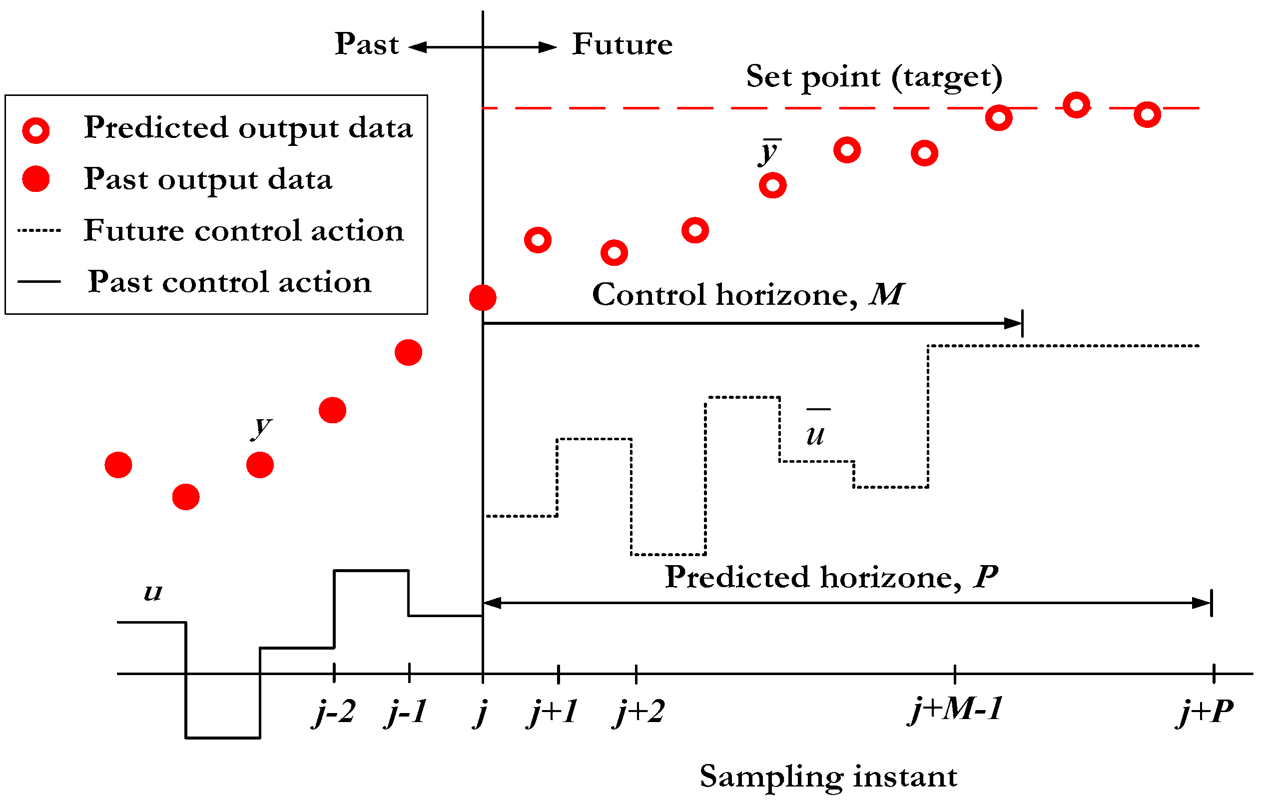
MPC for Virtual Inertia Control
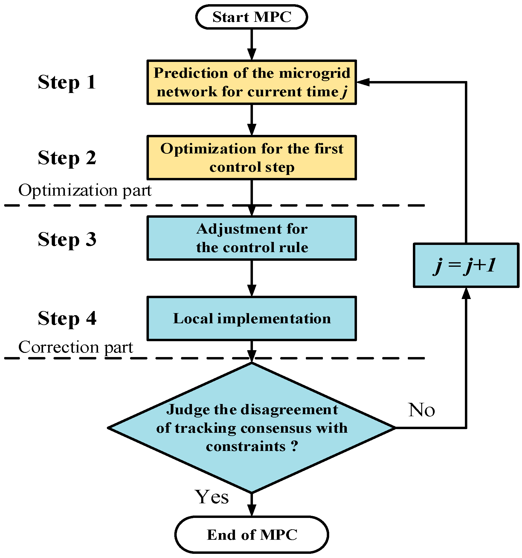
In this study, the MPC is implemented to produce the optimum control signal to the virtual inertia control system while respecting the given constraints over the output frequency deviation and the RES/load changes. The control loop of the virtual inertia system using MPC controller is shown in Figure 2. The objective function is to minimize the frequency deviation and also provide the robustness to the microgrid when a serious and continuous load/RES disturbances occur in a system with low overall inertia. The calculation of the virtual inertia control signal can be determined as:
Δ P i n e r t i a ( j + 1 ) = Δ P i n e r t i a ( j ) + A i = 0 n T δ i Δ u M P C ( j i )
Subject to:
Δ u M P C _ min Δ u M P C < Δ u M P C _ max
Δ f min Δ f < Δ f max
Δ P W _ min Δ P W < Δ P W _ max
Δ P i n e r t i a _ min Δ P i n e r t i a < Δ P i n e r t i a _ max
Figure 6 depicts the flowchart of the MPC designed for virtual inertia control. The corresponding steps are described as follows:
Step 1:
MPC agents monitor the corresponding information, and establish the virtual inertia model based MPC in form of Equation (13) over the current time j.
Step 2:
The optimization process for the first control step is performed using Equation (15).
Step 3:
The first control step ∆Pinertia(j) is extracted and implemented on the virtual inertia controller.
Step 4:
Determining whether the termination occurs depends on the disagreement of the tracking consensus within the constraints. If not, the optimization process is repeated for the next time j + 1.

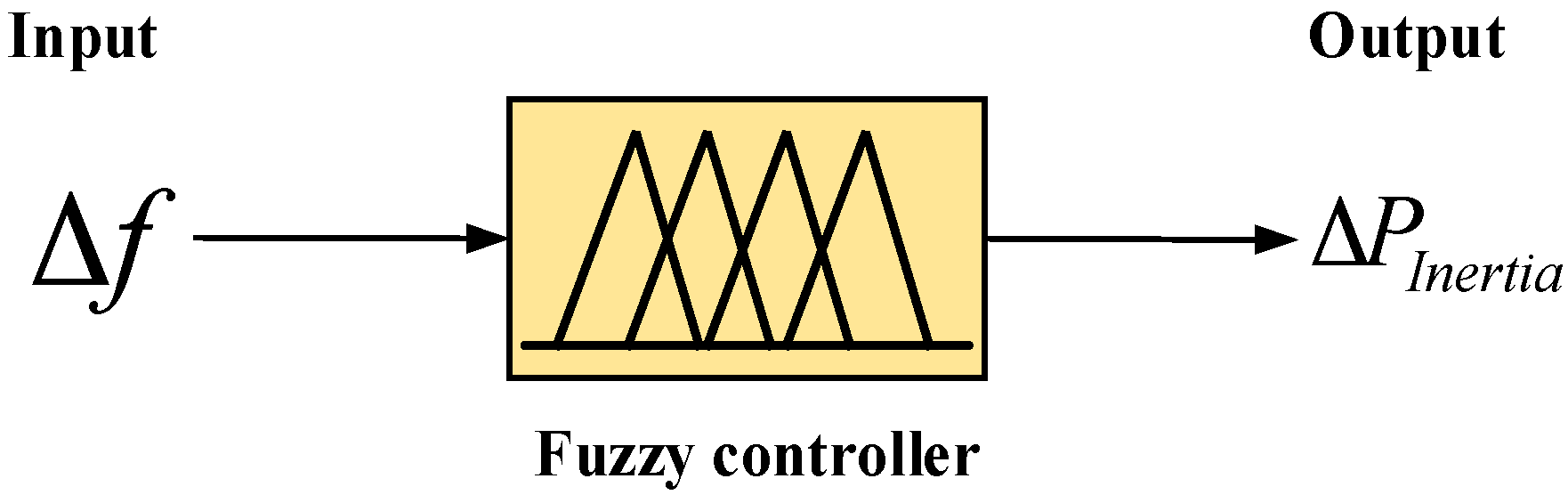
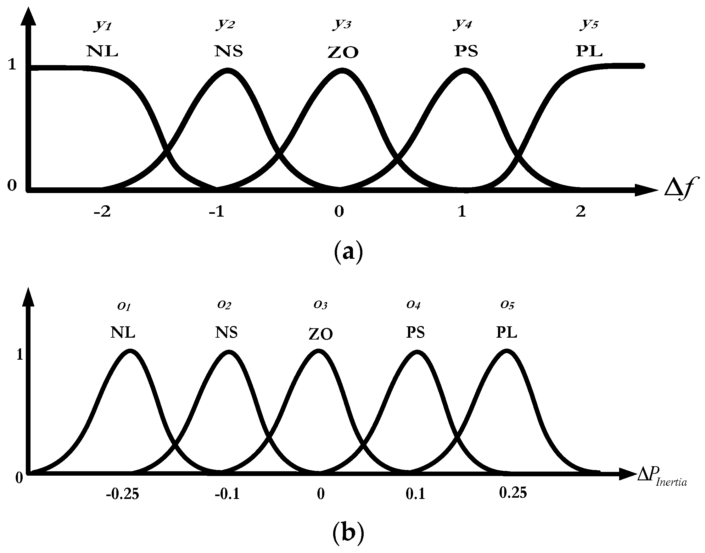
4. Fuzzy Logic System for Virtual Inertia Control (Comparative Method)

A fuzzy logic system is an intelligent adaptive controller, which is used in almost all fields of science and technology, including control of power system [38]. The fuzzy system is robust and suitable for practical applications and industries. It can approximate any smooth nonlinear function to any specified accuracy within any compact set. The fuzzy system tries to constitute the controller directly based on the measurements, long-term experiences, and the knowledge of domain experts. The fuzzy logic designs for frequency control are explained in [39,40,41,42].
In order to implement the fuzzy logic controller-based virtual inertia control for microgrid frequency stabilization, a set of fuzzy rules in Table 2 is used to map input variables (Δf) to output variables (ΔPinertia). The input variables are the rate of change of frequency (Δf) and the output variables are the virtual inertia power deviation (ΔPinertia). This controller aims to change the frequency deviation input signal to inertia power deviation for compensation of load/RES changes and various rates of microgrid rotation inertia as shown in Figure 7. In this study, the fuzzy system-based virtual inertia control is designed as a comparative intelligent controller to validate the effectiveness of the proposed virtual inertia controller-based MPC method.
The process of the proposed fuzzy system involves membership functions and if-then rules. This process is applied to calculate the mapping from the input values to the output values, consisting of three sub-processes (i.e., fuzzification, aggregation, and defuzzification). Five membership functions are defined for linguistic variables: Negative large (NL), Negative small (NS), Zero (ZO), Positive small (PS), and Positive large (PL). The membership functions are shown in Figure 8.
The virtual inertia control is described by a set of “if-then” based fuzzy rules. Using Table 2, fuzzy rules can be expressed in the form of if-then statement as Equation (20). The fuzzy rules can be shown as follow [42]:
If Input Δfi = yi, then Output ΔPinertia,i = oi

5. Simulation Results and Discussions

The simulation has been carried out in order to validate the effectiveness of the proposed control scheme. The MATLAB/Simulink® software has been applied for this simulation.
The parameters of the MPC controller are set as follows:
  • Prediction horizon = 15
  • Control horizon = 2
  • Weights on the manipulated variables = 0
  • Weights on the manipulated variable rates = 0.1
  • Weights on the output signals = 3
  • Sampling inertial = 0.01 s
The MPC constraints and the frequency deviation are considered as follows:
  • Maximum control action = 0.25 pu
  • Minimum control action = −0.25 pu
  • Maximum frequency deviation = 1 pu
  • Minimum frequency deviation = −1 pu
To investigate the microgrid frequency response and robustness with the proposed control method, four severe test scenarios are performed with the system parameters given in Table 1.

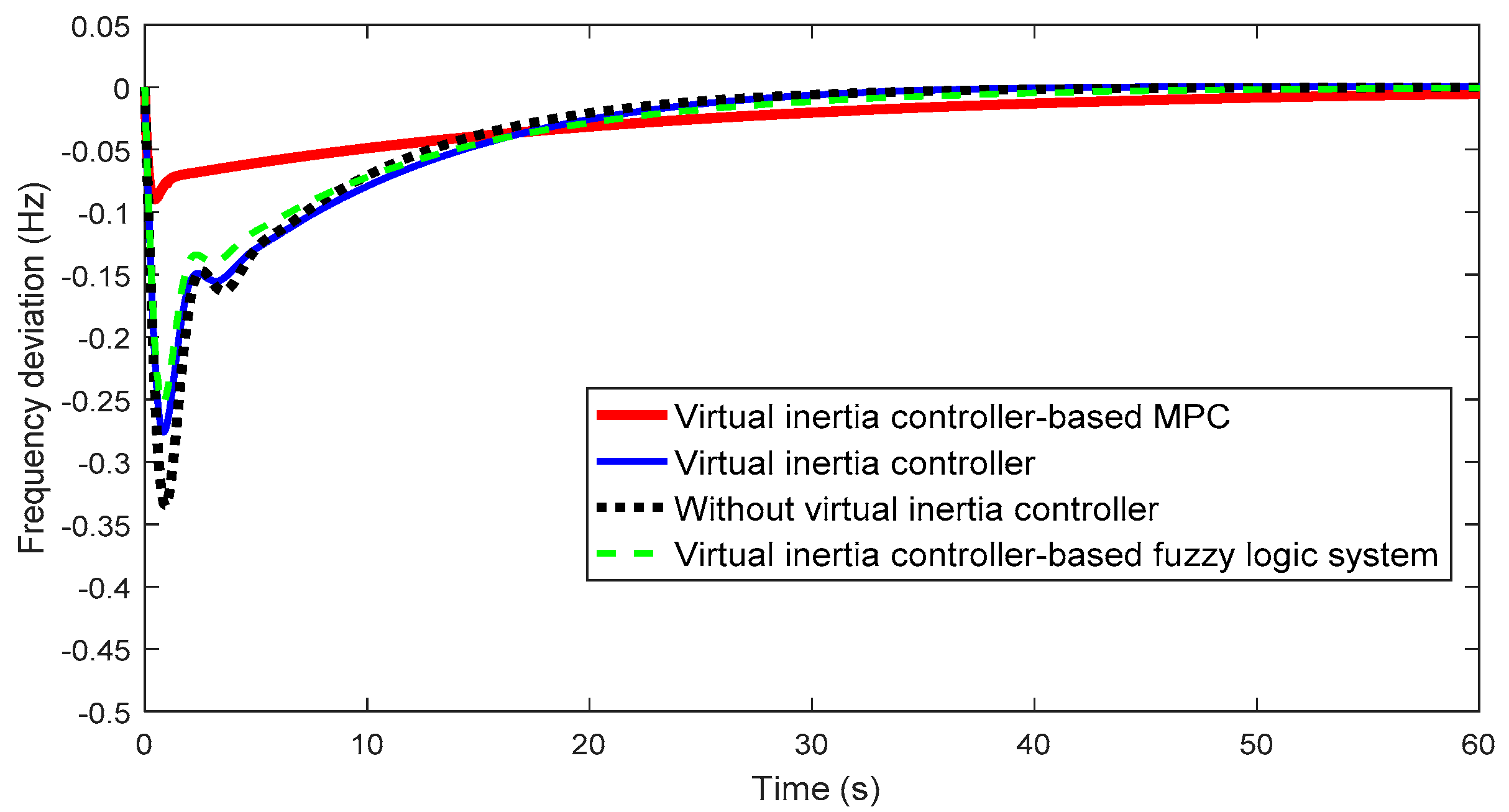
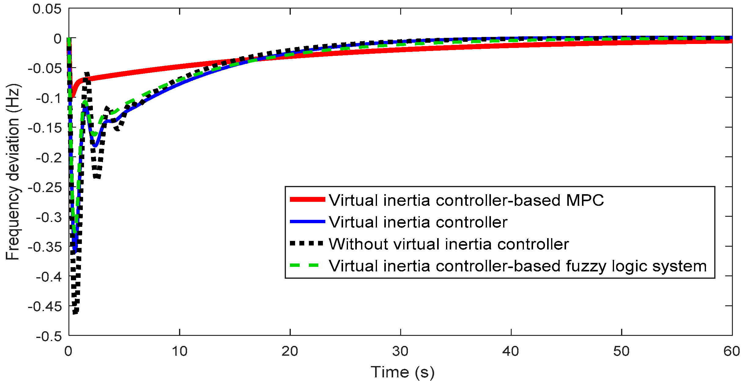
5.1. Scenario 1 (With Sudden Load Change)

In this scenario, the microgrid system shown in Figure 2 is considered as the test system to illustrate the effectiveness of the proposed control strategy. The wind power fluctuation has not been considered in this case. The proposed MPC control method is tested by implementing the step load disturbance (ΔPL = 0.1 pu) and the reduction of the system inertia by half of default value (TMG = 10). Figure 9 and Figure 10 show the simulation results for Scenario 1 under default system inertia and half of the default system inertia, respectively. It is obvious that the virtual inertia system (i.e., blue line) improves the frequency response and reduces transient excursions compared with the microgrid system without the virtual inertia control (i.e., black dotted line). The frequency performance is clearly improved by using the fuzzy system-based virtual inertia controller (i.e., green dotted line). The best frequency performance among all simulated control method is obtained by using MPC-based virtual inertia control (i.e., red line). In addition, the transient frequency performance is significantly improved when the microgrid utilizes MPC-based virtual inertia control.

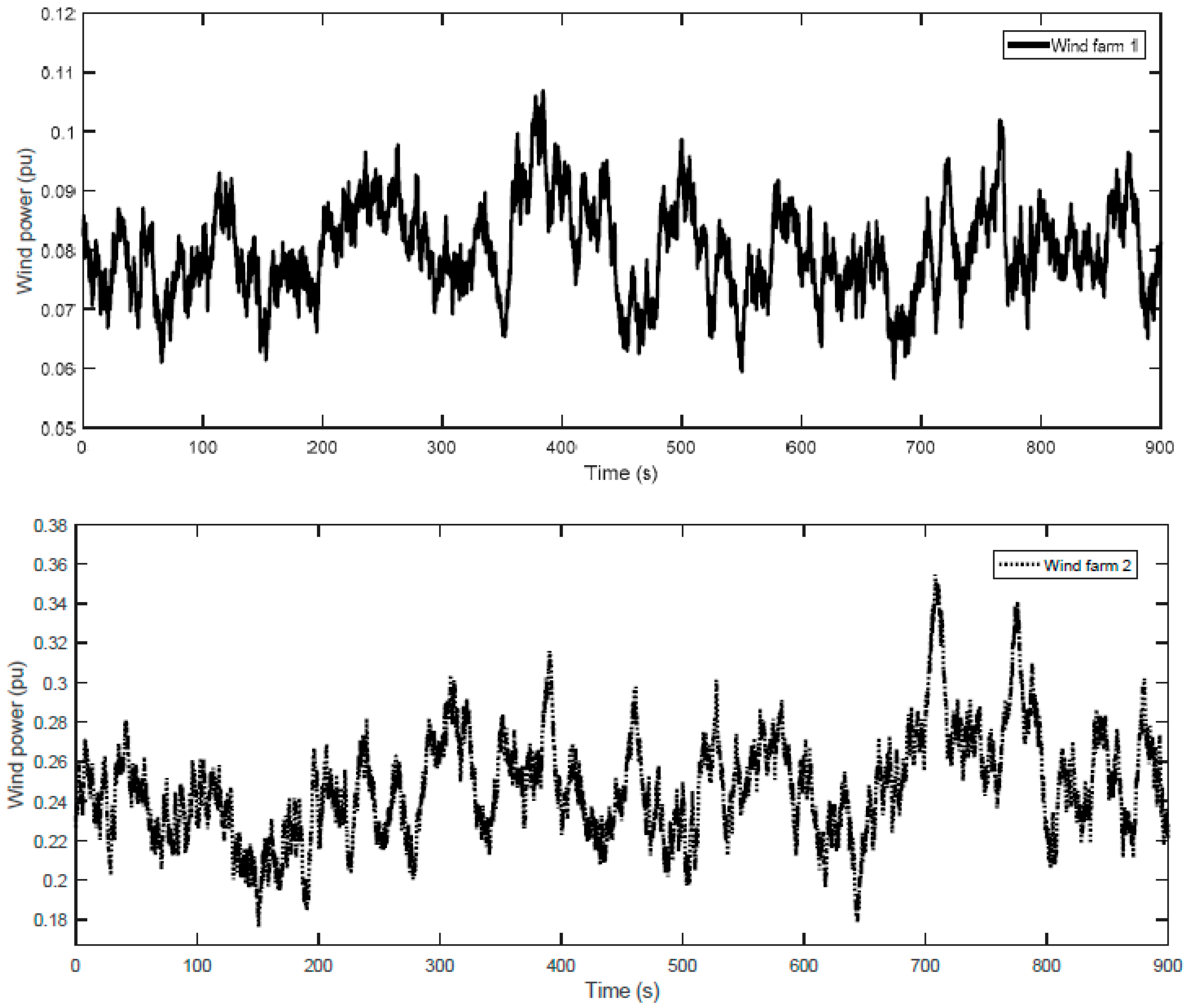
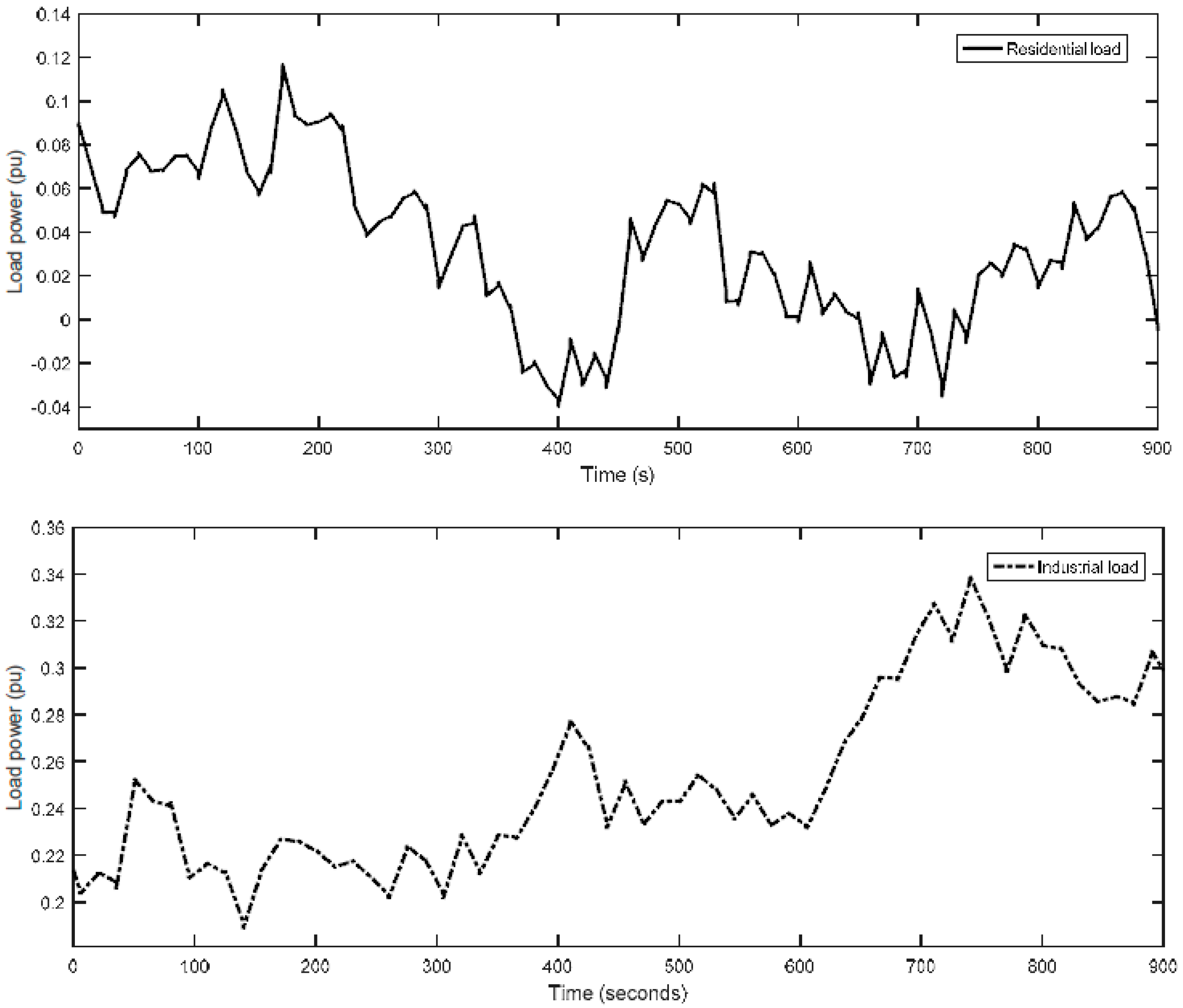
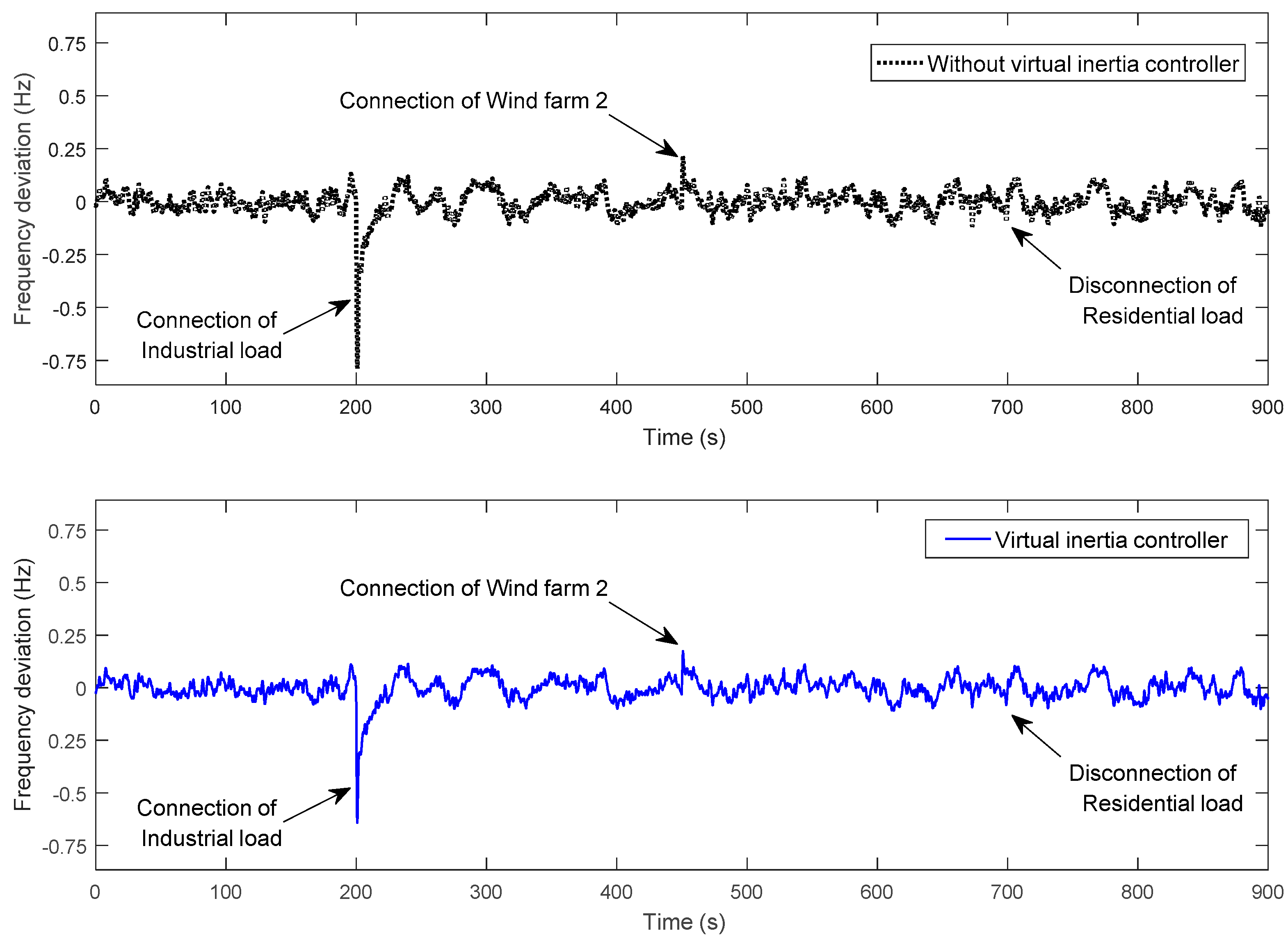
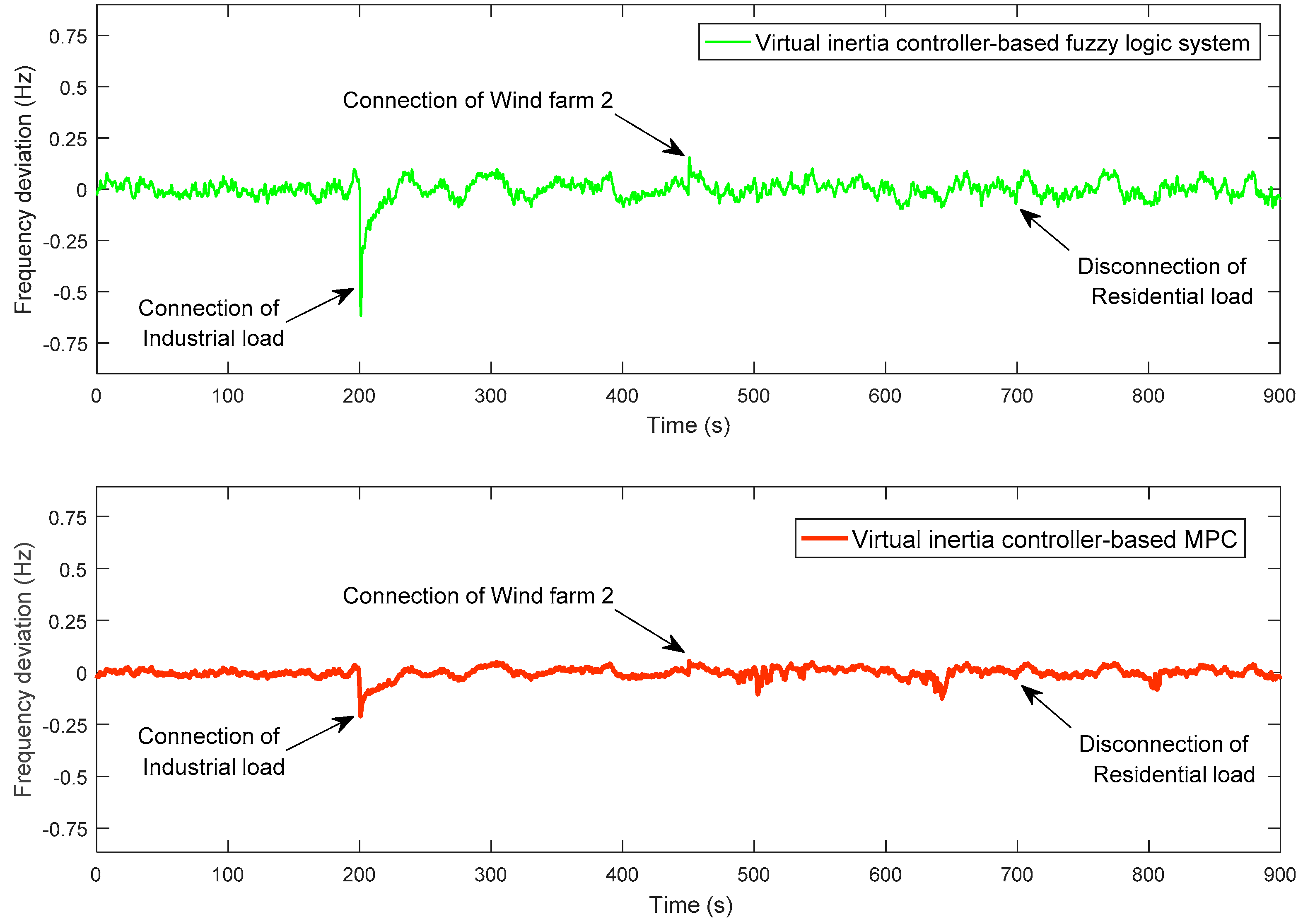
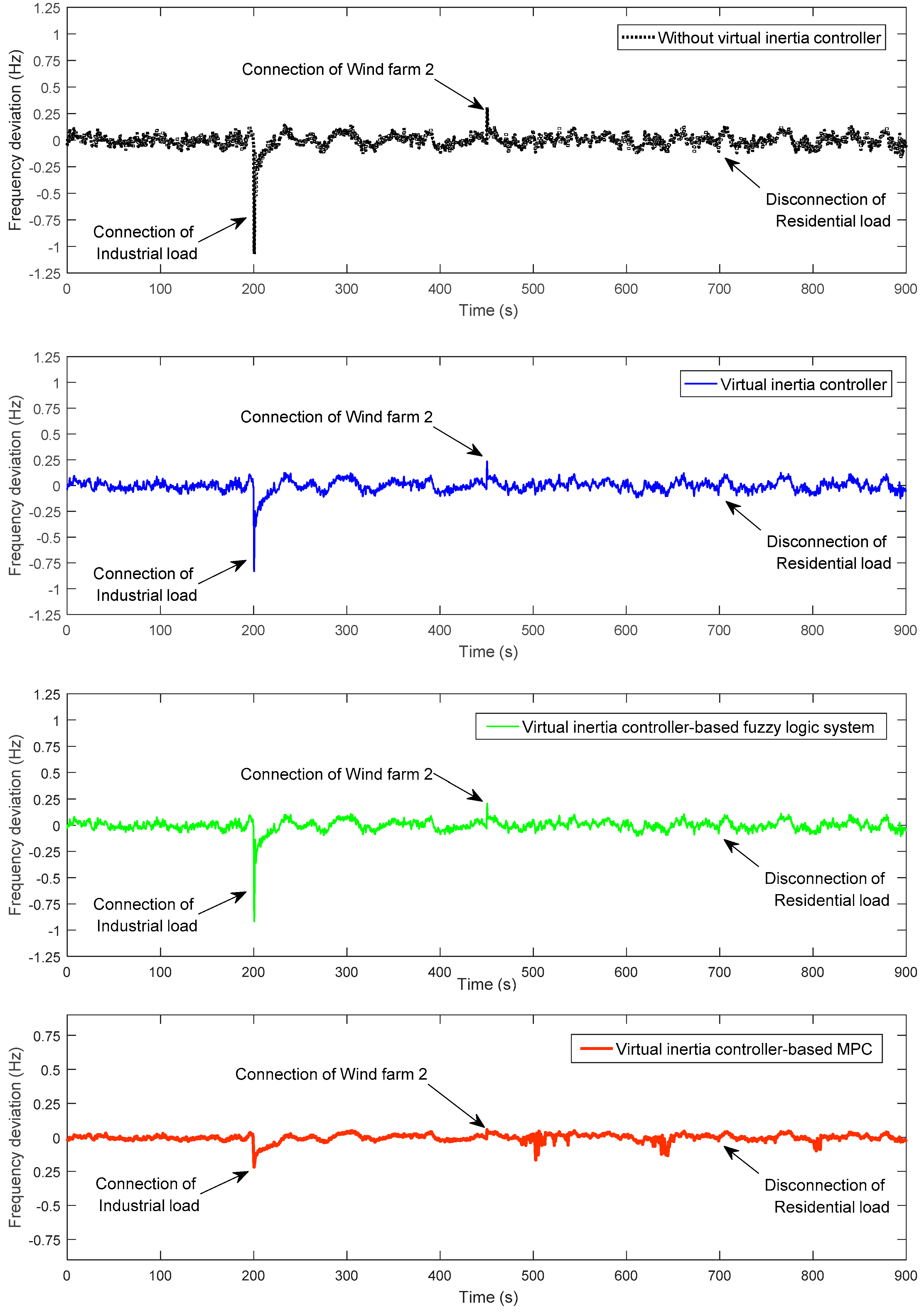
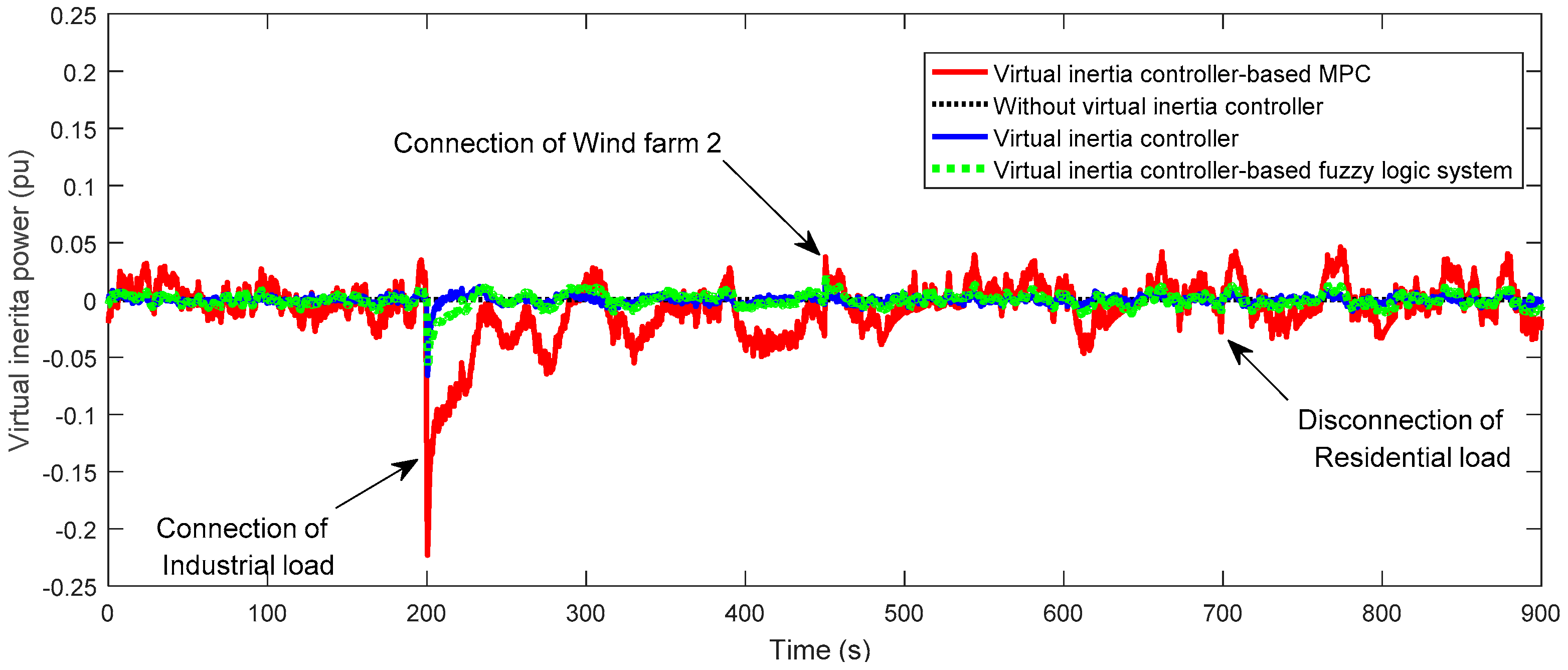
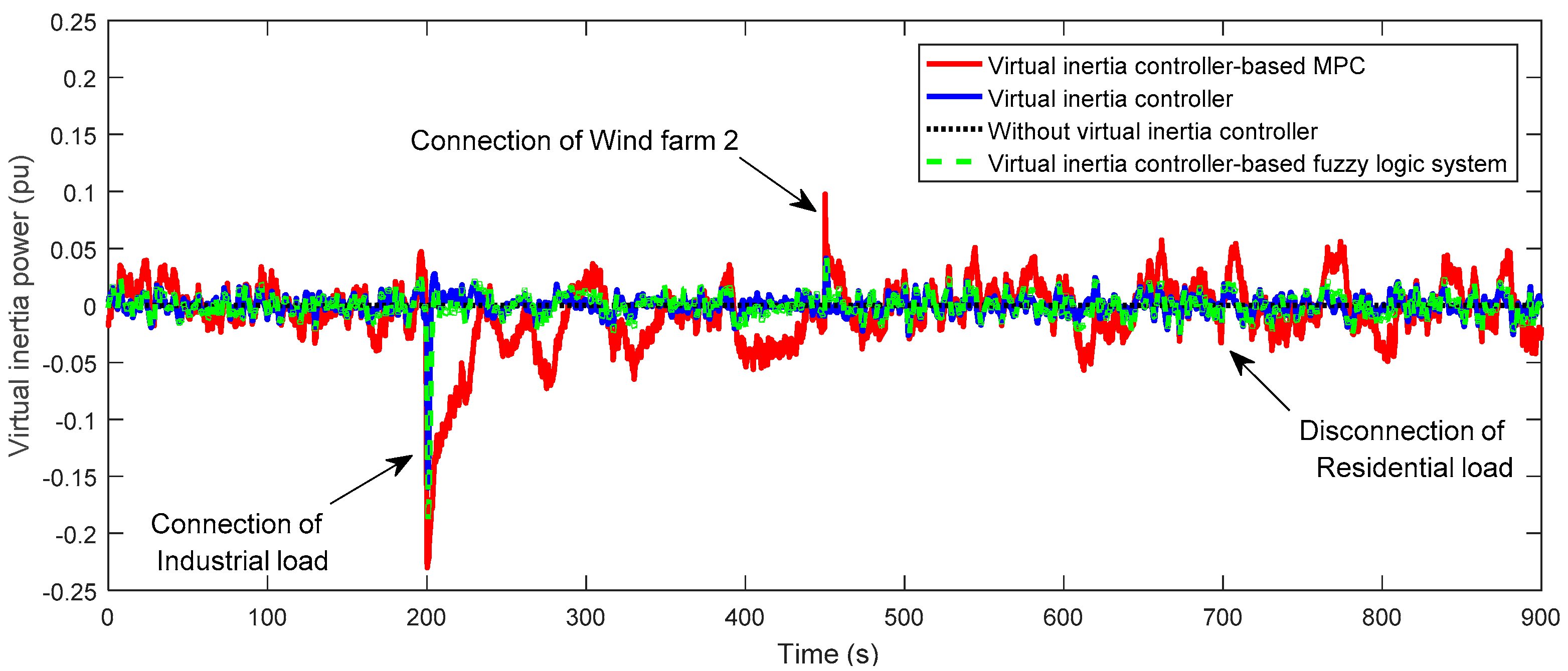
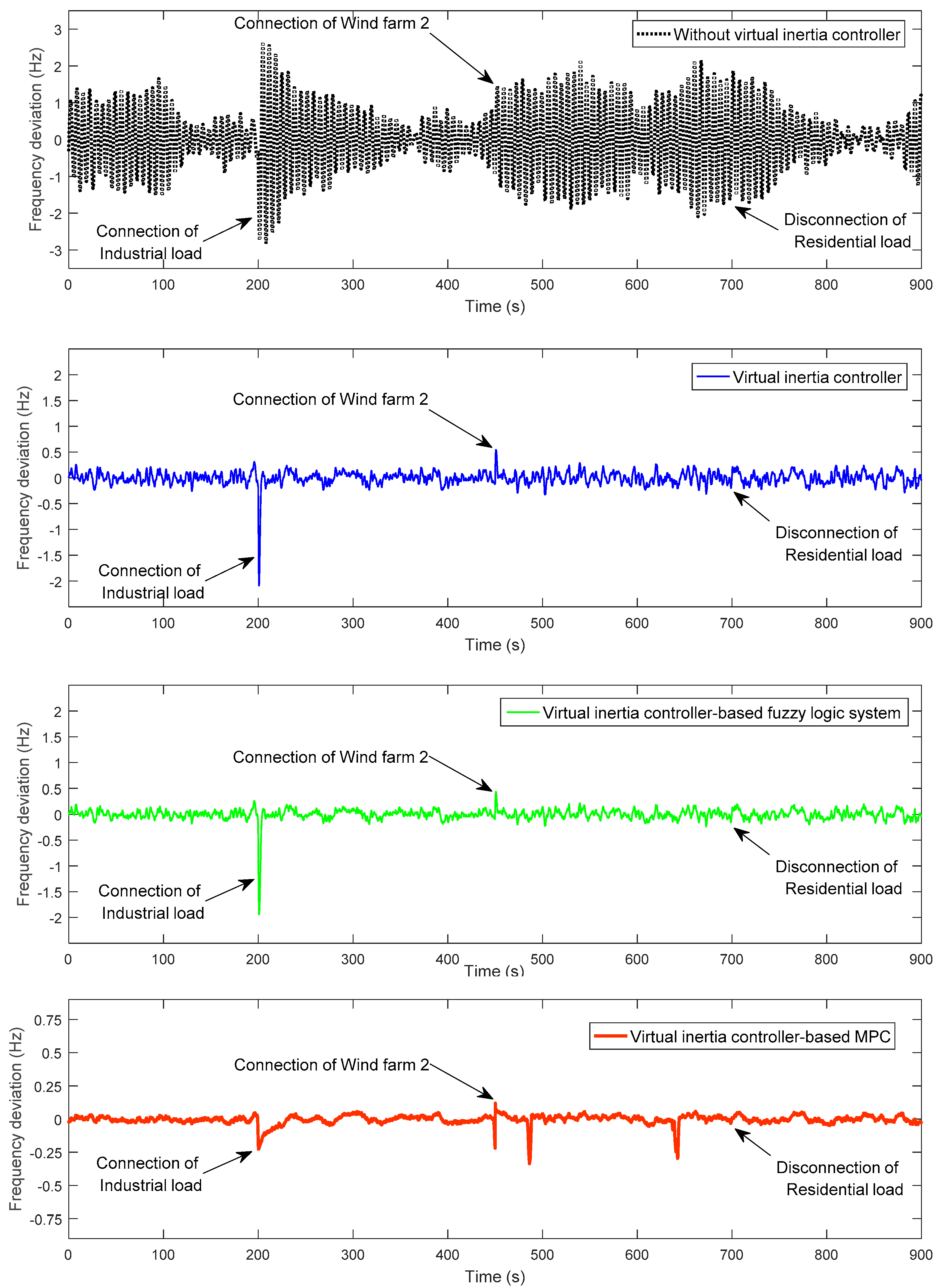
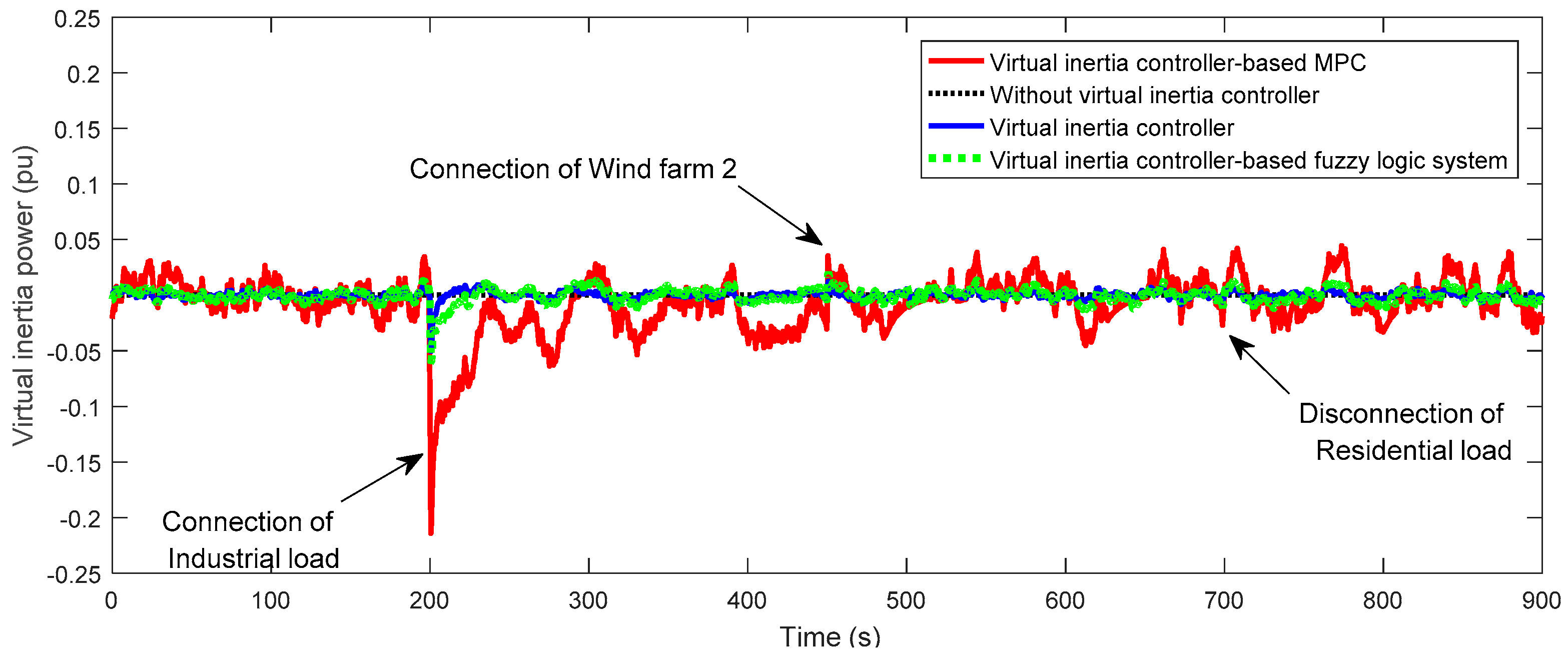
5.2. Scenario 2 (With High Integrations of Wind Energy and Load Disturbances)

In this section, the robustness of the proposed MPC control method is evaluated by implementing high fluctuation of wind power and load, which are divided into three sub-scenarios. The microgrid is tested in the presence of low fluctuated wind power (i.e., wind farm 1) and high fluctuated wind power (i.e., wind farm 2) shown in Figure 11, and also low random load change (i.e., residential load) and high random load change (i.e., industrial load) shown in Figure 12. For three sub-scenarios, wind farms and domestic loads are considered as the disturbances, which participate under the assumed multiple operating conditions in Table 3.
Scenario 2A: In this case, the microgrid system is assumed to have the default parameters with high system inertia (100% of default system inertia, TMG = 20) with multiple operating conditions in Table 3. Microgrid frequency response in this case is illustrated in Figure 13. From Figure 13, it is clearly seen that the frequency deviation of the microgrid with the proposed MPC-based virtual inertia control is less than ±0.25 Hz while the microgrid with the fuzzy logic and conventional virtual inertia controller give the frequency deviation of about ±0.6 Hz. Compared to the microgrid with fuzzy and conventional virtual inertia controllers, the MPC-based virtual inertia controller can provide smooth and secure frequency performance during the multiple operating conditions of the microgrid. Figure 14 shows that the virtual inertia power is greatly discharged by the proposed MPC-based controller (ΔPinertia ≈ 0.2 pu for the system with MPC-based virtual inertia controller, ΔPinertia ≈ 0.055 pu for the system with fuzzy controller and ΔPinertia ≈ 0.05 pu for the system with conventional virtual inertia controller). Thus, the frequency response of the microgrid is improved by using the MPC-based virtual inertia controller during the low and high fluctuation of wind power and load in a system with high penetration of RESs.
Scenario 2B: The microgrid system is assumed to have the default parameters and the microgrid is tested under the situation of half of default system inertia (50% of default system inertia, TMG = 10) with multiple operating conditions of load and wind variations as shown Table 3. The effect of medium system inertia through the proposed virtual inertia controller-based MPC is investigated. Figure 15 shows the frequency deviation of the four methods. It can be seen that the frequency is fluctuating more with high deviation in this scenario. In the case of no virtual inertia controller, the frequency deviation is about −1 Hz when the industrial load is connected to the microgrid at 200 s. In the case of the fuzzy and conventional virtual inertial controllers, the frequency deviation when the industrial load is connected to the microgrid at 200 s is about −0.75 Hz. The frequency in the case of the conventional virtual inertia controller is oscillating more than in the case of fuzzy logic system–based virtual inertia controller. It is clearly seen that the proposed MPC-based virtual inertia controller can maintain the frequency deviation within ±0.25 Hz during the connection of the industrial load. Figure 16 shows virtual inertia power produced by the four methods. Despite the situation of half of default system inertia, the virtual inertia power is greatly discharged by the proposed MPC-based controller. These results imply that the MPC-based virtual inertia controller is robust to compensate wind power and load variations under reduced system inertia condition.
Scenario 2C: The robustness of the proposed MPC-based virtual inertia controller is tested in the extreme scenario. Both the thermal generation governor and turbine time constants are increased to Tg = 0.19 s and Tt = 5.5 s (this can happen in case of off-line change of the practical turbine and governor, while the controller keeps the nominal values of these parts), which means the thermal generation unit is changed to unstable mode. The system inertia is changed from medium to low system inertia (TMG = 5). The microgrid is operated in several different operating conditions of load and wind power changes as shown in Table 3. Figure 17 shows that the virtual inertia power is greatly discharged by the proposed MPC-based controller under the severe condition of uncertainties. Figure 18 shows the frequency deviation of the four methods. In the case of no virtual inertia controller, the microgrid becomes unstable and frequency performance cannot hold against high fluctuation of wind power and loads. In the case of the fuzzy logic and conventional virtual inertia controllers, frequency is fluctuating more and yields large frequency transient compared with the proposed MPC-based controller. At this severe condition of uncertainties, the proposed MPC-based virtual inertia controller could maintain stable frequency response and yields small frequency transient compared with the other comparative methods. Hence, these results confirm that the MPC-based virtual inertia controller is very robust for frequency control in a system with high fluctuation of wind power and load under the critical situation of low system inertia.
Additionally, in order to investigate the effectiveness of the proposed MPC-based virtual inertia controller, the mean absolute frequency deviations when system inertia is set as high, medium, and low are carried out as shown in Table 4. When the system inertia decreases, the maximum frequency deviation of the microgrid is increased. However, the proposed MPC-based virtual inertia controller is able to maintain the frequency deviation better than the comparative methods.

6. Conclusions

In a system with high integration of RESs and continuous load disturbances, the virtual inertia system might not stable and cannot maintain and stabilize the frequency deviation within the desirable frequency performance, leading to instability and system collapse. In this paper, MPC is applied for the virtual inertia control for microgrid frequency stabilization during high integration of RES and fluctuating load disturbances. The proposed MPC-based virtual inertia control has been tested for several mismatched parameters of the microgrid, wind power, and load disturbances. Simulation results show that the proposed MPC-based virtual inertia control is robust against the parameter perturbation of the system and has desirable performance in comparison to fuzzy logic and conventional virtual inertia control designs in all of the performed test scenarios. It is concluded that the proposed MPC-based virtual inertia control is able to reduce and stabilize frequency deviation of the microgrid and gives robustness to the system subjected to uncertainties and disturbances over the fuzzy logic and conventional virtual inertia systems, thus significantly enhancing the stability and resiliency of the microgrid. Such a promising result provides a clear perspective on utilizing robust but simple methods for virtual inertia control. For further work, as the virtual inertia system is designed by utilizing the energy storage systems, the analysis of energy storage sizes and costs based on the existing technologies will be evaluated for optimum microgrid investments and operations.

Acknowledgments

This work was supported by the Mitani and Watanabe laboratory, department of electrical and electronics engineering, Kyushu Institute of Technology, Japan. The authors are grateful for the feedbacks of three anonymous reviewers and the editors of this journal; their comments helped us a lot in improving the quality of this paper.

Author Contributions

Thongchart Kerdphol proposed the MPC-based virtual inertia control and wrote the paper. Fathin S. Rahman provided theoretical knowledge for virtual inertia analysis. Komsan Hongesombut, Sinan Küfeoğlu and Yasunori Mitani provided theoretical knowledge in the energy and control domain and reviewed the paper.

Conflicts of Interest

The authors declare no conflict of interest.

Nomenclature

Vwthe wind speed (m/s)
dthe air density (kg/m3)
Athe cross section of the rotor for wind turbine (m2)
Cpthe power coefficient
Jthe moment of the system inertia (kg/m2)
ωthe rotor speed (rad/s)
Tm and Tethe mechanical and electrical torque, respectively
Pm and Pethe mechanical and electrical power, respectively
Sthe rated apparent power (VA)
y(j)the vector of manipulated movements at time instance j
u(j)the input at time instance j
nTthe number of impulse response coefficients applied to design the system
Athe interaction matrix
δithe coefficient number
r(j + h)the desired profile
Wy and Wuthe positive semidefinite weighting matrices
Zthe control horizon
Δ uMPC_minthe minimum of the change of control signal generated by the MPC
Δ uMPC_maxthe maximum of the change of control signal generated by the MPC
Δ fmin and Δfmaxthe minimum and maximum of the frequency deviation, respectively
Δ PW_minthe minimum of the change of the wind power penetration
Δ PW_maxthe maximum of the change of the wind power penetration
Δ Pinertia_minthe minimum of the change of the inertia power from the virtual inertia system
Δ Pinertia_maxthe maximum of the change of the inertia power from the virtual inertia system
Δ fithe rate of change of frequency at time instant i
Δ Pinertia,ithe virtual inertia power deviation at time instant i
yithe input membership function of Δ fi
oithe output membership function of Δ Pinertia,i

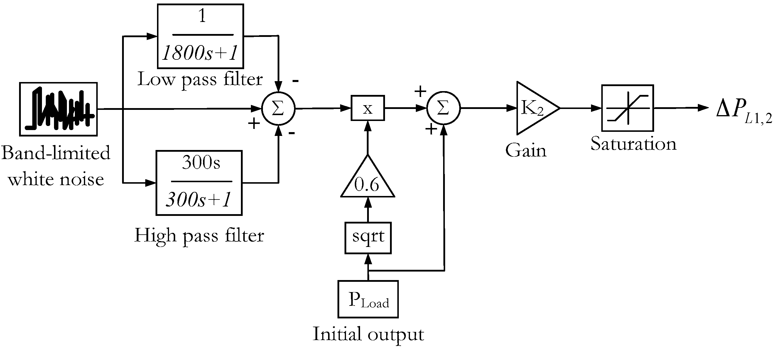
Appendix A. Load Model

In this study, the input power variability of the domestic load in the microgrid is evaluated by considering the deviation from the initial value as shown in Figure A1. The standard deviation is multiplied by the random output fluctuation delivered from the white noise block in MATLAB/Simulink® to generate the random power fluctuation on the domestic load profile in Figure 12. The load deviation is simulated close to an actual load change pattern by the following function [29,30]:
Δ P L 1 , 2 = 0.6 P L o a d
Figure A1. Domestic load model [29,30].
Sustainability 09 00773 g019

References

  1. Kerdphol, T.; Qudaih, Y.; Mitani, Y. Optimum battery energy storage system using PSO considering dynamic demand response for microgrids. Int. J. Electr. Power Energy Syst. 2016, 83, 58–66. [Google Scholar] [CrossRef]
  2. Marzband, M.; Ghazimirsaeid, S.S.; Uppal, H.; Fernando, T. A real time evalution of energy management systems for smart hybrid home microgrids. Electr. Power Syst. Res. 2017, 143, 624–633. [Google Scholar] [CrossRef]
  3. Marzband, M.; Ardeshiri, R.; Moafi, M.; Uppal, H. Distributed generation for economic benefit maximization through coalition formation based game theory concept. Int. Trans. Electr. Energy Syst. 2017. [CrossRef]
  4. Yao, G.; Zhang, Z.; Tang, T.; Benbouzid, M. Small signal models based stability and controller parameters sensitivity analysis of microgrid in islanded mode. In Proceedings of the 40th Annual Conference of the IEEE Industrial Electronics Society, Dallas, TX, USA, 29 October–1 November 2014; pp. 4995–5001. [Google Scholar]
  5. Bevrani, H.; Watanabe, M.; Mitani, Y. Power System Monitoring and Control; John Wiley & Sons: Hoboken, NJ, USA, 2014; Chapter 9. [Google Scholar]
  6. Li, C.; Xu, J.; Zhao, C. A coherency-based equivalence method for MMC inverters using virtual synchronous generator control. IEEE Trans. Power Electron. 2012, 31, 1–6. [Google Scholar] [CrossRef]
  7. Liu, J.; Miura, Y.; Ise, T. Comparison of dynamic characteristics between virtual synchronous generator and droop control in inverter-based distributed generators. IEEE Trans. Power Electron. 2015, 31, 3600–3611. [Google Scholar] [CrossRef]
  8. Chen, Y.; Hesse, R.; Turschner, D.; Beck, H.P. Investigation of the virtual synchronous machine in the islanded mode. In Proceedings of the IEEE Transactions on Power Delivery, Berlin, Germany, 14–17 October 2012; pp. 1369–1378. [Google Scholar]
  9. Beck, H.P.; Hesse, R. Virtual synchronous machine. In Proceedings of the 9th International Conference on Power Quality and Utilizations, Barcelona, Spain, 9–11 October 2007; pp. 1–6. [Google Scholar]
  10. Karapanos, V.; Haan, S.; Zwetsloot, K. Real time simulation of a power system with VSG hardware in the loop. In Proceedings of the 37th Annual conference on IEEE Industrial Electronics Society, Melbourne, Australia, 7–10 November 2011; pp. 3748–3754. [Google Scholar]
  11. Zhong, Q.C.; Weiss, G. Synchonverter: Inverters that mimic synchronous generators. IEEE Trans. Ind. Electron. 2011, 58, 1259–1265. [Google Scholar] [CrossRef]
  12. Cam, E.; Kocaarslan, I. Load frequency control in two area power systems using fuzzy logic controller. Energy Convers. Manag. 2005, 46, 233–243. [Google Scholar] [CrossRef]
  13. Birch, A.P.; Sapeluk, A.T.; Ozveren, C.S. An enhanced neural network load frequency control technique. In Proceedings of the International Conference on Control (Control ’94), Coventry, UK, 21–24 March 1994; p. 389. [Google Scholar]
  14. Farhangi, R.; Boroushaki, M.; Hosseini, H. Load-frequency control of interconnected power system suing emotional learning-based intelligent controller. Electr. Power Energy Syst. 2012, 36, 76–83. [Google Scholar]
  15. Kerdphol, T.; Qudaih, Y.; Watanabe, Y.; Mitani, Y. RBF neural network-based online intelligent management of a battery energy storage system for stand-alone microgrids. Energy Sustain. Soc. 2016, 6, 1–16. [Google Scholar] [CrossRef]
  16. Mayer, B.; Killian, M.; Kozek, M. Hierarchical model predictive control for sustainable building automation. Sustainability 2017, 9, 1–20. [Google Scholar] [CrossRef]
  17. Kong, X.B.; Lui, X.J.; Lee, K.Y. An effective nonlinear multiple variable HMPC for USC Power Plant incorporating NFN-based Modelling. IEEE Trans. Ind. Inform. 2016, 12, 555–566. [Google Scholar] [CrossRef]
  18. Kong, X.B.; Liu, X.J.; Lee, K.Y. Nonlinear multivariable hierarchical model predictive control for boiler-turbine system. Energy 2016, 93, 309–322. [Google Scholar] [CrossRef]
  19. Liu, X.J.; Jiang, D.; Lee, K.Y. Quasi-min-max-fuzzy MPC of UTSG water level based on off-line invariant set. IEEE Trans. Nucl. Sci. 2015, 62, 2266–2272. [Google Scholar] [CrossRef]
  20. Hu, K.; Yuan, J.Q. Multi-model predictive control method for nuclear steam generator water level. Energy Convers. Manag. 2008, 49, 1167–1174. [Google Scholar] [CrossRef]
  21. Mohamed, T.H.; Bevrani, H.; Hassan, A.A.; Hiyama, T. Decentralized model predictive based load frequency control in an interconnected power system. Energy Convers. Manag. 2011, 52, 1208–1214. [Google Scholar] [CrossRef]
  22. Mohamed, T.H.; Morel, J.; Bevrani, H.; Hiyama, T. Model predictive based load frequency control design concerning wind turbines. Int. J. Electr. Power Energy Syst. 2012, 43, 859–867. [Google Scholar] [CrossRef]
  23. Pahasa, J.; Ngamroo, I. Coordinated control of wind turbine blade pitch angle and PHEVs using MPCs for load frequency control of microgrid. IEEE Syst. J. 2016, 10, 97–105. [Google Scholar] [CrossRef]
  24. Pahasa, J.; Ngamroo, I. PHEVs bidirectional charging/discharging and SOC control for microgrid frequency stabilization using multiple MPC. IEEE Trans. Smart Grid 2015, 6, 526–533. [Google Scholar] [CrossRef]
  25. Senjyu, T.; Tokudome, M.; Yona, A.; Funabashi, T. A frequency control approach by decentralized controllable loads in small power systems. IEEJ Trans. Power Energy 2009, 129, 1074–1080. [Google Scholar] [CrossRef]
  26. Mentesidi, K.; Garde, R.; Aquado, M.; Rikos, E. Implementation of a fuzzy logic controller for virtual inertia emulation. In Proceedings of the IEEE International Symposium on Smart Electric Distribution System and Technologies, Vienna, Austria, 8–11 September 2015; pp. 1–6. [Google Scholar]
  27. Inoue, T.; Amano, H. A thermal power plant model for dynamic simulation of load frequency control. In Proceedings of the IEEE PES Power Systems Conference Exposition, Atlanta, GA, USA, 29 October–1 November 2006; pp. 1442–1447. [Google Scholar]
  28. Kundur, P. Power System Stability and Control; McGraw Hill: New York, NY, USA, 1993. [Google Scholar]
  29. Li, X.; Hui, D.; Lai, X.; Yan, T. Power quality control in wind/fuel cell/battery/hydrogen electrolyser hybrid microgrid power system. Appl. Exp. Qual. Control Conf. 2011, 1, 579–594. [Google Scholar]
  30. Michigami, T.; Ishii, T. Construction of fluctuation load model and dynamic simulation with LFC control of DC power system and frequency converter interconnection. In Proceedings of the IEEE PES Transmission Distribution Conference Exhibition, Yokohama, Japan, 6–10 October 2002; pp. 382–387. [Google Scholar]
  31. Licari, J.; Ekanayake, J.; Moore, I. Inertia response from full-power converter-based permanent magnet wind generator. J. Mod. Power Syst. Clean Energy 2013, 1, 26–33. [Google Scholar] [CrossRef]
  32. Weedy, B.M.; Cory, B.J.; Jenkins, N.; Ekanayake, J.B.; Strbac, G. Electric Power System, 5th ed.; John Wiley & Sons: London, UK, 2012. [Google Scholar]
  33. Bevrani, H. Robust Power System Frequency Control; Springer: Cham, Switzerland, 2014. [Google Scholar]
  34. Kufeoglu, S.; Lehtonen, M. A review on the theory of electric power reliability worth and customer interruption costs assessment techniques. In Proceedings of the International Conference on the European Energy Market (EEM), Porto, Portugal, 6–9 June 2016; pp. 6–9. [Google Scholar]
  35. Bemporad, A.; Morari, M.; Ricker, N.L. Model Predictive Control Toolbox User’s Guide; Mathworks Inc.: Natick, MA, USA, 2013. [Google Scholar]
  36. Pisaturo, M.; Cirrincione, M.; Senatore, A. Multiple constrained MPC design for automotive dry clutch engagement. IEEE Trans. Mechatron. 2014, 20, 469–480. [Google Scholar] [CrossRef]
  37. Vanantwerp, J.G.; Braatz, R.D. Fast model predictive control of sheet and film processes. IEEE Trans. Control Syst. 2005, 8, 408–417. [Google Scholar] [CrossRef]
  38. Bevrani, H.; Hiyama, T. Intelligent Automatic Generation Control; CRC Press: Boca Raton, FL, USA, 2011. [Google Scholar]
  39. Chown, G.A.; Hartman, R.C. Design and experience with a fuzzy logic controller for automatic generation control (AGC). IEEE Trans. Power Syst. 1998, 13, 965–970. [Google Scholar] [CrossRef]
  40. Feliachi, A.; Rerkpreedapong, D. NERC compliant load frequency control design using fuzzy rules. Electr. Power Syst. Res. 2005, 73, 101–106. [Google Scholar] [CrossRef]
  41. Rao, C.S.; Nagaraju, S.S.; Raju, P.S. Automatic generation control of TCPS based hydrothermal system under open market scenario: A fuzzy logic approach. Electr. Power Syst. Res. 2009, 31, 315–322. [Google Scholar] [CrossRef]
  42. Bevrani, H.; Daneshmand, P.R. Fuzzy logic-based load frequency control concerning high penetration of wind turbines. IEEE Syst. J. 2012, 6, 173–180. [Google Scholar] [CrossRef]
Figure 1. The studied microgrid system.
Sustainability 09 00773 g001
Figure 2. The non-linear model of the studied microgrid.
Sustainability 09 00773 g002
Figure 3. The model of wind turbine generation.
Sustainability 09 00773 g003
Figure 4. The virtual inertia power control using the model predictive control (MPC).
Sustainability 09 00773 g004
Figure 5. The general concept of MPC.
Sustainability 09 00773 g005
Figure 6. The flowchart of MPC for virtual inertia control.
Sustainability 09 00773 g006
Figure 7. The framework of virtual inertial control using the fuzzy logic design.
Sustainability 09 00773 g007
Figure 8. Symmetric fuzzy membership functions: (a) Input pattern; (b) Output pattern.
Sustainability 09 00773 g008
Figure 9. Frequency deviation of the microgrid during the sudden load change and default system inertia (TMG = 20).
Sustainability 09 00773 g009
Figure 10. Frequency deviation of the microgrid during the sudden load change and reduction of half of default system inertia (TMG = 10).
Sustainability 09 00773 g010
Figure 11. The wind power fluctuations of case studies in Scenario 2.
Sustainability 09 00773 g011
Figure 12. The random load deviations of case studies in Scenario 2.
Sustainability 09 00773 g012
Figure 13. Frequency deviation of scenario 2A (i.e., high system inertia).
Sustainability 09 00773 g013aSustainability 09 00773 g013b
Figure 14. Virtual inertia power of scenario 2A.
Sustainability 09 00773 g014
Figure 15. Frequency deviation of scenario 2B (i.e., medium system inertia).
Sustainability 09 00773 g015
Figure 16. Virtual inertia power of scenario 2B.
Sustainability 09 00773 g016
Figure 17. Virtual inertia power of scenario 2C.
Sustainability 09 00773 g017
Figure 18. Frequency deviation of scenario 2C (i.e., mismatched parameters of main thermal generation and low system inertia).
Sustainability 09 00773 g018
Table 1. Microgrid system parameters.
ParametersValue
Frequency bias factor, Bi (puMW/Hz)1
Integral control variable gain, Ki0.05
Governor time constant, Tg (s)0.1
Turbine time constant, Tt (s)0.4
Droop constant, R (Hz/puMW)2.4
Microgrid system gain, KMG (Hz/puMW)120
Microgrid time constant, TMG (s)20
Virtual inertia variable gain, KVI0.08
Virtual inertia time constant, TVI (s)10
Maximum limit of valve gate, VU0.1
Minimum limit of valve gate, VL−0.1
Table 2. Fuzzy rule base for virtual inertia control.
Input (Δfi)NLNSZOPSPL
Output (ΔPinertia,i)PLPSZONSNL
Table 3. Multiple operating conditions of the studied microgrid.
Disturbance SourceStarting Time (s)Stopping Time (s)Size (MW)
Wind farm 1initial-2.1
Wind farm 2450 s-7.0
Residential loadinitial700 s2.2
Industrial load200 s-6.8
Table 4. Evaluation indices of frequency fluctuation.
ScenarioSystem InertiaMean Absolute Frequency Deviation (Hz)
No Virtual Inertia ControllerVirtual Inertia ControllerVirtual Inertia Controller-Based FuzzyVirtual Inertia Controller-Based MPC
2AHigh (100%)0.047640.044960.042180.02176
2BMedium (50%)0.051070.046800.044010.02193
2CLow (25%)0.736580.094330.093040.02540

