
New Configuration and Novel Reclosing Procedure of Distribution System for Utilization of BESS as UPS in Smart Grid

Yonam Institute of Technology, Jinju 52821, Korea
Sustainability 2017, 9(4), 507; https://doi.org/10.3390/su9040507
Submission received: 13 January 2017
/
Revised: 6 March 2017
/
Accepted: 21 March 2017
/
Published: 27 March 2017
(This article belongs to the Special Issue Smart Grid)
Abstract
:This paper proposes a new configuration and novel reclosing procedure of a distribution system with a battery energy storage system (BESS) used as an uninterruptible power supply (UPS) in a smart grid. The proposed new configurations of the distribution systems are the installation of a circuit breaker (CB) on both sides of the distribution line, the replacement of the recloser with a CB and protective relay, and the requirement of a communication method. The proposed reclosing procedure performs the reclosing of the CB at the load side and then judges the fault clearance using the load current. If the fault is cleared, the synchronism checking between the main source and the BESS is performed. After completing this, the CB at the main source side is reclosed. The smart grid environment, including a new distribution system, BESS, and reclosing method are modeled with the Electromagnetic Transients Program (EMTP)/ATPDraw. To verify the proposed method, the various simulations according to the fault clearance time are performed and analyzed. The simulation results show that the BESS can be operated as a UPS and successful reclosing is possible.
1. Introduction
For the establishment of a smart grid, a field test and related research on the connection of a battery energy storage system (BESS) to the distribution system have been carried out. The field test of the BESS for frequency regulation has been carried out at the Jochon Substation in Jeju, Korea. In addition, various studies have been performed. In [1,2,3,4,5], the control strategies for the output smoothing through linkage of the BESS and renewable energy were discussed. In [6,7,8,9], the energy management strategy using a BESS were discussed. In [10,11], the applications of a BESS for demand response were discussed. In [12,13,14] the control strategy for frequency regulation and peak load shaving using a BESS was discussed. In [15,16], the applications of a BESS as an uninterruptible power supply (UPS) were discussed. As more and more BESSs for smart grids will be adopted in power distribution networks, utilities will have to adapt/change their practices/procedures with respect to the interconnection of BESSs. However, the previous references do not explore this issue. This paper focuses on the reclosing study among various practices/procedures.
The BESS can be used for various purposes, such as frequency regulation, peak load shaving, and UPS. To use the BESS for frequency regulation and peak load shaving, a distribution system must be operated at a steady state. The new challenge and countermeasure in the reclosing of the distribution system with a BESS used for these purposes were discussed in [17]. A BESS can feature the function of a UPS to maintain electrical load power in the event of the power interruption or to provide protection from a power surge [16]. A UPS is an electrical apparatus that provides emergency power to a load when the input power source or main power fails. A UPS differs from an auxiliary or emergency power system or standby generator in that it will provide near-instantaneous protection from input power interruptions by supplying energy stored in batteries. If the BESS is used as a UPS, it is connected to the distribution system during a fault and maintains the power supply to a healthy phase. In [17], the BESS is operated at a steady state and, hence, it is disconnected from the distribution system. Therefore, this method cannot apply to the operation of a BESS as a UPS. This is a limitation of configuration in [17]. In [18], the reclosing method considering the BESS as a UPS were discussed, however, this method can be only applied to the single phase loads. In other words, a limitation of [18] is that it is impossible to apply this method to the three phase loads. To overcome these limitations, this paper proposes a new configuration and reclosing method.
A recloser in electric power distribution is a circuit-interrupting device equipped with a mechanism that can automatically close the breaker after it has been opened due to a fault. A circuit breaker (CB) is an automatically-operated electrical switch designed to protect an electrical circuit from damage caused by excess current, typically resulting from an overload or short circuit. This device cannot be automatically closed. A protective relay in electrical engineering is a relay device designed to trip a circuit breaker. This device can be designed to have multiple functions.
If the BESS is connected to the power grid as a UPS, the distribution system experiences a new challenge in reclosing because the BESS will not be disconnected from the distribution system even under fault conditions and will maintain the power supply to a healthy phase. The conventional reclosing scheme does not consider the synchronism problem between the utility and the BESS when reclosing is attempted. Due to existence of both sources at the sending and receiving ends, a reclosing in the distribution system with a BESS is very similar to reclosing in a transmission line and, thus, the synchronism problem including voltage, phase angle, and frequency must be considered [18]. This problem cannot be solved in the conventional recloser because it performs the closing operation of the recloser only after the fixed dead time. To solve this problem, the protective relay, having multiple functions, and a CB are required. Therefore, the new configuration and reclosing procedure are required for utilization of a BESS as a UPS in a smart grid.
In this paper, the new configuration and novel reclosing procedure of the distribution system considering the BESS for a smart grid are proposed. This paper focuses the operation of the BESS as a UPS. In the proposed configuration, a CB is additionally installed on the load side in the power distribution system. When a fault occurs, both CBs at the main source and load side are opened at the same time. After a fixed dead time, the reclosing operation of the CB at the load side is firstly performed, and then the fault clearance is judged using the load current. If the fault is cleared, the CB at the main source side is reclosed after synchronism checking between the main power source and the power from the BESS. To verify the proposed method, the BESS, distribution system, and proposed reclosing method are modeled using Electromagnetic Transients Program (EMTP)/ATPDraw. The various simulations according to the fault clearance time are performed and the results are analyzed. From the simulation results, the reclosing can be successfully performed by the proposed configuration of the distribution system and the reclosing procedure, and the BESS can be operated as a UPS.
2. Conventional Configuration and Reclosing Procedure of Distribution System
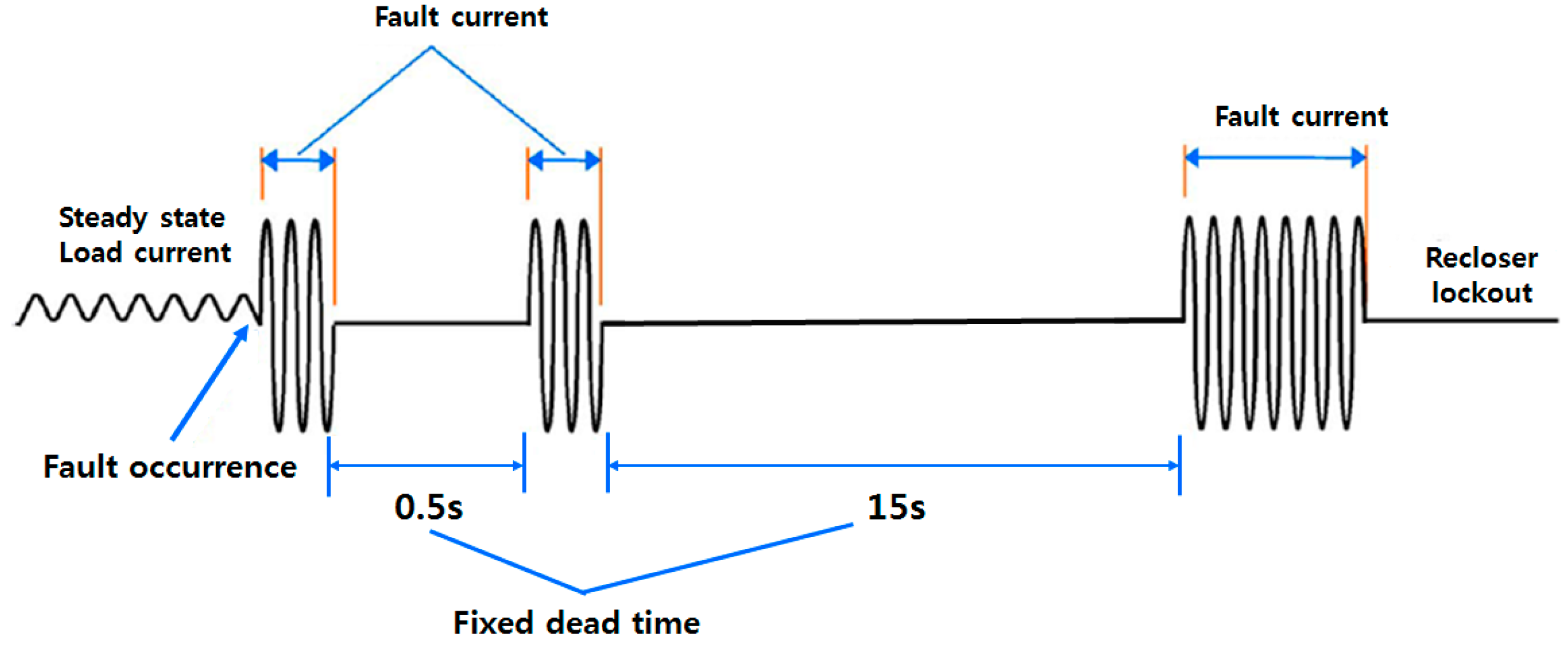
Figure 1 shows the conventional configuration of the distribution system. A recloser is only installed at the main source side of the distribution line. The recloser is a circuit-interrupting device for distribution systems in which the magnitudes of the fault currents are limited. Specifically, the operation sequence of a recloser in a conventional distribution system of the Korea Electric Power Corporation has fixed dead times of 0.5 s and 15 s as shown in Figure 2 [19]. The recloser is opened if the current increases due to fault occurrence. After elapsing the fixed dead time of 0.5 s, the first reclosing is attempted. If the fault is not cleared, the recloser is re-opened again because of large fault current. Then, the second reclosing is attempted after 15 s. Before the successful reclosing is performed, the Load 2 in Figure 1 experiences the outage.
3. New Configuration of the Distribution System and a Novel Reclosing Procedure Considering a BESS
3.1. New Configuration of Distribution System
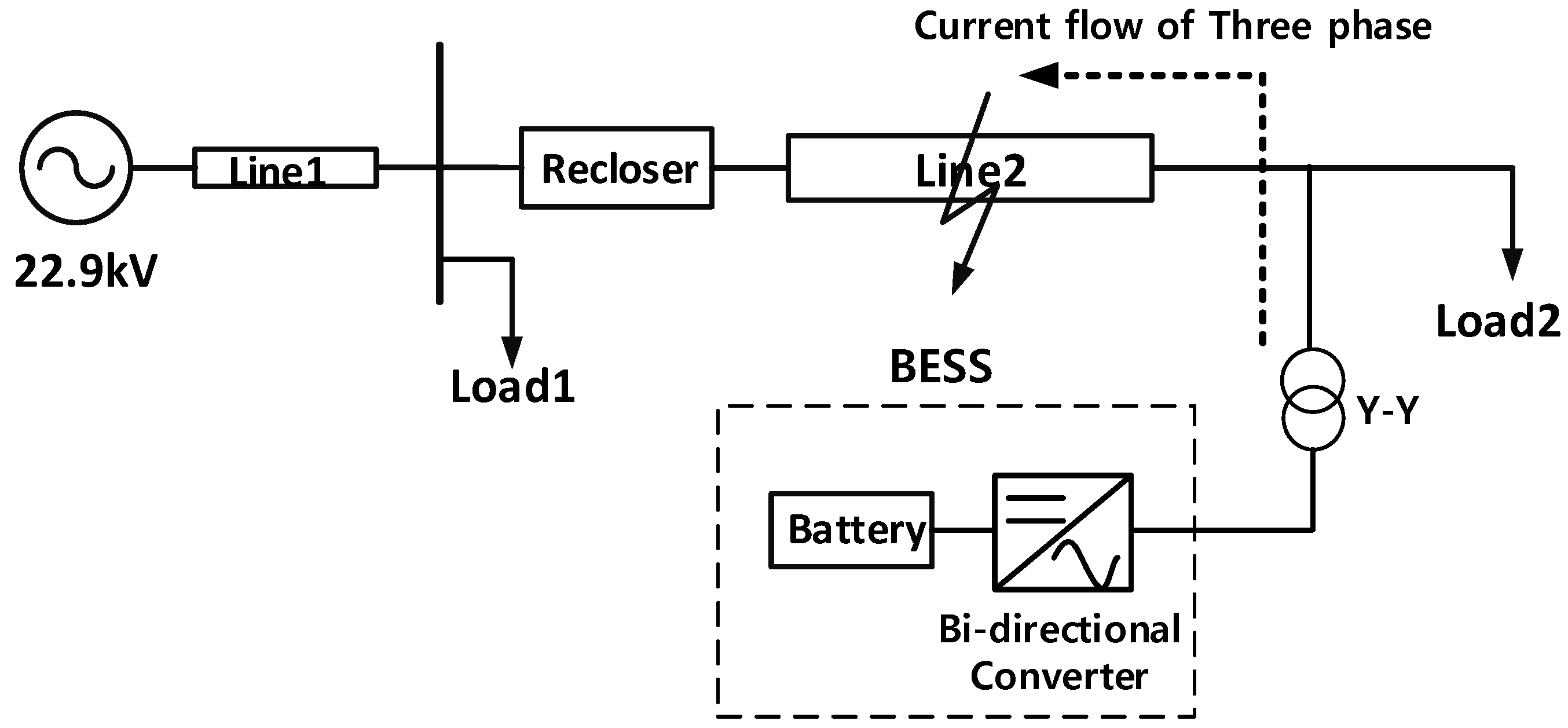
The new configuration of the distribution system to utilize the BESS as a UPS is presented in Figure 3. The BESS as a UPS is connected to the load side. The BESS is composed of a battery and bidirectional converter. The BESS supplies the power via a 380 V–22.9 kV Y-Y transformer to the distribution system. The bidirectional AC-DC converter works as the interface between the battery and the AC grid. The bidirectional converter receives the line voltage. It also delivers a DC charging voltage to the battery. In the event of an outage due to a fault, the battery will begin to discharge through the bidirectional converter. The DC voltage from the battery will be inverted to an AC voltage through the bidirectional converter. The inverted AC voltage is transformed to the proper distribution line voltage through a transformer. A lithium-ion (Li-ion) battery is adopted because it is sufficient for improving power system reliability and power quality. Batteries can be widely used in different applications, such as power quality, energy management, ride-through power, and transportation systems. It takes some time to start up a conventional generator. Therefore, it can’t be used as UPS. A typical UPS offers an instantaneous reaction, by supplying energy mostly stored in batteries, flywheels, or supercapacitors [16].
Among the available energy storage technologies, Li-ion batteries represent a suitable solution because of their features (i.e., fast response, high-power capability, long-cycle lifetime at partial cycles, and low self-discharge rate) [20]. A battery systems consist of a number of electrochemical cells connected in series or in parallel, which produce electricity with a desired voltage from an electrochemical reaction [16]. Li-ion batteries have been applied at various capacities in power systems. The US-based AES (Applied Energy Services) Energy Storage has been commercially operating an Li-ion BES system (8 MW/2 MWh in 2010, enlarged 16 MW in 2011) in New York for supplying frequency regulation. AES also installed a 32 MW/8 MWh Li-ion BES system (Laurel Mountain, PA, USA) for supporting a 98 MW wind generation plant in 2011. The largest European Li-ion BESS trial is underway in the UK. The project will deploy a 6 MW/10 MWh Li-ion battery at a primary substation to assess the cost effectiveness of BESS as part of the UK’s Carbon Plan [16]. As shown by the above application examples, large capacity Li-ion batteries have been applied in power system areas. Therefore, it is possible to determine the capacity requirement of battery by connecting cells in series or parallel to satisfy the sizing of the battery.
The differences comparing with conventional distribution system are as follows:
- (1)
- Replacement of the recloser with a CB and a protective relay.The recloser is a device that interrupts the circuit using only the increase of the fault current and performs the reclosing operation after the fixed dead time. However, in order to perform the reclosing procedure, considering the BESS proposed in this paper, it is necessary to simultaneously open/close the CB at the load side. Additionally, it is possible to judge whether or not the fault is cleared by using the small load current. These functions are not possible in the conventional recloser. Therefore, this paper proposes to replace this with the CB and a protection relay.
- (2)
- Installation of CBs at both sides of the distribution line.The conventional distribution system only has the recloser at the main source side. Assuming that the BESS supplies the steady-state power to the load after opening of the recloser due to a fault in conventional configuration. Load 1 will be supplied by the 22.9 kV source and load 2 will be supplied by the BESS when a fault occurs. The current from the BESS in the faulted phase among three phases flows to the fault point and no current flows to load 2. If a three phase to ground fault occurs, as shown in Figure 4, all currents flow to the fault point. If a single-line or double-line to ground fault occurs, as shown in Figure 5, the current of the faulted phase flows to the fault point and the current of the healthy phase flows to load 2. If three phase loads exist, they cannot receive the steady state power from the BESS during the fault. This is a disadvantage of the conventional configuration. Therefore, to block the current flow to the fault point, this paper proposes the new configuration of the distribution system where the CB at the load side (CB2 in Figure 3) is additionally installed. CBs are typically more expensive compared to reclosers. However, on the other hand, the economic effects, such as a reduction of the compensation cost by the reduction of outage times will also appear. Since the purpose of this study is to improve the operational ability in distribution systems with a large-capacity BESS, the economic analysis is not considered.
- (3)
- Requirement of a communication method.In the conventional reclosing scheme, the protection relay transmits a trip command to only one breaker. However, in the proposed method, CB1 and CB2 must be tripped at the same time. In addition, the voltage and current at the main source side and the voltage and current at the load side must be simultaneously inputted to the protective relay. Therefore, the communication method is required to receive two inputs at the same time and transmit the open/close signals to CB1 and CB2 as an output.
3.2. Novel Reclosing Procedure Considering the BESS
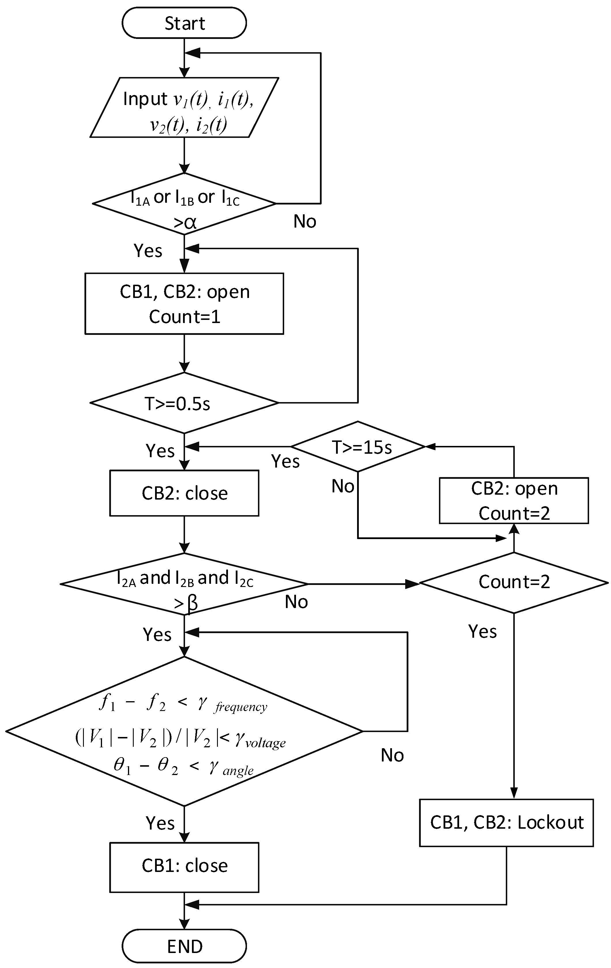
The flowchart of the novel reclosing procedure in the configuration of Figure 3 is shown in Figure 6. First, if the current (i1(t)) received from the main source side rises above a certain value (α), the fault occurrence is judged and, hence, both CB1 and CB2 are tripped simultaneously. In Figure 6, α is a threshold value for determining the fault occurrence. When this operation is completed, the normal power from the BESS is supplied to load 2. In Figure 6, count = 1 means that a preparation to try the first reclosing is completed. When the predetermined fixed dead time (0.5 s) elapses, CB2 is reclosed. After that, the fault clearance is judged using the load current. If the fault is cleared, the steady-state current from the BESS are supplied to all three phases of load 2 in Figure 3.
However, if the fault is not removed, the current at the faulted phase will flow to the fault point as shown in Figure 7 and a very small current will flow to load 2. These conditions can be used to determine whether or not the fault is cleared. In Figure 6, β is a threshold value to determine the fault clearance using load current. If a normal current larger than β flows in all three phases, it can be judged that the fault is cleared. If the fault is not cleared, a current smaller than β of the faulted phase flows to the load because the current flows to the fault point as shown in Figure 7.
The threshold value α is used for determining the fault occurrence. This value can be determined larger than two times that of the steady-state current. β is a threshold value to determine the fault clearance using the load current. This value can be determined as 0.7 times that of the steady-state current. They are dependent on the system conditions. In this paper, α and β are set as 110 and 40 for the simulations, respectively.
If it is judged that the fault is cleared, the differences between the magnitude, phase angle, and frequency using the main source and the load side voltage (v1(t), v2(t)) are calculated to perform a synchronism check. When the synchronism check is completed, CB1 is reclosed and the proposed reclosing procedure is terminated. If it is judged that the fault is not cleared, CB2 is opened again. In Figure 6, count = 2 means that a preparation to try the second reclosing is completed. After the fixed dead time (15 s) for the second reclosing has elapsed, the reclosing of CB2 is attempted again. Using the same method at the first reclosing, whether or not the fault is removed is judged. If it is judged that the fault is removed, the synchronism check is performed. After that, CB1 is reclosed when the synchronism check is completed. On the other hand, if the fault is not removed, it is judged as a permanent fault and, hence, CB1 and CB2 are locked out. The items for synchronism checking are the difference of voltage magnitude, voltage angle, and frequency between the main source and the load side. The threshold values γfrequency, γvoltage, and γangle for synchronism checking are independent of the system conditions and these values are determined based on [21]. γfrequency, γvoltage, and γangle are set to 0.2 Hz, 5%, and 15 degrees, respectively, in the simulations.
The conventional fault clearing and reclosing procedure performs the opening of the recloser when the large fault current is detected, and the closing of the recloser after a fixed dead time. If the fault is not cleared, it is opened again and the large fault current will flow to the fault point again. If these procedures are repeated, the electrical installation will be damaged and their lifetime will also be reduced. To solve this problem, this paper proposes the reclosing of CB2 rather than CB1 as the first order of business. Since the magnitude of the fault current supplied from the BESS is limited by the bidirectional converter, the magnitude of the fault current from the BESS is smaller than that of the fault current supplied from the main source. Therefore, if the proposed procedure is proposed, the electrical installation will be protected from damage caused by a large fault current.
4. Simulation
4.1. System Model
In this paper, EMTP/ATPDraw (developed by Hans Kr. Høidalen, Norway) is used for modeling the system model. The EMTP is the tool used to simulate transient electromagnetic phenomena, and it is one of the most widely used programs throughout electric utilities. ATPDraw is a graphical, mouse-driven pre-processor to the Alternative Transients Program (ATP) version of EMTP. MODELS in ATP is a general-purpose description language supported by an extensive set of simulation tools for the representation and study of time-variant systems. MODELS provides the monitoring and controllability of power systems, as well as some other algebraic and relational operations for programming [22,23].
The system model in Figure 3 is used to verify the proposed reclosing procedure. In Figure 3, the capacities of the BESS, load 1, and load 2 are 1000 kWh, 1000 kW, and 3000 kW, respectively. The length and type of line 1 and 2 are, equally, 10 km and aluminum conductor steel-reinforced cable 95 mm2, respectively. The distribution model with two CBs at both sides of the line, the BESS, and the proposed reclosing procedure are modeled by EMTP/ATPDraw. The sending and receiving of data for communication are implemented by input and output between sub-models in the EMTP/MODELS [22,23].
4.2. Simulation Conditions
Table 1 shows the simulation conditions used to verify the proposed reclosing technique. In the steady state, the BESS is fully charged until 1 s and is discharged after 1 s. This condition is associated with the fault occurrence time. The faults can occur at any time during the charging state of the BESS. However, this paper assumes the BESS has enough capacity to supply the current to the healthy phases and, hence, only simulates the fault occurrence after fully charging. Cases 1 and 2 are the transient fault, while Case 3 is a permanent fault. Case 1 is the condition to verify a first reclosing attempt. Case 2 is the condition to verify a second reclosing attempt.
The fault type is a single line-to-ground fault in phase A, the fault resistance is 1 Ω, and the fault location is 5 km along line 2 in Figure 3. In Cases 2 and 3, the dead time for the second reclosing attempt is set to 0.5 s instead of 15 s for the convenience of the simulations.
4.3. Simulation Results and Discussion
To analyse the simulation results, the load currents, voltage, and frequency waveforms are presented. The meanings of the numbers in each waveform shown in this paper are as follows:
- (1):
- Fault occurrence
- (2):
- Open of CB1 and CB2 at the same time
- (3):
- Fault clearance
- (4):
- First reclosing attempt of CB2
- (5):
- Reclosing of CB1 when the first reclosing of CB2 is successful, i.e., the fault is cleared
- (6):
- Re-open of CB1 when the first reclosing of CB2 is not successful, i.e., the fault is not cleared
- (7):
- Second reclosing attempt of CB2
- (8):
- Reclosing of CB1 when the second reclosing of CB2 is successful, i.e., the fault is cleared
- (9):
- Re-open of CB1 when the second reclosing of CB2 is not successful, i.e., the fault is not cleared
4.3.1. Case 1
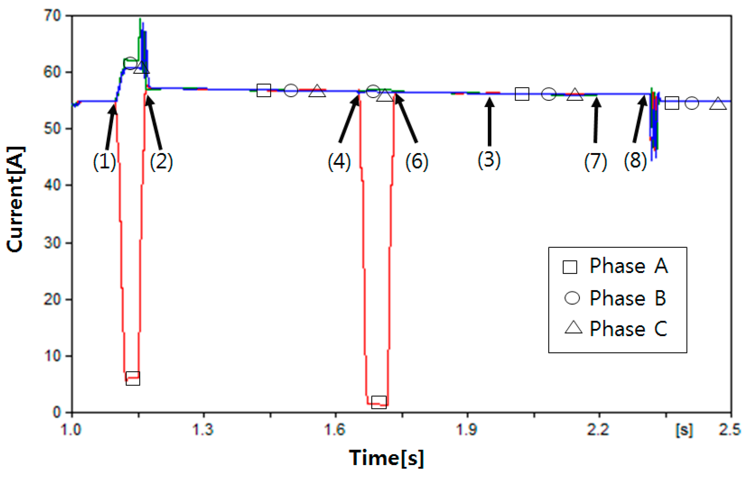
Figure 8 shows the root-mean-square (RMS) waveform of the load current in Case 1. When the fault occurs at 1.1 s, the value of the load current at the faulted phase becomes very small because a current flows to the fault point. The steady-state current by BESS is supplied to the load after two breakers are opened at 1.15 s. The reclosing of CB2 according to the proposed reclosing procedure is performed at 1.65 s. In this case, the fault clearance is judged by the proposed reclosing procedure and, hence, the synchronism check is performed. The reclosing of CB1 is successfully performed at 1.75 s after the synchronism check of CB1 is completed. When the reclosing of CB1 is performed, the fluctuation of the RMS current is observed, however, the normal load current flows again after about two cycles.
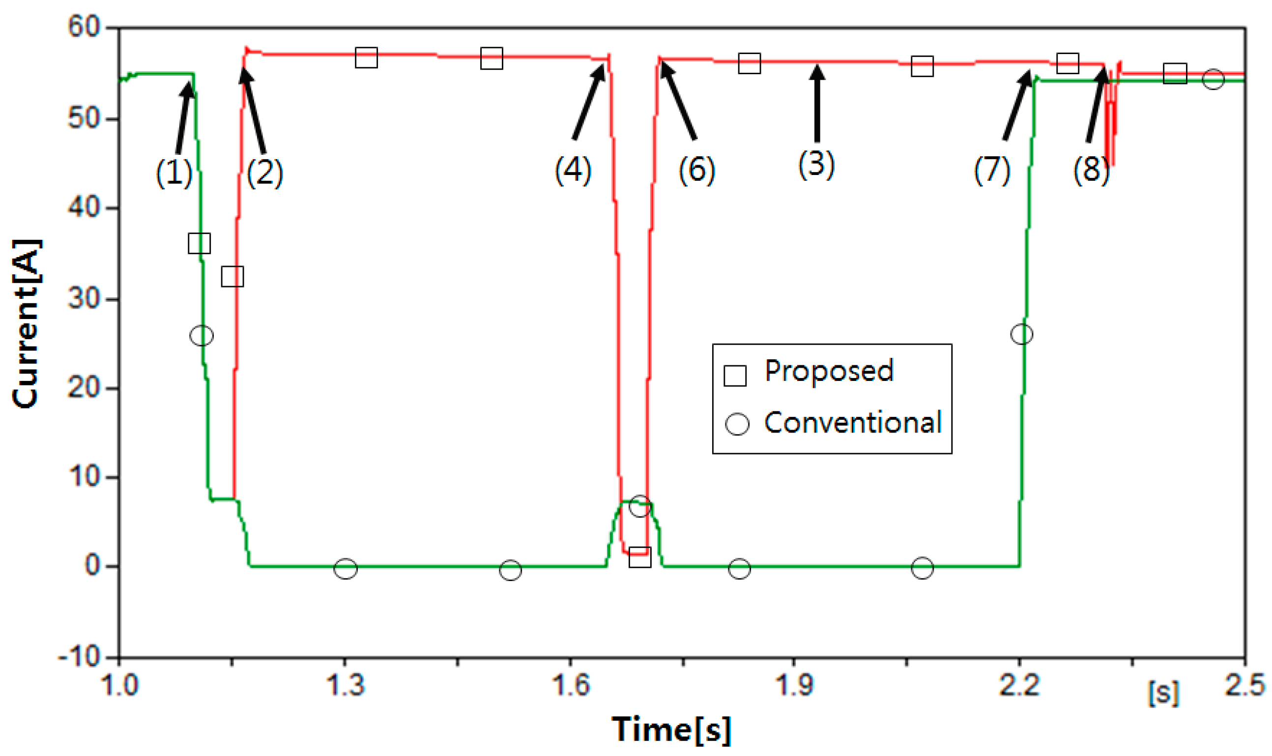
Figure 9 shows the comparison of proposed reclosing with conventional reclosing in Case 1. This is only a comparison of phase A, which is a faulted phase. In the proposed reclosing method, the steady-state current by the BESS is supplied to the faulted phase after opening CB2. In the conventional reclosing method, however, the current is zero before reclosing. The comparison results of the healthy phases are similar with this result. Therefore, the outage time will be reduced by the proposed reclosing method.
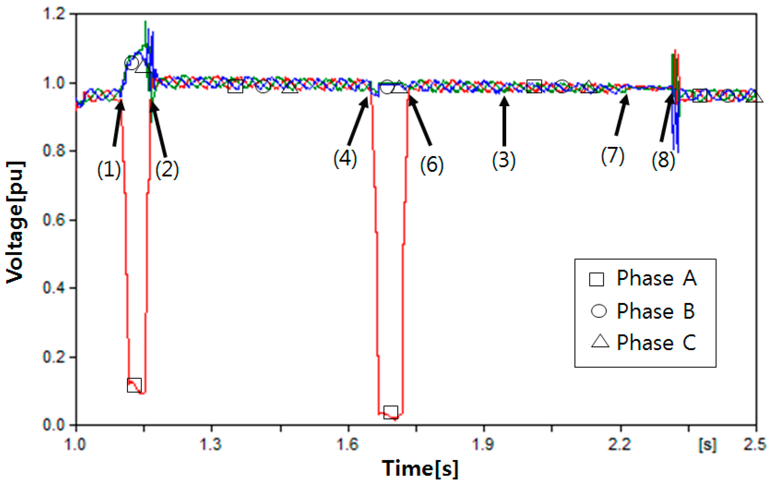
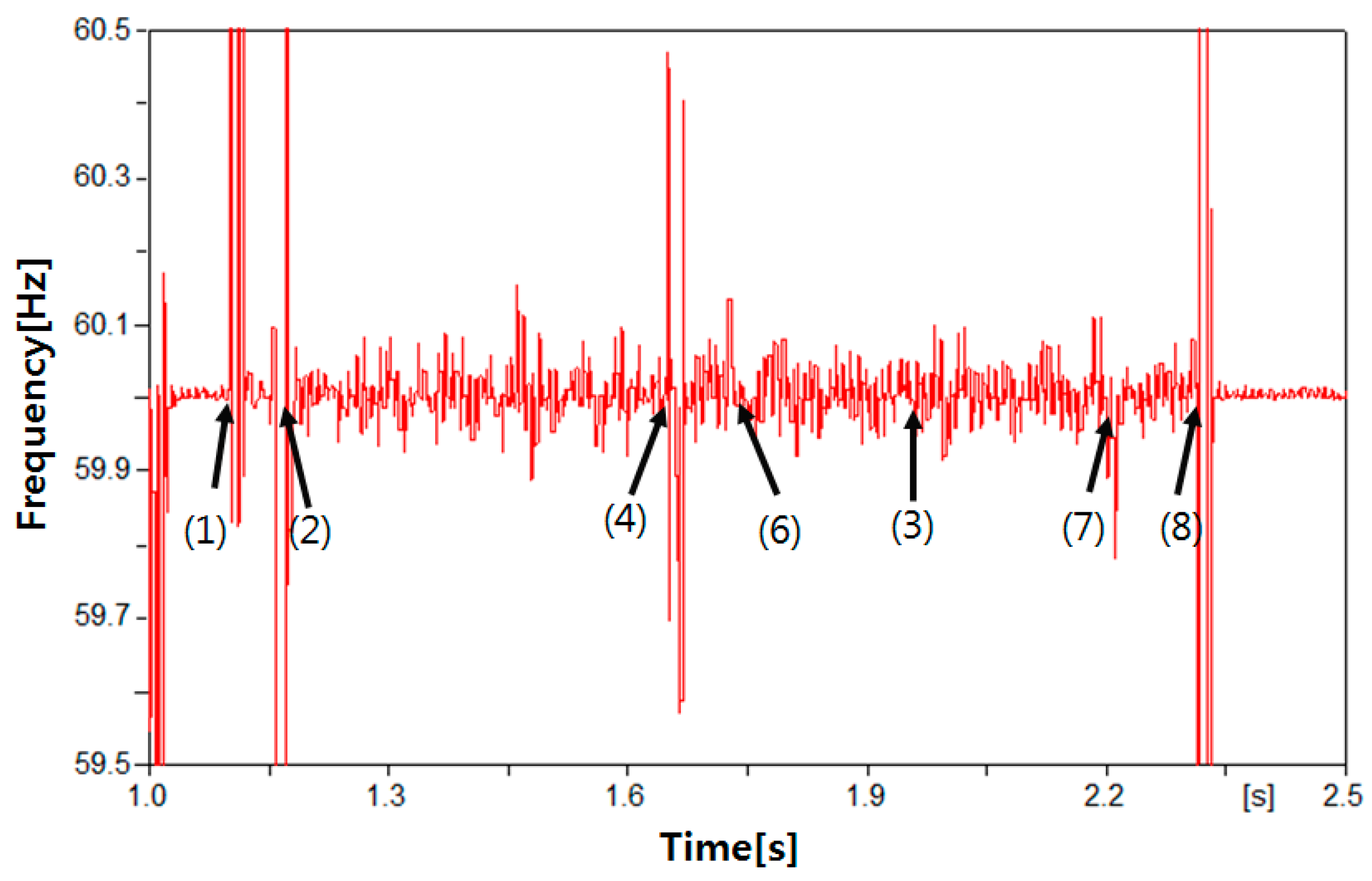
Figure 10 and Figure 11 show the load voltage and frequency waveform, respectively. Except for the instant when an event occurs, a voltage value less than 1.02 p.u. with the normal range appears and a frequency value in the normal range (59.8–60.2 Hz) appears. In Figure 10, the voltage fluctuation at reclosing instant of CB1 is observed. However, the steady-state voltage appears again after about two cycles. In Figure 11, the frequency at the reclosing instant of CB2 and CB1 is out of the normal range, but it is also returns to the normal range after two cycles.
Therefore, unlike the conventional reclosing method, the power having normal current, voltage, and frequency is supplied to the load by the BESS and, hence, it does not experience the outage.
4.3.2. Case 2
Figure 12 shows the RMS waveform of the load current in Case 2. After opening CB1 and CB2 due to the fault, it can be seen that the normal current is supplied to the load. The first reclosing of CB2 is attempted at 1.65 s, however, the load current is low and, hence, the CB2 is opened again according to the proposed reclosing procedure. After that, the normal current is supplied to the load again. The second reclosing of CB2 is attempted at 2.2 s after the fixed dead time and it is successful because of fault clearance. Therefore, the CB1 is reclosed at 2.31 s after synchronism checking.
Figure 13 shows the comparison of the proposed reclosing with the conventional reclosing in Case 2. This is only a comparison of phase A, which is a faulted phase. In the proposed reclosing method, except first reclosing attempt, the steady-state current by BESS is supplied to the faulted phase. In the conventional reclosing method, however, the current is zero before success of the second reclosing. The comparison results of the healthy phases are similar with this result.
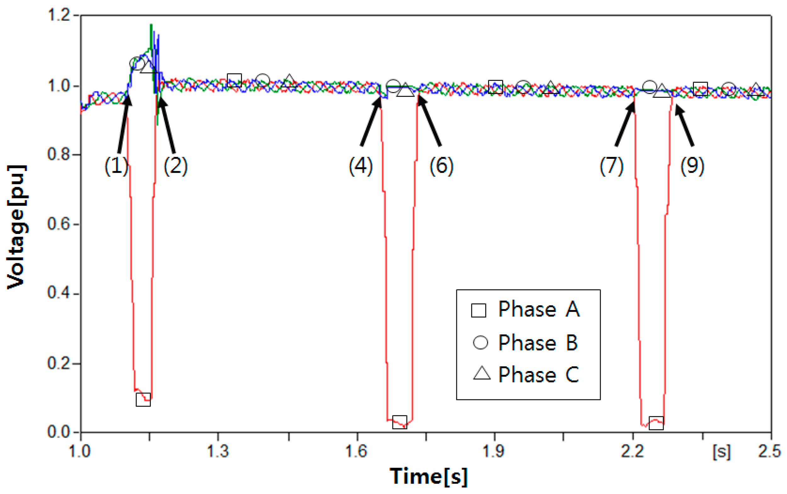
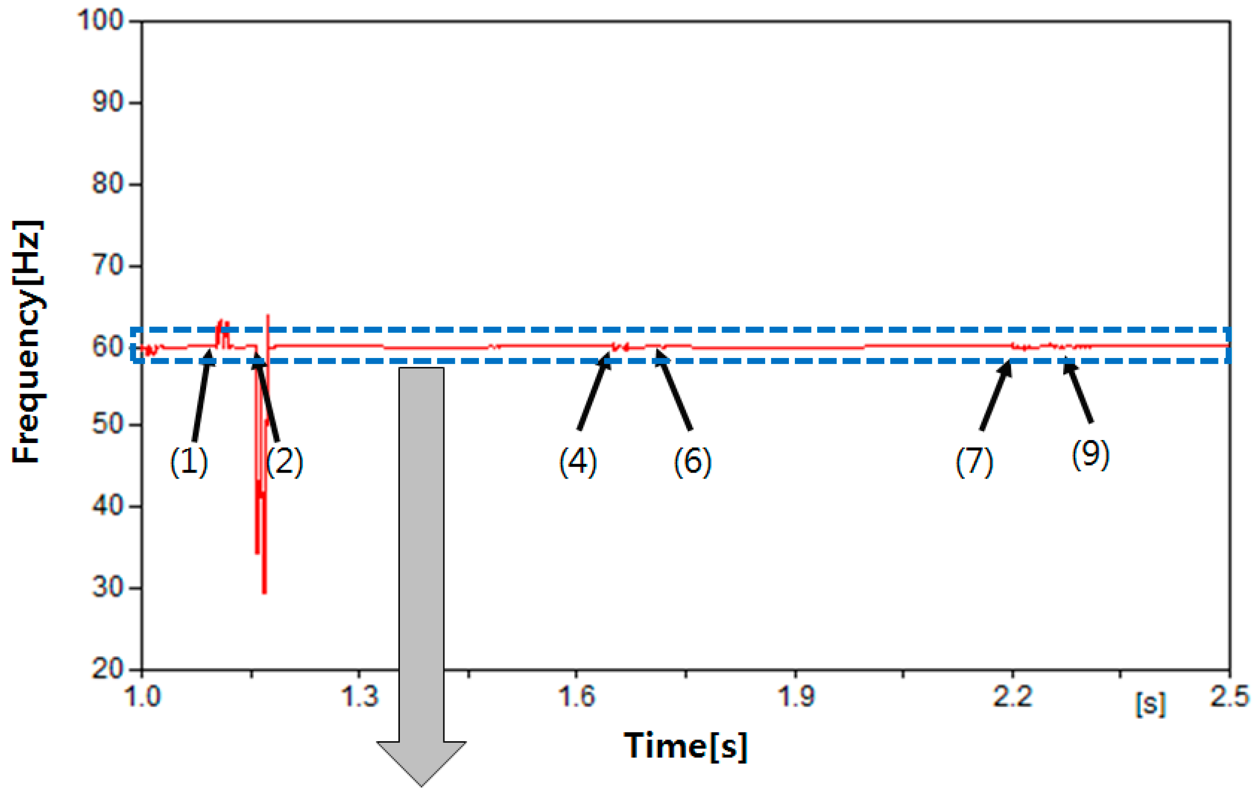
Figure 14 shows the RMS waveform of the load voltage in Case 2. After opening of breakers CB1 and CB2, a steady-state voltage of 0.98–1.02 p.u. appears in all three phases. When attempting the first reclosing, the load voltage on the faulted phase A drops, but the voltage in the normal range appears again after CB2 is re-opened. After the successful second reclosing of CB2, CB1 is reclosed at 2.31 s. The RMS value fluctuates due to the reclosing of CB1; however, the normal voltage appears again after two cycles. Figure 15 shows the frequency at the load point. Except for the transients by reclosing, the frequency within the normal range between 59.8 and 60.2 Hz appears. Therefore, load 2 does not experience the outage.
4.3.3. Case 3
Figure 16 shows the load current waveform in Case 3, which is a permanent fault. Since the load current in the faulted phase was low during the first and second reclosing attempts, CB2 is re-opened according to the proposed reclosing procedure. If the conventional reclosing procedure is applied, the load experiences the outage during the dead time. However, in the proposed reclosing procedure, because the power is normally supplied to the load by the BESS after the circuit breaker is opened, the load does not experience the outage.
Figure 17 shows the comparison of the proposed reclosing with the conventional reclosing in Case 3. This is only a comparison of phase A, which is a faulted phase. In the proposed reclosing method, the steady-state current by the BESS is supplied to the faulted phase, except two numbers of the reclosing attempt. In the conventional reclosing method, however, the steady-state current does not supply the loads. The comparison results of healthy phases are similar with this result.
Figure 18 and Figure 19 show the RMS voltage and frequency waveform of the load in Case 3. After the tripping of the CB, during the dead time, except for the first/second reclosing instant, the voltage is maintained at 0.98–1.02 p.u. and the frequency is maintained at 59.8–60.2 Hz. These values are in the steady-state range. When the first and second reclosing are attempted, the voltage at faulted phase A is dropped because the fault current flows to the faulted point and the frequency is also out of range. However, after re-opening of the CB, the voltage and frequency are, again, maintained in the steady-state range.
Therefore, despite the permanent fault, the normal power by the BESS is supplied to the load. If the power stored in the BESS is not sufficient during a permanent fault, the BESS cannot supply power and the steady state frequency and voltage cannot be maintained. In this case, the BESS should be disconnected from the distribution system for the restoration of a permanent fault.
5. Conclusions
The topic of this paper is related with the system operating strategies affected from sustainable energy generation for smart grid. In this paper, we propose the new configuration and novel reclosing procedure of a distribution system utilizing a BESS as a UPS in a smart grid. The proposed configurations are (1) replacement of the recloser with a CB and protective relay; (2) the installation of a CB on both ends of the distribution line; and (3) the requirement of a communication method. Based on these configurations, this paper proposes a novel reclosing method considering the BESS. When the fault occurs, the CBs at both ends of the distribution line are opened at the same time, and then normal power is supplied to the load by the BESS. The reclosing of the CB at the load side is firstly attempted, and then the fault clearance using the magnitude of the load current is judged. If it is judged that the fault is removed, a synchronism check between the power supplied by the BESS and the power supplied by main source is performed. When this is completed, the CB at the main source side is reclosed.
To verify the proposed method, the proposed system configuration and reclosing procedure are modeled by EMTP/ATPDraw. The simulations according to the fault clearance time are performed and the load current, voltage, and frequency waveforms are analyzed. After opening the CBs, we can find that the normal current and voltage/frequency within the normal range are supplied to the load by the BESS. In other words, according to the proposed reclosing procedure, the successful reclosing is performed and the BESS can be operated as a UPS.
As distributed generations are emerging in the distribution network, it is very important for the system operator to consider bidirectional power flow, and determine the fault detection and clearing scheme. As a future study, therefore, we will perform the reclosing study considering distributed generation and BESS.
Author Contributions
Hun-Chul Seo conceived, designed and performed the experiments, analyzed the data, and wrote the paper.
Conflicts of Interest
The author declares no conflict of interest.
References
- Shariatkhah, M.-H.; Haghifam, M.-R.; Chicco, G.; Mohsen, P.-M. Modelling the operation strategies of storages and hydro resources in adequacy analysis of power systems in presence of wind farms. IET Renew. Power Gener. 2016, 10, 1059–1068. [Google Scholar] [CrossRef]
- Brekken, T.K.A.; Yokochi, A.; von Jouanne, A.; Yen, Z.Z.; Hapke, H.M.; Halamay, D.A. Optimal Energy Storage Sizing and Control for Wind Power Applications. IEEE Trans. Sustain. Energy 2011, 2, 69–77. [Google Scholar] [CrossRef]
- Li, X.; Hui, D.; Lai, X. Battery Energy Storage Station (BESS)-Based Smoothing Control of Photovoltaic (PV) and Wind Power Generation Fluctuations. IEEE Trans. Sustain. Energy 2013, 4, 464–473. [Google Scholar] [CrossRef]
- Ju, L.; Tan, Z.; Yuan, J.; Tan, Q.; Li, H.; Dong, F. A bi-level stochastic scheduling optimization model for a virtual power plant connected to a wind-photovoltaic-energy storage system considering the uncertainty and demand response. Appl. Energy 2016, 171, 184–199. [Google Scholar] [CrossRef]
- Reihani, E.; Motalleb, M.; Ghorbani, R.; Saoud, L.S. Load peak shaving and power smoothing of a distribution grid with high renewable energy penetration. Renew. Energy 2016, 86, 1372–1379. [Google Scholar] [CrossRef]
- Diao, W.; Jiang, J.; Liang, H.; Zhang, C.; Jiang, Y.; Wang, L.; Mu, B. Flexible Grouping for Enhanced Energy Utilization Efficiency in Battery Energy Storage System. Energies 2016, 9, 498. [Google Scholar] [CrossRef]
- Atia, R.; Yamada, N. Distributed Renewable Generation and Storage System Sizing Based on Smart Dispatch of Microgrids. Energies 2016, 9, 176. [Google Scholar] [CrossRef]
- Zhou, H.; Bhattacharya, T.; Tran, D.; Siew, T.S.T.; Khambadkone, A.M. Composite Energy Storage System Involving Battery and Ultracapacitor with Dynamic Energy Management in Microgrid Applications. IEEE Trans. Power Electron. 2011, 26, 923–930. [Google Scholar] [CrossRef]
- Reihani, E.; Sepasi, S.; Roose, L.R.; Matsuura, M. Energy management at the distribution grid using a Battery Energy Storage System (BESS). Int. J. Electr. Power Energy Syst. 2016, 77, 337–344. [Google Scholar] [CrossRef]
- Zhou, N.; Liu, N.; Zhang, J.; Lei, J. Multi-Objective Optimal Sizing for Battery Storage PV-Based Microgrid with Demand Response. Energies 2016, 9, 591. [Google Scholar] [CrossRef]
- Wang, D.; Ge, S.; Jia, H.; Wang, C.; Zhou, Y.; Lu, N.; Kong, X. A demand response and battery storage coordination algorithm for providing microgrid tie-line smoothing services. IEEE Trans. Sustain. Energy 2014, 5, 476–486. [Google Scholar] [CrossRef]
- Liu, J.; Wen, J.; Yao, W.; Long, Y. Solution to short-term frequency response of wind farms by using energy storage systems. IET Renew. Power Gener. 2016, 10, 669–678. [Google Scholar] [CrossRef]
- Yang, J.-S.; Choi, J.-Y.; An, G.-H.; Choi, Y.-J.; Kim, M.-H.; Won, D.-J. Optimal Scheduling and Real-Time State-of-Charge Management of Energy Storage System for Frequency Regulation. Energies 2016, 9, 1010. [Google Scholar] [CrossRef]
- Lucas, A.; Chondrogiannis, S. Smart grid energy storage controller for frequency regulation and peak shaving, using a vanadium redox flow battery. Int. J. Electr. Power Energy Syst. 2016, 80, 26–36. [Google Scholar] [CrossRef]
- Serban, I.; Marinescu, C. Control Strategy of Three-Phase Battery Energy Storage Systems for Frequency Support in Microgrids and with Uninterrupted Supply of Local Loads. IEEE Trans. Power Electron. 2014, 29, 5010–5020. [Google Scholar] [CrossRef]
- Luo, X.; Wang, J.; Dooner, M.; Clarke, J. Overview of current development in electrical energy storage technologies and the application potential in power system operation. Appl. Energy 2015, 137, 511–536. [Google Scholar] [CrossRef]
- Seo, H.-C. New Reclosing Technique in Distribution System with Battery Energy Storage System. J. Korean Inst. Illuminating Electr. Install. Eng. 2016, 30, 21–27. [Google Scholar] [CrossRef]
- Seo, H.-C. New adaptive reclosing technique using second-order difference of THD in distribution system with BESS used as uninterruptible power supply. Int. J. Electr. Power Energy Syst. 2017, 84, 13–24. [Google Scholar] [CrossRef]
- Seo, H.-C.; Ko, Y.-T.; Rhee, S.-B.; Kim, C.-H.; Aggarwal, R.K. A Novel Reclosing Algorithm considering the Recovery Time of a Superconducting Fault Current Limiter in Distribution System with Distributed Generation. In Proceedings of the Institution of Engineering and Technology Conference on Developments in Power System Protection, Manchester, UK, 29 March–1 April 2010. [Google Scholar]
- Stroe, D.I.; Knap, V.; Swierczynski, M.; Stroe, A.I.; Teodorescu, R. Operation of a Grid-Connected Lithium-Ion Battery Energy Storage System for Primary Frequency Regulation: A Battery Lifetime Perspective. IEEE Trans. Ind. Appl. 2017, 53, 430–438. [Google Scholar] [CrossRef]
- Korea Electric Power Corporation. Technical Standard for Interconnecting Distributed Generation with Distribution System; Korea Electric Power Corporation: Naju, Korea, 2015. [Google Scholar]
- Kim, J.-H.; Lee, S.-J.; Kim, E.-S.; Kim, S.-K.; Kim, C.-H.; Prikler, L. Modeling of Battery for EV using EMTP/ATPDraw. J. Electr. Eng. Technol. 2014, 9, 98–105. [Google Scholar] [CrossRef]
- Kim, C.-H.; Lee, M.-H.; Aggarwal, R.K.; Johns, A.T. Educational Use of EMTP MODELS for the Study of a Distance Relaying Algorithm for Protecting Transmission Lines. IEEE Trans. Power Syst. 2000, 15, 9–15. [Google Scholar]
Figure 1.
Conventional configuration of the distribution system.
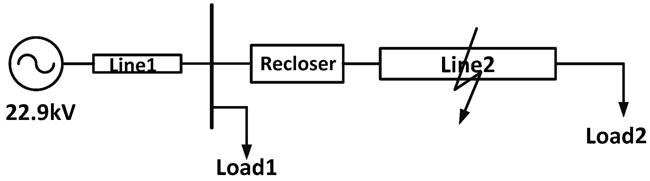
Figure 2.
Conventional reclosing procedure.

Figure 3.
New configuration of distribution system for the new reclosing technique. CB: circuit breaker; BESS: battery energy storage system.
Figure 3.
New configuration of distribution system for the new reclosing technique. CB: circuit breaker; BESS: battery energy storage system.
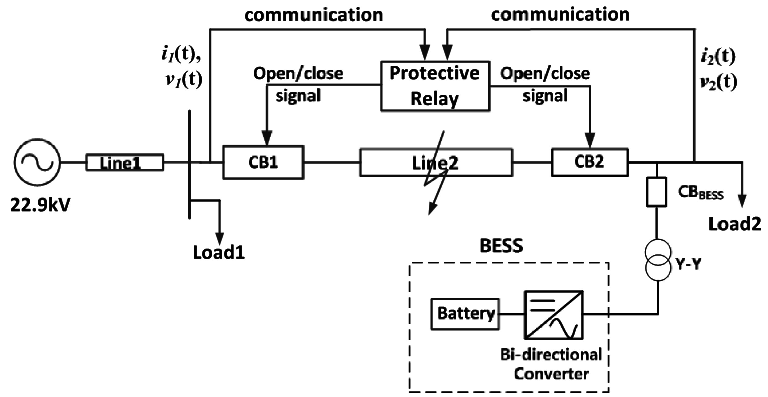
Figure 4.
Current flow from the BESS during three-phase to ground faults.

Figure 5.
Current flow from the BESS during single-line or double-line to ground faults.
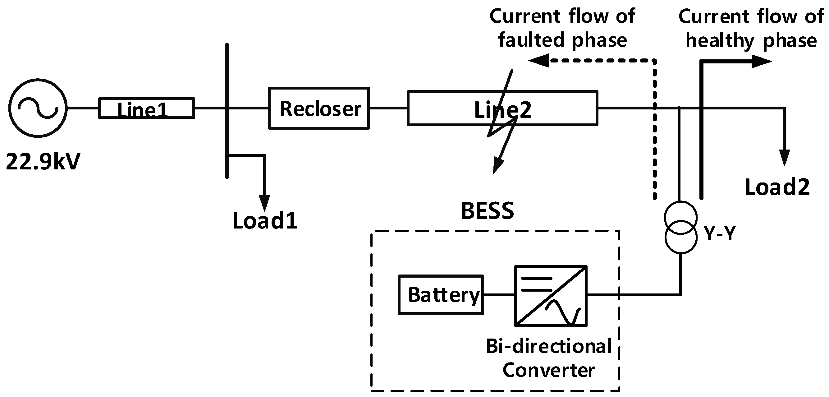
Figure 6.
Flowchart of the proposed reclosing method.

Figure 7.
Current flow after reclosing CB2.
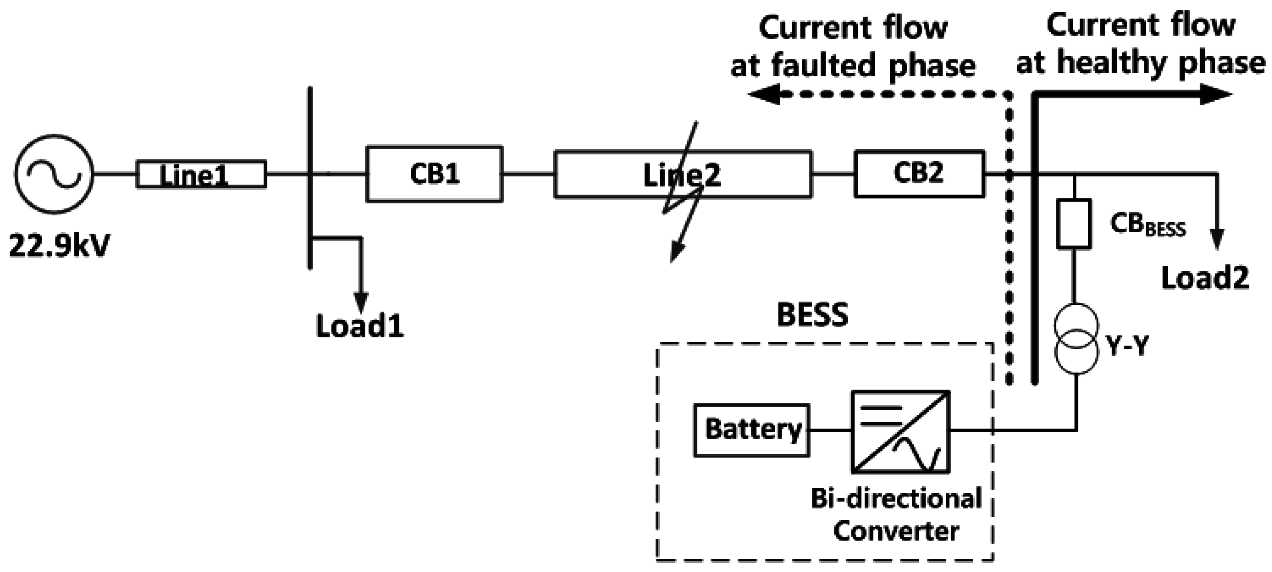
Figure 8.
Root-mean-square (RMS) waveform of the load current in Case 1.
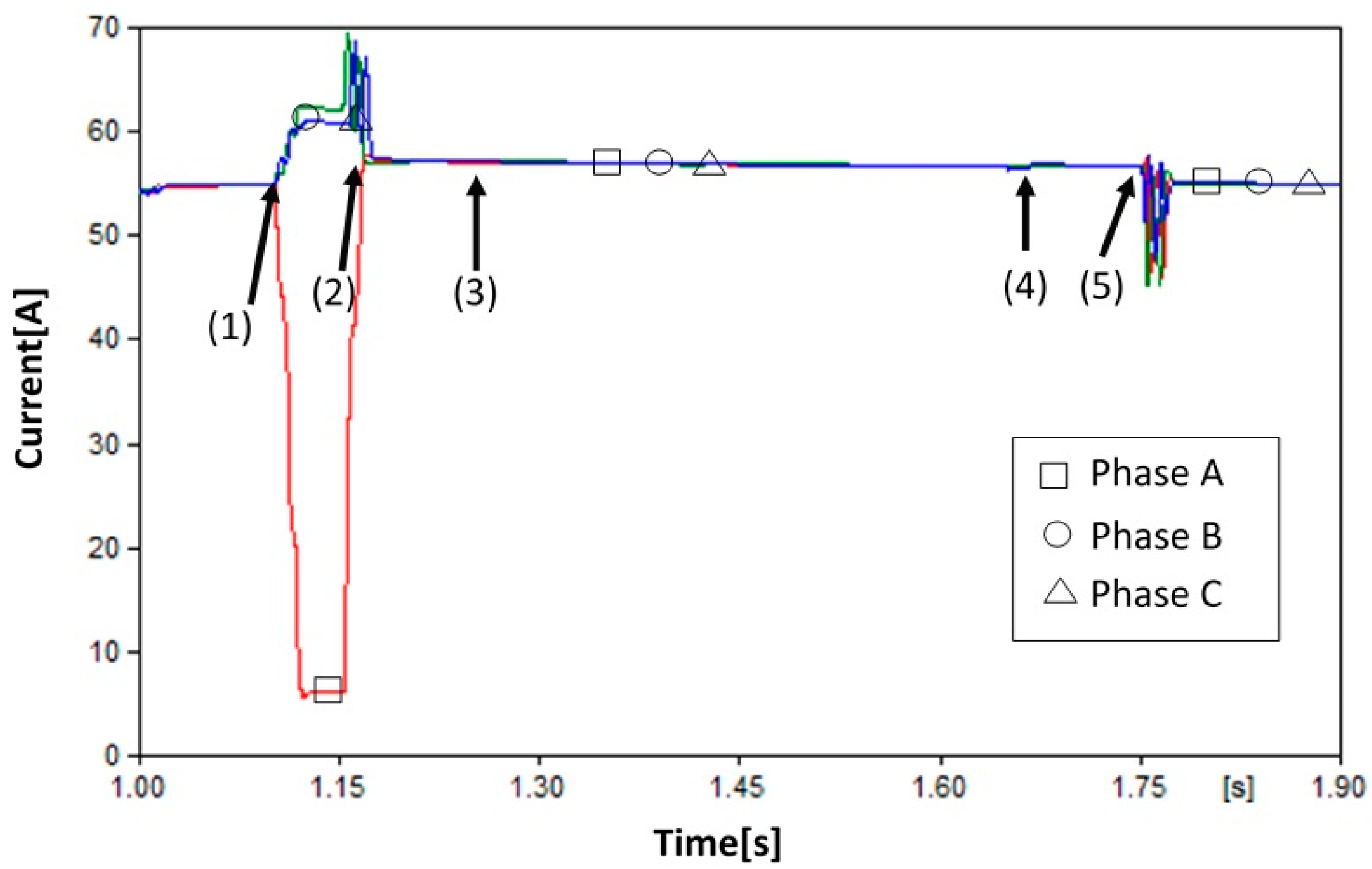
Figure 9.
Comparison of the proposed reclosing with the conventional reclosing in Case 1.
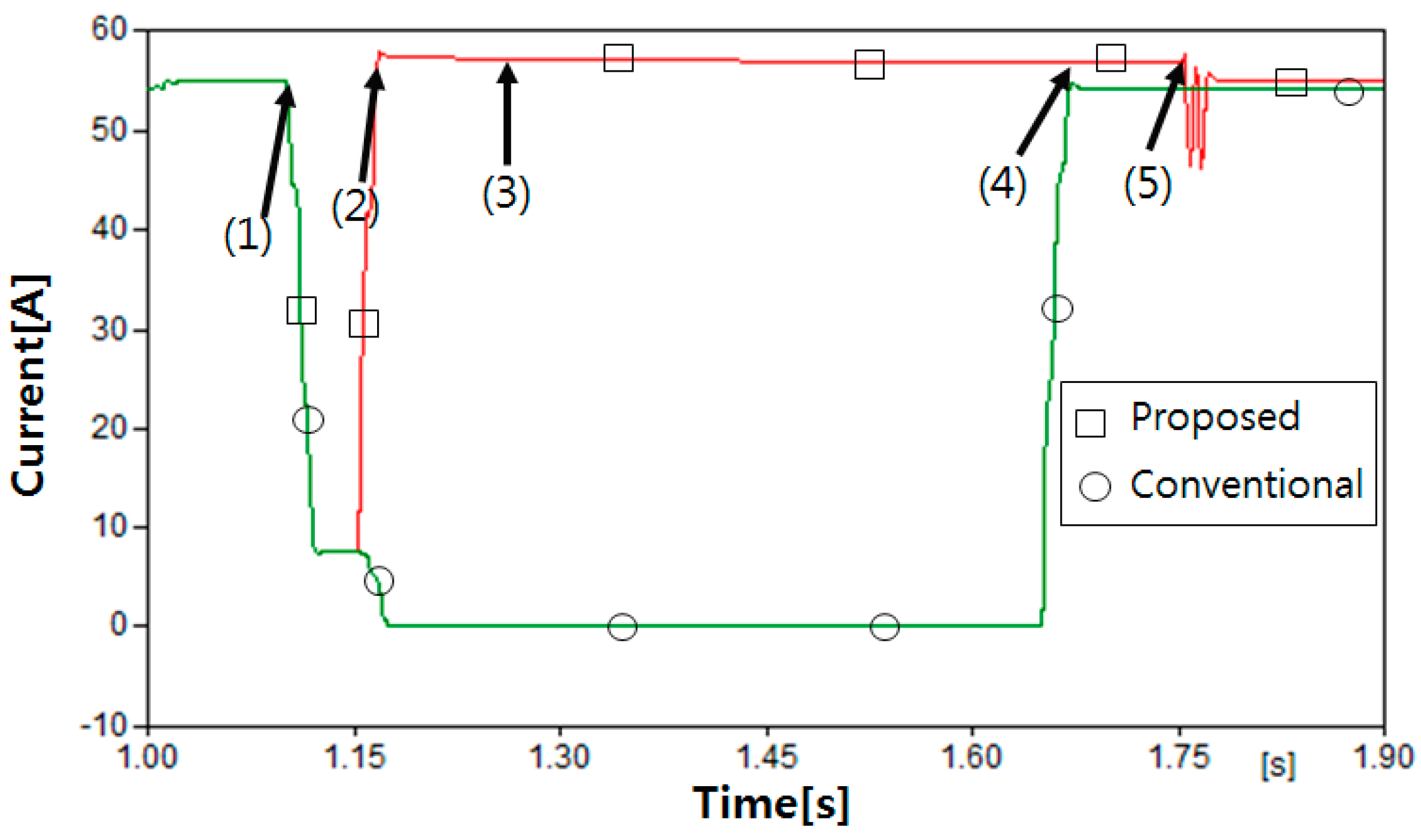
Figure 10.
RMS waveform of the load voltage in Case 1.
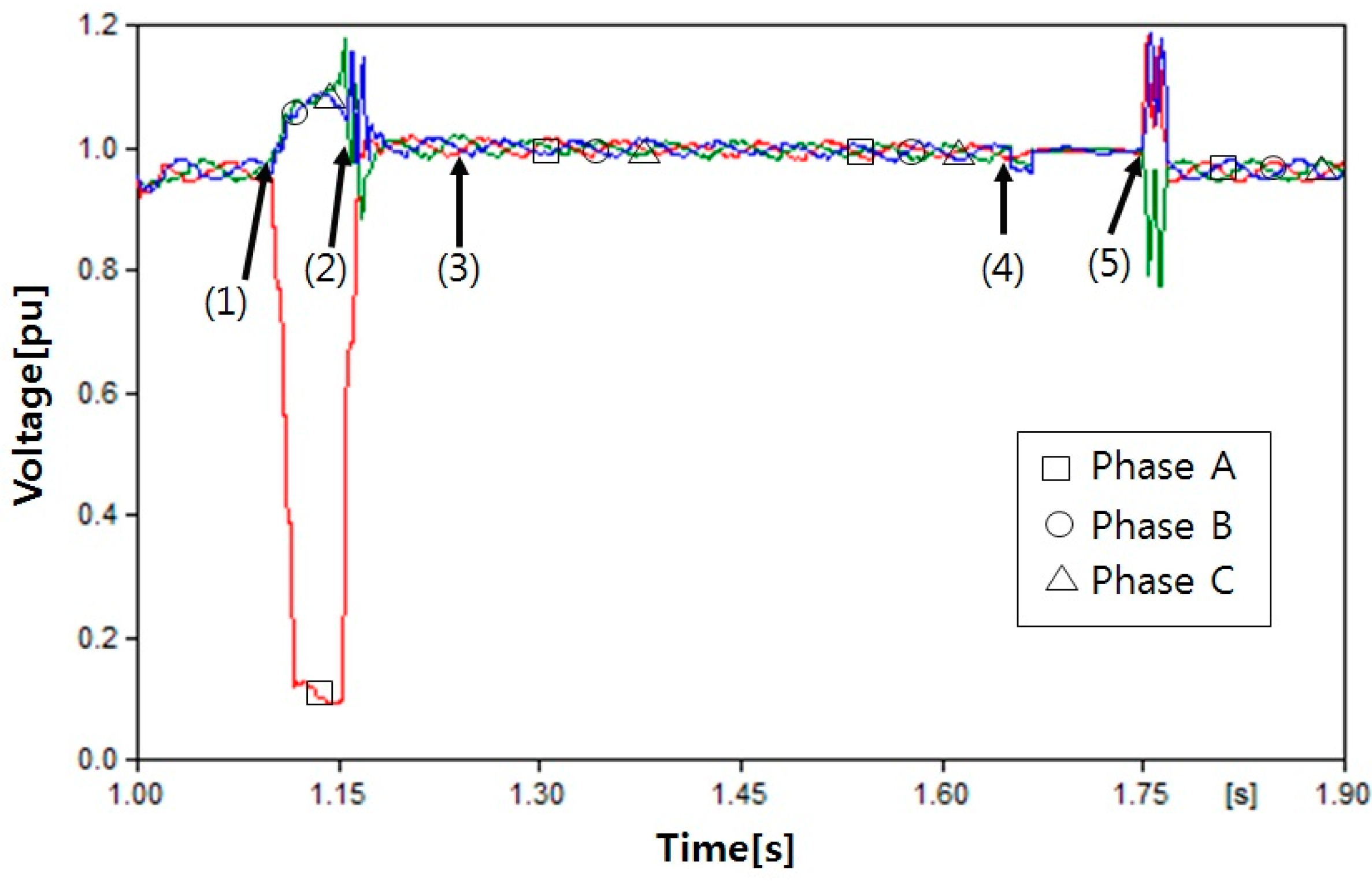
Figure 11.
Frequency waveform at the load in Case 1.

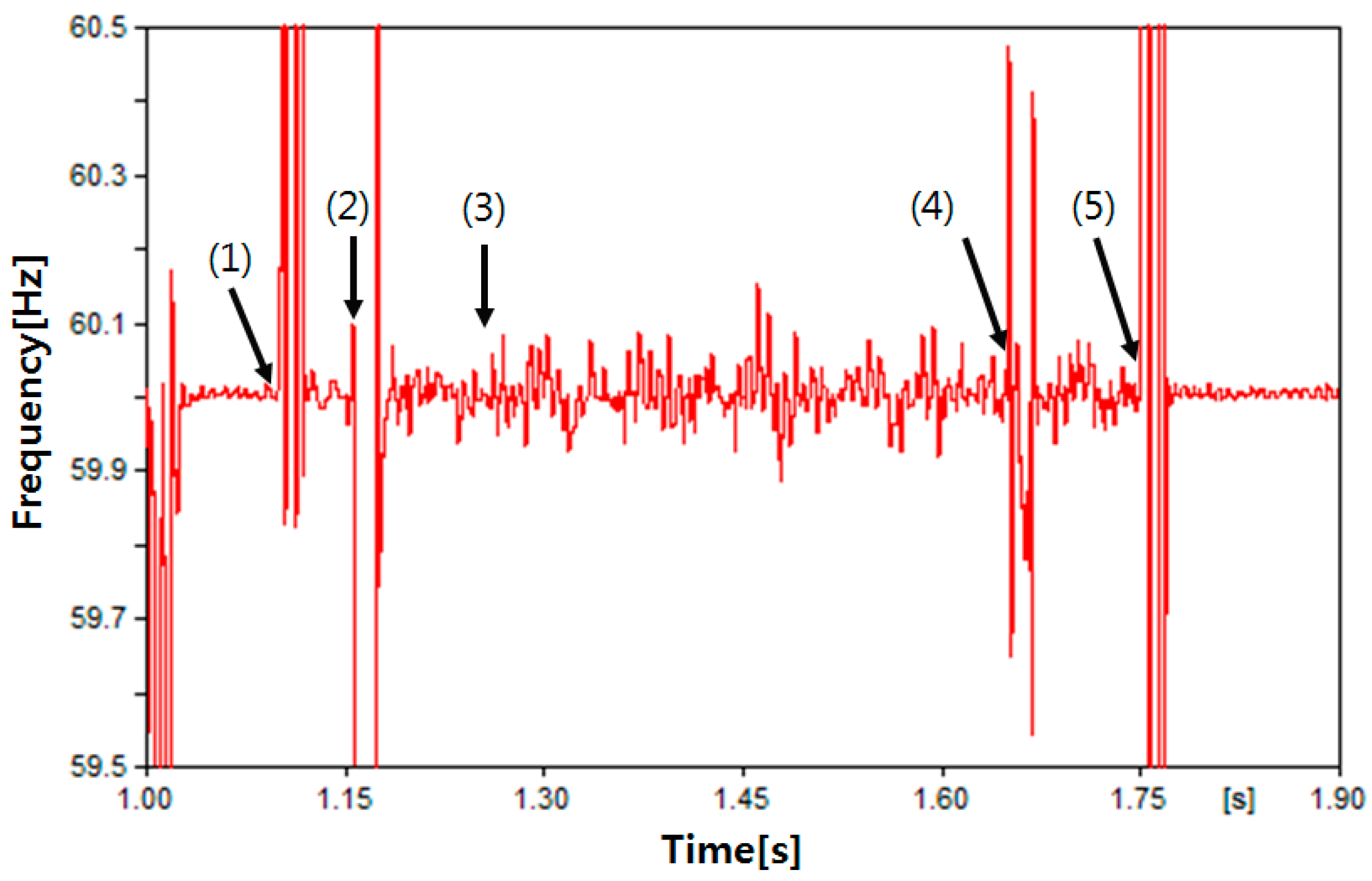
Figure 12.
RMS waveform of the load current in Case 2.

Figure 13.
Comparison of the proposed reclosing with the conventional reclosing in Case 2.

Figure 14.
RMS waveform of the load voltage in Case 2.

Figure 15.
Frequency waveform at the load in Case 2.
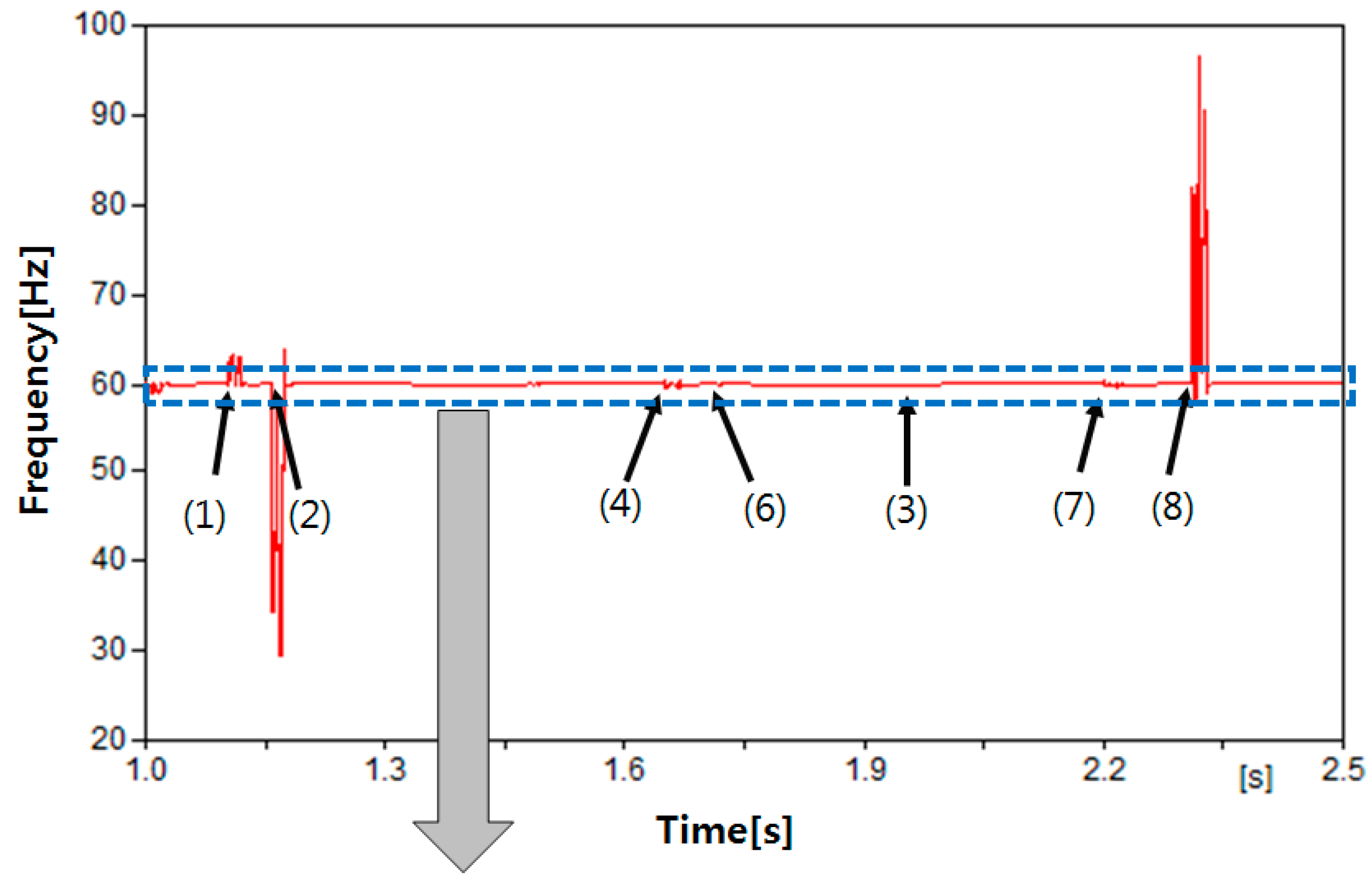

Figure 16.
RMS waveform of the load current in Case 3.
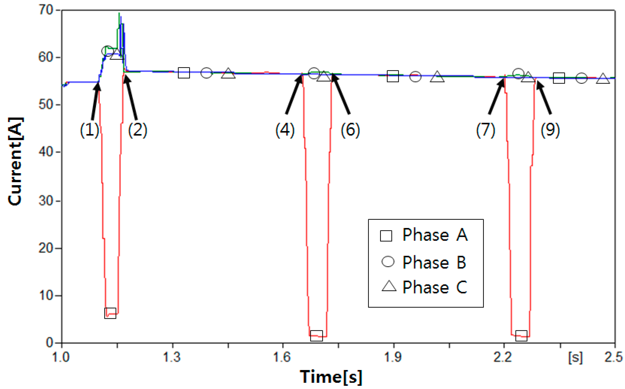
Figure 17.
Comparison of the proposed reclosing with the conventional reclosing in Case 3.
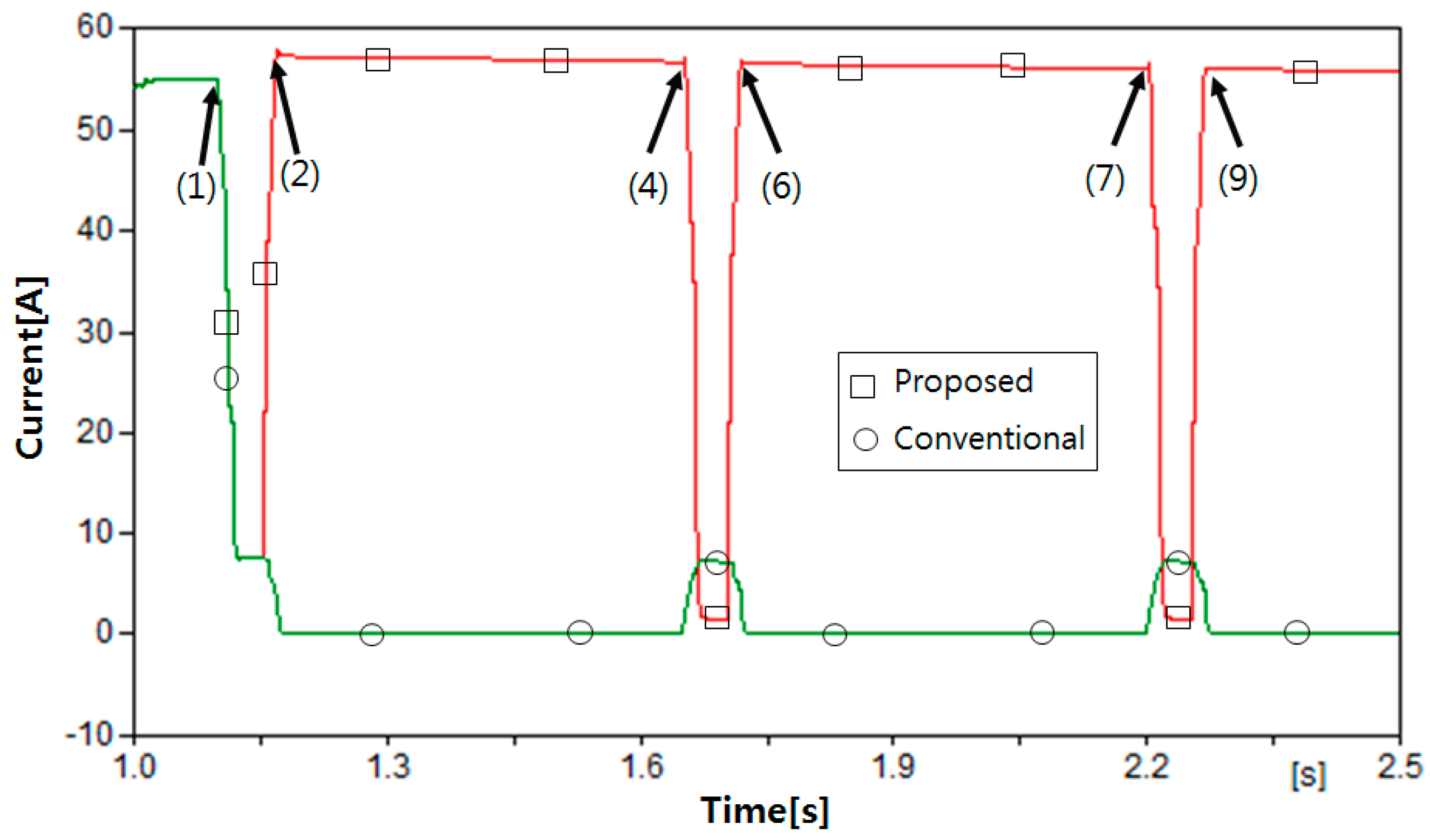
Figure 18.
RMS waveform of the load voltage in Case 3.

Figure 19.
Frequency waveform at the load in Case 3.


Table 1.
Simulation conditions.
| Case | Fault Occurrence [s] | Fault Clearance Time [s] | Description |
|---|---|---|---|
| Case 1 | 1.1 | 1.266 | Transient fault |
| Case 2 | 1.1 | 1.933 | Transient fault |
| Case 3 | 1.1 | – | Permanent fault |
© 2017 by the author. Licensee MDPI, Basel, Switzerland. This article is an open access article distributed under the terms and conditions of the Creative Commons Attribution (CC BY) license (http://creativecommons.org/licenses/by/4.0/).
Share and Cite
MDPI and ACS Style
Seo, H.-C. New Configuration and Novel Reclosing Procedure of Distribution System for Utilization of BESS as UPS in Smart Grid. Sustainability 2017, 9, 507. https://doi.org/10.3390/su9040507
AMA Style
Seo H-C. New Configuration and Novel Reclosing Procedure of Distribution System for Utilization of BESS as UPS in Smart Grid. Sustainability. 2017; 9(4):507. https://doi.org/10.3390/su9040507
Chicago/Turabian StyleSeo, Hun-Chul. 2017. "New Configuration and Novel Reclosing Procedure of Distribution System for Utilization of BESS as UPS in Smart Grid" Sustainability 9, no. 4: 507. https://doi.org/10.3390/su9040507
Note that from the first issue of 2016, this journal uses article numbers instead of page numbers. See further details here.