A Study on a Control Method with a Ventilation Requirement of a VAV System in Multi-Zone

1
Department of Architectural Engineering, Graduate School of Yeungnam University, 280 Daehak-Ro, Gyeongsan, Gyeongbuk 38541, Korea
2
School of Architecture, Yeungnam University, 280 Daehak-Ro, Gyeongsan, Gyeongbuk 38541, Korea
*
Author to whom correspondence should be addressed.
Sustainability 2017, 9(11), 2066; https://doi.org/10.3390/su9112066
Submission received: 8 August 2017
/
Revised: 28 October 2017
/
Accepted: 31 October 2017
/
Published: 10 November 2017
(This article belongs to the Section Sustainable Engineering and Science)
Abstract
:The objective of this study was to propose a control method with a ventilation requirement of variable air volume (VAV) system in multi-zone. In order to control the VAV system inmulti-zone, it is essential to control the terminal unit installed in each zone. A VAV terminal unit with conventional control method using a fixed minimum air flow can cause indoor air quality (IAQ) issues depending on the variation in the number of occupants. This research proposes a control method with a ventilation requirement of the VAV terminal unit and AHU inmulti-zone. The integrated control method with an air flow increase model in the VAV terminal unit, AHU, and outdoor air intake rate increase model in the AHU was based on the indoor CO2 concentration. The conventional and proposed control algorithms were compared through a TRNSYS simulation program. The proposed VAV terminal unit control method satisfies all the conditions of indoor temperature, IAQ, and stratification. An energy comparison with the conventional control method showed that the method satisfies not only the indoor thermal comfort, IAQ, and stratification issue, but also reduces the energy consumption.
1. Introduction
Buildings account for 25%, or more, of the entire amount of domestic energy consumption. Especially, mid-sized and large buildings continue to increase in energy consumption. These days, the reduction of greenhouse gases by energy saving is highlighted as an important issue. Accordingly, building facility systems should be operated to make sure that energy is used and saved efficiently.
The variable air volume system (VAV system) is adopted in many large buildings with increasing interest in energy saving and various studies have been performed for its efficient operation [1]. The common air conditioning system is designed to perform air conditioning in a plurality of zones using an air handling unit (AHU). A terminal unit is located in the end terminal that supplies air conditioned air to each zone, which makes it necessary to control a terminal unit in each zone in order to control a VAV system in multi-zone.
The systematic use of optimization techniques has been introduced in the heating, ventilation, and air conditioning (HVAC) industry in recent years, with a substantial focus on VAV system optimal control [2,3,4]. Yao et al. [5] compared three kinds of air conditioning systems (VAV, Constant Air Volume, and fan coil system) in small office buildings in six different cities in China. The parameters in the model were obtained from either the field-testing data or the performance data provided by the product manual. The VAV system promised 17.0–37.6% potential energy savings, compared to the CAV system, and 4.6–10.2% potential energy savings, compared to the fan coil system, depending on the location of the city and climate. Engdahl and Johansson [6] investigated the potential energy savings of a controlled supply air temperature of a VAV-based system by a comparison with a constant supply air temperature. The model results showed 8–27% potential energy savings for the varying supply air temperature case, compared to the constant supply air temperature case. Congradac and Kulic [7] used genetic algorithms to optimize the return damper position such that the indoor CO2 concentration can be kept as close to the desired level as possible and, at the same time, the lowest value of the valve (the lowest energetic use) can be achieved. Nassif and Moujaes [8] proposed a new damper control strategy for the outdoor, discharge, and recirculation air dampers of the economizer in a VAV system. The strategy controlled the outdoor air by only one damper while keeping the others fully opened. The simulation results showed that the annual energy savings in the supply and return fans of an existing system, compared to the traditional strategy of three coupled dampers, were 12% and 5%, respectively. Cho [9] examined the procedures for supply fan speed control, implementations and detailed descriptions of the control sequence, and operation comparisons. The results show electricity savings of 23% and gas savings of 19% over a six-month period. Cho [10] identified the relationship between the supply air temperature and minimum air flow rate. In addition, the relationship between the supply air flow rate and temperature that minimizes energy consumption was suggested through proper supply temperature, stratification, and energy analysis according to the load that energy consumption can be minimized.
CO2-based DCV have been proposed to determine the minimum outside air intake based on the number of occupants in the zone. The DCV for a single-zone have been studied by many researchers over the past few decades. Subsequently, Int-hout [11] proposed a more detailed control method, such as proportional control and PID control. Pavlovas [12] reported the results of a case study over a Swedish multifamily building aimed at evaluating the DCV system with different strategies. The outcome of the simulation shows that it would be possible to achieve energy savings using occupancy- and humidity-controlled ventilation to reduce the average ventilation flow rate while maintaining an acceptable indoor climate. Lu et al. [13] examined a new control strategy of CO2-based DCV for sports training arenas to address the challenge of control algorithms. The controlled CO2 concentration using the new strategy was close to the CO2 set point at each training session; therefore, the ventilation was optimized. Mysen et al. [14] inspected 157 Norwegian classrooms to analyze the energy use over there different ventilation systems: CAV, DCV-CO2, and infrared occupancy sensor-based demand-controlled system (DCVIR). Their results show that DCV-CO2 and DCV-IR reduce the energy use due to ventilation in an average classroom to 38% and 51%, respectively, compared to the corresponding energy for a CAV system.
Cho and Liu [15] determined the relationship between the supply temperature and minimum air flow rate at the terminal unit and presented a terminal unit air flow rate control method using step control to control the indoor load and ventilation requirement. Kang [16] determined the relationship between supply temperature, air flow rate, and energy by height and presented a terminal unit air flow rate control method considering stratification and indoor air quality (IAQ). Kim et al. [17] presented a method for controlling the supply temperature and air flow rate of a terminal unit to control stratification. However, preceding studies are based on a single zone. Therefore, it is considered to be additionally necessary to study methods for controlling a VAV terminal unit in a multi-zone.
Therefore, this paper proposed a VAV terminal unit control method in the multi-zone that meets the ventilation requirement to control IAQ. The proposed method controls IAQ through air flow rate control in case of the appearance of a space exceeding the IAQ control standard. The minimum outdoor air intake rate was based on the CO2-based model, which is determined depending on the indoor CO2 concentration. Moreover, this study composed a system using Trnsys17, a dynamic energy simulation tool, to make a comparison between the existing and proposed algorithms, and analyzed thermal comfort, IAQ, and energy consumption.
2. Theoretical Considerations
2.1. VAV Terminal Unit
The selection and control of a VAV terminal unit has a significant influence on energy consumption in the HVAC system and on indoor comfort. As seen in Figure 1, the single-duct VAV terminal unit system consists of a controller, a temperature sensor, an actuator, a damper, a reheating coil, and an air flow sensor [18].
The air flow sensor controls the damper to meet a required flow rate within the scope of the minimum and maximum air flow rates at the terminal unit according to indoor temperature changes. When the air flow rate of the terminal unit reaches the minimum and the indoor heating load is high, the reheating coil is operated to enhance the supply air flow rate and, thus, maintain a comfortable indoor temperature. The minimum air flow rate is calculated using the maximum air flow rate, which is calculated using the sensible load, indoor set temperature, and supply temperature.
The greatest value is selected as the minimum air flow rate of the VAV terminal unit with the reheating coil in California Title 24 [19] and ASHRAE Standard 90.1 [20]: (1) 30% of the maximum air flow rate; (2) 120 LPM/m2 × floor area; and (3) 142 L/s.
In general, it is most used at the HVAC system to set the minimum air flow rate at 30% of the maximum air flow rate. For an air conditioned floor area, 120 LPM/m2 is a high air flow rate. The value is not desirable for the minimum air flow rate of the terminal unit, but is one of the values often selected. This method selects too high an air flow rate for the minimum air flow rate, when low heating load occurs in a space with a broad air conditioned area. The fixed value of 142 L/s is selected in a zone that is in a special thermal state, as in a zone with a large north-facing glass window or a small zone with a high heating load. It is not an optimum value, but is adopted by some engineers as the minimum air flow rate in every zone irrespective of thermal condition.
The existing fixed air flow rate can cause discomfort among occupants and energy waste. Being higher than required to meet the indoor load, the minimum air flow rate unnecessarily reheats the air cooled through the AHU, which consumes more fan energy than necessary.
2.2. Ventilation Requirement
The ventilation requirement can influence air conditioning and heating and fan energy in an air conditioning system. ASHRAE Standard 62.1 defines how to calculate the ventilation requirement, which has a significant influence on the design and control of the ventilation system. As seen in Table 1, it is a method for calculating the outdoor air flow rate using the minimum ventilation requirement by zone type, occupancy density, and floor area. The outdoor air flow rate equation calculates the outdoor air flow rate by considering the ventilation requirement enough for diluting indoor pollutants from occupants and pollutants from residents [21].
2.3. Determined Minimum Air Flow Rate
2.3.1. Minimum Air Flow Rate for Indoor Load
The minimum airflow for a heating load is the airflow required by the room design heating load. The minimum airflow needed to satisfy the building heating load requirement can be calculated with Equation (1):
2.3.2. Minimum Air Flow Rate for Ventilation
The minimum airflow rate that satisfies the ventilation requirements in multi-zone can be calculated using Equations (2)–(6):
2.3.3. Minimum Air Flow Rate Requirement
The minimum airflow setpoint can be set so that it equals either the highest airflow rate required by the room design heating load or the minimum rate required for ventilation:
3. Proposed Control Method of a VAV Terminal Unit
3.1. Simulation Conditions
This study used TRNSYS 17 [22,23,24], a dynamic energy simulation program to propose a method for controlling the VAV terminal unit. The building was modelled using Google Sketch Up, and its detailed information was entered using TRNBuild (2.0). The building’s HVAC system was modelled using Simulation Studio (5.4).
The building was located in Lincoln, Nebraska, USA, and an AHU was selected that controlled eight target spaces in which occupants resided. The spaces are used for office work and equipped with single-duct VAV systems. The VAV system is operated 24 h year round, and the indoor temperature is set at 24 °C. This study selected an AHU controlling eight indoor spaces to calculate the minimum air flow rate of the VAV system in multi-zone. Figure 2 shows a space managed by the selected AHU. Zone 2 is used for meeting once a week, and is characterized by high occupancy density. The terminal unit controls a supply damper and supplies air flow rate on the basis of the set values of indoor temperature and minimum and maximum air flow rates. The minimum air flow rate is set at approximately 30% of the maximum air flow rate. Table 2 lists the basic information of the zone and Figure 3 shows the indoor load schedule.
Table 3 shows maximum and minimum air flow rate of VAV terminal unit. The terminal units supply an air flow rate that based on the setpoint of the indoor temperature, and the maximum and minimum air flow rate. The minimum air flow rate of the target zone is set at 30% of the maximum air flow rate.
3.2. Supply Air Flow Rate Reset of the VAV System
The ventilation requirement of indoor zone calculated Equation (3). Table 4 shows the ventilation requirement of each zone. A selection was made of coefficients to decide the required outdoor air flow rate as 9 m3/h·person, 1.08 m3/h·m2 in an office space presented by ASHRAE Standard 62.1.
The outdoor air intake ratio can be calculated using the outdoor air intake ratio of the critical zone in multi-zone with Equations (3)–(7). Table 5 shows the outdoor air intake ratio of each zone and AHU.
The minimum air flow rate of the VAV terminal unit is calculated using Equation (8). Table 6 shows the calculated maximum and minimum air flow rate and reset conditions. The minimum air flow rate is changed depending on the number of occupants and decreased up to 80% of the existing minimum air flow rate.
3.3. Control Method for a Multi-Zone VAV Terminal Unit
If an AHU controls multi-zone, the minimum air flow rate of a terminal unit is very important, and the terminal unit should be controlled in accordance with the circumstances in each zone. For the control for the terminal unit, air flow rate is controlled according to changes in the absolute temperature. At the existing terminal unit, air flow rate is controlled for indoor temperature alone, not for IAQ. In this case, IAQ is based on CO2 concentration. The existing CO2-DCV controls only the outdoor air flow rate of the AHU to control the indoor CO2 concentration. However, if the outdoor air flow rate is increased to control the indoor CO2 concentration, excessive AHU coil energy will be used according to the outdoor air. Therefore, this study aims to propose a method for controlling the air flow rates of a terminal unit and an AHU, delaying the outdoor air inlet time, and reducing the outdoor air flow rate, in order to control the indoor CO2 concentration. If there appears a zone in which indoor CO2 concentration is higher than 1000 ppm:
- (1)
- Control indoor CO2 concentration by increasing the air flow rate of a terminal unit in the zone concerned. Do not increase outdoor air flow rate.
- (2)
- If ventilation CO2 concentration is low, control the indoor CO2 concentration by increasing the return air flow rate. Do not increase outdoor air flow rate.
- (3)
- Control indoor CO2 concentration by increasing outdoor air flow rate from the AHU.
Therefore, this study proposed an integral control algorithm after conducting a simulation comparison between air flow rate increase models at the terminal unit and the AHU.
3.3.1. Existing Control Method of the VAV Terminal Unit in Multi-Zone
The VAV terminal unit is controlled using the minimum air flow rate set at 30% of the maximum air flow rate according to the unit’s existing control method. The method is to control the valves in the terminal unit and the reheating coil. Figure 4 shows the existing control algorithm of the VAV terminal unit.
(1) Cooling Mode
Cooling mode begins when the indoor temperature is higher than the indoor cooling set temperature. Air flow rate is determined by the cooling load, and a damper is operated to maintain the set indoor temperature between maximum and minimum air flow rates.
(2) Heating Mode
Heating mode begins when the indoor temperature is lower than indoor heating set temperature. Air flow rate is determined by the heating load and the minimum outdoor air flow rate, and the reheating coil has a valve operated to maintain an air supply set temperature.
Figure 5 shows the results from the application of the existing method for controlling the existing VAV terminal unit in winter. Indoor temperature remained at 24 °C, the set indoor temperature. As occupants were deployed around 9:00 a.m., indoor CO2 concentration increased, but the minimum air flow rate was supplied. This is considered to be because the deployment of occupants caused the reduction of the indoor heating load and the ensuing minimum supply of the air flow rate. When applying the existing VAV terminal unit control method, the problem of IAQ occurs, if indoor CO2 generation is increased by a sudden increase in the number occupants in winter. This makes it necessary to establish a control method considering the indoor CO2 concentration.
3.3.2. Proposed Control Method of a VAV System
For a terminal unit and AHU, a method for increasing the air flow rate was established with respect to the minimum fresh outdoor air flow rate and outdoor air flow rate for operating an economizer. However, when controlling indoor CO2 concentration using the increased air flow rate of the terminal unit and the AHU, return CO2 concentration may be increased by the increase in the number of occupants, which increases the supply CO2 concentration, making it impossible to control the indoor CO2 concentration. In this case, the indoor CO2 concentration should be controlled by increasing the outdoor air flow rate.
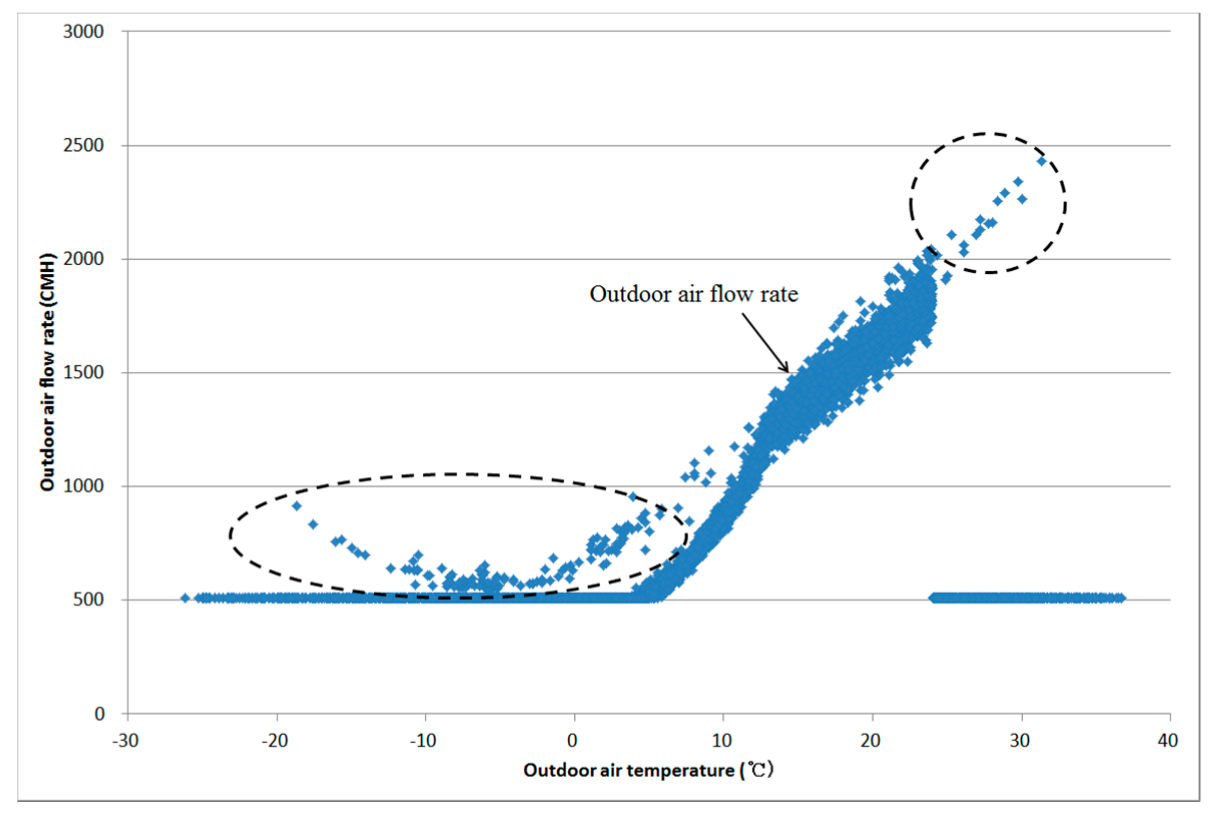
Figure 6 shows the relationship between outdoor air and outdoor air flow rate by simulation using the CO2 integration control method. Minimum outdoor air alone was inhaled and the economizer was operated in other sections when the indoor temperature exceeded a set temperature (24 °C) and outdoor temperature was 5 °C or lower in the case of the existing outdoor air flow rate control. However, when applying CO2 integration control method, outdoor air was inhaled more than the minimum outdoor air flow rate even in the minimum outdoor air flow rate section to control the indoor CO2 concentration. The more outdoor air inhaled, the more energy will be consumed in the AHU and the reheating coil. However, the control of the indoor CO2 concentration is considered to require an increase in the outdoor air flow rate.
Calculated with the air flow rate increase method, the air flow rate is greater than that to eliminate indoor load and may consume too much air conditioning and heating energy without controlling the indoor temperature. To solve this problem, this study proposed a VAV terminal unit CO2 integration control method that resets the outdoor air flow rate and supply temperature on the basis of the above-mentioned air flow rate increase method. When increasing the air flow rate to control CO2 concentration, the air flow rate supplied is more than required and air conditioning and heating energy is wasted. Therefore, when a VAV terminal unit system works in a ventilation mode due to the non-control of CO2 concentration, the supply temperature should be reset using Equations (9) and (10) to ensure that set indoor temperature is maintained:
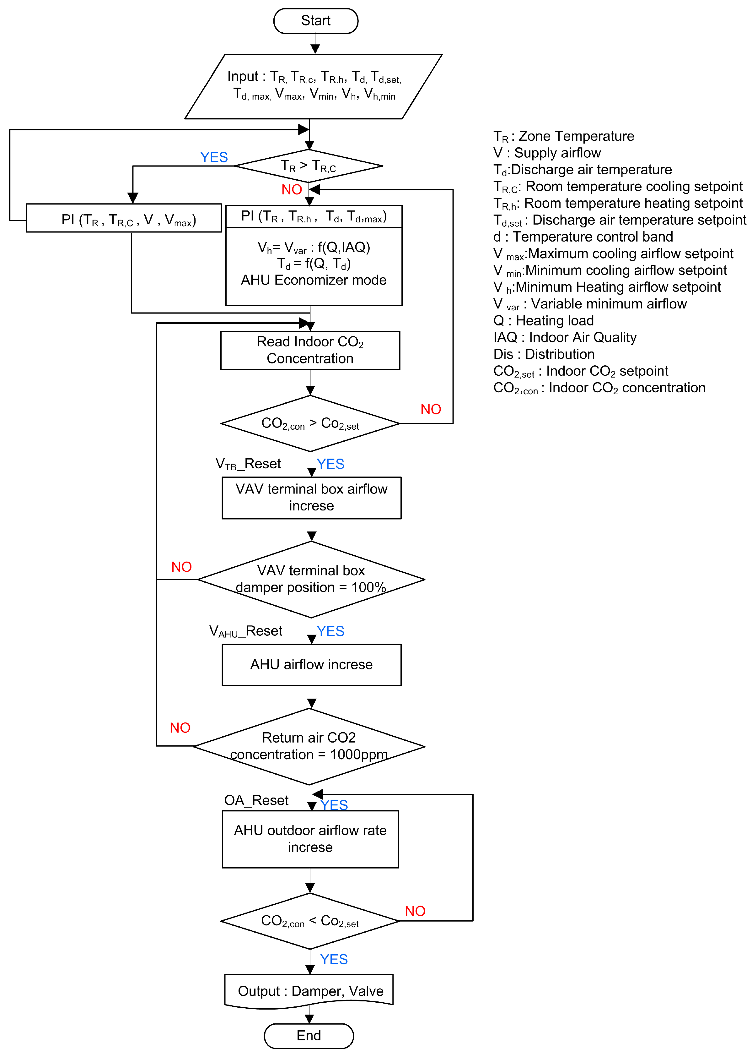
Figure 7 shows a VAV system CO2 integration control algorithm.
(1) Cooling Mode
Cooling mode begins when the indoor temperature is higher than the indoor cooling set temperature. Air flow rate is determined by the cooling load, and a damper is operated to maintain a set indoor temperature between the maximum and minimum air flow rates.
(2) Heating Mode
Heating mode begins when the indoor temperature is lower than the indoor heating set temperature. Air flow rate is determined by the heating load and minimum outdoor air flow rate, and the reheating coil has a valve operated to maintain an air supply set temperature.
(3) Ventilation Mode
When the indoor CO2 concentration is higher than 1000 ppm, an increase occurs in the air flow rates in the terminal unit and the AHU. The air flow rate of the terminal unit increases by 10% of the maximum air flow rate, and the air flow rate of the AHU is increased by 10%, when the damper opening ratio of terminal unit is 100% and indoor CO2 concentration is higher than 1000 ppm. When the supply CO2 concentration exceeds 1000 ppm, an increase in the outdoor air flow rate occurs. When operating a ventilation mode, the air supply set temperature of the reheating coil is reset according to Equation (10). When the ventilation mode is finished, a heating mode is followed by the air supply set temperature of the reheating coil.
4. Results and Discussion
The indoor thermal comfort, IAQ, and stratification issue were estimated to evaluate the proposed control method of the VAV terminal unit. An analysis of the indoor thermal comfort was conducted using the standards of the indoor set temperature (24 °C).
An evaluation of the IAQ was conducted based on the indoor CO2 concentration. The standard of the indoor CO2 concentration was 1000 ppm. Stratification was considered to have occurred when the temperature difference between 0.1 m and 1.1 m from the floor was more than 3 °C [26].
4.1. Indoor Environment Comfort
4.1.1. Indoor Temperature
Figure 8 shows the indoor temperatures in the case of peak load in summer and winter in the proposed VAV terminal unit control method. In every zone, indoor temperatures are 23–25 °C, which meets the 24 ± 1 °C indoor set temperature.
4.1.2. Indoor CO2 Concentration
Figure 9a shows an indoor CO2 concentration in the case of peak load in winter in the proposed VAV terminal unit control algorithm. Indoor CO2 concentration remained at 1000 ppm or lower under most conditions, which meets the IAQ standards. In Zone 2, there appeared a section in which CO2 concentration exceeded 1000 ppm due to an increase in the number of occupants. However, indoor CO2 concentration is kept the same as, or below, the standard value with the operation of the ventilation mode according to the proposed VAV terminal unit control method. Figure 9b shows an indoor CO2 concentration in the case of peak load in summer. Indoor CO2 concentration was kept at 1000 ppm, or lower, under most conditions. In Zone 2, there appeared a section in which CO2 concentration exceeded 1000 ppm with an increase in the number of occupants. However, the proposed VAV terminal unit control increased the air flow rate or outdoor air flow rate, thus keeping the indoor CO2 concentration below the standard value. Indoor CO2 concentration was higher in winter than in summer. If outdoor air temperature falls below a specific temperature with the operation of the economizer, the AHU minimizes the outdoor air flow rate, thus increasing the indoor CO2 concentration in winter. If the outdoor air temperature rises above a specific temperature, the AHU minimizes the outdoor air flow rate, but indoor CO2 concentration is considered to be kept low due to the high air flow rate at the terminal unit.
4.1.3. Indoor Vertical Temperature Difference
Stratification was considered to have occurred when the temperature difference between 0.1 m and 1.1 m from the floor was more than 3 °C. “To analyze the stratification, the space was separated into 17 horizontal nodes with 0.2 m intervals from the bottom. This divided the internal heating elements among each horizontal node” [16]. Figure 10 shows the indoor vertical temperature difference in the proposed control algorithm at the peak load in winter. The proposed algorithm satisfied the indoor set temperature without stratification in any zone.
4.2. Energy Consumption
The VAV terminal unit control method of the existing case is a fixed minimum air flow rate control. The minimum air flow rate is 30% of the maximum air flow rate. As the existing terminal unit minimum air flow rate is set at a fixed value, the fixed air flow rate is supplied even in the case of low indoor load and causes the unnecessary consumption of fan and reheating energy, which leads to an increase in total energy consumption. Accordingly, this study proposed a control method for making the minimum air flow rate float according to the load and stabilizing the IAQ even in the case of sudden load change. The method satisfied both the indoor thermal comfort and the IAQ. By analyzing energy consumption, this chapter evaluated the VAV terminal unit control method and the CO2 integration control method to which the existing fixed minimum air flow rate was applied. Energy analysis of the existing VAV terminal unit control method and the proposed control method presented in this chapter was conducted. Table 7 shows the simulation case.
Figure 11 shows AHU component-specific energy consumption by case. Reheating coil energy was approximately 10.4 GJ and 8.3 GJ in the existing control method Case 1 and the proposed control method Case 2, respectively: energy consumption decreased by approximately 20% in Case 2, as compared to Case 1. In the cooling coil, energy was approximately 82,000 MJ and 69 GJ in Case 1 and Case 2, respectively: energy decreased by approximately 15% in Case 2, as compared to Case 1. In the supply fan, energy was approximately 17 GJ and 15 GJ in Case 1 and Case 2, respectively: energy decreased by approximately 15% in Case 2, as compared to Case 1. Total energy consumption decreased by approximately 17 GJ, 16% at the AHU, including the reheat and cooling coils and the supply fan.
Figure 12 compares the reheating coil energy consumption of each zone. Annual reheating coil energy consumption was reduced at least 34%, and up to 94%. This result was caused by the resetting of the minimum air flow rate and supply temperature. The supplied air flow rate of each zone was decreased by applying a floating minimum air flow rate and energy was saved by resetting the supply air temperature lower than the fixed temperature.
Figure 13 compares energy consumption, including those of the AHU and reheating coil. The total energy consumption at the reheating coil of the terminal unit showed approximately 118 GJ, according to the existing terminal unit control method, but decreased by approximately 68% according to the proposed terminal unit control method. This result was caused by the resetting of the minimum air flow rate and supply temperature. The supplied air flow rate of each zone was decreased by the application of a floating minimum air flow rate, and energy was saved by lowering the supply temperature below the fixed temperature. Total energy consumption was approximately 228 GJ and 135 GJ at Case 1 and Case 2, respectively. Energy consumption was decreased by approximately 41% by the proposed terminal unit control method, as compared to the existing one.
5. Conclusions
The minimum air flow rate of the VAV terminal unit is a chief factor that has a direct influence on indoor heat comfort, IAQ, and energy consumption. This makes it very important to select an optimal minimum air flow rate. According to the existing VAV terminal unit control, indoor temperature, alone, is controlled using a fixed minimum air flow rate, and IAQ can be affected by the change in the number of occupants. Therefore, this study proposed a VAV terminal unit control method considering an indoor ventilation requirement in a multi-zone, and evaluated a terminal unit control method proposed in comparison with the existing one.
- (1)
- The target space selected eight zones that are controlled using an AHU and applied the fixed minimum air flow rate of the VAV terminal unit. The simulation results showed that the indoor set temperature was maintained. However, when the number of occupants increased suddenly, only the indoor temperature was checked and controlled according to the existing terminal unit control method, which created IAQ problems. To solve the problem of the existing terminal unit control method, the present study proposed a terminal unit control method by the application of a variable minimum air flow rate and the increase in the terminal unit air flow rate, AHU air flow rate, and outdoor air flow rate.
- (2)
- IAQ control was improved by the terminal unit and AHU air flow rate increase method, as compared to the existing control method. However, when the outdoor air flow rate was low in winter, the IAQ was not maintained even by the supplied maximum air flow rate of the terminal unit. When the IAQ was not controlled, even at the maximum air flow rate of the terminal unit, the air flow rate was supplied, with its CO2 concentration lowered by the increase in the air flow rate of the AHU. This increased the air flow rate in zones with stable indoor thermal comfort and air quality, thus exceeding the set indoor temperature.
- (3)
- This study proposed a VAV terminal unit CO2 integration control method for increasing the outdoor air flow rate according to the increase in air flow rate at the terminal unit and AHU on the basis of indoor CO2 concentration. Any CO2 problem led to the operation of the ventilation mode, which increased the air flow rate and solved the IAQ. Indoor thermal comfort was also stable, even when the air flow rate was increased with the resetting of the supply temperature by the increase in the air flow rate. The proposed VAV terminal unit control method satisfies all the conditions of indoor thermal comfort, IAQ, and stratification. An energy comparison with the existing control method showed that the method not only satisfies the indoor thermal comfort, IAQ, and stratification, but also reduces energy consumption.
Acknowledgments
This research was supported by a grant (17 CTAP-C115251-02) from the Technology Advancement Research Program (TARP) funded by the Ministry of Land, Infrastructure, and Transport of the Korean government.
Author Contributions
All authors contributed to this work. Hyo-Jun Kim performed the results analysis and wrote the majority of this article. Young-Hum Cho was responsible for this article and gave conceptual advice.
Conflicts of Interest
The authors declare no conflict of interest.
Nomenclature
| Room heating road, kw | |
| Standard air density, kg/m3 | |
| Specific heat capacity, kj/kg °C | |
| Supply air temperature, °C | |
| Room air temperature, °C | |
| Minimum air flow rate for ventilation, m3/h | |
| Air flow rate for heating load, m3/h | |
| Outdoor airflow rate required per person from ASHRAE Standard 62.1–2010 m3/h∙person | |
| Zoon population, person | |
| Outdoor airflow rate required per unit area from ASHRAE Standard 62.1–2010 m3/h∙m2 | |
| Zoon floor area, m2 | |
| Critical zone outdoor air flow rate ratio | |
| Uncorrected AHU outdoor air flow rate ratio | |
| Air flow rate for outdoor air (ventilation) requirement of AHU, m3/h | |
| Supply air flow rate for each zone, m3/h | |
| Corrected AHU outdoor air flow rate ratio | |
| Minimum air flow rate, m3/h |
References
- Hurnik, M. Novel cylindrical induction controller and its application in VAV air conditioning system in an office building. Energy Build. 2016, 130, 341–349. [Google Scholar] [CrossRef]
- Wang, G.; Song, L. Air handling unit supply air temperature optimal control during economizer cycles. Energy Build. 2012, 49, 310–316. [Google Scholar] [CrossRef]
- Yao, Y.; Wang, L. Energy analysis on VAV system with different air-side economizers in China. Energy Build. 2010, 42, 1220–1230. [Google Scholar] [CrossRef]
- Okochi, G.; Yao, Y. A review of recent developments and technological advancements of variable-air-volume (VAV) air-conditioning systems. Renew. Sustain. Energy Rev. 2016, 59, 784–817. [Google Scholar] [CrossRef]
- Yao, Y.; Lian, Z.; Liu, W.; Hou, Z.; Wu, M. Evaluation program for the energy-saving of variable-air-volume systems. Energy Build. 2007, 39, 558–568. [Google Scholar] [CrossRef]
- Engdahl, F.; Johansson, D. Optimal supply air temperature with respect to energy use in a variable air volume system. Energy Build. 2004, 36, 205–218. [Google Scholar] [CrossRef]
- Congradac, V.; Kulic, F. HVAC system optimization with CO2 concentrationcontrol using genetic algorithms. Energy Build. 2009, 41, 571–577. [Google Scholar] [CrossRef]
- Nassif, N.; Moujaes, S. A new operating strategy for economizer dampers of VAV system. Energy Build. 2008, 40, 289–299. [Google Scholar] [CrossRef]
- Cho, Y.-H.; Liu, M. Single-duct constant volume system optimization. Energy Build. 2009, 41, 856–862. [Google Scholar] [CrossRef]
- Cho, Y.-H.; Liu, M. Minimum airflow reset of single duct VAV terminal boxes. Build. Environ. 2009, 44, 1876–1885. [Google Scholar] [CrossRef]
- Houghton, D. Demand-Controlled Ventilation: Teaching Buildings to Breathe; E-Source, Inc.: Boulder, CO, USA, 1995. [Google Scholar]
- Pavlovas, V. Demand controlled ventilation a case study for existing Swedish multifamily buildings. Energy Build. 2004, 36, 1029–1034. [Google Scholar] [CrossRef]
- Lu, T.; Lü, X.; Viljanen, M. A novel and dynamic demand-controlled ventilation strategy for CO2 control and energy saving in buildings. Energy Build. 2011, 43, 2499–2508. [Google Scholar] [CrossRef]
- Mysen, M.; Berntsen, S.; Nafstad, P.; Schild, P.G. Occupancy density and benefits of demand-controlled ventilation in Norwegian primary schools. Energy Build. 2005, 37, 1234–1240. [Google Scholar] [CrossRef]
- Cho, Y.; Liu, M. Correlation between minimum airflow and discharge air temperature. Build. Environ. 2010, 45, 1601–1611. [Google Scholar] [CrossRef]
- Kang, S.; Kim, H.; Cho, Y. A Study on the control method of single duct VAV terminal unit through the determination of proper minimum air flow. Energy Build. 2014, 69, 464–472. [Google Scholar] [CrossRef]
- Kim, H.; Kang, S.; Cho, Y. A study on the control method without stratification of single duct VAV terminal units. J. Asian Archit. Build. Eng. 2015, 14, 467–474. [Google Scholar] [CrossRef]
- American Society of Heating, Refrigerating and Air-Conditioning Engineers (ASHRAE). Design and Application of Controls; ASHEAE: Atlanta, GA, USA, 2004. [Google Scholar]
- California Energy Commission (CEC). Building Energy Efficiency Standards for Residential and Non-Residential Buildings; California Code of Regulations Title 24, Part 1; CEC.400.2008.001.CMF; California Energy Commission: Sacramento, CA, USA, 2008.
- American Society of Heating, Refrigerating and Air-Conditioning Engineers (ASHRAE). ASHRAE Standard 90.1-2010: Energy Standard for Buildings Except Low-Rise Residential Buildings; ASHEAE: Atlanta, GA, USA, 2010. [Google Scholar]
- American Society of Heating, Refrigerating and Air-Conditioning Engineers (ASHRAE). ASHRAE Standard 62.1-2010: Ventilation for Acceptable Indoor Air Quality (IAQ); ASHEAE: Atlanta, GA, USA, 2010. [Google Scholar]
- Jin, X.; Ren, H.; Xiao, X. Prediction-based online optimal control of outdoor air of multi-zone VAV air conditioning systems. Energy Build. 2005, 37, 939–944. [Google Scholar] [CrossRef]
- Du, Z.; Jin, X.; Yang, X. A robot fault diagnostic tool for flow rate sensors in air dampers and VAV terminals. Energy Build. 2009, 41, 279–286. [Google Scholar] [CrossRef]
- Cho, Y. Development of a Terminal Control System with Variable Minimum Airflow Rate. Energies 2012, 5, 4643–4664. [Google Scholar] [CrossRef]
- TRNSYS 17—Volume 5. Multi Zone Building Modeling with Type 56 and TRNBuild; Thermal Energy System Specialists: Madison, WI, USA, 2010.
- American Society of Heating, Refrigerating and Air-Conditioning Engineers (ASHRAE). ASHRAE Standard 55-2010: Thermal Environmental Conditions for Human Occupancy; ASHEAE: Atlanta, GA, USA, 2010. [Google Scholar]
Figure 1.
Control sequence of the VAV terminal units (from the ASHRAE Application Handbook, Ch. 45 [18]).
Figure 1.
Control sequence of the VAV terminal units (from the ASHRAE Application Handbook, Ch. 45 [18]).
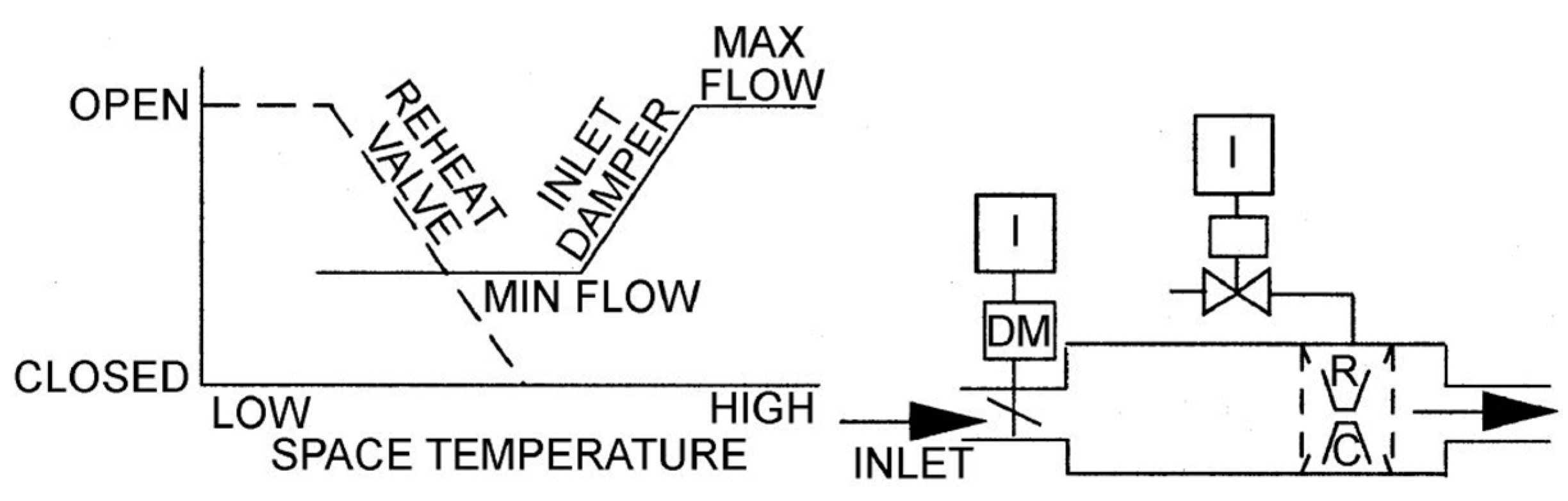
Figure 2.
Schematic diagram of a single-duct VAV system and terminal unit.
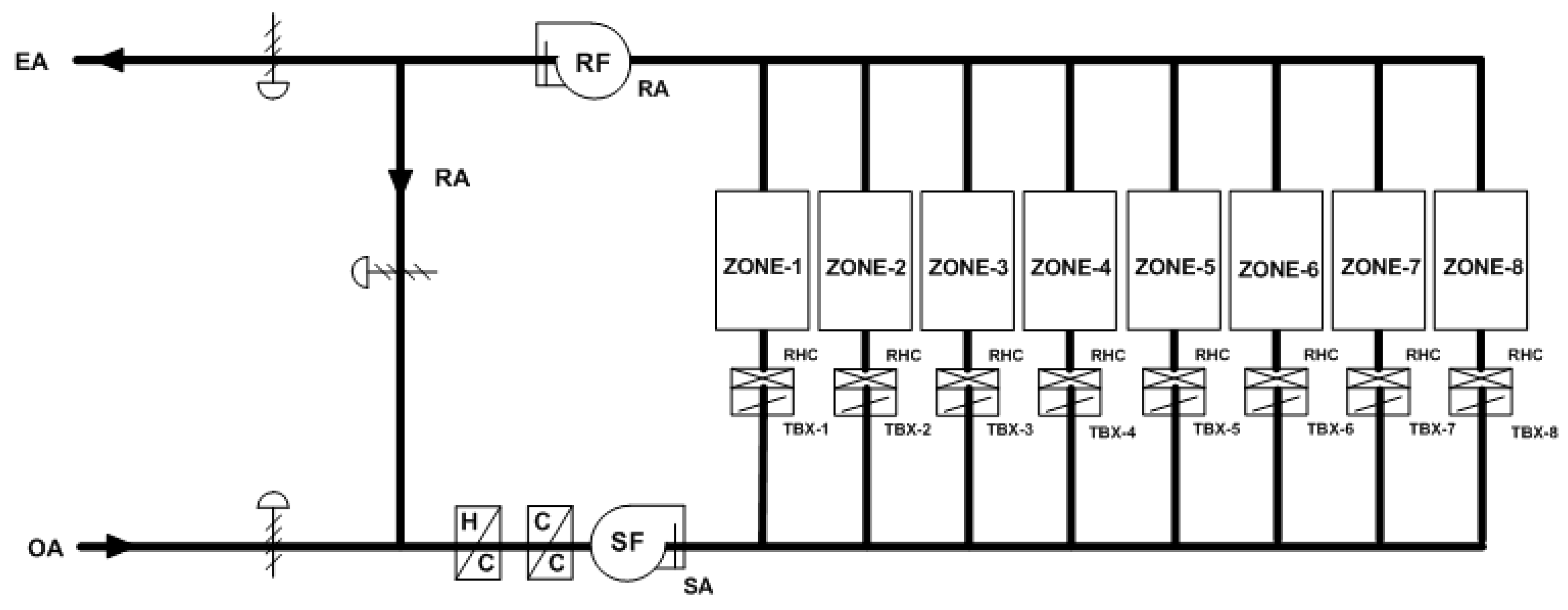
Figure 3.
Load schedule: (a) working days; and (b) weekends.
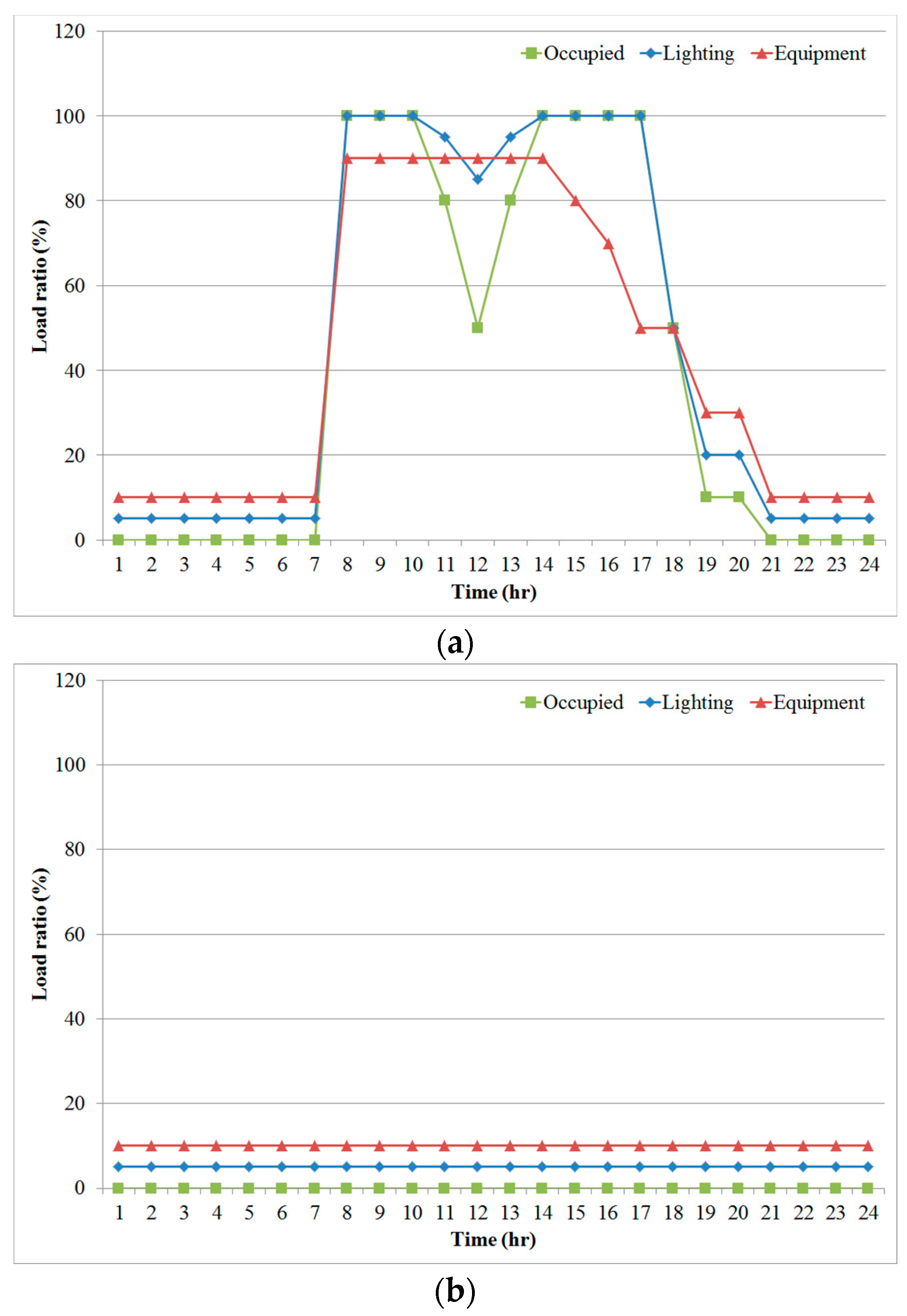
Figure 4.
Existing control method algorithm of the VAV terminal unit.
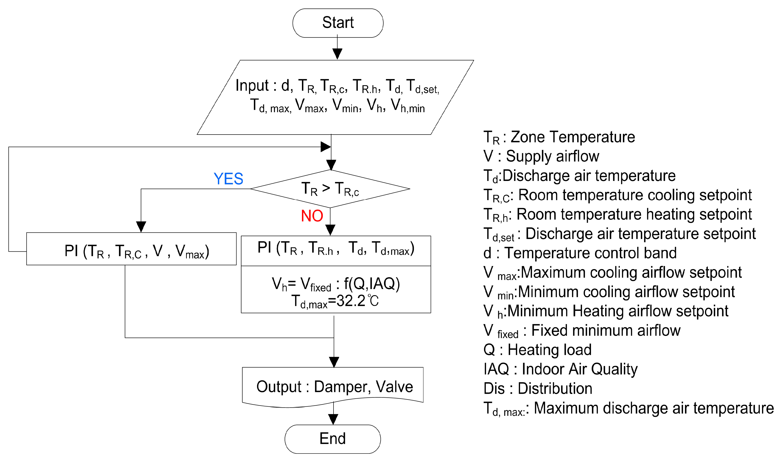
Figure 5.
Simulation result using existing control method of the VAV terminal unit in winter.
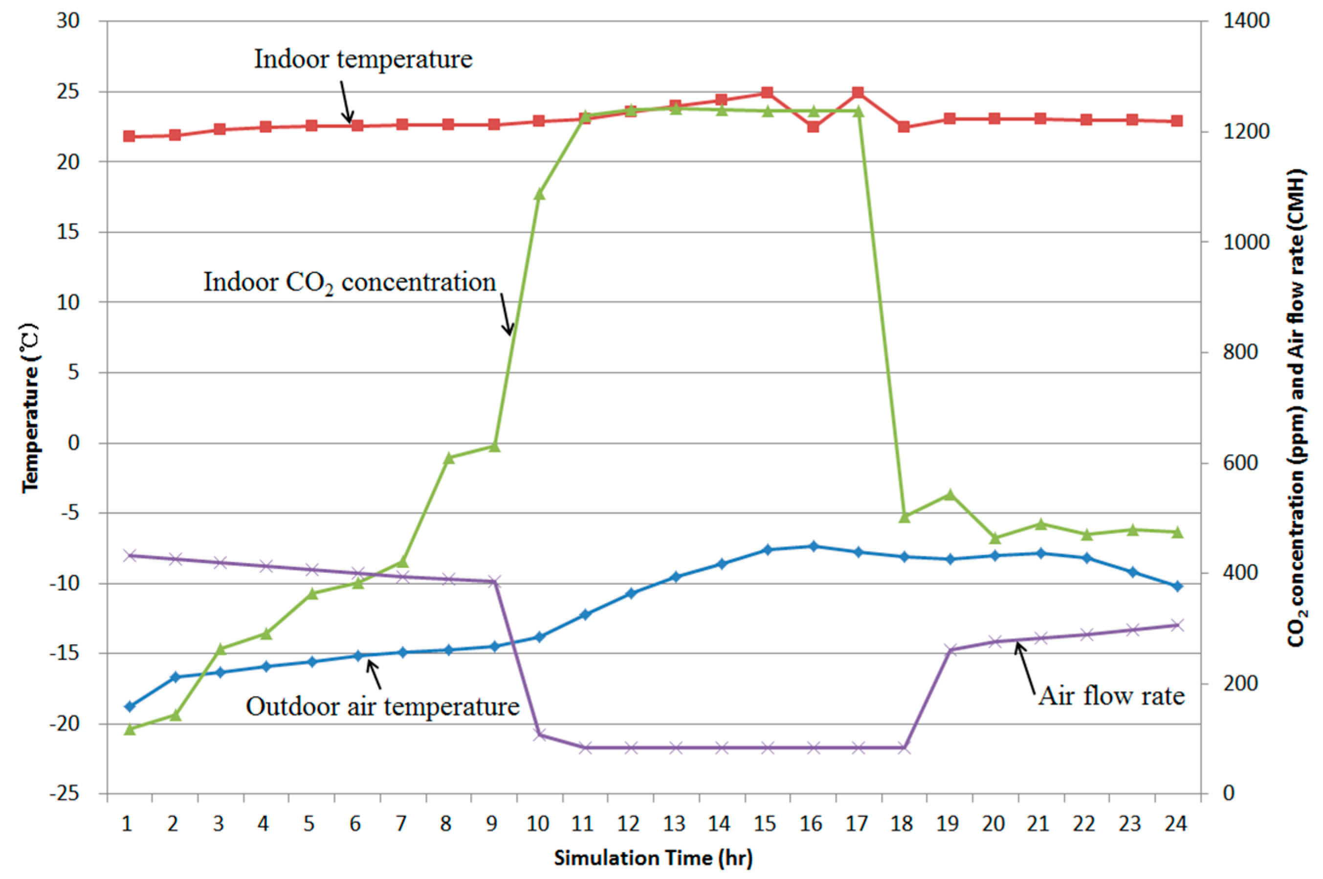
Figure 6.
Relationship between outdoor climate and outdoor air flow rate by resetting of the outdoor air flow rate.
Figure 6.
Relationship between outdoor climate and outdoor air flow rate by resetting of the outdoor air flow rate.

Figure 7.
VAV system CO2 integration control algorithm.

Figure 8.
Thermal comfort analysis data of the proposed control method.
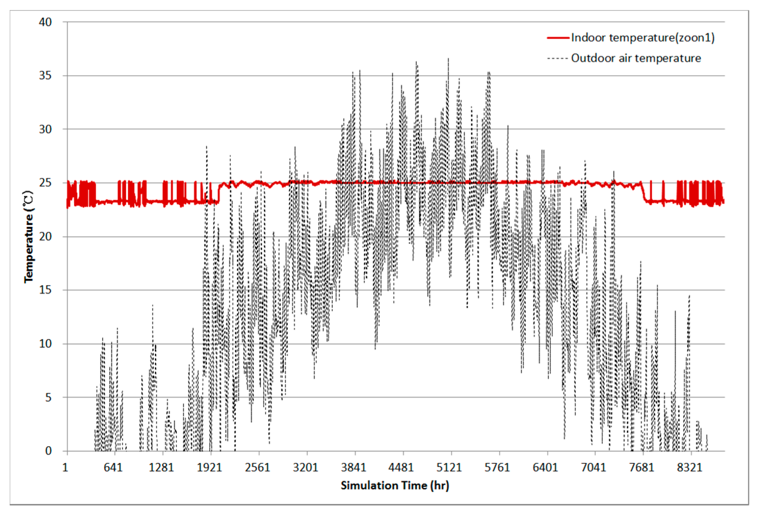
Figure 9.
Indoor CO2 concentration analysis data of the proposed control method: (a) winter; and (b) summer.
Figure 9.
Indoor CO2 concentration analysis data of the proposed control method: (a) winter; and (b) summer.
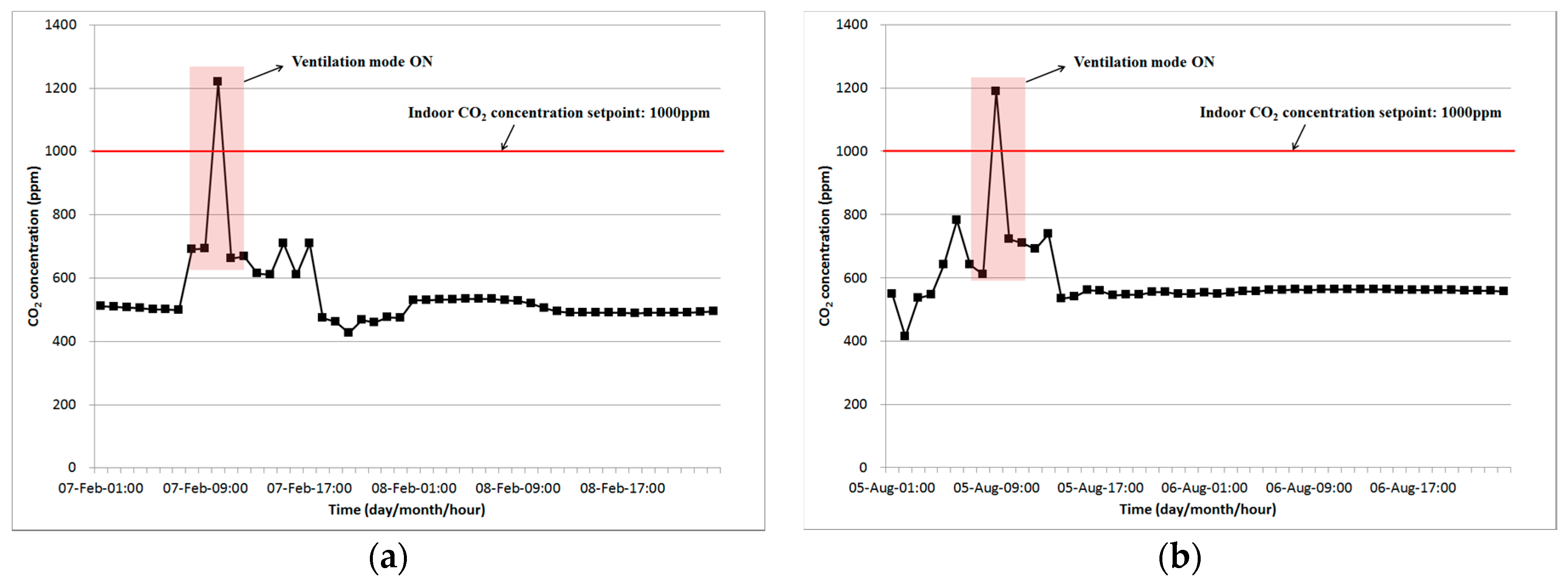
Figure 10.
Vertical room air temperature data of the proposed control method.
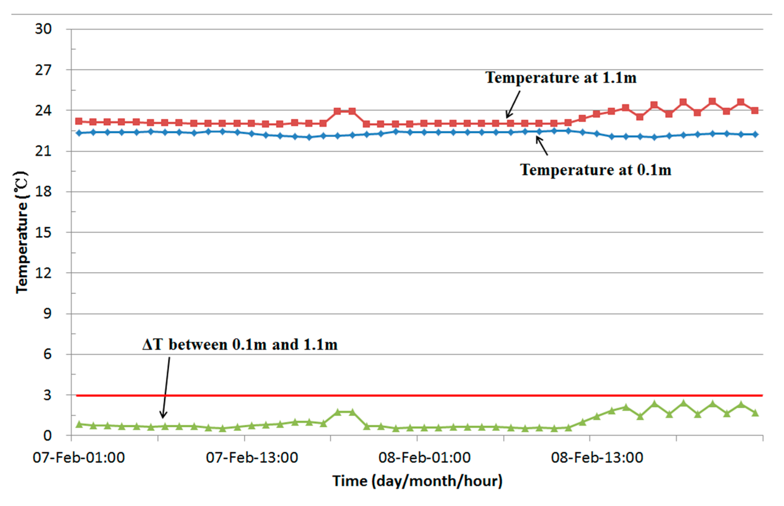
Figure 11.
Comparison of the AHU energy consumption between the existing and proposed control methods.
Figure 11.
Comparison of the AHU energy consumption between the existing and proposed control methods.
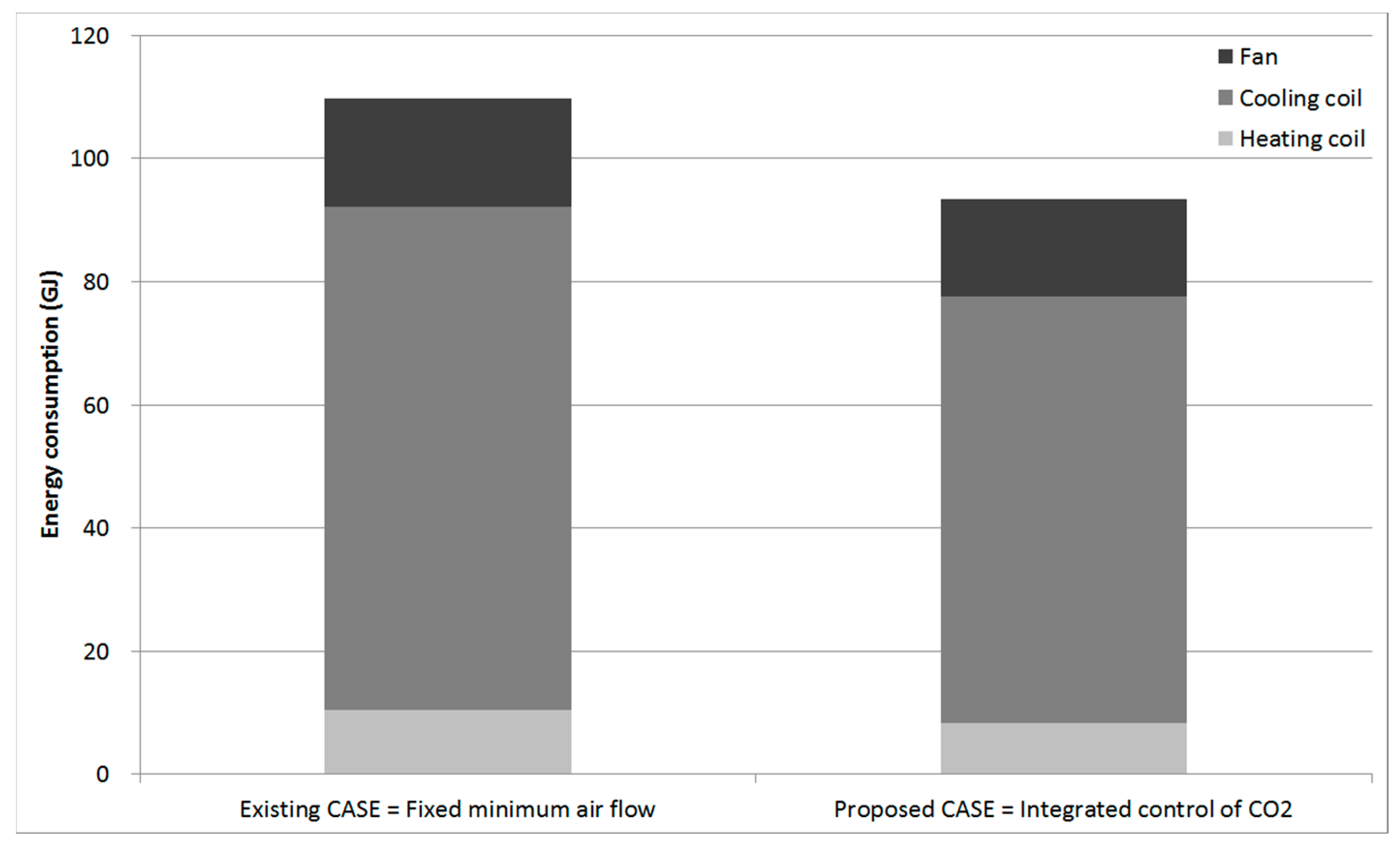
Figure 12.
Comparison of the reheating coil energy consumption between the existing and proposed control methods.
Figure 12.
Comparison of the reheating coil energy consumption between the existing and proposed control methods.
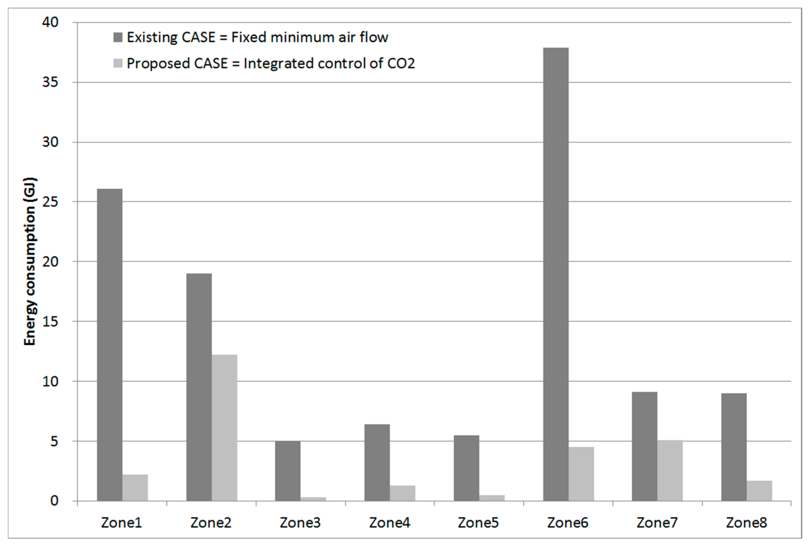
Figure 13.
Comparison of the total energy consumption between the existing case and the proposed case.
Figure 13.
Comparison of the total energy consumption between the existing case and the proposed case.


Table 1.
Minimum ventilation rates in office building (from ASHRAE Standard 62.1 [21]).
Table 1.
Minimum ventilation rates in office building (from ASHRAE Standard 62.1 [21]).
| Occupancy Category | People Outdoor Air Rate | Area Outdoor Air Rate | Default Values | ||
|---|---|---|---|---|---|
| Occupant Density | Combined Outdoor Air Rate | ||||
| m3/h Person | m3/h m2 | #/100 m2 | m3/h Person | ||
| Office Building | Break rooms | 2.5 | 0.6 | 50 | 3.5 |
| Office space | 2.5 | 0.3 | 5 | 8.5 | |
| Reception areas | 2.5 | 0.3 | 30 | 3.5 | |
| Main lobbies | 2.5 | 0.3 | 10 | 5.5 | |
Table 2.
Simulation conditions.
| Lists | Contents | ||
|---|---|---|---|
| Buildings | Location | Lincoln, NE, USA | |
| Use | Office | ||
| System | AHUs | Type | Single duct VAV system |
| Design air flow rate | 2420 m3/h | ||
| Design Supply fam power | 15 kW | ||
| VAV Terminal unit | VAV terminal unit with reheat system | ||
| Operating conditions | Schedule | 24 h | |
| Set point temperature | 24 °C | ||
| Load conditions | Occupant [25] | Seated, Light work, typing 150 W/person | |
| Light | 13 W/m2 | ||
| Equipment | 16 W/m2 | ||
| Material properties | Exterior wall | Thickness | 0.2 m |
| Thermal transmittance | 0.31 W/m2 K | ||
| Interior wall | Thickness | 0.09 m | |
| Thermal transmittance | 0.508 W/m2 K | ||
| Floor | Thickness | 0.3 m | |
| Thermal transmittance | 0.039 W/m2 K | ||
| roof | Thickness | 0.141 m | |
| Thermal transmittance | 0.316 W/m2 K | ||
Table 3.
Maximum and minimum air flow rates of a VAV terminal unit.
| Zone | Type | Maximum Air Flow Rate | Minimum Air Flow Rate |
|---|---|---|---|
| m3/h | m3/h | ||
| Zone 1 | VAV Terminal unit with reheating coil | 600 | 166 |
| Zone 2 | 350 | 92 | |
| Zone 3 | 160 | 37 | |
| Zone 4 | 190 | 42 | |
| Zone 5 | 178 | 38 | |
| Zone 6 | 890 | 252 | |
| Zone 7 | 220 | 50 | |
| Zone 8 | 210 | 47 |
Table 4.
Outdoor air flow rate for ventilation (ASHRAE Standard 62.1).
| Zone | People Outdoor Air Rate | Occupants | Area Outdoor Air Rate | Floor Area | Zone Air Distribution Effectiveness | Outdoor Air Flow Rate |
|---|---|---|---|---|---|---|
| m3/h·Person | Person | m3/h·m2 | m2 | - | m3/h | |
| Zone 1 | 9 | 4 | 1.08 | 28 | 0.8 | 108 |
| Zone 2 | 9 | 8 | 1.08 | 14 | 0.8 | 141 |
| Zone 3 | 9 | 1 | 1.08 | 4.2 | 0.8 | 22 |
| Zone 4 | 9 | 1 | 1.08 | 7.56 | 0.8 | 28 |
| Zone 5 | 9 | 1 | 1.08 | 4.68 | 0.8 | 23 |
| Zone 6 | 9 | 6 | 1.08 | 49.36 | 0.8 | 174 |
| Zone 7 | 9 | 1 | 1.08 | 8.96 | 0.8 | 30 |
| Zone 8 | 9 | 1 | 1.08 | 6.48 | 0.8 | 26 |
| AHU | 552 |
Table 5.
Determined outdoor air flow rate using ASHRAE Standard 62.1.
| Zone 1 | Zone 2 | Zone 3 | Zone 4 | Zone 5 | Zone 6 | Zone 7 | Zone 8 | Total | |
|---|---|---|---|---|---|---|---|---|---|
| Supply air flow rate (m3/h) | 564 | 487 | 124 | 141 | 129 | 841 | 169 | 158 | 2613 |
| Outdoor air flow rate (m3/h) | 108 | 141 | 22 | 28 | 23 | 174 | 30 | 26 | 552 |
| Zi | 0.19 | 0.29 | 0.18 | 0.2 | 0.18 | 0.21 | 0.18 | 0.16 | - |
| X | 0.21 | ||||||||
| Z | 0.29 | ||||||||
| Y | 0.23 | ||||||||
| OA (m3/h) | 601 | ||||||||
Table 6.
Comparison of air flow rate between the existing and reset conditions.
| Zone | Existing Air Flow Rate | Air Flow Rate Reset | ||
|---|---|---|---|---|
| Maximum Air Flow Rate | Minimum Air Flow Rate | Maximum Air Flow Rate | Minimum Air Flow Rate | |
| m3/h | m3/h | m3/h | m3/h | |
| Zone 1 | 600 | 166 | 564 | 27~108 |
| Zone 2 | 350 | 92 | 487 | 21~84 |
| Zone 3 | 160 | 37 | 124 | 12~22 |
| Zone 4 | 190 | 42 | 141 | 10~28 |
| Zone 5 | 178 | 38 | 129 | 15~23 |
| Zone 6 | 890 | 252 | 841 | 80~174 |
| Zone 7 | 220 | 50 | 169 | 16~30 |
| Zone 8 | 210 | 47 | 158 | 11~26 |
Table 7.
Simulation case.
| Case | Control Logic | Classification |
|---|---|---|
| Existing case | Fixed minimum air flow rate | Existing control method of the VAV terminal unit in multi-zone |
| Constant minimum air flow setpoint: 30% of the maximum air flow rate | ||
| Proposed case | Variable minimum air flow rate | CO2 integration control method of the VAV system |
| Variable minimum air flow setpoint |
© 2017 by the authors. Licensee MDPI, Basel, Switzerland. This article is an open access article distributed under the terms and conditions of the Creative Commons Attribution (CC BY) license (http://creativecommons.org/licenses/by/4.0/).
Share and Cite
MDPI and ACS Style
Kim, H.-J.; Cho, Y.-H. A Study on a Control Method with a Ventilation Requirement of a VAV System in Multi-Zone. Sustainability 2017, 9, 2066. https://doi.org/10.3390/su9112066
AMA Style
Kim H-J, Cho Y-H. A Study on a Control Method with a Ventilation Requirement of a VAV System in Multi-Zone. Sustainability. 2017; 9(11):2066. https://doi.org/10.3390/su9112066
Chicago/Turabian StyleKim, Hyo-Jun, and Young-Hum Cho. 2017. "A Study on a Control Method with a Ventilation Requirement of a VAV System in Multi-Zone" Sustainability 9, no. 11: 2066. https://doi.org/10.3390/su9112066
Note that from the first issue of 2016, this journal uses article numbers instead of page numbers. See further details here.