
An Optimal Path Computation Architecture for the Cloud-Network on Software-Defined Networking


Abstract
:1. Introduction
1.1. Background
1.2. Research Objective
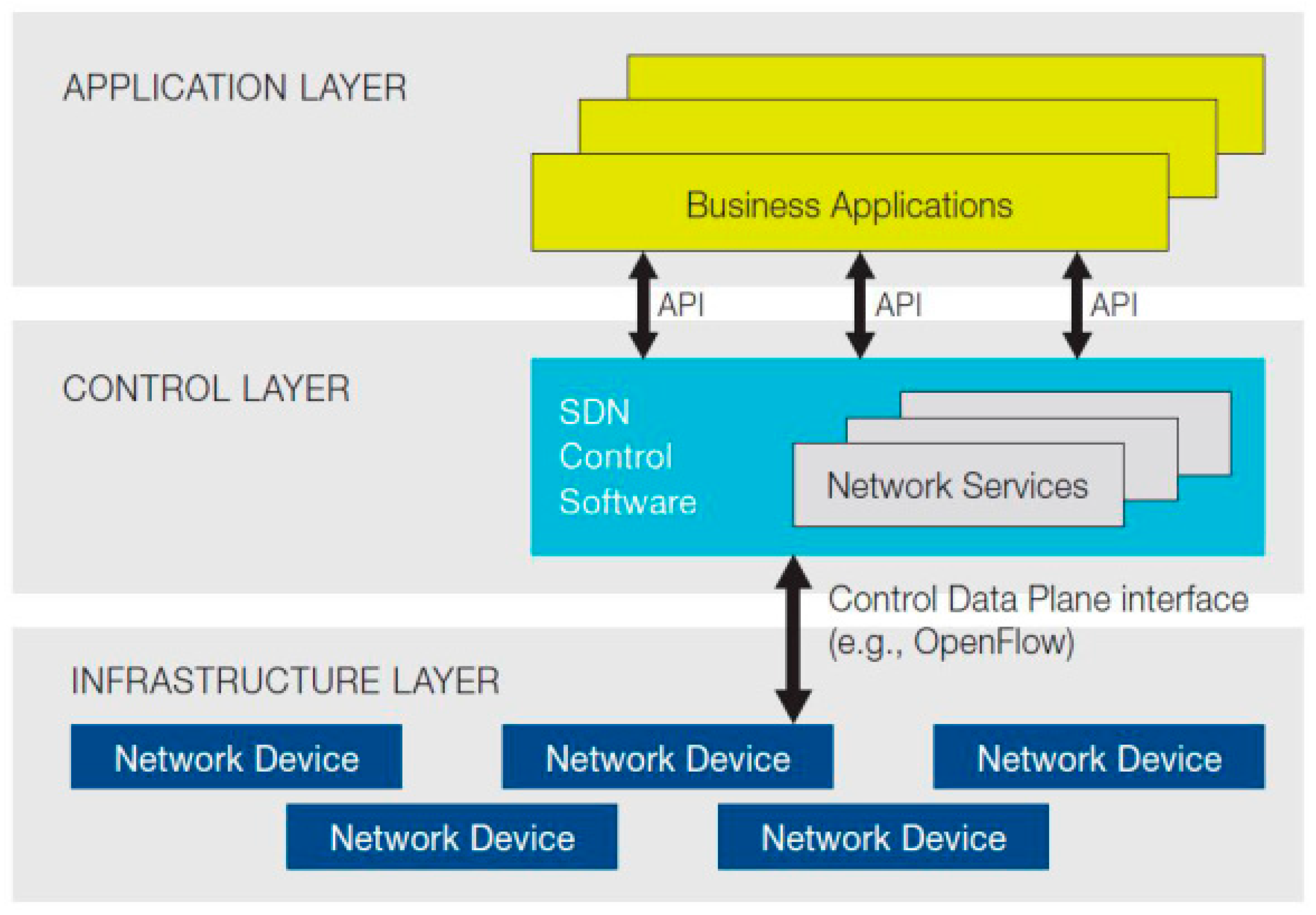
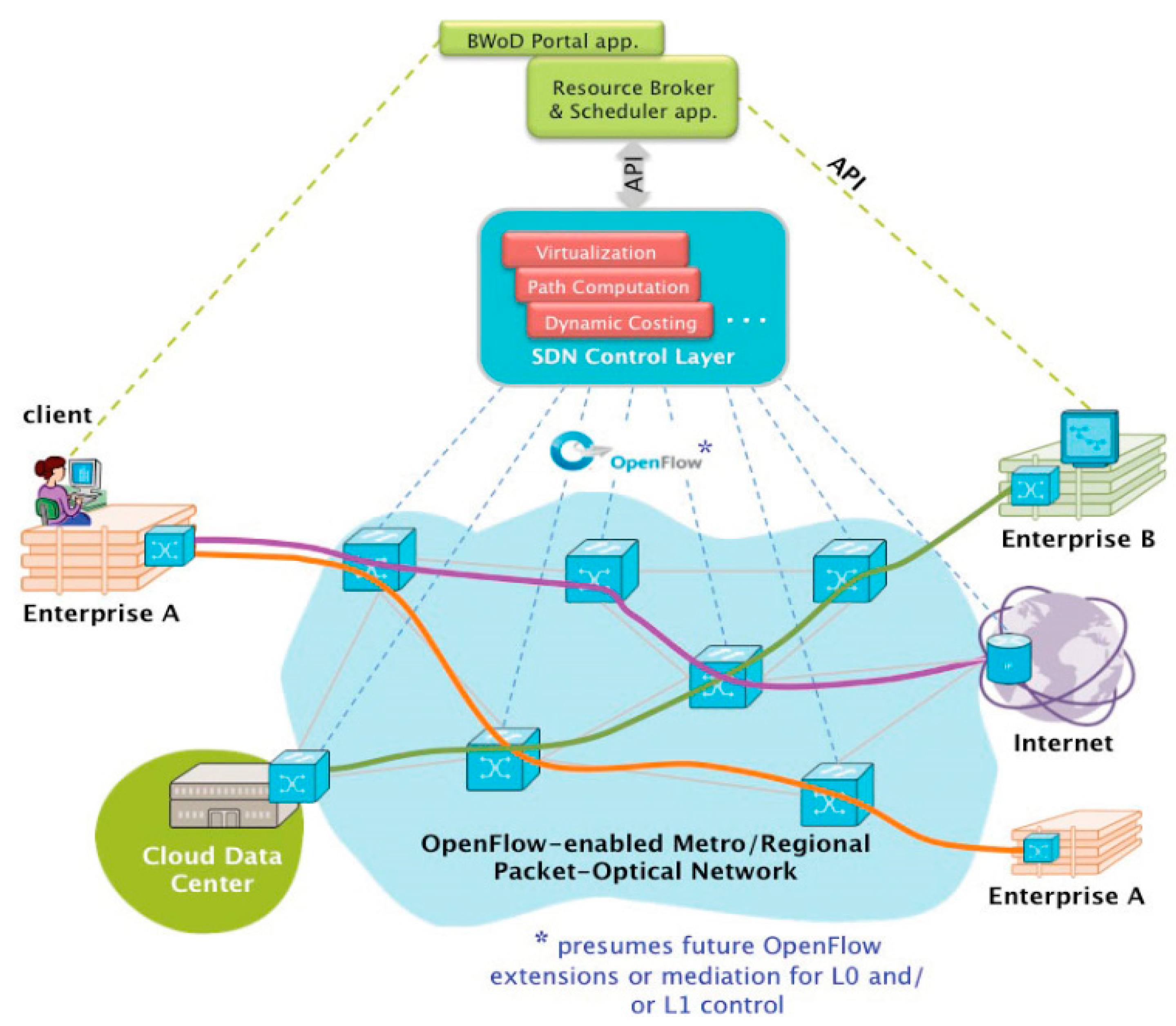
2. Software-Defined Networking

3. SDN-Based Path Management

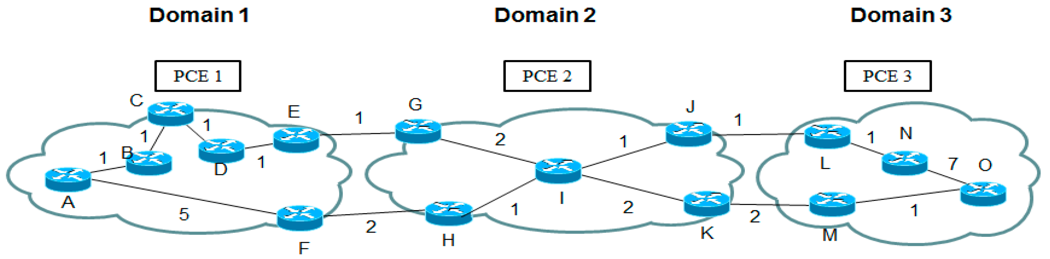
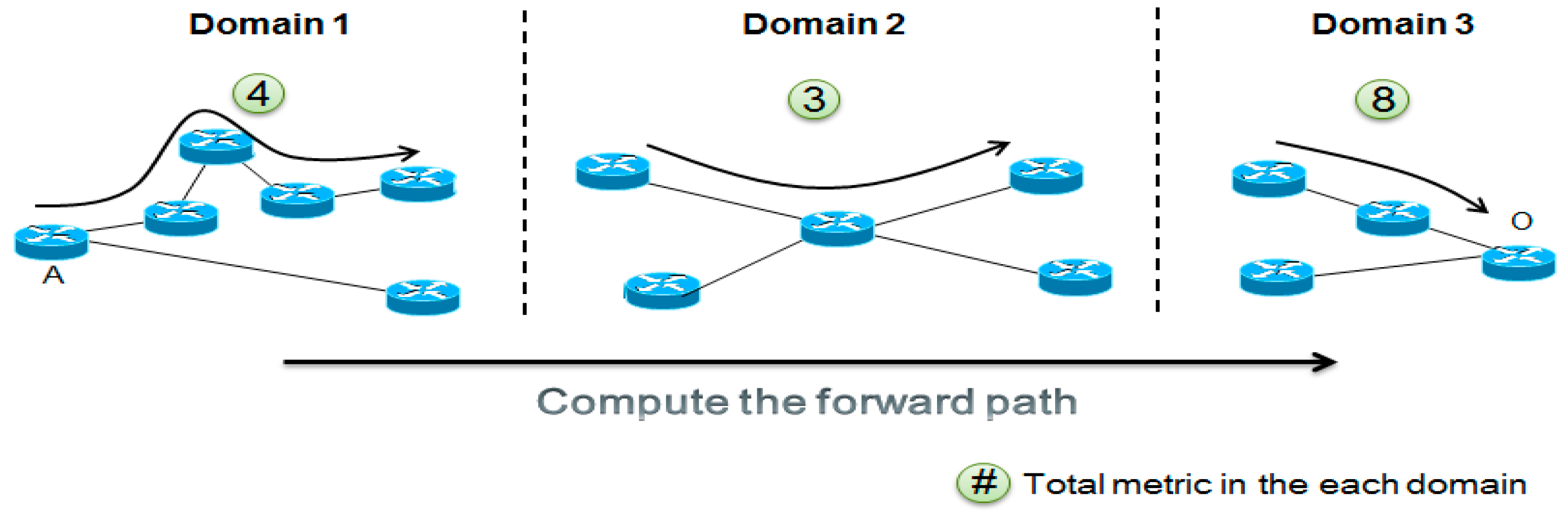
3.1. Per-Domain Path Computation
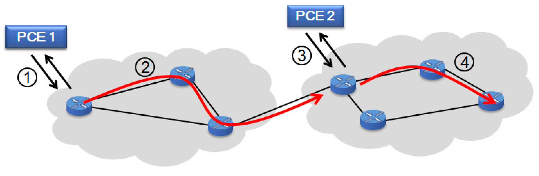
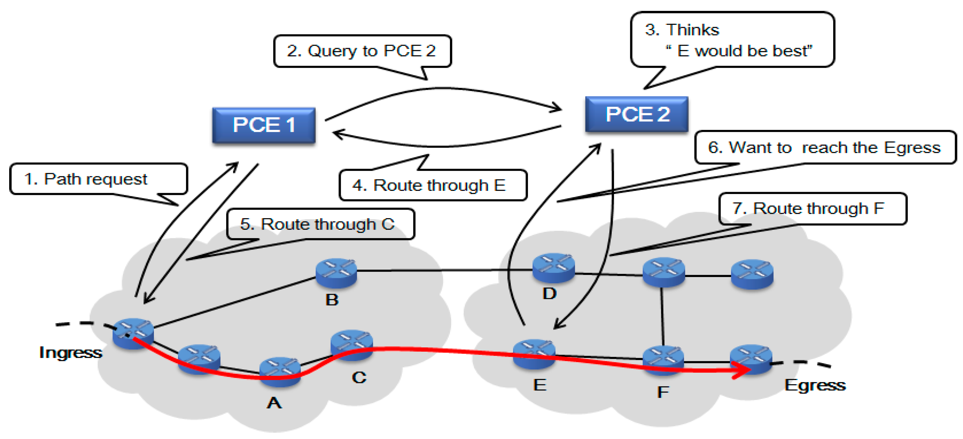
3.2. Simple Cooperating PCEs

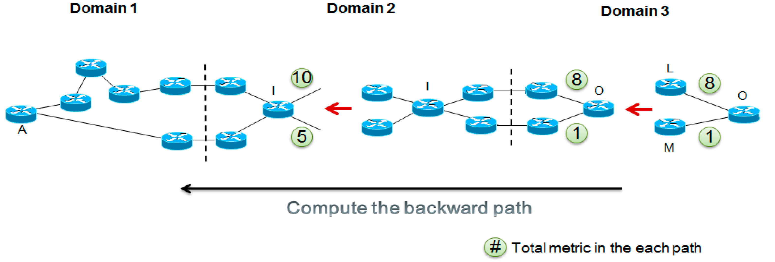
3.3. Backward Recursive Path Computation
4. SDN Routing Computation Application
4.1. SRC Model
4.1.1. Internal SRC Model
4.1.2. External SRC Model

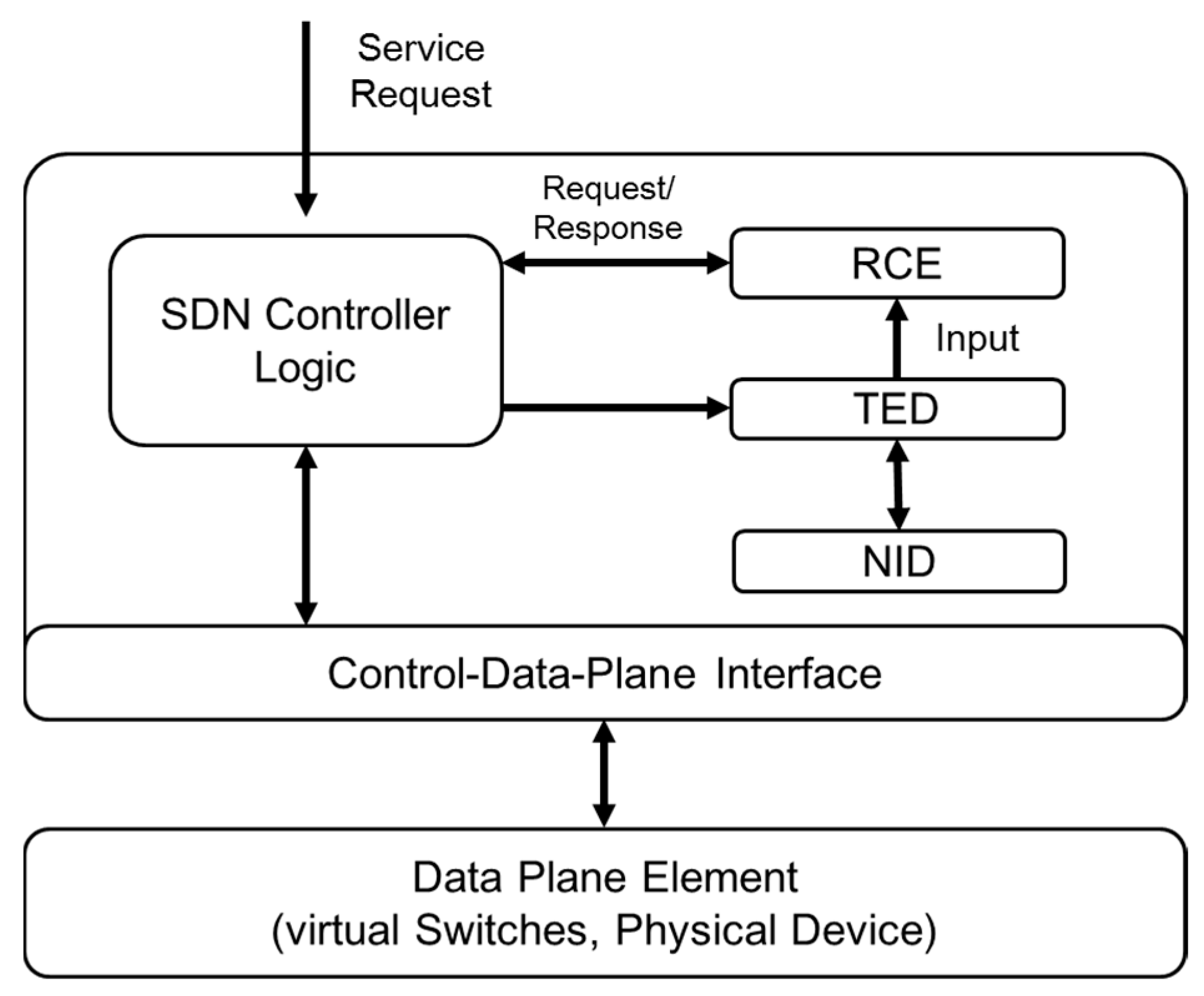
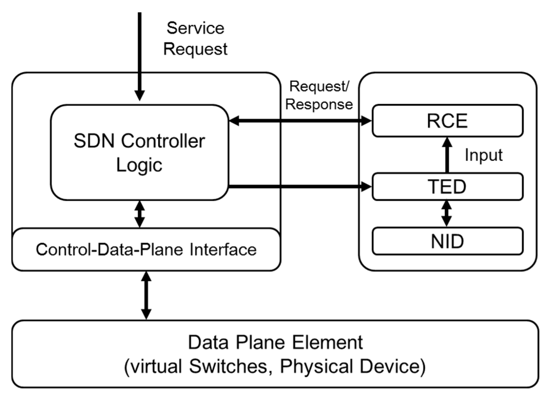
4.2. Architecture of SRC

- -
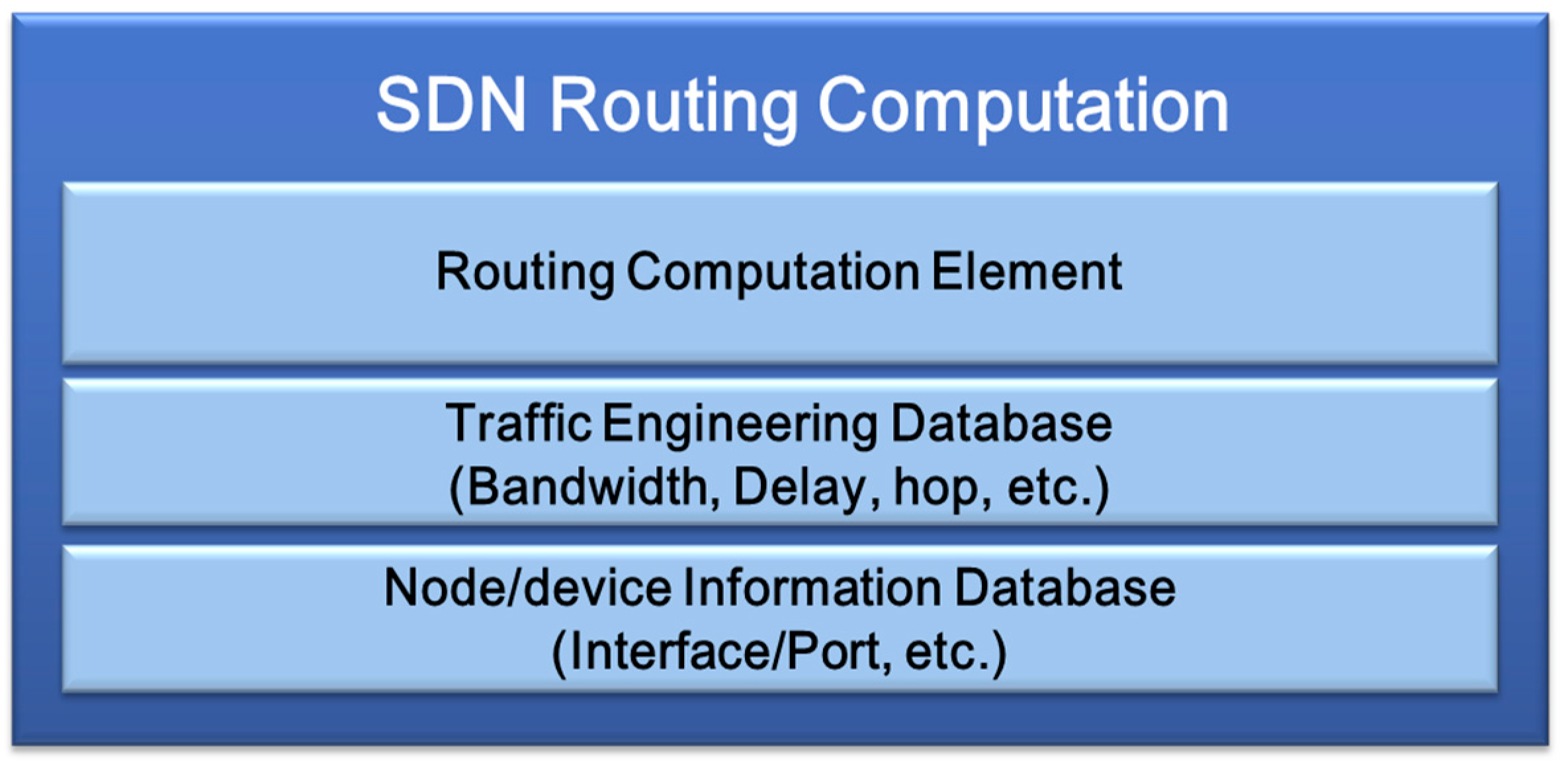
- Routing computation element (RCE): As the SDN controller requests the network path calculation to RCE, the RCE calculates all paths based on the source/database node information and the network performance elements (such as bandwidth, delay, etc.) received from TED.
- -
- Traffic engineering database (TED): TED is generated on the network domain resources and network topology information. It includes bandwidth, delay and jitters, and the RCE calculates the optimal path meeting the requirements using this information.
- -
- Node/device information database (NID): NID saves basic network connection status within the corresponding domain for prompt path calculation and regularly updates the data.
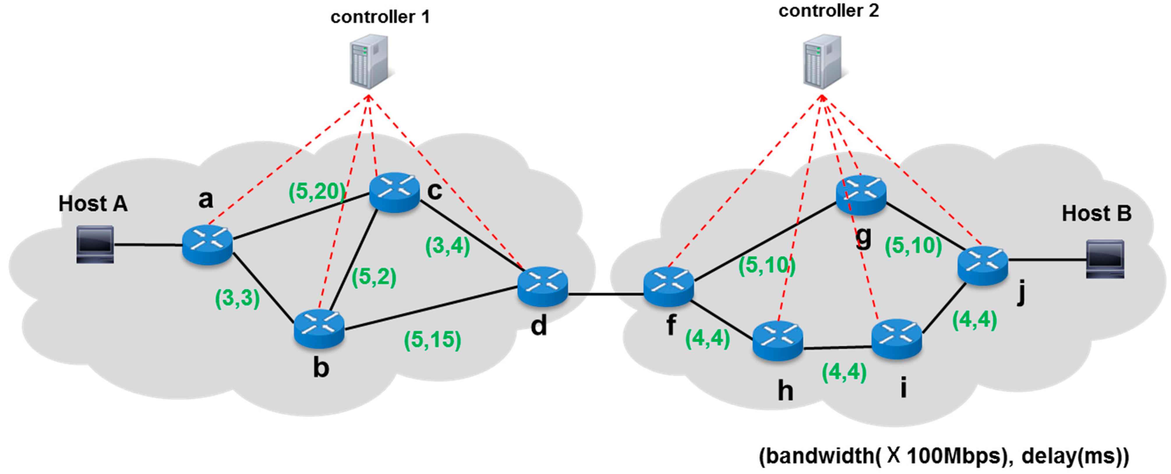
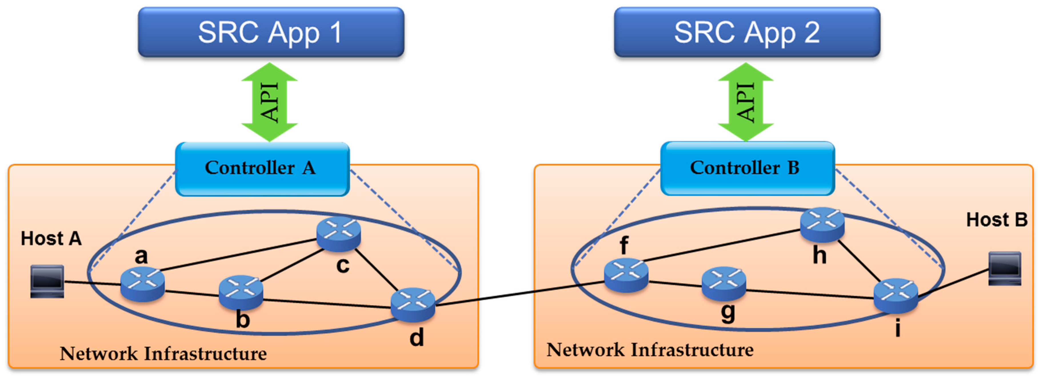
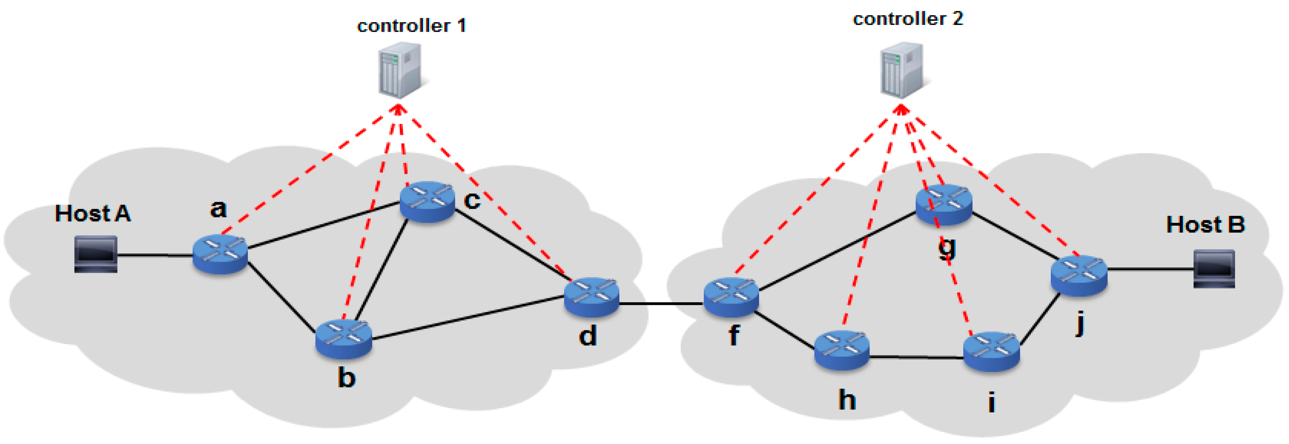
4.3. Application of SRC in Multi-Domain Environment


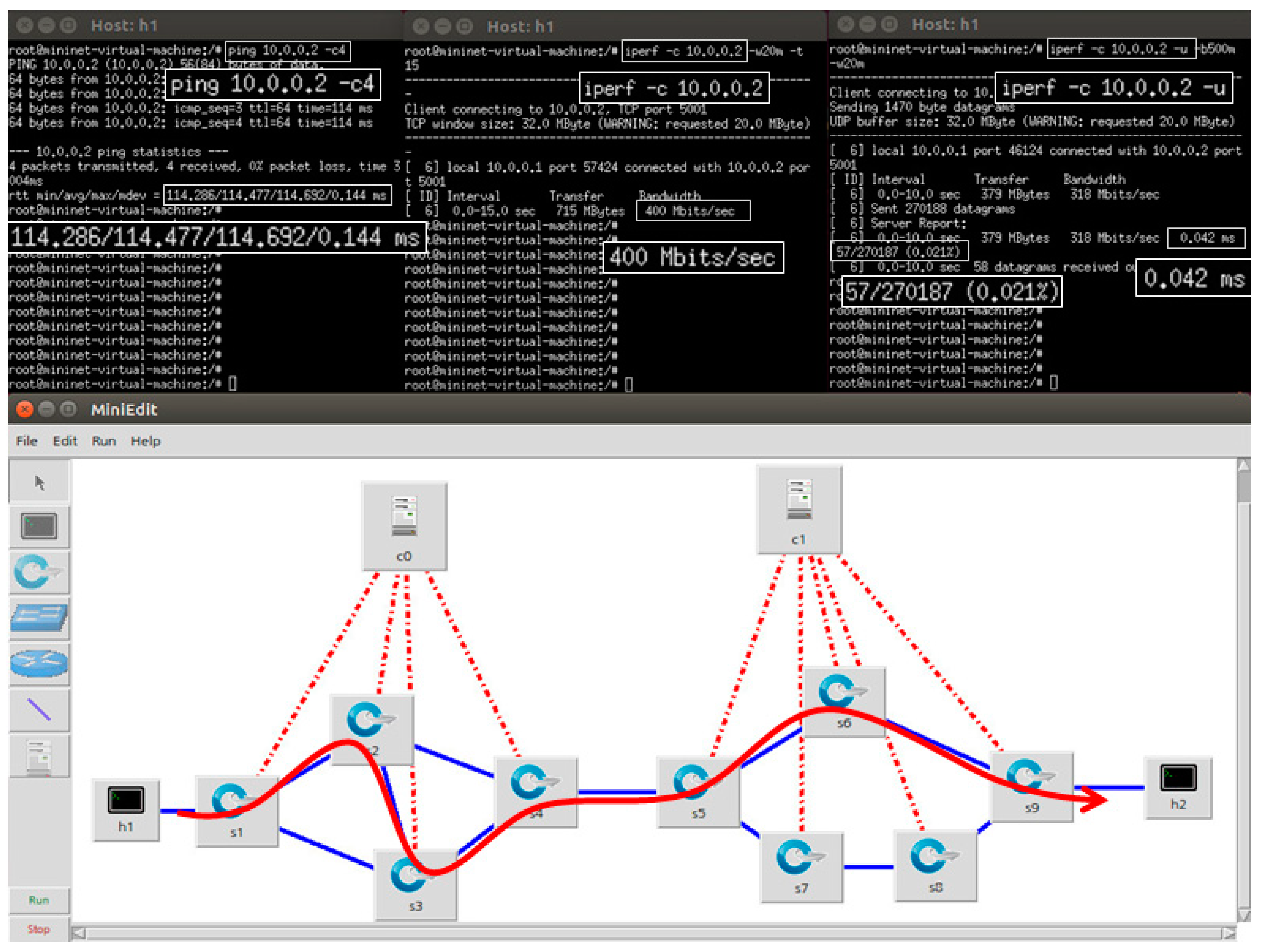
5. Performance Evaluation
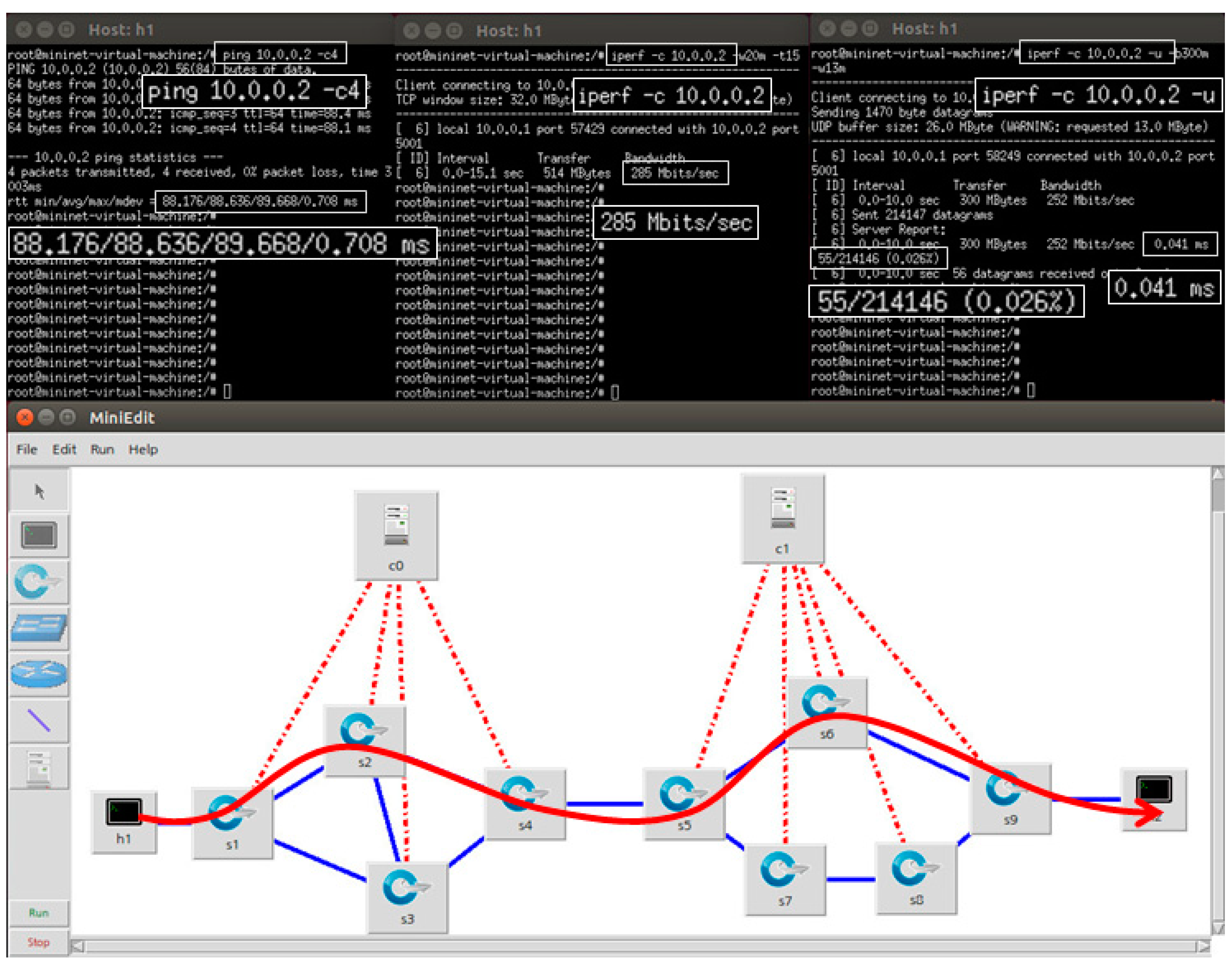
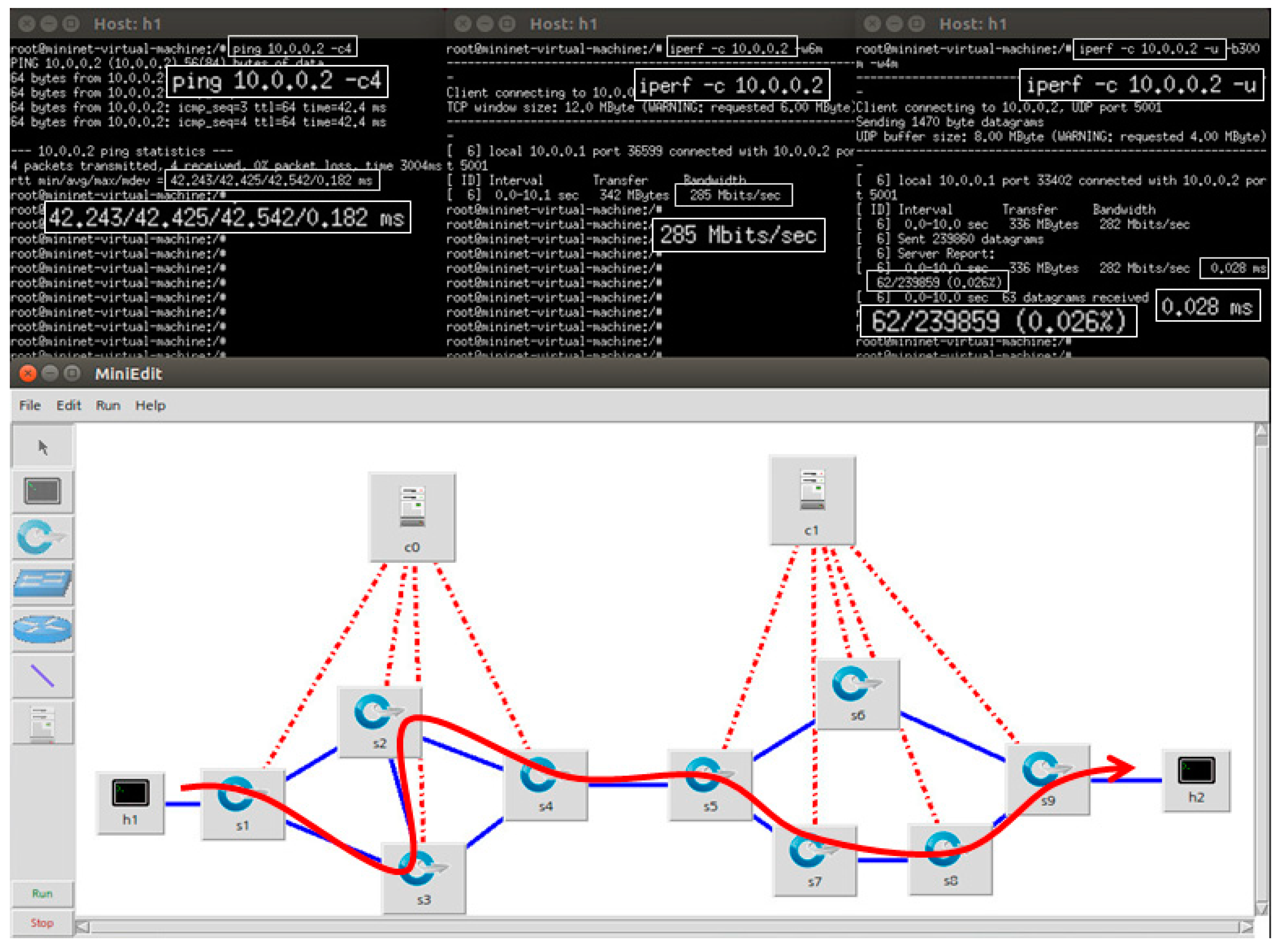
5.1. Organize Testbed

5.2. Configuration and Evaluation


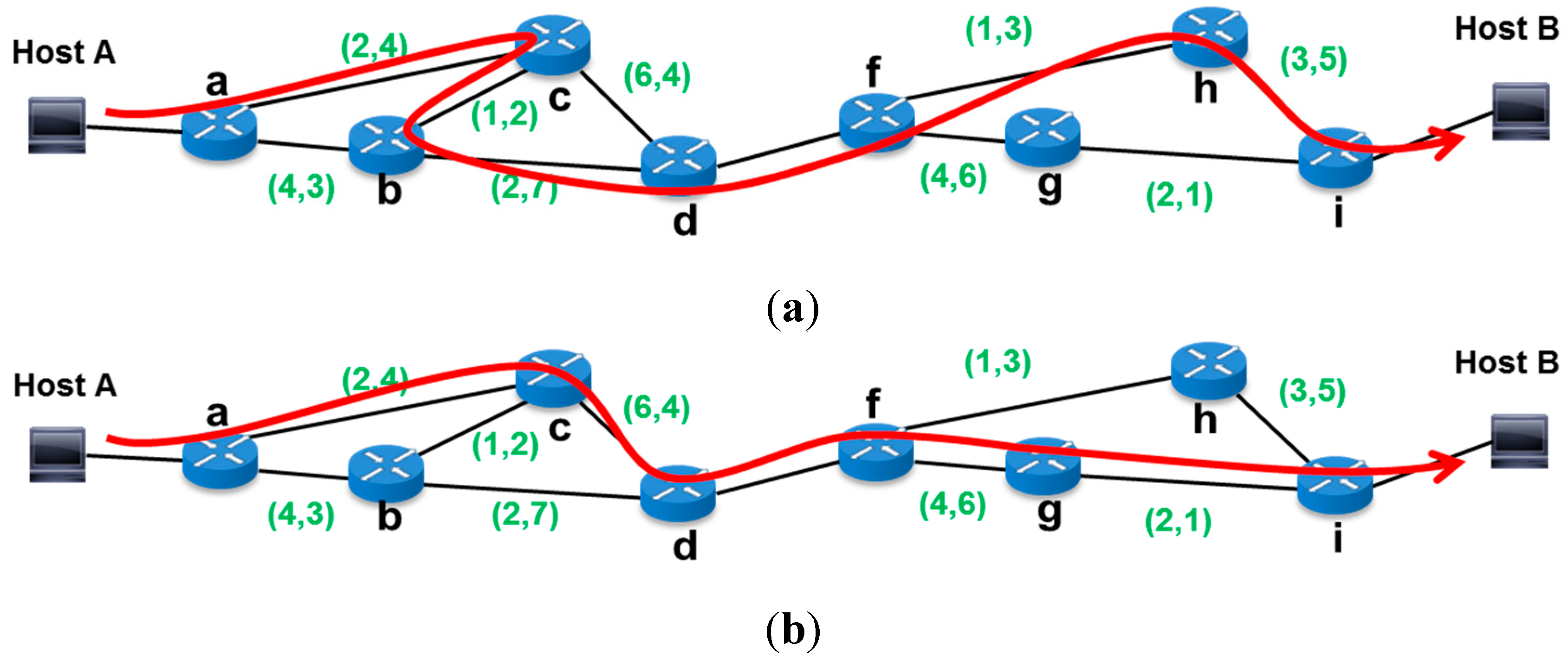
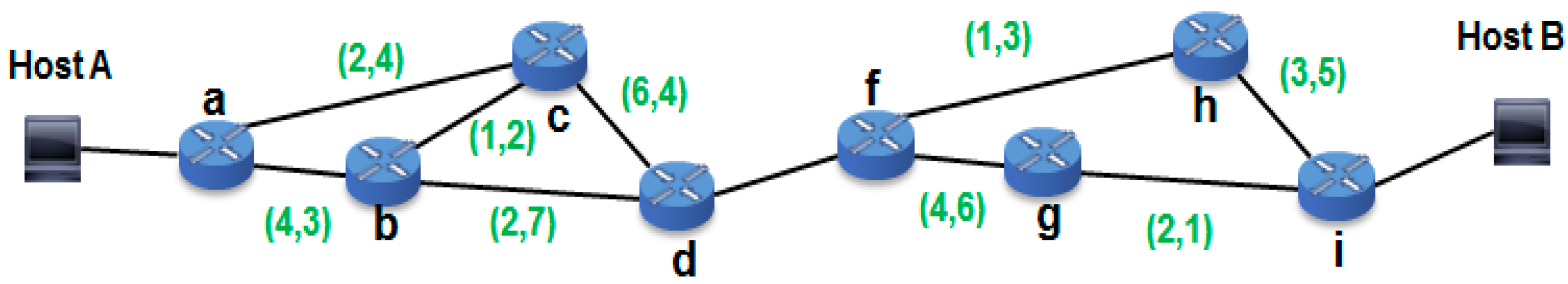
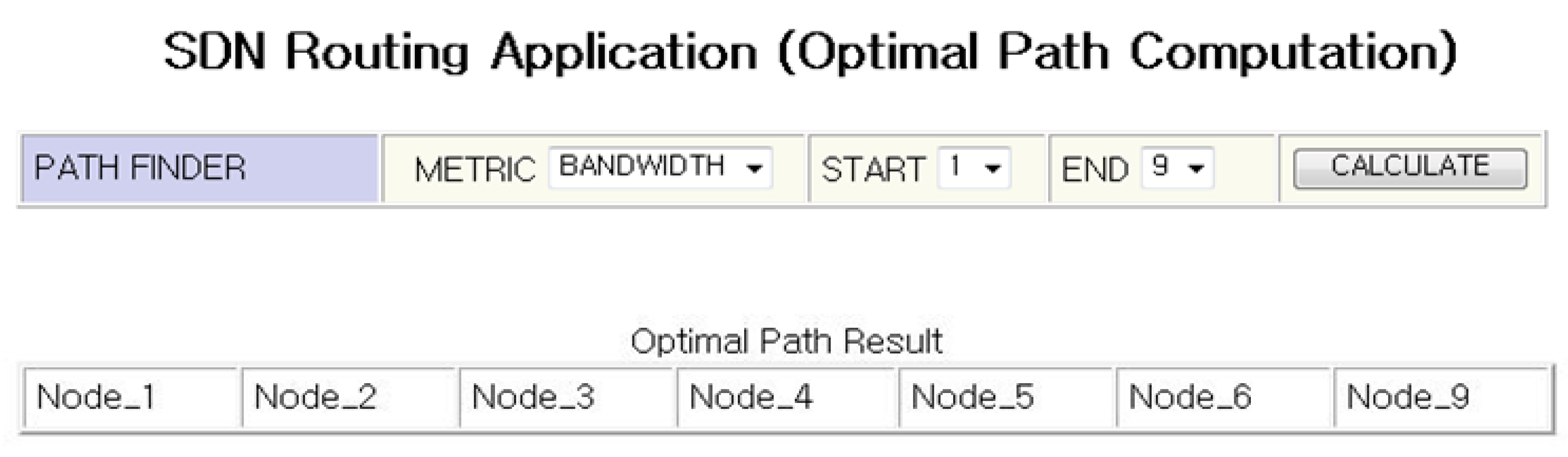
| Path | No. of hops | Metric (Bandwidth) | Average Throughput (Mbps) | |
|---|---|---|---|---|
| Path 1 (Min hops) | a-c-d-f-g-j | 6 | 22 | 285 |
| Path 2 (Bandwidth) | a-c-b-d-f-g-j | 7 | 25 | 400 |

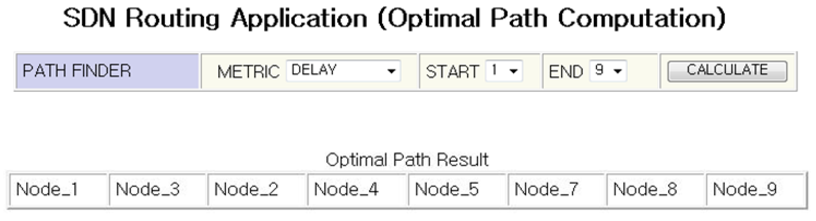
| Path | No. of hops | Metric (Delay) | Average Delay (ms) | |
|---|---|---|---|---|
| Path 1 (Min hops) | a-c-d-f-g-j | 6 | 34 | 88.6 |
| Path 3 (Delay) | a-b-c-d-f-h-i-j | 8 | 21 | 42.4 |
6. Conclusions
Author Contributions
Conflicts of Interest
References and Notes
- Yu, J. A technical trend and prospect of software defined network and OpenFlow. KNOM Rev. 2012, 15, 1–24. [Google Scholar]
- Jain, S.; Kumar, A.; Mandal, S.; Ong, J.; Poutievski, L.; Singh, A.; Venkata, S.; Wanderer, J.; Zhou, J.; Zhu, M.; et al. B4: Experience with a globally-deployed software defined WAN. In Proceedings of the ACM SIGCOMM 2013 Conference on SIGCOMM, Hong Kong, China, 12–16 August 2013; pp. 3–14.
- Weng, M.M.; Shih, T.K.; Hung, J.C. A personal tutoring mechanism based on the cloud environment. J. Converg. 2013, 44, 37–44. [Google Scholar]
- Open Networking Foundation (ONF). Software-Defined Networking: The New Norm for Networks, ONF: Palo Alto, CA, USA, 2012.
- SDN4FNS. Available online: http://site.ieee.org/sdn4fns/whitepaper/ (accessed on 8 September 2014).
- Open Networking Foundation (ONF). SDN Architecture Overview, Version 1.0; ONF: Palo Alto, CA, USA, 2013.
- Bifulco, R.; Schneider, F. OpenFlow rules interaction: Definition and detection. In Proceedings of the 2013 IEEE SDN for Future Networks and Services, Trento, Italy, 11–13 November 2013.
- Bigswitch Networks. Available online: http://www.bigswitch.com/products/SDN-Controller (accessed on 14 October 2014).
- Scott-Hayward, S.; O’Callaghan, G.; Sezer, S. SDN security: A survey. In Proceedings of the 2013 IEEE SDN for Future Networks and Services, Trento, Italy, 11–13 November 2013.
- Salvestrini, F.; Carrozzo, G.; Ciulli, N. Towards a distributed SDN control: Inter-platform signaling among flow processing platforms. In Proceedings of the 2013 IEEE SDN for Future Networks and Services, Trento, Italy, 11–13 November 2013.
- Mechtri, M.; Houidi, I.; Louati, W.; Zeghlache, D. SDN for inter cloud networking. In Proceedings of the 2013 IEEE SDN for Future Networks and Services, Trento, Italy, 11–13 November 2013.
- Gnanaraj, J.; Kathrine, W.; Ezra, K.; Rajsingh, E.B. Smart card based time efficient authentication scheme for global grid computing. Hum. Cent. Comput. Inf. Sci. 2013. [Google Scholar] [CrossRef]
- Path Computation Element (PCE)—IETF RFC’s 4665 and RFC 5.
- Vasseur, J.P.; Roux, J.L.; Ayyangar, A.; Oki, E.; Atlas, A.; Dolganow, A. Path Computation Element (PCE) Communication Protocol(PCEP), 1st ed.; IETF Trust: Reston, VA, USA, 2005. [Google Scholar]
- Farrel, A.; Vasseur, J.-P.; Ash, J. A Path Computation Element (PCE)-Based Architecture; IETF Trust: Reston, VA, USA, 2006. [Google Scholar]
- Matsuura, H.; Morita, N.; Murakami, T.; Takami, K. Hierarchically distributed PCE for GMPLS multilayered networks. In Proceedings of the IEEE Globecom 2005, St. Louis, MO, USA, 28 November–2 December 2005.
- Aslam, F.; Uzmi, Z.A.; Farrel, A. Interdomain path computation: Challenges and solutions for label switched networks. IEEE Commun. Mag. 2007, 45, 94–101. [Google Scholar] [CrossRef]
- Qin, Y.; Mason, L.; Jia, K. Study on a joint multiple layer restoration scheme for IP over WDM networks. IEEE Netw. 2003, 17, 43–48. [Google Scholar] [CrossRef]
- Open Networking Foundation (ONF). Operator Network Monetization, Through OpenFlow™-Enabled SDN, ONF: Palo Alto, CA, USA, 2013.
- Phemius, K.; Bouet, M.; Leguay, J. DISCO: Distributed multi-domain SDN controller. In Proceedings of 2014 IEEE Network Operations and Management Symposium, Krakow, Poland, 5–9 May 2014; pp. 1–4.
- Mahajan, K.; Makroo, A.; Dahiya, D. Round robin with server affinity: A VM load balancing algorithm for cloud based infrastructure. J. Inf. Process. Syst. 2013, 9, 379–394. [Google Scholar] [CrossRef]
- Vasseur, J.P.; Ayyangar, A.; Zhang, R. A Per-Domain Path Computation Method for Establishing Inter-Domain Traffic Engineering (TE) Label Switched Paths (LSPs); IETF Trust: Reston, VA, USA, 2007. [Google Scholar]
- López, V.; Huiszoon, B.; Fernandez-Palacios, J.P.; Gonzalez de Dios, O.; Aracil, J. Path computation element in telecom networks: Recent developments and standardization activities. In Proceedings of the 14th Conference on Optical Network Design and Modeling (ONDM), Kyoto, Japan, 1–3 February 2010; pp. 1–6.
- Vasseur, J.P.; Zhang, R.; Bitar, N.; le Roux, J.L. A Backward-Recursive PCE-Based Computation (BRPC) Procedure to Compute Shortest Constrained Inter-Domain Traffic Engineering Label Switched Paths; IETF Trust: Reston, VA, USA, 2009. [Google Scholar]
- OpenDaylight Foundation. Available online: http://www.opendaylight.org (accessed on 20 May 2014).
- OpenDaylight. Available online: https://wiki.opendaylight.org/view (accessed on 25 August 2014).
© 2015 by the authors; licensee MDPI, Basel, Switzerland. This article is an open access article distributed under the terms and conditions of the Creative Commons Attribution license (http://creativecommons.org/licenses/by/4.0/).
Share and Cite
Cho, H.; Park, J.; Gil, J.-M.; Jeong, Y.-S.; Park, J.H. An Optimal Path Computation Architecture for the Cloud-Network on Software-Defined Networking. Sustainability 2015, 7, 5413-5430. https://doi.org/10.3390/su7055413
Cho H, Park J, Gil J-M, Jeong Y-S, Park JH. An Optimal Path Computation Architecture for the Cloud-Network on Software-Defined Networking. Sustainability. 2015; 7(5):5413-5430. https://doi.org/10.3390/su7055413
Chicago/Turabian StyleCho, Hyunhun, Jinhyung Park, Joon-Min Gil, Young-Sik Jeong, and Jong Hyuk Park. 2015. "An Optimal Path Computation Architecture for the Cloud-Network on Software-Defined Networking" Sustainability 7, no. 5: 5413-5430. https://doi.org/10.3390/su7055413