
Design and Assessment of an IGCC Concept with CO2 Capture for the Co-Generation of Electricity and Substitute Natural Gas

Abstract
:1. Introduction

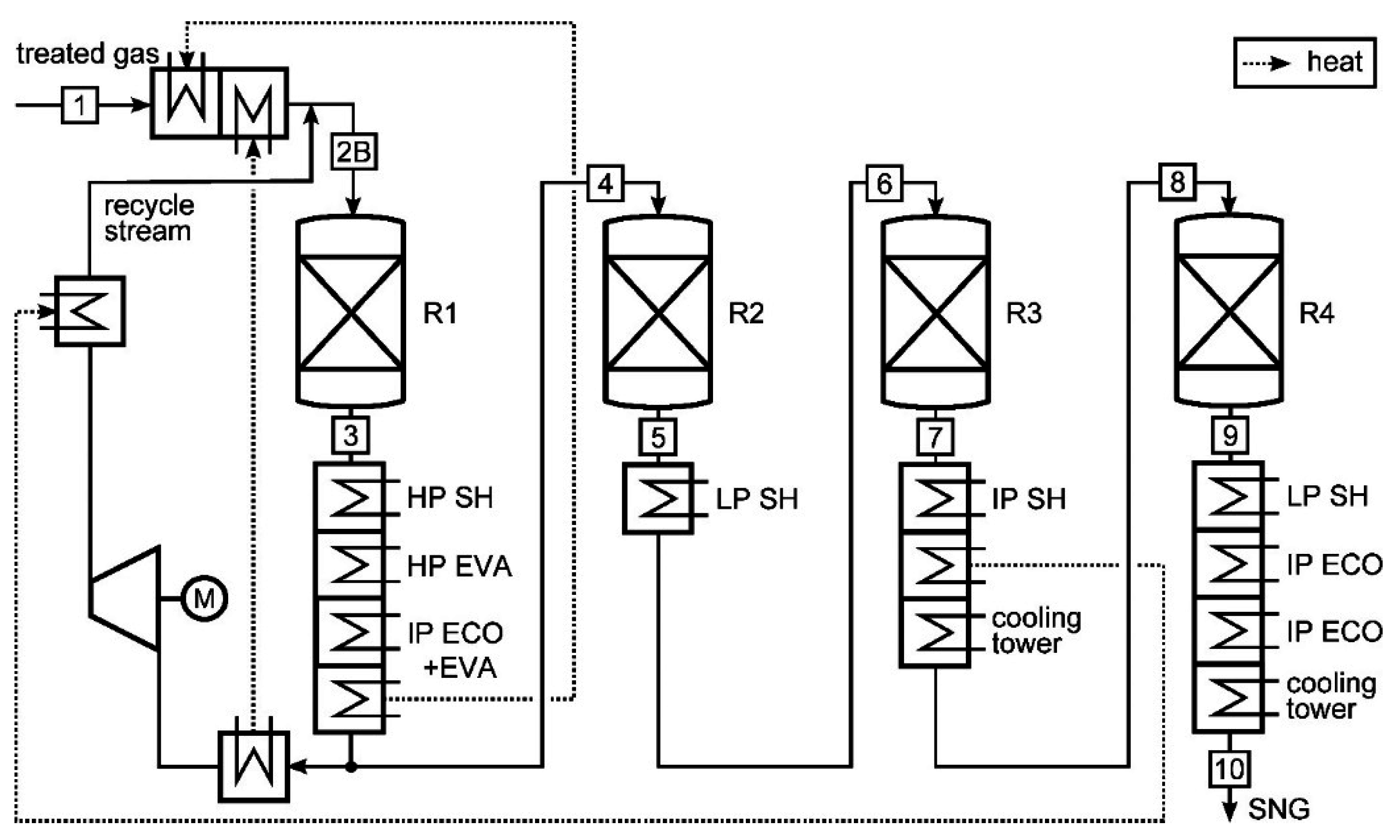
| Reaction | ΔHr (kJ/mol) | ||
|---|---|---|---|
| CO + 3H2 ↔ CH4 + H2O | CO methanation | −206.28 | R1 |
| CO2 + 4H2 ↔ CH4 + 2H2O | CO2 methanation | −165.12 | R2 |
| CO + H2O ↔ H2 + CO2 | Water-gas shift reaction | −41.16 | R3 |
| C2H4 + 2H2O ↔ 2CO + 4H2 | Hydration of ethene | +210 | R4 |
| 2H2 + 2CO ↔ CH4 + CO2 | Hydration of CO | −247 | R5 |
| 2CO ↔ C + CO2 | Boudouard reaction | −173 | R6 |
| 2H2 + C ↔ CH4 | Hydrogasification | −74 | R7 |
| CH4 + H2O ↔ CO + H2 | Steam reforming | +206 | R8 |
2. Assumptions, Methodology and Simulation
| Component/System | Unit | Value |
|---|---|---|
| General | ||
| Ambient conditions | K, bar | 288, 1.013 |
| Mechanical efficiency of turbo-machinery | % | 99–99.5 |
| Electrical generator efficiency | % | 99 |
| Electrical motor efficiency | % | 95 |
| ASU | ||
| Electric motor efficiency | % | 98 |
| Outlet pressure HP/LP column | bar | 5.8/1.3 |
| Gasification Island | ||
| Coal mill electrical demand | kJ/kg | 36 |
| Concentration of slurry to gasifier [25] | % | 44 |
| Carbon conversion efficiency [25] | % | 98 |
| Heat loss gasifier (HHVas) | % | 0.5 |
| O2 gasification agent pressure | bar | 38 |
| O2 compressor isentropic efficiency | % | 85 |
| Gasification temperature | °C | 1250 |
| Radiant cooler raw gas temperature [25] | °C | 667 |
| Pressure loss scrubber | bar | 0.3 |
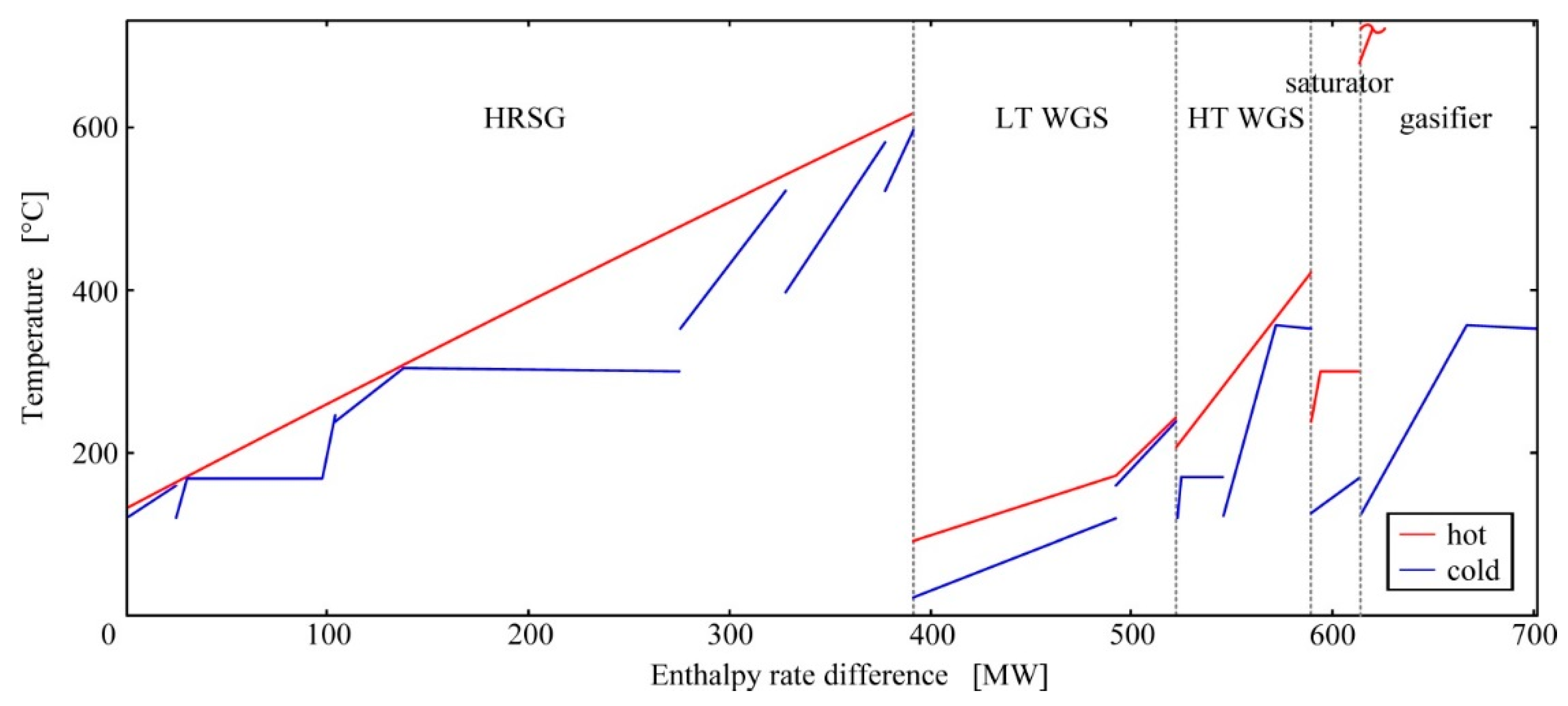
| Water gas shifter | ||
| HT-shifter inlet temperature [25] | °C | 225 |
| LT-shifter inlet temperature [25] | °C | 204 |
| Steam demand by outlet mole fraction of CO [26] | % | 1.9 |
| Pressure loss [25] | bar | 0.3 |
| Acid gas removal (AGR) | ||
| Offgas temperature at the inlet | °C | 30 |
| LP steam production per kg of H2S [27] | MJ/kg | 29.5 |
| Solvent pumps isentropic efficiency | % | 75–85 |
| Solvent/gas mole ratio H2S absorber | - | 0.2 |
| Solvent/gas mole ratio CO2 absorber, based on [27] | - | 1.26 |
| Refrigeration compressor isentropic efficiency [28] | % | 78 |
| CO2 compressor isentropic stage efficiency [28] | % | 77.2–81.5 |
| CO2 exit conditions | °C, bar | 45, 110 |
| Claus plant | ||
| Combustion temperature | °C | 1050 |
| H2S/SO2 mole ratio [29] | - | 2 |
| Gas turbine system | ||
| Turbine inlet temperature (TIT) | °C | 1253 |
| Air compressor isentropic efficiency | % | 88.2 |
| Gas turbine isentropic efficiency | % | 87.9 |
| TREMPTM | ||
| Recycle rate | % | 70 |
| Recycle-pump isentropic efficiency | % | 87 |
| Outlet temperature of product | °C | 35 |
| Steam cycle | ||
| Steam-turbine isentropic efficiency HP, IP, LP [30] | % | 94.2, 96, 89 |
| Isentropic efficiency of pumps | % | 85 |
| Condenser pressure | bar | 0.035 |
| Pinch-point temperature difference for gas/gas, gas/liquid, liquid/liquid heat transfer | K | 20, 10, 5 |
3. System Design
3.1. Base Case
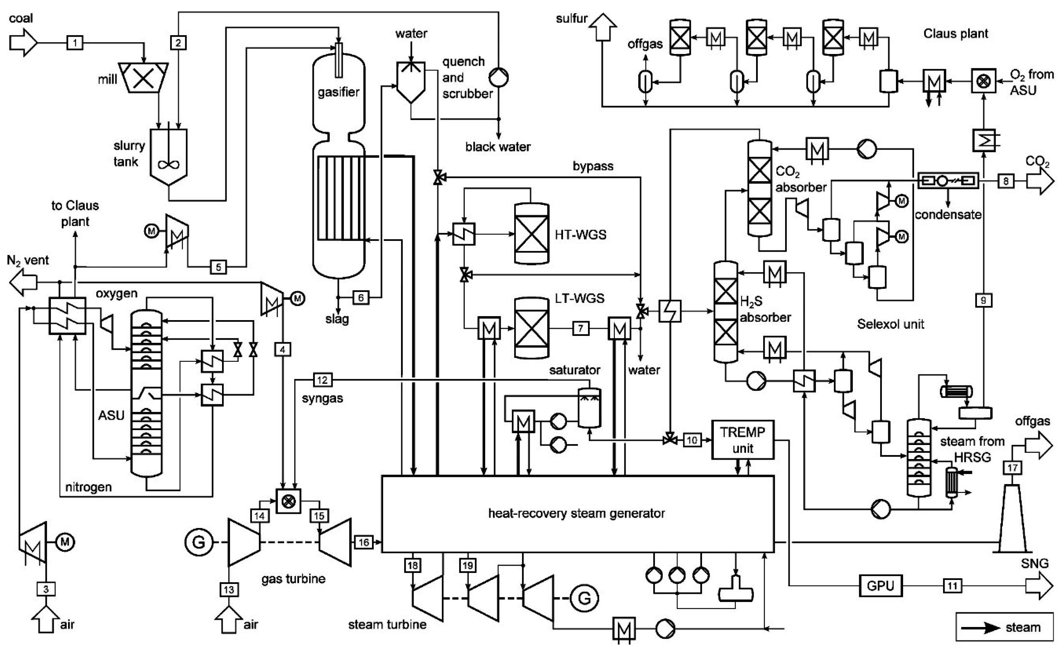
| Flow No. | Type | Temperature | Pressure | Mass Flow |
|---|---|---|---|---|
| (°C) | (bar) | (kg/s) | ||
| 1 | Coal | 15.0 | 1.013 | 50.0 |
| 2 | Water | 177.3 | 35.7 | 22.0 |
| 3 | Air | 15.0 | 1.013 | 164.1 |
| 4 | Nitrogen | 126.6 | 26 | 124.1 |
| 5 | Oxygen | 93.6 | 38.0 | 40.0 |
| 6 | Raw gas | 677.0 | 35.6 | 87.8 |
| 7 | Shift gas | 243.9 | 34.4 | 165.2 |
| 8 | CO2 (BASE case) | 45.0 | 110.0 | 108.0 |
| CO2 (SNG case) | 45.0 | 110.0 | 70.1 | |
| 9 | Acid gas (BASE case) | 24.9 | 1.3 | 1.3 |
| Acid gas (SNG case) | 28.9 | 1.3 | 1.3 | |
| 10 | Syngas | 19.8 | 34 | 32.3 |
| 11 | SNG | 35 | 26.9 | 32.3 |
| 12 | Syngas | 130.9 | 34 | 16.7 |
| 13 | Air | 15.0 | 1.0 | 539.9 |
| 14 | Air | 426.1 | 19.5 | 539.9 |
| 15 | Combustion gas | 1253.0 | 19.5 | 680.8 |
| 16 | Exhaust gas | 588.6 | 1.1 | 680.8 |
| 17 | Offgas (BASE case) | 133.2 | 1.02 | 680.8 |
| 18 | Steam (BASE case) | 597.4 | 168.0 | 246.1 |
| Steam (SNG case) | 450.4 | 129.8 | 62.7 | |
| 19 | Steam (BASE case) | 582.4 | 85.0 | 143.8 |
| Steam (SNG case) | 306.6 | 41.6 | 104.4 |
3.2. SNG Case

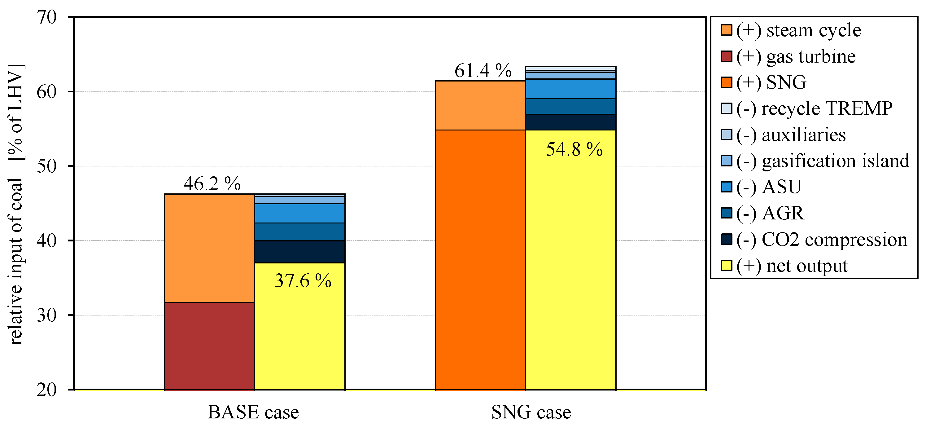
4. Results and Discussion

| Unit | BASE Case | SNG Case | |
|---|---|---|---|
| live steam pressure HP | bar | 168.0 | 129.8 |
| live steam pressure IP | bar | 85.0 | 41.6 |
| live steam pressure LP | bar | 7.7 | 5.9 |
| live steam temperature HP | °C | 597.4 | 450.4 |
| live steam temperature IP | °C | 582.4 | 306.6 |
| live steam temperature LP | °C | 119.1 | 317.4 |
| mass flow | kg/s | 246.1 | 187.1 |
| heat input | MW | 549.9 | 297.1 |
| heat output | MW | −203.4 | −166.1 |
| generated electricity | MW | 192.7 | 90.2 |
5. Conclusions
Author Contributions
Conflicts of Interest
References
- Petroleum, B. BP Statistical Review of World Energy; BP: London, UK, 2012. [Google Scholar]
- US Energy Information Administration. International Energy Outlook; US Energy Information Administration: Washington, DC, USA, 2013. [Google Scholar]
- Sudiro, M.; Bertucco, A. Synthetic Natural Gas (SNG) from coal and biomass: A Survey of Existing Process Technologies, Open Issues and Perspectives. Available online: http://www.intechopen.com/books/natural-gas/synthetic-natural-gas-sng-from-coal-and-biomass-a-survey-of-existing-process-technologies-open-issue (accessed on 2 December 2015).
- Gärtner, C.; Gutte, H.; Franke, P.; Bauersfeld, S.; Scheithauer, D.; Meyer, B.; Pardemann, R.; Boblenz, R. Forschungsvorhaben Untersuchung zur Energetisch und Wirtschaftlich Optimierten Kohleverstromung Durch Polygeneration: Schlussbericht—Teile I und II: Kurzdarstellung und Eingehende Darstellung. Available online: https://getinfo.de/en/search/download/?tx_tibsearch_search[docid]=TIBKAT%3A727482947&cHash=b0b7ae97c185bbbe234224a6279b0d0a (accessed on 2 December 2015). (In German)
- Seglin, L.; Gould, R.F. Methanation of Synthesis Gas; American Chemical Society: Atlantic City, NJ, USA, 1974. [Google Scholar]
- Kopyscinski, J.; Schildhauer, T.J.; Biollaz, S. Production of Synthetic Natural Gas (SNG) from coal and dry biomass—A technology review from 1950 to 2009. Fuel 2010, 89, 1763–1783. [Google Scholar] [CrossRef]
- Buttler, A.; Kunze, C.; Spliethoff, H. IGCC-EPI: Decentralized concept of a highly load-flexible IGCC power plant for excess power integration. Appl. Energy 2013, 104, 869–879. [Google Scholar] [CrossRef]
- Rönsch, S.; Ortwein, A. Methanisierung von Synthesegasen—Grundlagen und Verfahrensentwicklungen (German). Chem. Ing. Tech. 2011, 83, 1200–1208. [Google Scholar] [CrossRef]
- Ogriseck, K. Untersuchung von IGCC-Kraftwerkskonzepten mit Polygeneration und CO2-Abtrennung; Technical Report VDI Reihe 6 Nr. 544; VDI Publishing House: Freiberg, Germany, 2006. (In German) [Google Scholar]
- Jensen, J.; Poulsen, J.; Andersen, N. From coal to clean energy. In Proceedings of the Nitrogen + Syngas 2011 International Conference & Exhibition, Düsseldorf, Germany, 21–24 February 2011.
- Götz, M.; Heinrich, T.; Graf, F.; Bajohr, S.; Baundry, A. Methanisierung—Technische Ansätze und deren Bewertung. In Proceedings of the International Biomass Conference, Leipzig, Germany, 4–6 May 2010.
- Topsoe, H. From Solid Fuels to Substitute Natural Gas (SNG) Using TREMPTM; Haldor Topsøe: Lyngby, Denmark, 2009. [Google Scholar]
- Li, S.; Jin, H.; Zhang, X. Exergy analysis and the energy saving mechanism for coal to synthetic/substitute natural gas and power co generation without and with CO2-capture. Appl. Energy 2014, 130, 552–561. [Google Scholar] [CrossRef]
- Li, S.; Ji, X.; Zhang, X.; Gao, L.; Jin, H. Coal to SNG: Technical progress, modeling and system optimization through exergy analysis. Appl. Energy 2014, 136, 98–109. [Google Scholar] [CrossRef]
- Gassner, M.; Maréchal, F. Thermo-economic process model for thermochemical production of Synthetic Natural Gas (SNG) from lignocellulosic biomass. Biomass Bioenergy 2009, 33, 1587–1604. [Google Scholar] [CrossRef]
- Koytsoumpa, E.I.; Atsonios, K.; Panopoulos, K.D.; Karellas, S.; Kakaras, E.; Karl, J. Modelling and assessment of acid gas removal processes in coal-derived SNG production. Appl. Therm. Eng. 2015, 74, 128–135. [Google Scholar] [CrossRef]
- Li, S.; Jin, H.; Lin, G.; Zhang, X.; Ji, X. Techno-economic performance and cost reduction potential for the substitute/synthetic natural gas and power cogeneration plant with CO2-capture. Energy Convers. Manag. 2014, 85, 875–885. [Google Scholar] [CrossRef]
- Li, S.; Jin, H.; Lin, G. Coal based cogeneration system for synthetic/substitute natural gas and power with CO2 capture after methanation: Coupling between chemical and power production. J. Eng. Gas Turbines Power 2014. [Google Scholar] [CrossRef]
- Li, S.; Jin, H.; Gao, L. Cogeneration of substitute natural gas and power from coal by moderate recycle of the chemical unconverted gas. Energy 2013, 55, 658–667. [Google Scholar] [CrossRef]
- Karellas, S.; Panopoulos, K.D.; Panousis, G.; Rigas, A.; Karl, J.; Kakaras, E. An evaluation of Substitute natural gas production from different coal gasification processes based on modeling. Energy 2012, 45, 183–194. [Google Scholar] [CrossRef]
- Bu, X.P.; Wang, P.; Xin, S.H.; Liang, D.M.; Gi, X.G. Analysis of coal gasification/polygeneration to produce Substitute Natural Gas (SNG). Coal Chem. Ind. 2007, 6, 4–7. [Google Scholar]
- Aspen Plus®. Available online: http://www.aspentech.com (accessed on 2 December 2015).
- Ebsilon. Available online: https://www.steag-systemtechnologies.com/ebsilon_professional.html (accessed on 2 December 2015).
- Stodola, A. Dampf- und Gasturbinen; Julius Springer: Berlin, Germany, 1924. (In German) [Google Scholar]
- Black, J. Cost and Performance Baseline for Fossil Energy Plants—Volume 1: Bituminous Coal and Natural Gas to Electricity; National Energy Technology Laboratory: Washington, DC, USA, 2010. [Google Scholar]
- Ullmann, F. Ullmann’s Encyclopedia of Industrial Chemistry; Wiley-VCH: Weinheim, Germany, 1998. [Google Scholar]
- Doctor, R.D.; Molburg, J.C.; Thimmapuram, P.R. KRW Oxygen-Blown Gasification Combined Cycle: Carbon Dioxide Recovery, Transport, and Disposal; Energy Systems Division, Argonne National Laboratory: Lemont, IL, USA, 1996. [Google Scholar]
- Ludwig, E. Applied Process Design III; Gulf Professional Publishing: Houston, TX, USA, 2001. [Google Scholar]
- Schoofs, G.R. Sulfur Condensation in Claus Catalyst; Hydrocarbon Processings: Houston, TX, USA, 1985. [Google Scholar]
- Deckers, M. CFX Aids Design of World’s most Efficient Steam Turbine. Available online: http://www.ansys.com/staticassets/ANSYS/staticassets/resourcelibrary/article/CFXU-23-Sum03-CFX-Aids-Design-of-Worlds-Most-Efficient-Steam-Turbine.pdf (accessed on 2 December 2015).
- Siemens Gas Turbines. Available online: http://www.energy.siemens.com/hq/en/fossil-power-generation/gas-turbines/sgt5-4000f.html (accessed on 2 December 2015).
- Chandel, M.; Williams, E. Synthetic Natural Gas (SNG): Technology, Environmental Implications, and Economics; Duke University: Durham, NC, USA, 2009. [Google Scholar]
- Bejan, A.; Tsatsaronis, G.; Moran, M. Thermal Design and Optimization; John Wiley & Sons, Inc.: Hoboken, NJ, USA, 1996. [Google Scholar]
© 2015 by the authors; licensee MDPI, Basel, Switzerland. This article is an open access article distributed under the terms and conditions of the Creative Commons by Attribution (CC-BY) license (http://creativecommons.org/licenses/by/4.0/).
Share and Cite
Blumberg, T.; Sorgenfrei, M.; Tsatsaronis, G. Design and Assessment of an IGCC Concept with CO2 Capture for the Co-Generation of Electricity and Substitute Natural Gas. Sustainability 2015, 7, 16213-16225. https://doi.org/10.3390/su71215811
Blumberg T, Sorgenfrei M, Tsatsaronis G. Design and Assessment of an IGCC Concept with CO2 Capture for the Co-Generation of Electricity and Substitute Natural Gas. Sustainability. 2015; 7(12):16213-16225. https://doi.org/10.3390/su71215811
Chicago/Turabian StyleBlumberg, Timo, Max Sorgenfrei, and George Tsatsaronis. 2015. "Design and Assessment of an IGCC Concept with CO2 Capture for the Co-Generation of Electricity and Substitute Natural Gas" Sustainability 7, no. 12: 16213-16225. https://doi.org/10.3390/su71215811