1. Introduction
Artificial optical radiation (AOR) is emitted by a very wide range of sources that people may be exposed to, in the workplace and elsewhere. In order to guarantee sufficient safety minimizing the artificial optical radiation hazard, different technical reports and guidelines have been issued by international institutions [
1,
2,
3,
4,
5,
6].
AOR is separated into laser and non-coherent radiation in [
5,
6]. The non-coherent sources are defined as all of the sources, apart from laser, that emit any radiation in the optical wavelength range of 100 nm to 1 mm [
5]. Among the non-coherent sources [
1,
6,
7], special attention has been paid to industrial process equipment (e.g., welding, paint drying ovens, melting of metal and glass,
etc.) and medical equipment (e.g., neonatal phototherapy lamps, sterilization, surgical lights,
etc.), while minor attention has been paid to non-coherent sources widely used in offices (e.g., lamps/luminaries, display screen equipment, copiers, LED for lighting and signalization,
etc.).
Nowadays the sources most used for the lighting of workplaces (particularly offices) are fluorescent lamps [
7,
8,
9]. With their efficacy, approaching that of fluorescent lamps, their long durability, small size and low weight, LEDs are very often used to replace existing lamps [
9,
10,
11]. These new applications have placed increasingly stringent demands on the optical characterization of LEDs, which serves as the fundamental baseline for product quality and product design [
8,
12,
13,
14,
15,
16].
In this paper, the authors discuss the results of a measurement survey of AOR emitted by 8 W LED tubes suitable for substitution of 18 W tubular fluorescent lamps (length 60 cm), widely used for general lighting of workplaces. The irradiance and radiance values, both measured and evaluated in a wide range of wavelengths (from 180 nm to 3000 nm), have been analyzed in order to define the risk group of LED as a function of the maximum permissible exposure time as indicated in the European Standard EN 62471 [
17] and in the Technical Report IEC 62778 [
18]. By using the measurement results, some consideration about blue light hazard (wavelengths 300–700 nm) has been made regarding the prescriptions of the EU Directive 2006/25 [
5] on the minimum health and safety requirements for the exposure of workers to risks arising from AOR.
2. Risk Assessment for Human Exposure and Safety Assessment for the Lamps
2.1. Risk of Exposure to AOR
With reference to the risk of exposure, at the international level, it was considered necessary to introduce measures protecting workers from the risks arising from AOR, on their health and safety, in particular damage to the eyes and to the skin. In
Table 1, the risks of exposure to AOR (for eyes and skin) emitted by non-coherent sources are highlighted as a function of the wavelength [
6].
With the EU Directive 2006/25 [
5], the minimum requirements to protect workers against risks of exposure to AOR have been specified. The content of the EU Directive 2006/25 has been fully taken up by the Italian legislation, in particular: Legislative Decree 81/2008, Chapter V, Articles 213 to 218 and Annex XXXVII [
19].
The limit values for the risk of exposure fixed by the Italian legislation [
19], according to the EU Directive [
5], are shown in
Table 2 for the different wavelength ranges between 180 and 3000 nm.
Table 1.
Risks of exposure to artificial optical radiation (AOR) emitted by non-coherent sources as a function of the wavelength [
6].
Table 1.
Risks of exposure to artificial optical radiation (AOR) emitted by non-coherent sources as a function of the wavelength [6].
| Wavelength Range (nm) | Hazard | Bioeffect |
|---|
| 180–400 | Actinic UV skin and eye | Eye: photokeratitis; conjunctivitis; cataractogenesis
Skin: erythema; elastosis |
| 315–400 | UVA eye | Eye: cataractogenesis
Skin: - |
| 300–700 | Retinal blue light | Eye: photoretinitis.
Skin: - |
| Retinal blue light small source |
| 380–1400 | Retinal thermal | Eye: retinal burn.
Skin: - |
| 780–1400 | Retinal thermal, weak visual stimulus |
| 780–3000 | Infrared radiation eye | Eye: cornea burn; cataractogenesis.
Skin: - |
| 380–3000 | Thermal skin | Eye: -
Skin: burn |
Table 2.
Limit values specified in the Italian legislation [
19].
Table 2.
Limit values specified in the Italian legislation [19].
| Risk Index | Range | Limit Value (Legislative Decree 81/08) | Unit |
|---|
| Wavelength (nm) | Name |
|---|
| (a) | 180–400 | UVA, UVB, UVC | Heff = 30 | J/m2 |
| (b) | 315–400 | UVA | HUVA = 104 | J/m2 |
| (c) | 300–700 | Blue Light | LB = 106·t−1 | W/m2sr |
| (d) | Blue Light | LB = 100 | W/m2sr |
| (g) | 380–1400 | Visible, IRA | LR = (2.8·107) Cα−1 | W/m2sr |
| (h) | Visible, IRA | LR = (5·107) Cα−1·t−0.25 | W/m2sr |
| (i) | Visible, IRA | LR = (8.89·108) Cα−1 | W/m2sr |
| (j) | 780–1400 | IRA | LR = (6·106) Cα−1 | W/m2sr |
| (k) | IRA | LR = (5·107) Cα−1·t−0.75 | W/m2sr |
| (l) | IRA | LR = (8.89·108) Cα−1 | W/m2sr |
| (m) | 780–3000 | IRA, IRB | EIR = 8000∙t0.75 | W/m2 |
| (n) | IRA, IRB | EIR = 100 | W/m2 |
| (o) | 380–3000 | Visible, IRA, IRB | Hskin = 20,000∙t0.25 | J/m2 |
2.2. Photobiological Safety of the Emitting Lamps
Regarding the photobiological safety and quality of the marketed lamps, one of the more important international standards is the EN 62471 “Photobiological safety of lamps and lamp systems”, September 2008 [
17].
According to EN 62471 [
17], non-coherent sources of AOR are classified into risk groups as a function of their potential photobiological hazard (see
Table 3). If a source is assigned to a “safe” group (Group 0) or to a low risk group (Group 1), there is no need for a detailed workplace evaluation, since there is no photobiological safety hazard issue. It is necessary to observe that the evaluation of the light sources separately may result in a different (higher) risk group classification than in the final product. This classification takes place through an analysis, conducted on either the individual components or the final product, and based on information obtained from the manufacturer.
It is important to point out that each group is defined as a function of the maximum permissible exposure time [
17]. Below this value, the lamp does not cause a photobiological risk for this specific wavelength interval, as mentioned in
Table 4.
Table 3.
Description of risk groups [
17].
Table 3.
Description of risk groups [17].
| Risk Group | Description |
|---|
| Group 0 | RG0 | Exempt | No photobiological hazard |
| Group 1 | RG1 | Low Risk | No photobiological hazard under normal behavioral limitations |
| Group 2 | RG2 | Moderate Risk | Does not pose a hazard due to aversion response to bright light or thermal discomfort |
| Group 3 | RG3 | High Risk | Hazardous even for momentary exposure |
Table 4.
Exposure time limits (in seconds) for risk group classification [
17,
20].
Table 4.
Exposure time limits (in seconds) for risk group classification [17,20].
| Hazard | Exposure Time Limit (s) |
|---|
| RG0 | RG1 | RG2 |
|---|
| Actinic UV | 30,000 | 10,000 | 1000 |
| UVA Hazard | 1000 | 300 | 100 |
| Blue Light Radiance | 10,000 | 100 | 0.25 |
| Retinal Blue Light, Small Source | 10,000 | 100 | 0.25 |
| Retinal Thermal | 1000 | 100 | 10 |
| IR Eye | 1000 | 100 | 10 |
It is possible to determine the risk group of a source as follows: measure the spectral irradiance (or radiance) at a specified distance for each hazard; weigh the measured values with appropriate biological action spectra (indicated in the third column of
Table 5); calculate the maximum permissible exposure time (t
max) using the related equation shown in the fourth column of
Table 5 (for example, t
max for Actinic UV hazard can be calculated with the equation: t
max = 30/E
S, where E
S is the effective ultraviolet irradiance); and determine the risk group by comparing t
max of the lamp with the exposure time limit of each risk group (see
Table 4).
It can be noticed that the risk groups are correlated with t
max, and t
max is correlated with the emission of the lamps (irradiance or radiance). Therefore, it is possible to associate the risk group with the emission value and, thus, to determine the value of irradiance and radiance corresponding to each exposure time limit [
17,
20].
According to [
17], all of these different hazards (shown in
Table 5) must be evaluated: at the distance at which the illuminance reaches 500 lx (in the case of lamps for general lighting) and at the distance of 0.20 m (in the case of all other lamps). It should be noticed that in the cases in which the same lamps can be used both for general lighting and other applications, the evaluation should be repeated in both configurations.
Regarding the blue light hazard, a specific technical report has been draw up [
18]. This technical report brings clarification and guidance concerning the assessment of blue light hazard of all lighting products that have the main emission in the visible spectrum, specifically in the interval 300–700 nm, similarly to [
17], defining the risk group as shown in
Table 6.
Table 5.
Maximum permissible exposure time (t
max) of continuous wave lamps [
17].
Table 5.
Maximum permissible exposure time (tmax) of continuous wave lamps [17].
| Hazard (Symbol) | Quantity (Unit) | Weighted Spectrum [6] | tmax (s) |
|---|
| Actinic UV (ES) | Irradiance | S(λ) | 30/ES |
| UVA (EUVA) | - | 10,000/EUVA |
| Retinal Blue Light Radiance (LB) | Radiance | B(λ) | 106/LB |
| Retinal Blue Light (small source) (EB) | Irradiance | B(λ) | 100/EB |
| Retinal Thermal (LR) | Radiance | R(λ) | |
| Retinal Thermal (weak visual stimulus) (LR) | R(λ) | - |
| IR (eye) (EIR) | Irradiance | - | |
Table 6.
Blue light hazard: correlation between t
max and risk group [
18].
Table 6.
Blue light hazard: correlation between tmax and risk group [18].
| Risk Group | RG0 | RG1 | RG2 | RG3 |
|---|
| tmax range (s) | >10,000 | 100–10,000 | 0.25–100 | <0.25 |
3. Description of the Analyzed Lamps
In this paper, a study was performed on commercially available LED tubes with a 60 cm length and a diameter of 2.6 cm, with electric power of 8 W and color temperatures of 3000 K, 4000 K and 6000 K. These LED sources are adapted for the substitution of fluorescent lamps (commonly called T8) with electric power of 18 W, an equal length and diameter and an analogue color temperature. Such fluorescent lamps are widely used in the general lighting of workplaces [
21,
22] and, in particular, in luminaires with four lamps (4 × 18 W), usually embedded in the ceiling and closed by a plastic translucent screen or with an aluminum reflector to achieve a controlled luminance.
Each of the analyzed LED tubes is composed by a strip with 54 chip phosphor-based LED located in the middle of the tube and an opal surface in the front that does not allow one to perceive the single chip LED, but that produces a uniform light emission.
The chosen lamps are a significant representation of the solutions available on the market for the substitution of fluorescent lamps with LED tubes [
16,
20,
21,
22,
23]. Regarding the substitution of fluorescent lamps of 60 cm, nowadays, there are LED tubes available with electric power of 8 W up to 11 W. In
Table 7, the following properties, given by the manufacturer, for both of the LED tubes of 8 W and the fluorescent lamps of 18 W are presented on the left: the length of the lamps (l), the power (P) the color temperature (T
k), the luminous flux (Φ), the color rendering index (R
a) and the lifetime (D). On the right part of
Table 7, the spectra for the 4000 K lamps, measured at a distance of 0.20 m using a spectrophotometer KONICA MINOLTA CL-500A [
24], are represented as the relative distribution of the measured radiance on the maximum radiance at the peak wavelength, for which the value is also stated.
Table 7.
Technical specifications of LED tubes and fluorescent lamps.
4. AOR Measurements
The AOR measurements have been carried out at the Lighting and Acoustics Laboratory (LIA) of the Department of Energy Engineering, Systems, Territory and Constructions (DESTeC) of the University of Pisa. The measurements were performed on a sample of 96 lamps; in particular, 48 LED tubes and 48 fluorescent lamps were analyzed, 16 for each color temperature (3000 K, 4000 K, and 6000 K) of both types.
4.1. Measurement Instrument
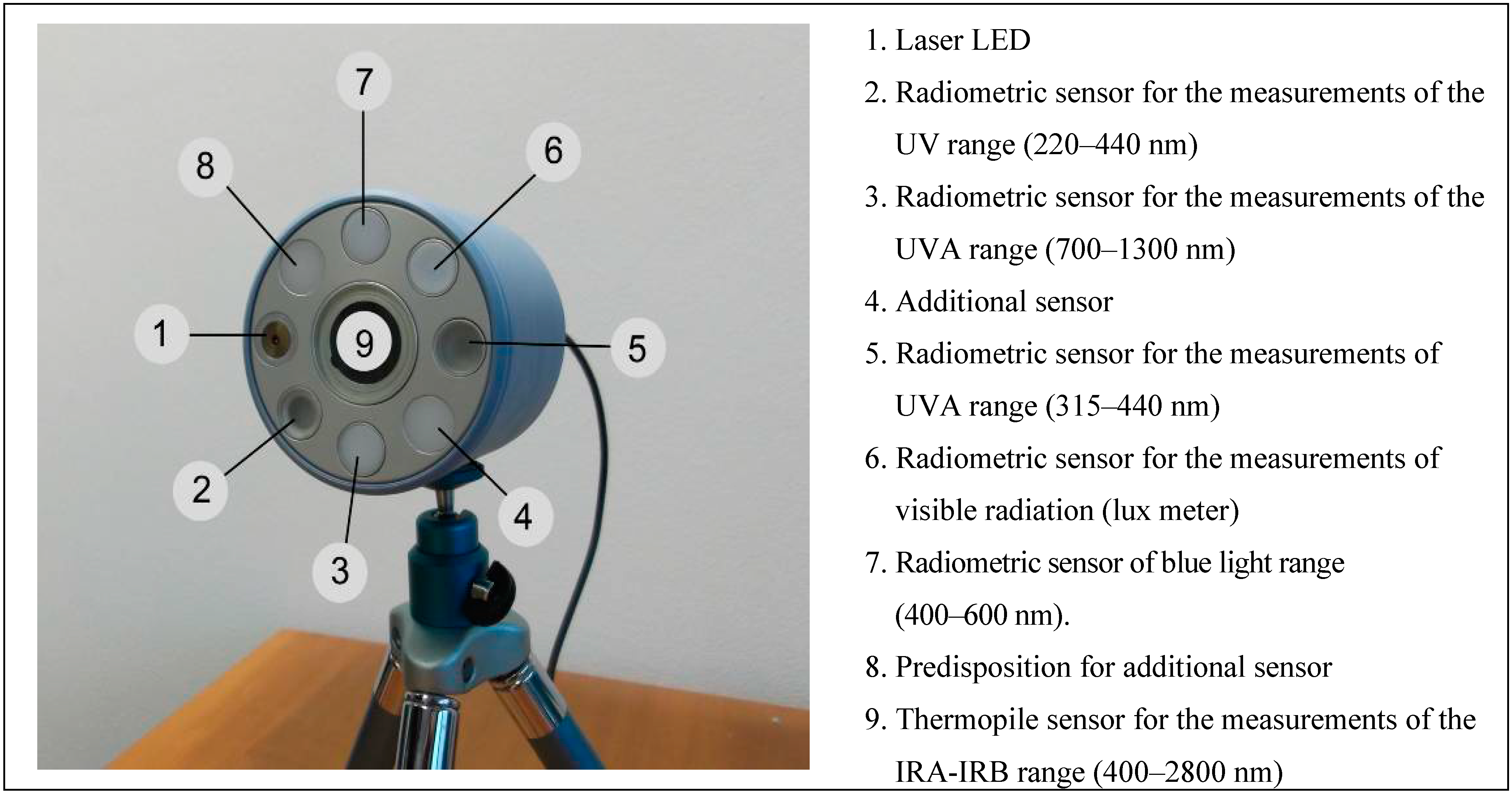
The AOR measurements were realized using a Delta Ohm HD2402 broadband photoradiometer [
24], with six integrated sensors (
Figure 1). The instrument used is a radiometer with a spectral sensitivity in accordance to the specific weighting functions S(λ), B(λ) and R(λ).
Each of the six sensors measures in a specific wavelength interval between the ultraviolet (UV) and infrared (IR) range. The sensors are the following: a radiometric sensor for UV (220–400 nm) corrected with the spectral weighting factor S(λ); a radiometric sensor for UVA (315–400 nm); a photometric sensor for the illumination in the visible range (380–780 nm); a radiometric sensor for the blue light (400–700 nm) corrected with the spectral weighting factor B(λ); a radiometric sensor for IR (700–1300 nm) corrected with the spectral weighting factor R(λ); a thermopile sensor to measure in the visible, IRA and IRB range (400–2800 nm). The circular position of the sensors and the presence of the integrated laser pointer, as demonstrated in
Figure 1 [
25], allow orientating the instrument correctly toward the source. The radiometric parameter measured by the HD2402 instrument is always irradiance (or illuminance as concerns Sensor 6 in
Figure 1); however, the radiance and the irradiance are related, and radiance can be obtained from irradiance (assuming that radiance is constant), provided that the geometric parameters of the measured source are known [
26,
27].
This instrument is of practical use to obtain, with a single device, radiometric measurements of the interesting parameters for each hazard as required by the EN 62471 [
17] and indicated in
Table 3.
Figure 1.
Delta Ohm HD2402 photoradiometer [
25].
Figure 1.
Delta Ohm HD2402 photoradiometer [
25].
4.2. Conditions of the Measurements
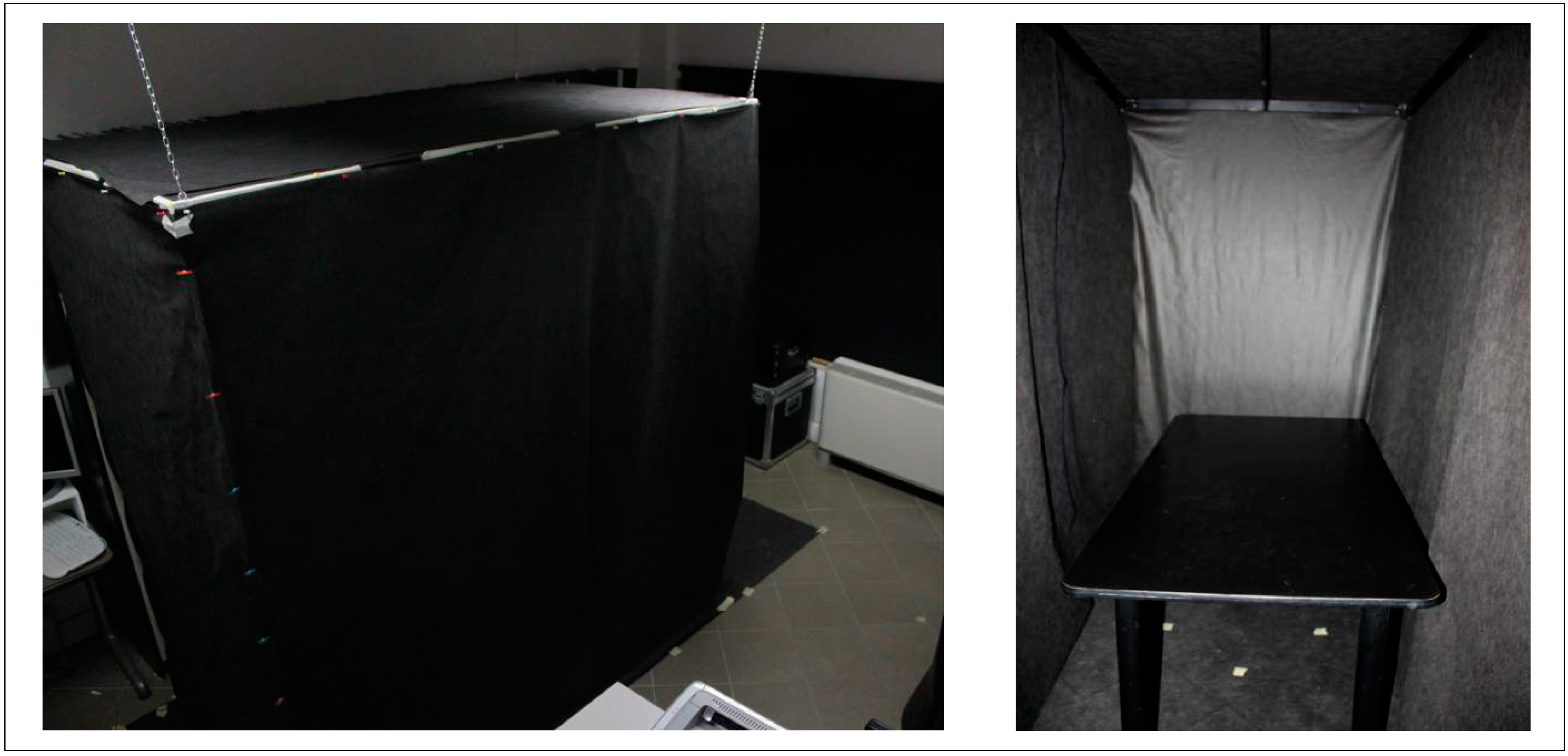
The measurements have been carried out in the Lighting and Acoustic Laboratory of the University of Pisa, where a suitable test chamber was realized, with the following dimensions: width 1.20 m, length 2.00 m, height 2.10 m (
Figure 2). This test chamber was constructed with a frame hanging from the ceiling on which a black fabric is fixed. The fabric is matt black (reflection factor 0.10) to create an environment in which the contribution of the reflected light is negligible. The shades of the windows of the room were completely shut to avoid the influence of the variability of daylight.
Each measurement had a duration of five minutes. Before measuring, the warm up time was respected (5–15 min, depending on the source type), so the examined sources had time to reach their regime state. The measurements have been performed at a distance of the source to detectors that produces an illuminance of 500 lx, as indicated in EN 62471 [
17] for lamps intended for general lighting service (GLS). The measurements have been repeated at distances source to detectors equal to 0.2 m and 1.0 m in order to have a better characterization of the emission of each source [
6,
18].
4.3. Post-Processing Data
The post-processing of the irradiance measurements has been performed using the software DeltaLog13 [
25], provided together with the instrument. This software permits one to visualize in real time the results of the measurements and to process the results saved on the instrument. With this post-processing software, it is possible to obtain the necessary values for the illuminance, the luminance, the irradiance and the radiance in the wavelength ranges of interest (see
Table 1).
Figure 2.
Test chamber: external view (left) and internal view (right).
Figure 2.
Test chamber: external view (left) and internal view (right).
As stated previously, the analysis of this study is focused particularly on the blue light range (300–700 nm), as this range is the most significant in the case of lamps with phosphor-based LEDs. These LEDs have generally a large emission in the interval of the Blue Light (as shown in the upper part of
Table 7), and therefore, an accurate evaluation of their emission is important, as in the classification of the photobiological safety.
For the completeness of the study, the results of the measurements at the source to detector distances of 0.2 m and 1.0 m are used to verify the risk of exposure according to what was provided in [
5,
19].
Concerning the verification of the risks of exposure for the workers, it is important to notice that it is difficult to meet the conditions of an exposure analogue to those in the test (at a distance of 0.2 m and 1.0 m with a viewing direction orthogonal to the source). These test conditions result in a more severe situation than usual working activities. Consequently, obtaining a low risk of exposure in the test conditions guarantees a low risk of exposure in the working conditions, except for particular and infrequent cases (e.g., maintenance work on the devices with the light source on).
5. AOR Measurements Results
The following results of the AOR measurements have been divided in groups according to the type of source (LED tube or fluorescent lamp) and color temperature (3000 K, 4000 K or 6000 K). For each group and each distance, the limit value, the median and the standard deviation of the radiance are represented in the blue light range (300–700 nm). Additionally, the obtained results are displayed for every single LED tube of 4000 K.
5.1. LED Tubes
The results of the measurements of all of the 48 analyzed 8 W LED tubes (16 for each color temperature) are shown in
Table 8. In this table, the following values are indicated: the observation distance, the angular dimension of the sources (α), the limit value (L
Blim) of the radiance and the median (M) and the standard deviation (SD) of the measured values.
In
Table 9, the results of the AOR measurements of each of the sixteen 8 W LED tubes (named: S1, S2, S3, ......, and S16) for the color temperature of 4000 K are shown in detail. For the evaluation of the results, it must be observed that for the range 300–700 nm (blue light range), the limit value of the radiance is 100 W/m
2sr (see
Section 2).
Table 8.
Results of AOR measurements on 8 W LED tubes.
Table 8.
Results of AOR measurements on 8 W LED tubes.
| Distance (cm) | Tk (K) | α (mrad) | LB (W/m2sr) 300–700 nm |
|---|
| LBlim | M | SD |
|---|
| 20 | 3000 | - | - | 83.31 | 4.70 |
| 4000 | 99.96 | 100 | 96.64 | 5.37 |
| 6000 | - | - | 231.25 | 2.50 |
| 60 (500 lx) | 3000 | - | - | 19.62 | 0.86 |
| 4000 | 65 | 100 | 31.19 | 1.01 |
| 6000 | - | - | 48.29 | 1.25 |
| 100 | 3000 | - | - | 7.15 | 0.68 |
| 4000 | 60 | 100 | 15.20 | 0.39 |
| 6000 | - | - | 19.87 | 0.83 |
Table 9.
Results of AOR measurements on 8 W LED tubes for 4000 K.
Table 9.
Results of AOR measurements on 8 W LED tubes for 4000 K.
| Distance (cm) | Lamps | LB (W/m2sr)
300–700 nm | Lamps | LB (W/m2sr)
300–700 nm | Lamps | LB (W/m2sr)
300–700 nm | Lamps | LB (W/m2sr)
300–700 nm |
|---|
| 20 | S1 | 85.64 | S5 | 96.61 | S9 | 112.2 | S13 | 96.01 |
| 60 (500 lx) | 31.61 | 30.01 | 31.20 | 32.61 |
| 100 | 11.27 | 11.98 | 12.53 | 12.25 |
| 20 | S2 | 96.66 | S6 | 84.84 | S10 | 93.74 | S14 | 96.54 |
| 60 (500 lx) | 32.21 | 31.55 | 29.98 | 30.83 |
| 100 | 11.43 | 11.67 | 11.31 | 12.23 |
| 20 | S3 | 98.35 | S7 | 97.70 | S11 | 97.03 | S15 | 88.92 |
| 60 (500 lx) | 29.77 | 30.17 | 32.01 | 31.12 |
| 100 | 12.28 | 12.14 | 11.75 | 11.66 |
| 20 | S4 | 98.34 | S8 | 100.5 | S12 | 96.31 | S16 | 98.72 |
| 60 (500 lx) | 33.63 | 31.59 | 30.77 | 31.17 |
| 100 | 11.89 | 11.97 | 12.09 | 12.58 |
5.2. Fluorescent Lamps
The results of the measurements of all of the 48 analyzed 18 W fluorescent lamps (16 for each color temperature) are shown in
Table 10. In this table, similar to the LED tubes, are indicated: the observation distance, the angular dimension of the sources (α), the limit value (L
Blim) of the radiance and the median (M) and the standard deviation (SD) of the measured values.
6. Discussion of the Measurements Results
The results of the measurements of the AOR are discussed below in relation to the photobiological safety of the lamps with the resulting classification in risk groups. The discussion is completed with the evaluation of the risk of exposure, according to the provided European and National legislation (see
Section 2).
Table 10.
Results of AOR measurements on 18 W fluorescent lamps.
Table 10.
Results of AOR measurements on 18 W fluorescent lamps.
| Distance (cm) | Tk (K) | α (mrad) | LB (W/m2sr) 300–700 nm |
|---|
| LBlim | M | SD |
|---|
| 20 | 3000 | - | - | 35.00 | 0.78 |
| 4000 | 99.96 | 100 | 123.65 | 1.39 |
| 6000 | - | - | 139.00 | 1.62 |
| 50 (500 lx) | 3000 | - | - | 15.59 | 1.06 |
| 4000 | 61.1 | 100 | 32.49 | 1.53 |
| 6000 | - | - | 51.45 | 2.15 |
| 100 | 3000 | - | - | 5.80 | 0.42 |
| 4000 | 60 | 100 | 9.75 | 0.59 |
| 6000 | - | - | 14.70 | 0.99 |
It can be observed immediately that the distance at which the illuminance of the LED tubes reaches 500 lx is 0.60 m, and for the fluorescent lamps, this is 0.50 m. This can prompt questions, since the luminous flux of the LED tubes is 900 lm, and for the fluorescent lamps, it is 1350 lm. However, this can be explained by the fact that the angle of the light beam of the LEDs is 120° and of the fluorescent lamps 360°, and thus, the beam of the LED tubes is more concentrated.
6.1. Maximum Permissible Exposure Time and Risk Group Classification According to EN 62471
The risk group classification for the analyzed sources has been performed based on the radiance L
B (W/m
2sr), which is the radiance emitted in the wavelength interval 300–700 nm (the blue light range). In
Table 11, the risk group (RG) and the t
max for each analyzed lamp are reported (calculated with the median radiance value; see
Table 8 and
Table 10). From these values, it can be noticed that the LED tube of 6000 K and fluorescent lamps of 4000 K and 6000 K are classified as RG1, with a t
max of 4324 s (1 h 12 min), 8087 s (2 h 15 min) and 7194 s (2 h), respectively. The other lamps (LED tube 3000 K and 4000 K, fluorescent lamp 3000 K) are classified as RG0. However, there are two lamps, S8 and S9 (see
Table 12), in the group of LED tubes with a color temperature of 4000 K that have an L
B value higher than the limit of 100 W/m
2sr and, thus, a t
max lower than 10,000 s (2 h 47 min): 9951 s (2 h 45 min) and 8909 s (2 h 28 min), respectively. Therefore, those two must be classified as RG1; see also
Table 12.
Table 11.
Risk group classification of the analyzed lamps at a distance of 0.20 m.
Table 11.
Risk group classification of the analyzed lamps at a distance of 0.20 m.
| Lamps | LB (W/m2sr) | tmax (s) | RG |
|---|
| LED tubes 3000 K | 83.31 | >10,000 | 0 |
| LED tubes 4000 K | 96.64 | >10,000 | 0 |
| LED tubes 6000 K | 231.25 | 4324 | 1 |
| Fluorescent lamps 3000 K | 35.00 | >10,000 | 0 |
| Fluorescent lamps 4000 K | 123.65 | 8087 | 1 |
| Fluorescent lamps 6000 K | 139.00 | 7194 | 1 |
Table 12.
Risk group classification and maximum permissible exposure time of the LED tubes 4000 K at a distance of 0.20 m.
Table 12.
Risk group classification and maximum permissible exposure time of the LED tubes 4000 K at a distance of 0.20 m.
| Lamps | LB (W/m2sr) | tmax (s) | RG | Lamps | LB (W/m2sr) | tmax (s) | RG |
|---|
| S1 | 85.64 | >10,000 | 0 | S9 | 112.2 | 8909 | 1 |
| S2 | 96.66 | >10,000 | 0 | S10 | 93.74 | >10,000 | 0 |
| S3 | 98.35 | >10,000 | 0 | S11 | 97.03 | >10,000 | 0 |
| S4 | 98.34 | >10,000 | 0 | S12 | 96.31 | >10,000 | 0 |
| S5 | 96.61 | >10,000 | 0 | S13 | 96.01 | >10,000 | 0 |
| S6 | 84.84 | >10,000 | 0 | S14 | 96.54 | >10,000 | 0 |
| S7 | 97.70 | >10,000 | 0 | S15 | 88.92 | >10,000 | 0 |
| S8 | 100.5 | 9951 | 1 | S16 | 98.72 | >10,000 | 0 |
6.2. Risk of Exposure to AOR According to Directive 2006/25/EC
From the results of the AOR measurements on the LED tubes shown in
Table 8, it can be noticed that the only LED tubes with a median radiance value higher than the limit value (L
B = 100 W/m
2sr) are those with a color temperature of 6000 K, measured at a distance of 0.20 m. However, the values in
Table 9 show that in the group of LED tubes of 4000 K, there are two lamps, S8 and S9, with a radiance value higher than the limit: 100.5 W/m
2sr and 112.2 W/m
2sr, respectively. These results are not perceptible only out of the median value.
The only fluorescent lamps with a median radiance value higher than the limit value (LB = 100 W/m2sr) are those with a color temperature of 4000 K and 6000 K, measured at a distance of 0.20 m.
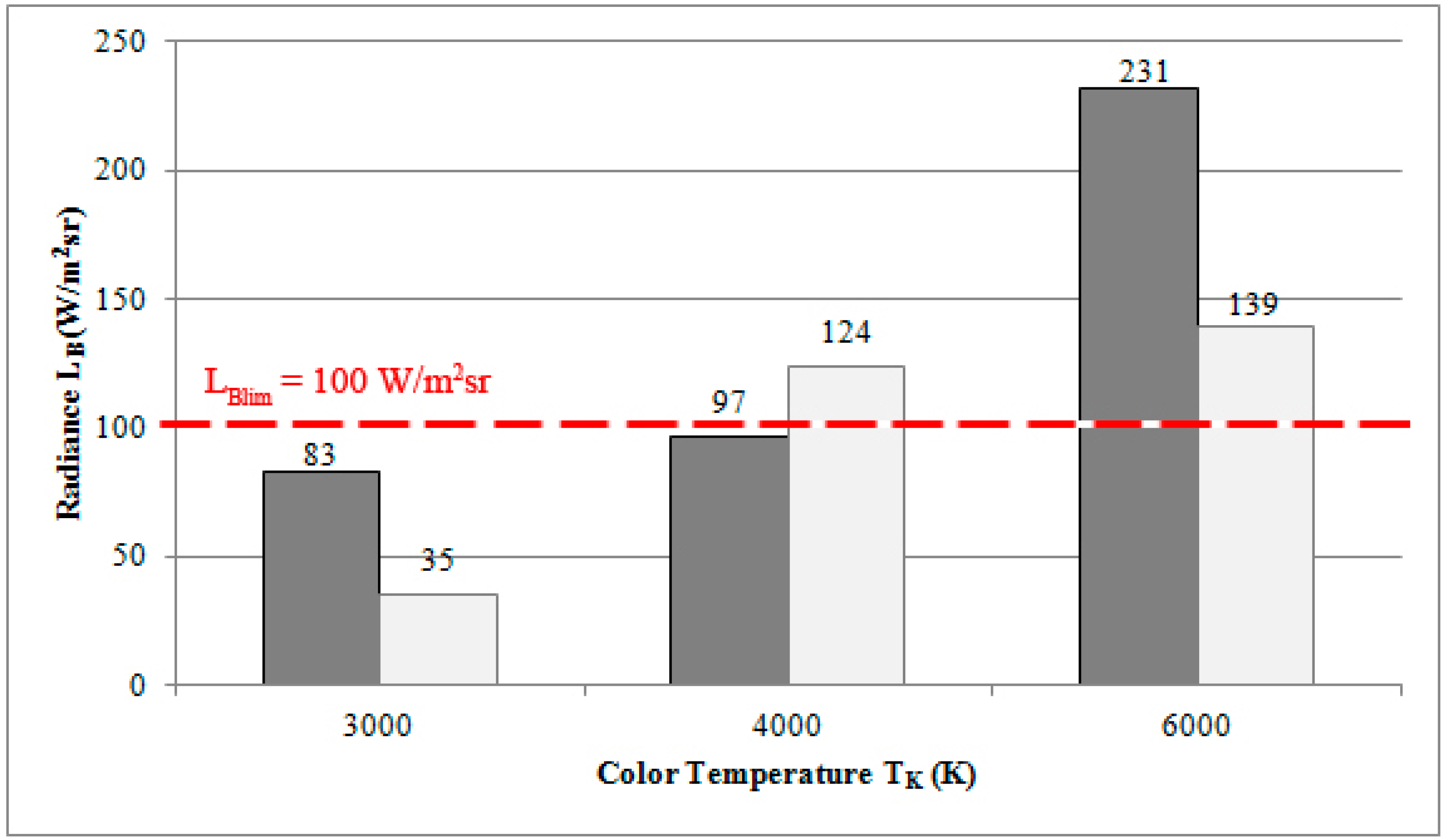
In
Figure 3, the median radiance values for L
B, measured at a distance of 0.20 m, of all of the types of lamps are set side by side. It is clear that the radiance values increase with the color temperature, and at 4000 K, the radiance of both LED tubes and fluorescent lamps is near the limit value.
Figure 3.
Comparison of the radiance LB in the blue light range between the LED tubes (dark gray) and the fluorescent lamps (light gray) with different color temperatures at a distance of 0.20 m.
Figure 3.
Comparison of the radiance LB in the blue light range between the LED tubes (dark gray) and the fluorescent lamps (light gray) with different color temperatures at a distance of 0.20 m.
7. Conclusions
In spite of the problem of the risk assessment from exposure to AOR having long been analyzed, there are always new light sources available on the market, whose photobiological safety must be analyzed.
In this paper, the authors have shown and discussed the results of a measurement survey of AOR emitted by 8 W LED tubes, which are suitable for the substitution of 18 W fluorescent lamps.
In a wide range of wavelengths (180–3000 nm), the irradiance values measured and the radiance values calculated have been analyzed as required in the EU Directive 2006/25, and a risk group according to the EN 62471 has been attributed to each LED tube.
From the measurement results, considering in particular the average values of the radiance, it is possible to highlight that only the LED tubes with a color temperature of 6000 K are in Risk Group 1 (low risk); on the contrary, all of the other LED tubes are in Risk Group 0 (exempt risk). For the LED tubes with a color temperature of 6000 K, the maximum permissible exposure time is however still very high, approximately 4300 s.
By comparison, the AOR emission analysis was also performed for the fluorescent lamps, which could be replaced with the examined LED tubes. In this case, the fluorescent lamps of 4000 K and 6000 K are classified in Risk Group 1 (low risk) and the fluorescent lamps of 3000 K in Risk Group 0 (exempt risk). The fluorescent lamps of 4000 K and 6000 K have a maximum permissible exposure times of 8100 s and 7200 s, respectively.
Although not generally harmful to health, the new LED sources, which are continuously inserted into the market, require an accurate analysis of their emissions and a classification according to the risk groups defined in the EN 62471 in order to make both installers and users aware of the safe manners of exposition and about the maximum permissible exposure times to these sources.


