
Natural and Artificial Methods for Regeneration of Heat Resources for Borehole Heat Exchangers to Enhance the Sustainability of Underground Thermal Storages: A Review


Abstract
:1. Introduction


2. Approach and Methodology
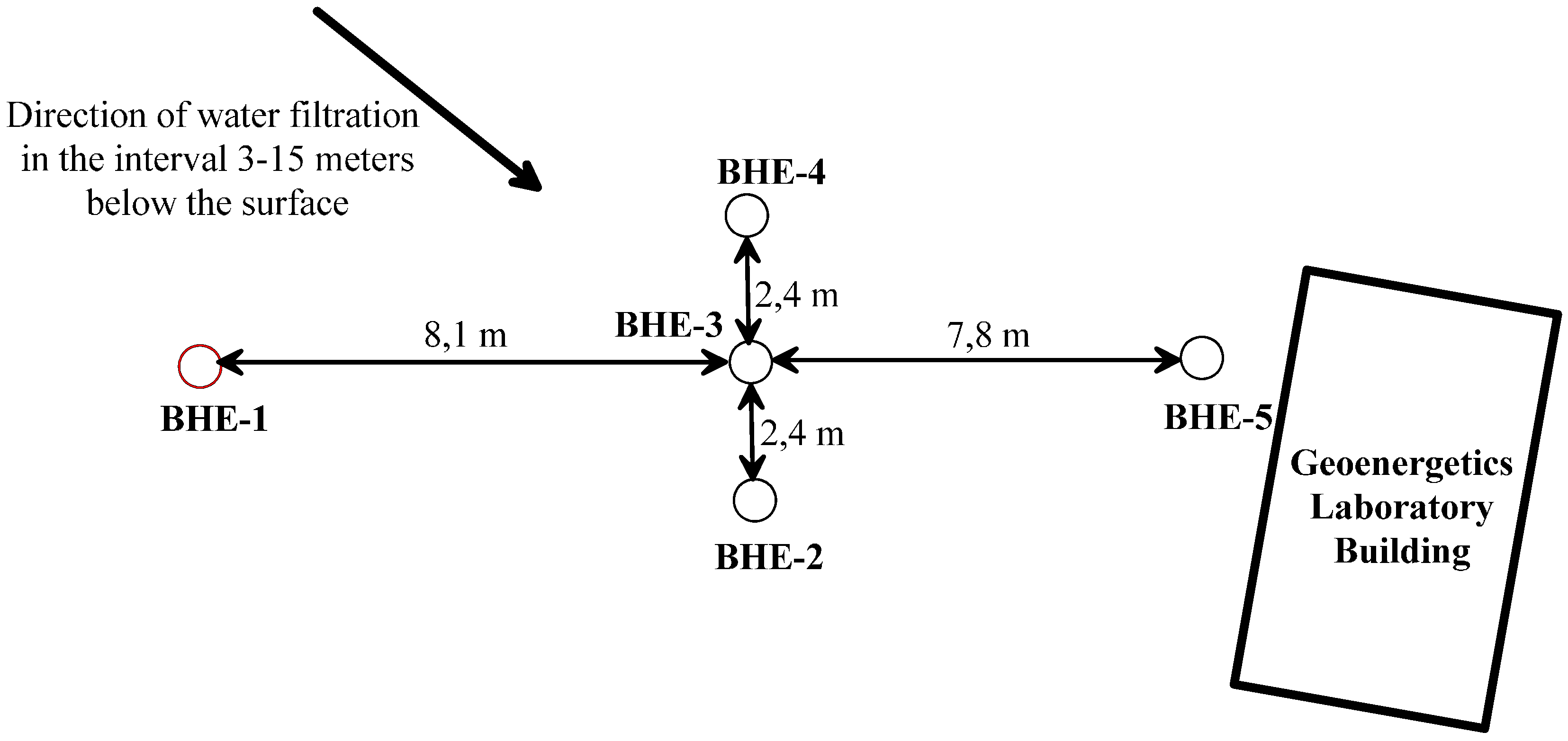
2.1. Geoenergetics Laboratory


| No. | Parameter | Pictorial Configuration | Value | ||||
|---|---|---|---|---|---|---|---|
| LG 1 (BHE 1) | LG 2 (BHE 2) | LG 3 (BHE 3) | LG 4 (BHE 4) | LG 5 (BHE 5) | |||
| 1 | Depth of borehole | - | 78 m | 82 m | 78 m | 78 m | 78 m |
| 2 | Depth at which exchanger’s tubes are seated | 78 m | |||||
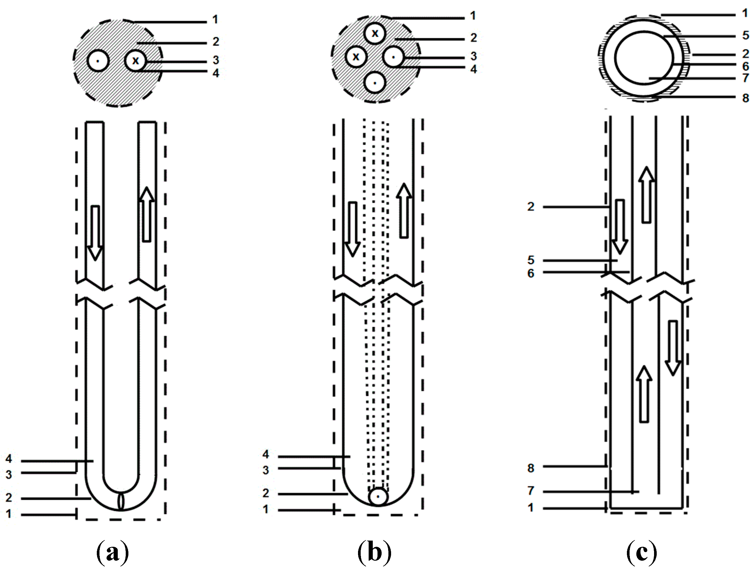
| 3 | Design of borehole heat exchanger | - |  |  |  | ||
| 4 | Borehole diameter Do (drill tool diameter) |  | 143 mm | ||||
| 5 | Distance between tubes in heat exchanger, k |  | n/a | 80 mm | n/a | ||
| 5` | Distance between tubes in heat exchanger, k | 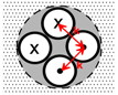 | n/a | n/a | 70 mm | ||
| 6 | Material used for sealing heat exchanger (grout) |  | cement, λ = 1.2 Wm−1·K−1 | cement, λ = 1.2 Wm−1·K−1 | Thermocem, increased thermal conductivity cement, λ = 2.0 Wm−1·K−1 | Gravel 8–16 mm of grain and clayey plugs, λ = 1.8 Wm−1·K−1 | cement, λ = 1.2 Wm−1·K−1 |
| 7 | Outer diameter of tubes in heat exchanger | 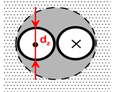 | n/a | 40 mm | 32 mm | ||
| 7` | Outer diameter of outer tubes in heat exchanger |  | 90 mm | n/a | |||
| 7`` | Outer diameter of inner tubes in heat exchanger |  | 40 mm | n/a | |||
| 8 | Thickness of tube wall in heat exchanger | 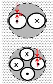 | n/a | 2.4 mm | 2.4 mm | ||
| 8` | Thickness of outer tube wall in heat exchanger | 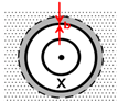 | 5.4 mm | n/a | |||
| 8`` | Thickness of inner tube wall in heat exchanger | 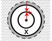 | 2.4 mm | n/a | |||
| 9 | Material of tubes in heat exchanger | 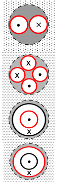 | Polyethylene, λ = 0.42 Wm−1·K−1 | ||||
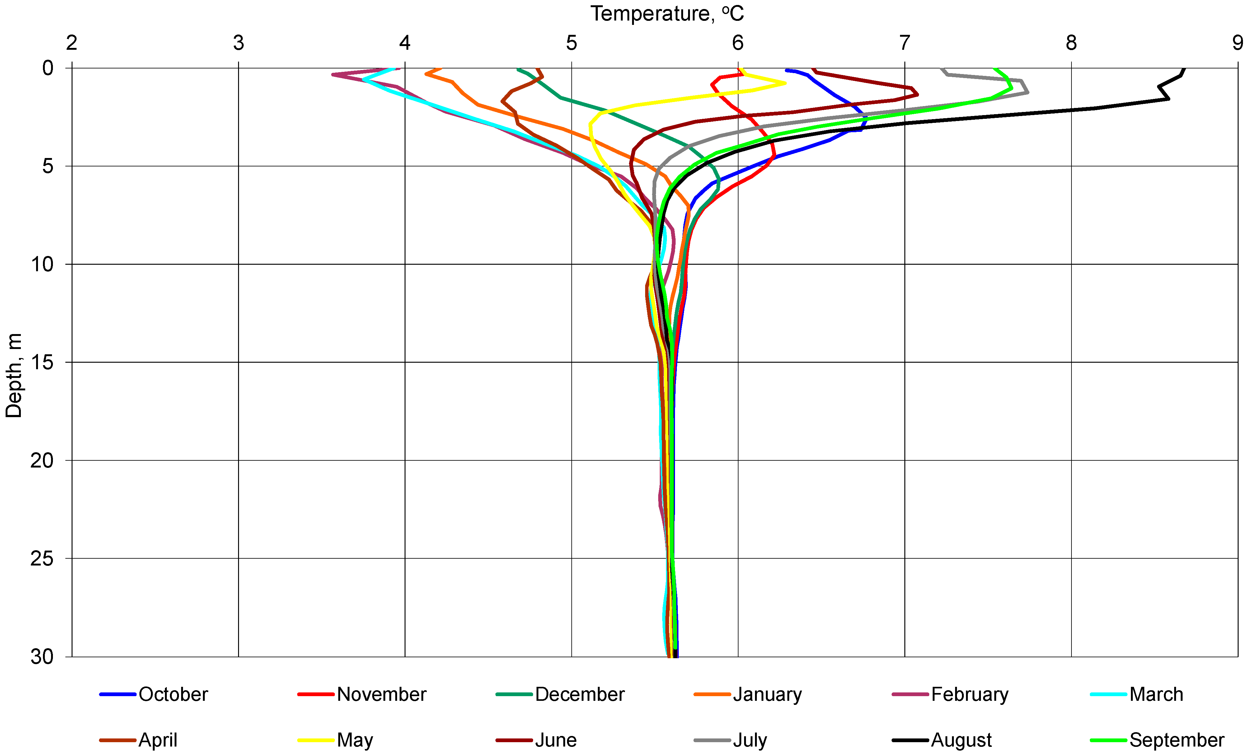
2.2. Ground Characteristics at Test Site
| No. | Top, m | Bottom, m | Thickness, m | Lithology | Stratigraphy | Thermal Conductivity, λ, W·m−1·K−1 | Volumetric Specific Heat, cv, MJ·m−3·K−1 |
|---|---|---|---|---|---|---|---|
| 1 | 0.0 | 2.2 | 2.2 | Anthropogenic ground (dark grey fill with debris) | Quaternary (Pleistocene, Holocene) | 1.600 | 2.000 |
| 2 | 2.2 | 2.6 | 0.4 | Aggregate mud (grey ground) | 1.600 | 2.200 | |
| 3 | 2.6 | 4.0 | 1.4 | Fine, dusty and slightly clayey sand | 1.000 | 2.000 | |
| 4 | 4.0 | 6.0 | 2.0 | Fine sand | 1.200 | 2.500 | |
| 5 | 6.0 | 15.0 | 9.0 | Sand and slag mix, slag | 1.800 | 2.400 | |
| 6 | 15.0 | 30.0 | 15.0 | Grey clay | Tertiary (Miocene) | 2.200 | 2.300 |
| 7 | 30.0 | 78.0 | 48.0 | Gray clay slate | 2.100 | 2.300 | |
| Weighted average | 2.039 | 2.309 | |||||

2.3. Experimental Capability and Measurable Quantities
- (1)
- A heating-cooling system for the Faculty Auditorium, which has a seating capacity of 160
- (2)
- Solar collectors for regeneration of heat in the rock mass, with individual measurement sensors
- (3)
- A system for snow melting of the parking lot in front of the Laboratory
- (4)
- A fan for heating and cooling glycol using atmospheric air
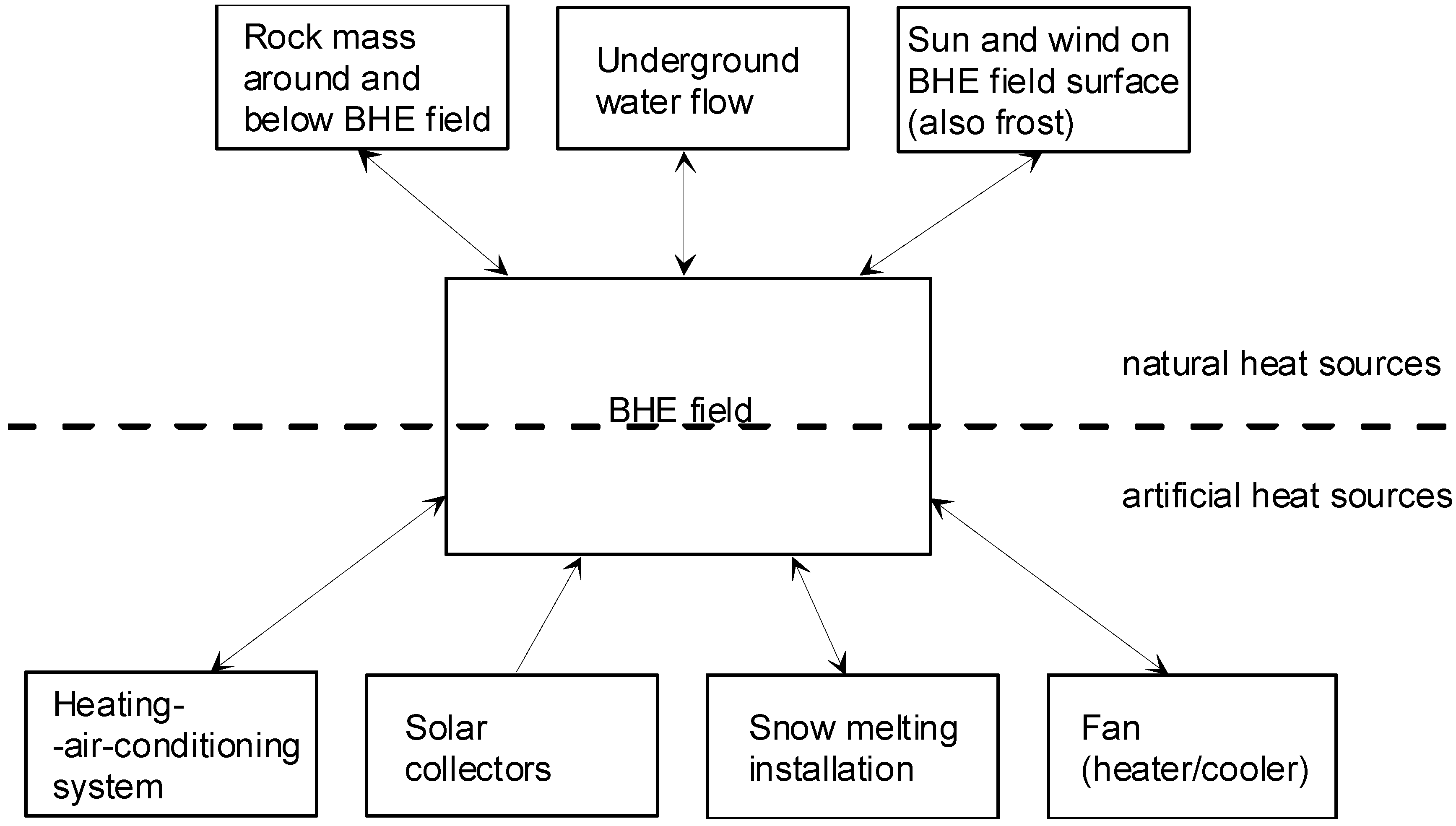
| No. | Natural Heat Sources for Regeneration BHE of Field | Artificial Heat Sources for Regeneration BHE of Field |
|---|---|---|
| 1 | Underground water flow | Heating-air-conditioning system of Auditorium |
| 2 | Sun operation on surface (also wind and frost) | Solar collectors |
| 3 | Heat transfer from the sides of the BHE space | Snow melting installation |
| 4 | Heat transfer from the bottom of the BHE space | Fan (heater/cooler) |
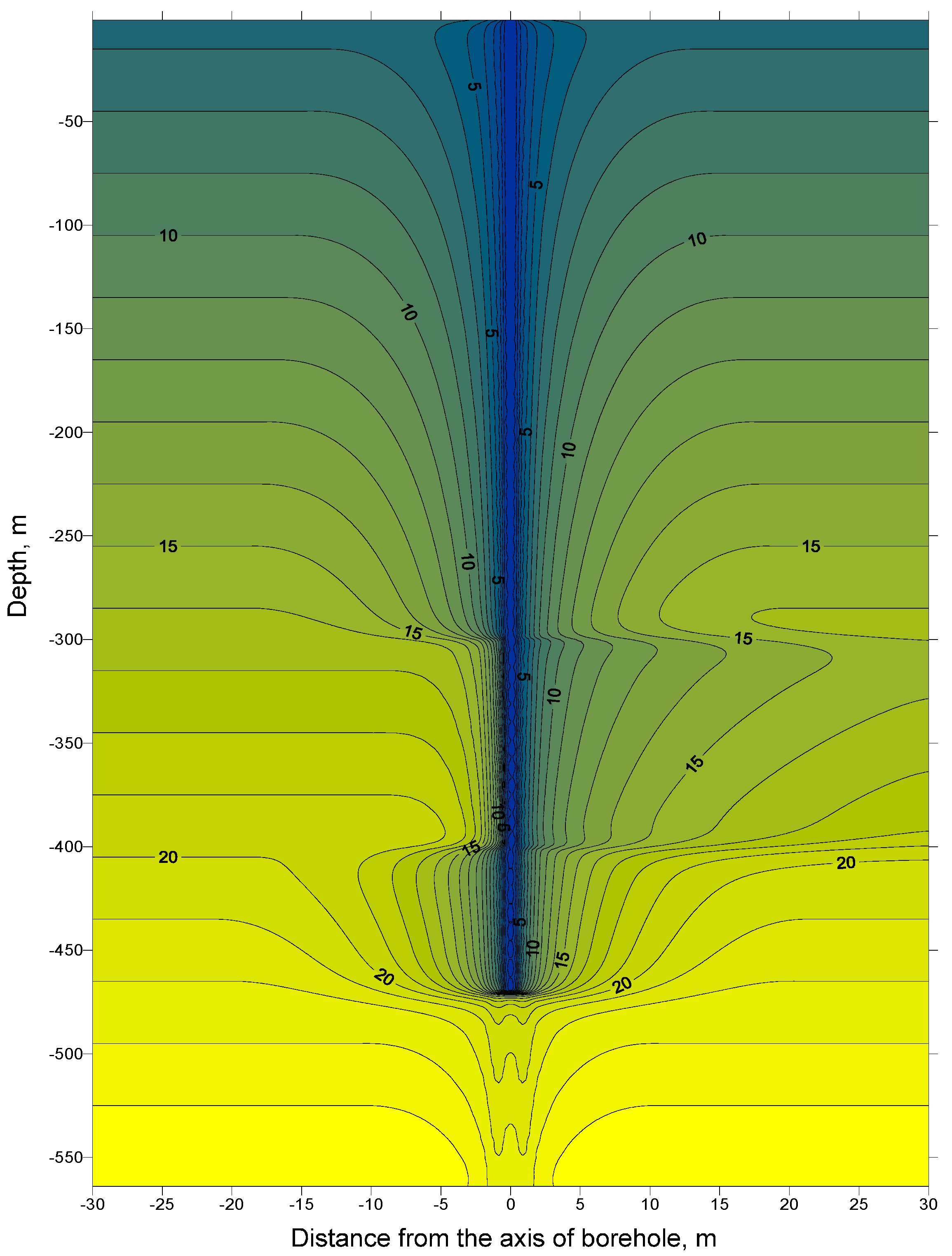
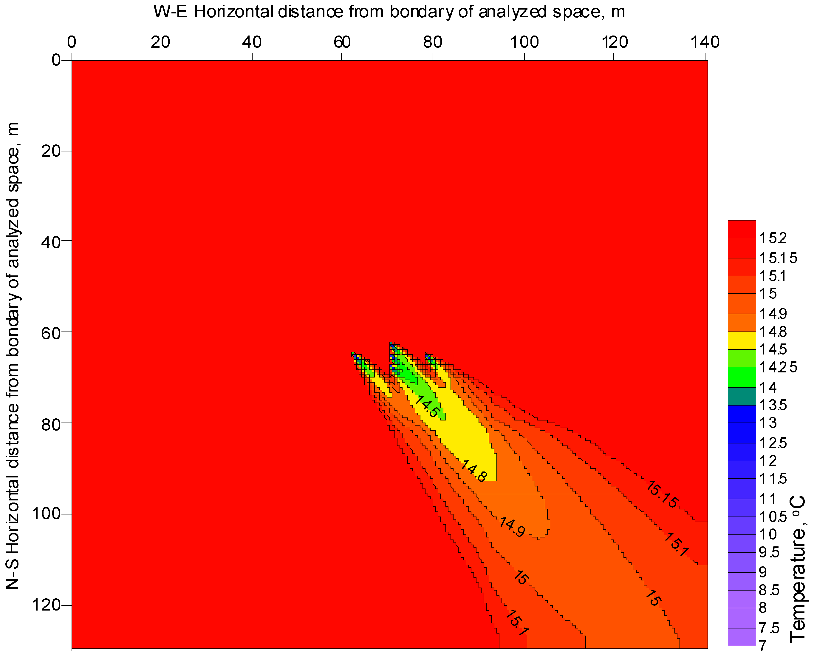
3. Natural Heat Resources Regeneration


4. Artificial Heat Resources Regeneration
4.1. Heating/Air-Conditioning System of the Auditorium
4.2. Solar Collectors
4.3. Snow Melting Installation
4.4. Fan (Heater/Cooler)
4.5. Further Discussion
5. Conclusions
- (1)
- Natural ways of heat regeneration can permit full or partial temperature restoration. For supplemented heat resources, when natural full renewability is not possible but necessary (or advantageous), artificial sources of heat can be used.
- (2)
- In real projects, it is necessary to take into consideration all possible options for obtaining heat. Sometimes it is possible to obtain a low-temperature heat flux from other sources, such as waste heat.
- (3)
- Nowadays designers should analyze all energetic aspects of buildings and other structures as well as the neighborhood of designed projects.
- (4)
- BHE fields can be effectively used for energy storage. This is particularly important for renewable energy sources, which are often characterized by intermittency (like wind energy for example). Energy storage also enables greater use of distributed energy sources.
- (5)
- Natural heat regeneration options for BHEs storages are sun, wind, surrounding rocks and underground water. Artificial options that can be used include solar heat using, for example, air-conditioning installations, solar collectors, fans, snow melting installations working in reverse mode and waste heat from industry.
| No. | Heat Source | Origin | Comments |
|---|---|---|---|
| 1 | Underground water flow | Natural | Positive in the case of heating and cooling systems with deficit of heat or cool. Negative when storing heat or cool. |
| 2 | Solar energy incidence on surface (wind and frost also) | Natural | Heat gain positive when heat deficit/storage. Heat loss positive when cold deficit/storage. |
| 3 | Heat transfer from the sides of the BHE space | Natural | Positive when heat deficit. Negative when cold storage. |
| 4 | Heat transfer from the bottom of the BHE space | Natural | Positive when heat deficit. Negative when cold storage. |
| 5 | Heating-air-conditioning system of Auditorium | Artificial, need extra installation | Should be used in both directions of heat transfer when possible. |
| 6 | Solar collectors | Artificial, need extra installation | Can be used only for heat recovery when heat deficit in annual balance or for heat storage. |
| 7 | Snow melting installation | Artificial, need extra installation | In reverse mode can be used as a heat source when there is a deficit of heat. |
| 8 | Fan (heater/cooler) | Artificial, need extra installation | Can be used in the case of deficit of heat or cool in annual balance. Can be used for heat or cool storage. |
Acknowledgments
Author Contributions
Conflicts of Interest
References
- Tomaszewska, B.; Pająk, L. Geothermal water resources management-economic aspects of their treatment. Miner. Resour. Manag. (Gospodarka Surowcami Mineralnymi) 2012, 28, 59–70. Available online: https://www.min-pan.krakow.pl/Wydawnictwa/GSM284/tomaszewska-pajak.pdf (accessed on 24 August 2015). [Google Scholar]
- Sapinska-Sliwa, A.; Rosen, M.A.; Gonet, A.; Sliwa, T. Deep Borehole Heat Exchangers: A Conceptual Review. In Proceedings of the World Geothermal Congress 2015, Melbourne, Australia, 19–25 April 2015; pp. 1–11. Available online: http://www.geothermal-energy.org/pdf/IGAstandard/WGC/2015/28045.pdf? (accessed on 24 August 2015).
- Sliwa, T.; Gonet, A. The closing wells as heat source. Acta Montan. Slovaca 2004, 9, 300–302. Available online: http://actamont.tuke.sk/pdf/2004/n3/37sliwa.pdf (accessed on 24 August 2015). [Google Scholar]
- Gonet, A.; Sliwa, T.; Stryczek, S.; Sapinska-Sliwa, A.; Jaszczur, M.; Pająk, L.; Złotkowski, A. Metodyka Identyfikacji Potencjału Cieplnego Górotworu wraz z Technologią Wykonywania i Eksploatacji Otworowych Wymienników Ciepła (Methodology for the Identification of Potential Heat of the Rock Mass Along with Technology Implementation and Operation of Borehole Heat Exchangers); AGH University of Science and Technology Press: Krakow, Poland, 2011; p. 439. (In Polish) [Google Scholar]
- Signorelli, S.; Kohl, T.; Rybach, L. Sustainability of Production from Borehole Heat Exchanger Fields. In Proceedings of the World Geothermal Congress 2005, Antalya, Turkey, 26–28 January 2005; pp. 1–6. Available online: http://www.geothermal-energy.org/pdf/IGAstandard/WGC/2005/1450.pdf? (accessed on 8 September 2015).
- Jaszczur, M.; Śliwa, T. The analysis of long-term borehole heat exchanger system exploitation. CAMES 2013, 20, 227–235. Available online: http://cames.ippt.gov.pl/pdf/CAMES_20_3_6.pdf (accessed on 24 August 2015). [Google Scholar]
- Blomberg, T.; Claesson, J.; Eskilson, P.; Hellström, G.; Sanner, B. Earth Energy Designer (EED 3.16), Software within Building Physics and Ground Heat Storage. Available online: http://www.buildingphysics.com/manuals/EED3.pdf (accessed on 24 August 2015).
- Nordell, B. Borehole Heat Store Design Optimization. Ph.D. Thesis, Division of Water Resources Engineering, Luleå University of Technology, Luleå, Sweden, 1994; p. 217. Available online: http://www.ltu.se/cms_fs/1.5013!/file/FINAL_NORDELL_PHD_red.pdf (accessed on 24 August 2015). [Google Scholar]
- Bujok, P.; Klempa, M.; Koziorek, J.; Rado, R.; Porzer, M. Ocena Wpływu Warunków Klimatycznych na Bilans Energetyczny Górotworu na Obszarze Poligonu Badawczego VSB—TU Ostrava. Available online: http://journals.bg.agh.edu.pl/DRILLING/2012-01/W_2012_1_07.pdf (accessed on 22 September 2015). (In Polish)
- Koohi-Fayegh, S.; Rosen, M.A. Examination of thermal interaction of multiple vertical ground heat exchangers. Appl. Energy 2012, 97, 962–969. [Google Scholar] [CrossRef]
- Gehlin, S.; Andersson, O.; Bjelm, L.; Alm, P.G.; Rosberg, J.E. Country Update for Sweden. In Proceedings of the World Geothermal Congress 2015, Melbourne, Australia, 19–25 April 2015; Available online: https://pangea.stanford.edu/ERE/db/WGC/papers/WGC/2015/01021.pdf (accessed on 8 September 2015).
- Rybach, L.; Eugster, W.J. Sustainability aspects of geothermal heat pump operation, with experience from Switzerland. Geothermics 2010, 39, 365–369. [Google Scholar] [CrossRef]
- Weber, J.; Ganz, B.; Schellschmidt, R.; Sanner, B.; Schulz, R. Geothermal Energy Use in Germany. In Proceedings of the World Geothermal Congress 2015, Melbourne, Australia, 19–25 April 2015; Available online: http://www.geothermal-energy.org/pdf/IGAstandard/WGC/2015/01045.pdf? (accessed on 24 August 2015).
- Raymond, J.; Malo, M.; Tanguay, D.; Grasby, S.; Bakhteyar, F. Direct Utilization of Geothermal Energy from Coast to Coast: A Review of Current Applications and Research in Canada. In Proceedings of the World Geothermal Congress 2015, Melbourne, Australia, 19–25 April 2015; Available online: http://www.geothermal-energy.org/pdf/IGAstandard/WGC/2015/28041.pdf? (accessed on 24 August 2015).
- Boyd, T.L.; Sifford, A.; Lund, J.W. The United States of America Country Update 2015. In Proceedings of the World Geothermal Congress 2015, Melbourne, Australia, 19–25 April 2015; pp. 1–12. Available online: http://www.geothermal-energy.org/pdf/IGAstandard/WGC/2015/01009.pdf? (accessed on 24 August 2015).
- Sasada, M. Geothermal Heat Pumps in Japan. Japan International Geothermal Symposium, Geothermal Research Society of Japan, Japan, 2012. Available online: http://www.geothermal-energy.org/pdf/IGAstandard/Japan/2012/p17-Masakatsu_Sasada(Eng-Jpn).pdf? (accessed on 8 September 2015).
- Lund, J.W.; Gawell, K.; Boyd, T.L.; Jennejohn, D. The United States of America Country Update 2010. In Proceedings of the World Geothermal Congress 2010, Bali, Indonesia, 25–29 April 2010; pp. 1–18. Available online: http://www.geothermal-energy.org/pdf/IGAstandard/WGC/2010/0102.pdf? (accessed on 24 August 2015).
- Lee, K.S. Underground Thermal Energy Storage; Springer Science & Business Media: Heidelberg, Germany, 2012; p. 152. [Google Scholar]
- Sliwa, T. Techniczno-ekonomiczne problemy adaptacji wykorzystanych odwiertów na otworowe wymienniki ciepła (Technical and Economic Problems of Adaptation of Used Wells into Borehole Heat Exchangers). Ph.D. Thesis, AGH University of Science and Technology in Krakow, Krakow, Poland, 2002; p. 128. [Google Scholar]
- Gonet, A.; Sliwa, T. Thermal Response Test on the Example of Borehole Heat Exchangers in Ecological Park Of Education and Amusement “OSSA”. Transport. Logist. 2008, 6, 42–47. [Google Scholar]
- Stryczek, S.; Wiśniowski, R.; Gonet, A.; Złotkowski, A.; Ziaja, J. Influence of polycarboxylate superplasticizers on rheological properties of cement slurries used in drilling technologies. Arch. Min. Sci. 2013, 58, 719–728. Available online: http://mining.archives.pl/index.php/index.php?option=com_remository&Itemid=0&func=fileinfo&id=645&lang=pl (accessed on 24 August 2015). [Google Scholar]
- Sliwa, T.; Knez, D.; Gonet, A.; Sapinska-Sliwa, A.; Szłapa, B. Research and Teaching Capacities of the Geoenergetics Laboratory at Drilling, Oil and Gas Faculty AGH University of Science and Technology in Kraków (Poland). In Proceedings of the World Geothermal Congress 2015, Melbourne, Australia, 19–25 April 2015; pp. 1–14. Available online: http://www.geothermal-energy.org/pdf/IGAstandard/WGC/2015/09012.pdf? (accessed on 24 August 2015).
- Sliwa, T.; Rosen, M.A.; Jezuit, Z. Use of oil boreholes in the Carpathians in geoenergetics systems historical and conceptual review. Res. J. Environ. Sci. 2014, 8, 231–242. Available online: http://scialert.net/qredirect.php?doi=rjes.2014.231.242&linkid=pdf (accessed on 24 August 2015). [Google Scholar] [CrossRef]
- Knez, D. Stress state analysis in aspect of wellbore drilling direction. Arch. Min. Sci. 2014, 59, 71–76. [Google Scholar] [CrossRef]
- Eskilson, P. Thermal Analyses of Heat Extraction Boreholes. Ph.D. Thesis, Department of Mathematical Physics, Lund Institute of Technology, Lund, Sweden, 1987. Available online: http://www.buildingphysics.com/Eskilson1987.pdf (accessed on 8 September 2015). [Google Scholar]
- Hellström, G. Ground Heat Storage, Thermal Analyses of Duct Storage Systems. Ph.D. Thesis, Department of Mathematical Physics, Lund Institute of Technology, Lund, Sweden, 24 May 1991. [Google Scholar]
- Kurevija, T.; Vulin, D.; Krapec, V. Influence of Undisturbed Ground Temperature and Geothermal Gradient on the Sizing of Borehole Heat Exchangers. In Proceedings of the World Renewable Energy Congress 2011, Linköping, Sweden, 8–13 May 2011; pp. 1360–1367. Available online: http://www.ep.liu.se/ecp/057/vol5/017/ecp57vol5_017.pdf (accessed on 8 September 2015).
- Cataldi, R. Sustainability and Renewability of Geothermal Energy. In Proceedings of the International Scientific Conference on Geothermal Energy in Underground Mines, Ustron, Poland, 21–23 November 2001; Available online: http://www.geothermal-energy.org/pdf/IGAstandard/Poland/2001/a4.pdf? (accessed on 24 August 2015).
- Signorelli, S.; Kohl, T.; Rybach, L. Sustainability of Production from Borehole Heat Exchanger Fields. In Proceedings of the Twenty-Ninth Workshop on Geothermal Reservoir Engineering, Stanford University, Stanford, CA, USA, 2004; pp. 1–6. Available online: http://www.geothermal-energy.org/pdf/IGAstandard/SGW/2004/Signorelli.pdf? (accessed on 24 August 2015).
- Dehkordi, E.; Schincariol, R.A. Effect of thermal-hydrogeological and borehole heat exchanger properties on performance and impact of vertical closed-loop geothermal heat pump systems. Hydrogeol. J. 2014, 22, 189–203. [Google Scholar] [CrossRef]
- Chiasson, A.C.; Rees, S.J.; Spitler, J.D. A preliminary assessment of the effects of ground-water flow on closed-loop ground-source heat pump systems. ASHRAE Trans. 2000, 106, 380–393. [Google Scholar]
- Diao, N.; Li, Q.; Fang, Z. Heat transfer in ground heat exchangers with groundwater advection. Int. J. Therm. Sci. 2004, 43, 1203–1211. [Google Scholar] [CrossRef]
- Fujii, H.; Itoi, R.; Fujii, J.; Uchida, Y. Optimizing the design of large-scale ground-coupled heat pump systems using groundwater and heat transport modelling. Geothermics 2005, 34, 347–364. [Google Scholar] [CrossRef]
- Hecht-Méndez, J.; de Paly, M.; Beck, M.; Bayer, P. Optimization of energy extraction for vertical closed-loop geothermal systems considering groundwater flow. Energy Convers. Manag. 2013, 66, 1–10. [Google Scholar] [CrossRef]
- Molina-Giraldo, N.; Blum, P.; Zhu, K.; Bayer, P.; Fang, Z. A moving finite line source model to simulate borehole heat exchangers with groundwater advection. Int. J. Therm. Sci. 2011, 50, 2506–2513. [Google Scholar] [CrossRef]
- Fan, R.; Jiang, Y.Q.; Yao, Y.; Shiming, D.; Ma, Z.L. A study on the performance of a geothermal heat exchanger under coupled heat conduction and groundwater advection. Energy 2007, 32, 2199–2209. [Google Scholar] [CrossRef]
- Sliwa, T.; Gonet, A. Theoretical model of borehole heat exchanger. J. Energy Res. Technol. 2005, 127, 142–148. [Google Scholar] [CrossRef]
- Heliasz, Z.; Ostaficzuk, S. Możliwości i sposoby wykorzystania w Polsce ciepła odpadowego i energii geotermalnej do odśnieżania i odladzania—koncepcje i problemy (Possibilities and ways to use in Poland the waste heat and geothermal energy for snow melting and de-icing—Concepts and problems). Prace Wydz. Nauk Ziemi Uniw. Śląskiego 2002, 17, 243–256. (In Polish) [Google Scholar]
- Poniedziałek, M.; Sliwa, T. The Use of a Heater and Borehole Heat Exchangers for Regeneration of Heat Resources in the Rock Mass on the Example of the Geoenergetics Laboratory. AGH Drill. Oil Gas 2013, 30, 353–359. Available online: http://journals.bg.agh.edu.pl/DRILLING/2013.30.2/drill.2013.30.2.353.pdf (accessed on 24 August 2015). [Google Scholar] [CrossRef]
- Hellström, G.; Gehlin, S. Direct Cooling of Telephone Switching Stations Using a Borehole Heat Exchanger. In Proceedings of the 7th International Conference on Thermal Energy Storage, Megastock’97, 1997, Sapporo, Japan, 18–21 June; pp. 509–514.
- Andersson, O.; Rydell, L.; Algotsson, T. Efficient usage of waste heat by applying a seasonal energy storage (BTES) at ITT Water & Wastewater AB, Emmaboda, Sweden. Available online: http://intraweb.stockton.edu/eyos/energy_studies/content/docs/effstock09/Session_11_1_Case%20studies_Overviews/101.pdf (accessed on 8 September 2015).
- Andersson, O.; Hellström, G.; Nordell, B. Heating and Cooling with UTES in Sweden—Current Situation and Potential Market Development. Available online: https://pure.ltu.se/portal/files/350717/artikel.pdf (accessed on 8 September 2015).
© 2015 by the authors; licensee MDPI, Basel, Switzerland. This article is an open access article distributed under the terms and conditions of the Creative Commons Attribution license (http://creativecommons.org/licenses/by/4.0/).
Share and Cite
Sliwa, T.; Rosen, M.A. Natural and Artificial Methods for Regeneration of Heat Resources for Borehole Heat Exchangers to Enhance the Sustainability of Underground Thermal Storages: A Review. Sustainability 2015, 7, 13104-13125. https://doi.org/10.3390/su71013104
Sliwa T, Rosen MA. Natural and Artificial Methods for Regeneration of Heat Resources for Borehole Heat Exchangers to Enhance the Sustainability of Underground Thermal Storages: A Review. Sustainability. 2015; 7(10):13104-13125. https://doi.org/10.3390/su71013104
Chicago/Turabian StyleSliwa, Tomasz, and Marc A. Rosen. 2015. "Natural and Artificial Methods for Regeneration of Heat Resources for Borehole Heat Exchangers to Enhance the Sustainability of Underground Thermal Storages: A Review" Sustainability 7, no. 10: 13104-13125. https://doi.org/10.3390/su71013104