Flooding Effect on Earth Walls

Abstract
: Earth building is a sustainable, environmentally friendly and economical method of construction that has been used worldwide for many centuries. For the past three decades, earth has seen a revival as a building material for a modern construction method due to its benefits in terms of low carbon content, low cost and energy involved during construction, as well as the fact that it is a sustainable technology of building. Climate change is influencing precipitation levels and patterns around the world, and as a consequence, flood risk is increasing rapidly. When flooding occurs, earth buildings are exposed to water by submersion, causing an increase in the degree of saturation of the earth structures and therefore a decrease of the suction between particles. This study investigated the effect of cycles of flooding (consecutive events of flooding followed by dry periods) on earth walls. A series of characterization tests were carried out to obtain the physical and mechanical properties of the studied earth material. In a second stage, Flooding Simulation Tests (FST) were performed to explore the earth walls' response to repeated flooding events. The results obtained for the tested earth wall/samples with reinforced material (straw) reveal hydraulic hysteresis when wall/samples are subject to cycles of wetting and drying.1. Introduction
Earth is still the second most common building material worldwide after bamboo [1], with 40% of the world's population living in earth buildings [2]. In the UK, it is estimated that half a million earth buildings currently exist [3,4]. Since the beginning of 1980s, earth as a building material has seen a revival as a modern construction technique [1,5] due to its low carbon content, sustainable method, low cost and energy involved during construction and inherent recyclability [5,6]. Not only these aspects are driving the come-back of the earth building, but the fact that it is a reasonable and simple building technique and it provides good temperature and moisture exchanges with outdoors. With this growth of earth buildings, there is a need to understand the behavior of these structures under different climate conditions. A serious enemy of earth construction is water, which can be in the form of moisture ingress [1,7] (e.g., rising damp from the ground due to capillary effect) or by flooding of the earth walls [8] (e.g., submerging the earth structures).
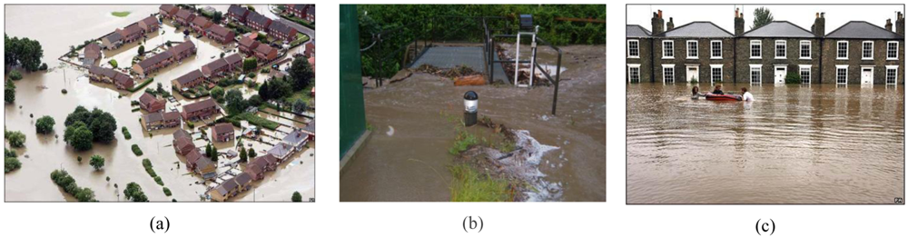
Recently, observed increases in precipitation levels in the UK are driving the need for investigation of the effects of flooding on earth walls. Evidence for this is provided by the UK Climate Impacts Program (UKCIP; www.ukcip.org.uk), which concluded that the decade of the 1990s was the wettest in the UK since records began. Some areas received one month's precipitation in just 24 hours. Furthermore, the predictions by the UKCIP09 indicate that these trends will continue with heavy precipitation becoming more frequent across the UK set to rise further. In addition, climate change is acting as a driver for large increases in flood risk worldwide and in the UK (Figure 1).
These processes of extreme precipitation create cycles of wetting/drying (wetting during rain and possible flooding, followed by drying after drainage) on the earth walls, which generate a change in the earth walls structure (fabric and bonding), strength and stiffness. When flooding occurs, the earth walls are exposed to water by submersion as well as by capillary forces, causing an increase of the degree of saturation (amount of water filling the porous of the wall) of the earth structures and therefore decreasing the suction between the particles. At low degrees of saturation (for example, before flooding), the suction is higher and this helps the bonding between particles, increases cohesion, strength and stiffness. When the degree of saturation increases (for example, during flooding), the suction decreases and the structure suffers a drastic change in strength and this can happen together with volumetric variations. After flooding, the earth structures that were exposed to water, start presenting evapotranspiration, decreasing again the degree of saturation of the earth material. Climate change is causing a rise in frequency of flooding, so repeatable flooding (wetting of the earth walls) will generate cycles of wetting/drying on the earth structures. As a consequence, all structures exposed to such weather conditions can be affected by behavioral features due to these cycles of wetting/drying and catastrophic failures can happen.
2. Preparation and Characterization of the Wall/Samples
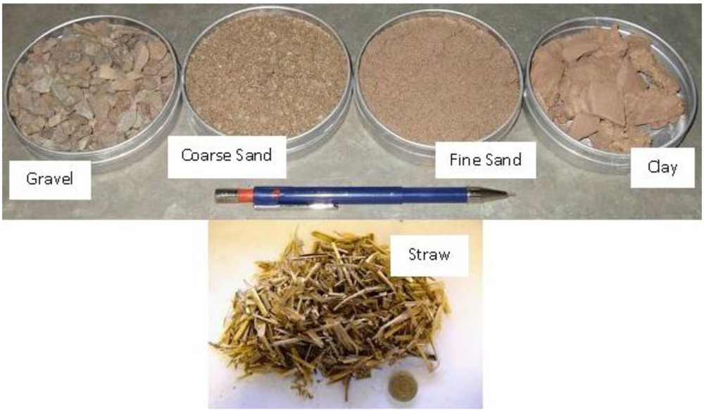
An experimental program was planned and carried out to investigate the effect of flooding events on the earth walls' response on a reduced scale in the laboratory. The first stage was to characterize the earth materials: see Table 1 and Figure 2 for the used material, particle size distribution and preparation details.
A series of tests were performed to investigate the moisture content at storage of the materials used in situ before the mixture process for building. It was observed that these materials were not completely dry and presented an average moisture content of 1.55%. For the experimental program of this study, 1.55% of water content was adopted for the mixture to reproduce the field condition when constructing.
The mixing of the materials was carefully done in the laboratory. Some characterization tests were carried out, such as liquid and plastic limit, specific gravity, compaction and unconfined compression tests. The authors took special care to reproduce—on a small scale—specimens that were representative of the process of building in situ. At the same time; attention was taken to prepare repeatable samples to allow the analysis and comparison of the obtained results.
All the wall samples were prepared without using any additives (e.g., starches, lignosulfates, or gypsum) or any coatings (e.g., clay plaster, lime plaster, gypsum plaster, limewash or paint), because it was aimed to study the most critical possible conditions without the benefits that an additive could add to the mixture and without a coating material that will improve the durability of the external face of the walls.
Table 2 presents some of the obtained results. This initial characterization was crucial to enable the second stage of the project in which wall/samples were prepared and tested under flooding conditions.
A series of compaction tests were executed during this investigation to identify the optimum water content and co-related maximum dry density for the different configurations studied (mixture without straw, mixture with 15 mm of straw, mixture with 50 mm of straw). After the mixing process of the materials described in Table 1, the mixture was placed in a steel mold and compacted with the automatic compactor following the BS 1377 [10], using the 2.5 kg rammer method. From the results of this test, it is possible to obtain the optimum moisture content (wopt), at which a maximum value of dry density is obtained. At low values of moisture content, lower than wopt, most soils tend to be stiff and are difficult to compact. As the water content (w) is increased, the soil becomes more workable, facilitating compaction and resulting in higher densities. At high water contents, higher than wopt, however, the dry density decreases with increasing proportion of the soil volume being occupied by water. Comparing the optimum water content and the maximum dry density of all three configurations of soil mixture, it was obtained:
Soil mixture without straw wopt = 7.35% and ρd = 2.09 Mg/m3
Cob with Straw cut down to 15 mm wopt = 9% and ρd = 2.045 Mg/m3
Cob with Straw cut down to 50 mm wopt = 9.3% and ρd = 2.02 Mg/m3
The obtained results show that the addition of straw affects, in terms of compaction, the amount of water that should be added to the mixture to obtain a denser soil structure. This information should be considered when mixing the earth materials for construction in the field. Another important parameter is the moisture content at storage of the materials used, which should always be verified before the amount of water that will be used for construction is decided. The authors studied the effect of straw in the building material mixture motivated by a historical building in Perthshire (Scotland), constructed between 1745 and 1770 [10], which recently started suffering due to flooding events. Part of the building had been flooded (with submergence of the base of the walls) five-times in recent years [11]. In response to these events, isolated repairs were undertaken to the damaged walls using pre-molded and dried earth blocks (clay bat), using straw as reinforcement material [8].
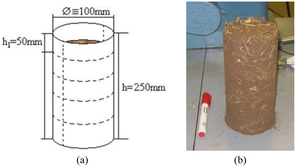
To prepare the samples, the correct amounts of each material was placed in a mixer and blended together as a dry mix until homogeneous. After, water was added in stages. The water was then mixed with the other materials until a homogeneous mixture was obtained. At this stage, the sample was ready to be molded. The molds were hollow cylinders (as shown in Figure 3(a)), that were halved so that the sample could be removed after the blows and were clamped together with Jubilee clips. These molds had marks of 50 mm on the height of the section. These were to mark where the soil layers should reach after each set of blows (see Figure 3(a)). The first layer of the mold was estimated to be filled after ramming. The mixture of the first layer was weighed and the same amount of soil was used in each layer. Each layer received the same number of blows with a manual rammer; this procedure was done by hand, as in cob construction walls and in the pre-molded blocks in Pethshire (Scotland). The authors noticed that the obtained density was dependent on the operator, as is observed in the field. A variation in the obtained density can be observed from operator to operator and should be taken into account when designing an earth structure.
The unconfined compression tests were performed to investigate the behavior of the wall/samples under simple compression; a similar situation would be observed in the field when a vertical load is applied on the top of an earth wall (see Figure 4 for the layout of the test).
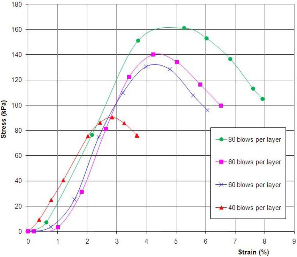
Figure 5 shows the curves obtained from carrying out unconfined compression tests for four samples prepared at different densities (40, 60 and 80 blow per layers), with an initial water content of approximately 7.8%.
It is evident that the higher the number of blows per layer, i.e., the higher the density of the wall/sample, the higher the gain in simple compression strength. When the range of the number of blows per layer between 40 and 80 was used, the capability of the wall/samples to sustain simple compression was increased: it was 78% between 40 to 80 blows, 50% between 40 and 60 blows and 19% between 60 and 80 blows.
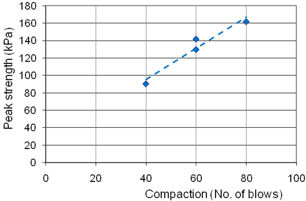
This trend in behavior is important to demonstrate the relevance of the number of blows per layer that should be used in the field. Figure 6 shows the relationship between the peak strength and the compaction rate (number of blows).
The results obtained for the maximum unconfined compression strength were smaller than those usually observed on dry rammed earth and cob due to the fact that the wall/samples were tested with a moisture content of around 7.8% as well as due to the small scale of the specimens. The authors decided to test the samples with the water content of the molding process because this is the most critical situation and the site that motivated the study (in Perthshire, Scotland), presented a high level of relative humidity.
3. Experimental Section: Flooding Simulation Test (FST)
Significant differences in the soil specific volume are observed during wetting and drying of soils [13-18]. Cycles of drying and wetting generate progressive shrinkage in clays and result in a change in fabric during drying, which weakens bonding and, as a consequence, degrades the soil structure [19]. Moreover, cycles of wetting and drying can exhibit hydraulic hysteresis [13,16], implying that two samples of the same soil subjected to the same value of suction (s, the difference between pore air pressure and pore water pressure) can be at significantly different values of degree of saturation (Sr) if one is on a drying path and the other is on a wetting path. Figure 7 presents a soil water retention curve (SWRC) of a soil illustrating hydraulic hysteresis [16]. Another important feature observed during cycles of wetting/drying is the occurrence of irreversible volume changes in the soil (e.g., collapse phenomenon) [13,14].
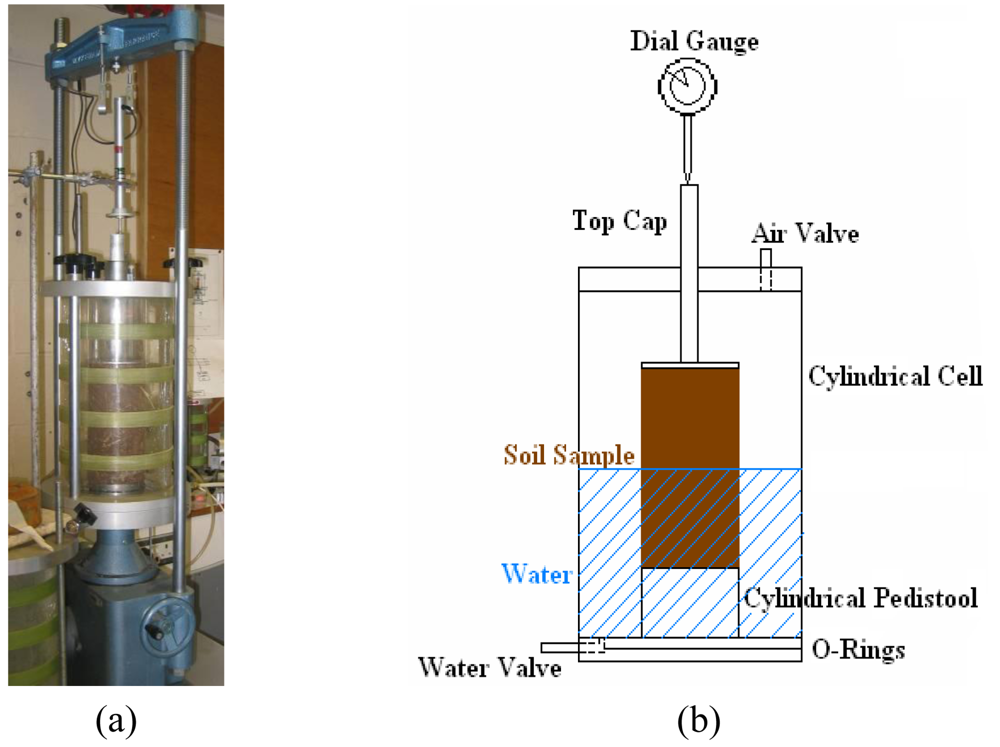
A triaxial apparatus was modified at the Soils Laboratory (Heriot-Watt University) to investigate the behavior of the wall/samples under cycles of flooding followed by drying periods, all monitored during long periods of time, around 360 hours. Figure 8 shows the layout of the apparatus. The authors called the proposed test a Flooding Simulation Test (FST). All samples were prepared in small scale (100 mm diameter × 200 mm height) in layers, as the wall/samples molded for the unconfined compression tests following the same procedure as used in the field (procedure used during the repairs in Perthshire, Scotland). The moisture content at preparation was controlled and measured, the number of blows per layer was also controlled and the density of the wall/samples was calculated using the specific gravity obtained at the first stage of the experimental program together with the dimensions and weight of the specimens.
A series of FSTs were carried out for the wall/samples prepared with 60 blows per layer with and without straw as reinforcement material. The wall/samples were exposed to flooding (see Figure 8) for a controlled time of 24, 60 and 120 hours, followed by a drained environment (without submersion in water) also for a controlled time of 72, 60 and 12 hours.
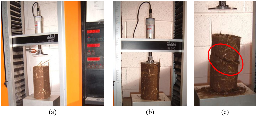
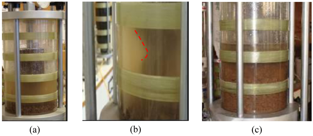
With the aim to investigate the influence of the straw as reinforcement material, one test was carried out with a wall/sample prepared without straw (un-reinforced specimen). The wall/sample was molded with 60 blows per layer, following the same procedures as previously described, and a FST was carried out (Figure 9).
The tested wall/sample prepared without straw (un-reinforced specimen) collapsed after six days under flooding conditions. There was no change in vertical displacement; however, the external walls of the sample that was under the water failed until a very small diameter of the soil was left. At this point, the weight of the top non-flooded soil was too much for such a small diameter to cope with and failure occurred. The stages of the failure can be observed in Figure 9. The process of failure forming in the flooded part of the wall/sample is evident, and the non-flooded part of the wall/sample can be seen to remain intact until a few moments before total collapse of the structure.
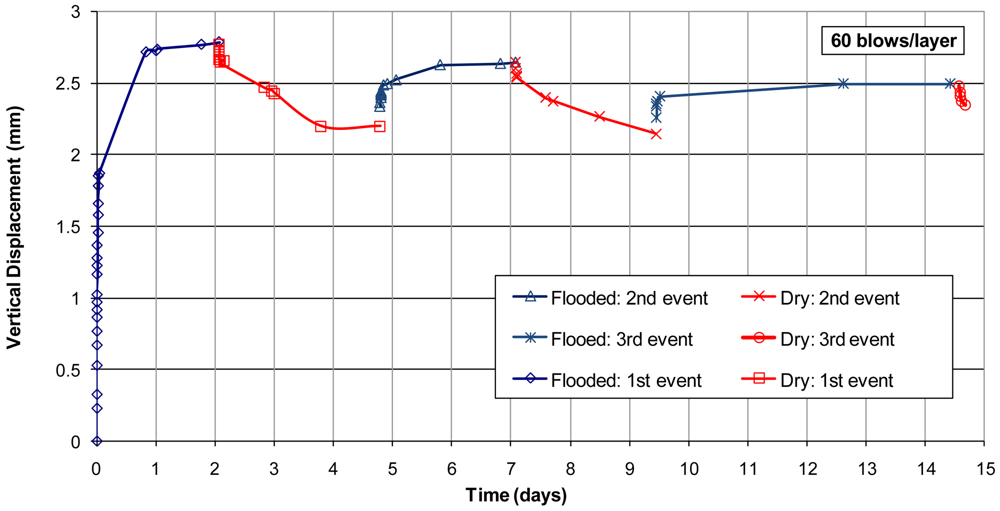
A second wall/sample was molded with 60 blows per layer with straw reinforcing. The FST was executed following cycles of wetting (wall/sample flooded to half of its height) and drying (the water around the wall/sample was drained), as shown in Figure 10. The test duration was 14 days with three cycles of wetting and drying the wall/sample.
Comparing the response after flooding of the wall/sample prepared without straw and the wall/sample prepared with straw (both with 60 blows per layer), it is evident that the straw as reinforcement of the structure has a vital role in the hydro-mechanical behavior of earth structures. It is well known that the fibers (in this case, straw) are added to earth materials mostly to reduce shrinkage and improve tensile strength [20], but this research shows that the straw reinforcement introduces another important benefit to the earth structure. In our research, the fiber (straw) modified the fabric, creating an inter-locking effect that changes the overall behavior of the earth structure when it is exposed to cycles of wetting/drying.
From Figure 10, it is also clear that with the flooding events, the wall/sample presented an increase in volume, followed by a decrease in volume when the water was drained. Keeping in mind that just half of the wall/sample was submerged in water, the first flooding event caused an increase of the vertical height equivalent to 3% of the exposed height under water. The authors believe that this behavior happened because the wall/sample was not loaded (no vertical load was applied to the top of the sample), since it is show in the literature for non-existent or low vertical stresses that the earth/soil can present expansible behavior when wetted [13,17,18,21]. If a load would be introduced to the top of the wall, the authors believe that the wall/sample could present collapsible behavior (sudden reduction of volume by rearrangement of the particles) [14,15,21]. When the water was drained, the wall/samples presented shrinkage; a volumetric reduction due to drying is a typical behavior of materials containing clay [15,16,21]. The wall/sample presented a hydraulic hysteresis [16] due to cycles of wetting/drying (repeated flooding events follow by dry events).
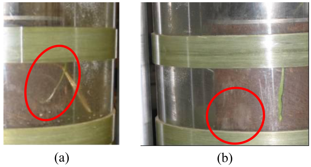
Another problem caused by wetting the earth wall/samples (reinforced by straw) was the growth of rot, as was observed during one of the FSTs after four days under flooding conditions. This shows that the introduction of water generates an environment susceptible to changes in the straw state, see Figure 11(a).
After the second flooding, the formation of fungi at the surface of the wall/sample was observed, as shown in Figure 11(b); demonstrating that microorganisms can grow inside the sample when under flooding conditions (sample wetted). The wall/sample when wetted generated an environment in which microorganisms easily reproduce.
4. Conclusions
The following conclusions can be drawn from the study:
The addition of straw to the soil mixture changes the response of the earth material to the compaction effort. However, changes in the length of the straw (15–50 mm) as reinforcement do not produce significant variations in the density of the mixture. It is interesting to highlight that the process of building the earth walls causes a cut down in size of the straw length. Furthermore, the addition of straw increases the optimum water content of the mixture.
The unconfined compression tests carried out showed a significant increase in the peak of the simple compression strength when the compaction rate was increased from 40 to 80 blows per layer, but not such an increase when the rate was increased to between 60 to 80 blows per layer.
The flooding simulation tests in wall/sample without straw (un-reinforced) presented failure of the structure after six days of flooding, different to the response observed for the wall/sample with straw. The straw works as a reinforcement of the structure.
The wall/sample reinforced with straw showed hydraulic hysteresis when subjected to cycles of wetting/drying (repeated flooding events followed by dry periods). The material demonstrated expansible behavior when wetted followed by shrinkage when dried. The authors believe that the walls could respond differently to flooding if under vertical stress (vertical load on the top of the wall). The authors would like to highlight this behavioral feature has major importance to predict the hydro-mechanical response and long-term life of such structures.
Under flooding conditions, the wall/sample reinforced with straw showed formation of fungi at the surface and some rot growth from the sample was also observed. When wetted, the earth structures produce an environment where microorganisms easily can reproduce.
This work has shown that the structural integrity of earth materials has a certain capacity to resist failure during flooding conditions when a reinforcement material such as straw is used. It must be emphasized that this is influenced by many parameters, including: mixture composition, compaction rates and the nature of the reinforcement utilized.
Future work will be undertaken to investigate the effects of flooding on earth walls under vertical load as well as studying different compaction rates, suction profiles and building procedures.


| Material | Percentage required (% by weight) | Details of preparation |
|---|---|---|
| Coarse sand | 19.7 | Dried in oven at 105 °C for 24 h |
| Gravel | 24.4 | - |
| Fine sand | 32.5 | Dried in oven at 105 °C for 24 h |
| Clay | 20.6 | Dried in oven at 105 °C for 24 h |
| Straw | 1.25 | Cut into approximate length of 15–50 mm* |
| Water | 1.55 | - |
*Depending on the aim of the test.
| Plastic Limit | 14.6% |
| Liquid Limit | 22.5% |
| Plasticity Index | 7.9% |
| Specific Gravity (without straw) | 2.6 |
| Specific Gravity (with straw) | 2.5 |
Acknowledgments
The authors thank Alastair MacFarlane for general assistance during the experimental program.
References and Notes
- Berge, B. The Ecology of Building Materials, 2nd ed.; Architectural Press: Oxford UK, 2009. [Google Scholar]
- Perroni, C. Prefabricated earth constructions in the UK and Europe. Struct. Eng. 2008, 86, 32–39. [Google Scholar]
- Little, B.; Morton, T. Building with Earth in Scotland: Innovative Design and Sustainability; Scottish Executive Central Research Unit: Edinburgh, UK, 2001. [Google Scholar]
- Weismann, A.; Bryce, K. Building with Cob: A Step by Step Guide; Green Books: Dartington, UK, 2006. [Google Scholar]
- Jaquin, P.A.; Augarde, C.E.; Gerrard, C.M. Analysis of Historic Rammed Earth Construction; Louranco, P.B., Roca, P., Modena, C., Agrawal, S., Eds.; Structural Analysis of Historical Constructions: New Delhi, India, 2006. [Google Scholar]
- Medero, G.M.; Forster, A.; Morton, T.; Kennedy, J.; Buckman, J. Cob construction in Scotland: Case study old school house at Cottown, Perthshire. Proceeding of the 1st Mediterranean Conference on Eart Architecture, Cagliari, Italy, 13–16 March 2009; UNESCO World Heritage Centre: Cagliari, Italy, 2009. [Google Scholar]
- Hall, M.; Djerbib, Y. Moisture ingress in rammed earth: Part 1—The effect of soil particle-size distribution on the rate of capillary suction. Construct. Build. Mater. 2004, 18, 269–280. [Google Scholar]
- Forster, A.; Medero, G.M.; Morton, T.; Buckman, J. Traditional cob wall: Response to flooding. Struct. Survey 2008, 26, 302–321. [Google Scholar]
- Williams-Ellis, C.; Eastwick-Field, C.; Eastwick-Field, E. Building in Cob, Pise, and Stabilised Earth, reprinted ed.; Donhead Publishing: Shaftesbury, UK, 1999. [Google Scholar]
- Reen, K. Conservation of Earth Buildings in Scotland: The Old Schoolhouse, Cottown, Perthshire; Kirsty Reen Reports on a Generally Successful Project, Institute of Historic Building Conservation: Tisbury, UK, 1999. Available online: www.ihbc.org.uk/context_archive/63/schoolhouse/cottown.html (accessed on 2 December 2010).
- Morton, T.; Little, R. Mixing It with Lime and Clay; Building Limes Forum: Edinburgh, UK, 2008; Volume 14. [Google Scholar]
- BS 1377-4: Methods of Test for Soils for Civil Engineering Purposes—Part 4: Compaction-Related Tests; British Standards Institution: London, UK, 1990.
- Medero, G.M.; Schnaid, F.; Gehling, W.Y.Y. Oedometer behaviour of an artificially cemented highly collapsible soil. J. Geotech. Geoenviron. Eng. 2009, 135, 840–843. [Google Scholar]
- Medero, G.M.; Schnaid, F.; Gehling, W.Y.Y.; Gallipoli, D. Analysis of the mechanical response of an artificial collapsible soil. Proceedings of the International Symposium on Experimental Evidence Towards Numerical Modelling of Unsaturated Soils, Weimar, Germany, 18–19 September 2003; Springer: Berlin, Germany, 2004; pp. 135–146. [Google Scholar]
- Sivakumar, V.; Tan, W.C.; Murria, E.J.; McKinley, J.D. Wetting, drying and compression characteristics of compacted clay. Geotechnique 2006, 56, 57–62. [Google Scholar]
- Wheeler, S.J.; Sharma, R.S.; Buisson, M.S.R. Coupling of hydraulic hysteresis and stress-strain behaviour in unsaturated soils. Geotechnique 2003, 53, 41–54. [Google Scholar]
- Sharma, R.S. Mechanical Behaviour of Unsaturated Highly Expansive Clays. Dphil Thesis, University of Oxford, Oxford, UK, 1998. [Google Scholar]
- Alonso, E.E.; Lloret, A.; Gens, A.; Yang, D.Q. Experimental behaviour of highly expansible double-structure clay. Proceedings of the 1st International Conference on Unsaturated Soil, Paris, France, 6–8 September 1995; Balkema: Rotterdam, The Netherlands, 1995; pp. 11–16. [Google Scholar]
- Cafaro, F.; Cotecchia, F. Structure degradation and changes in the mechanical behaviour of a stiff clay due to weathering. Geotechnique 2001, 51, 441–453. [Google Scholar]
- Morton, T. Earth Masonry, 1st ed.; BRE Press: Watford, UK, 2008; pp. 43–125. [Google Scholar]
- Haghighi, A.; Medero, G.M.; Woodward, P.K.; Laloui, L. Effect of temperature on collapse potential of kaolin clay. Proceedings of the International Conference on Unsaturated Soils, Barcelona, Spain, 6–8 September 2010; Taylor & Francis Group: London, UK, 2010; pp. 543–548. [Google Scholar]
© 2010 by the authors; licensee MDPI, Basel, Switzerland. This article is an open access article distributed under the terms and conditions of the Creative Commons Attribution license (http://creativecommons.org/licenses/by/3.0/).
Share and Cite
Medero, G.M.; Kennedy, J.H.; Woodward, P.K.; Banimahd, M. Flooding Effect on Earth Walls. Sustainability 2011, 3, 69-81. https://doi.org/10.3390/su3010069
Medero GM, Kennedy JH, Woodward PK, Banimahd M. Flooding Effect on Earth Walls. Sustainability. 2011; 3(1):69-81. https://doi.org/10.3390/su3010069
Chicago/Turabian StyleMedero, Gabriela M., Justin H. Kennedy, Peter K. Woodward, and Meysam Banimahd. 2011. "Flooding Effect on Earth Walls" Sustainability 3, no. 1: 69-81. https://doi.org/10.3390/su3010069