Article

A Cradle to Handover Life Cycle Assessment of External Walls: Choice of Materials and Prognosis of Elements

by
Diana Carolina Gámez-García
1,
José Manuel Gómez-Soberón
2,*,
Ramón Corral-Higuera
3,
Héctor Saldaña-Márquez
1,
María Consolación Gómez-Soberón
4 and
Susana Paola Arredondo-Rea
3
1
Barcelona School of Architecture, Polytechnic University of Catalonia, 649 Diagonal Avenue, 08028 Barcelona, Spain
2
Barcelona School of Building Construction, Polytechnic University of Catalonia, 44-50 Doctor Marañón Avenue, 08028 Barcelona, Spain
3
Mochis Faculty of Engineering, Autonomous University of Sinaloa, no number Fuente de Poseidón y Ángel Flores, 81210 Los Mochis, Mexico
4
Civil Engineering School, Metropolitan Autonomous University. Av. San Pablo 180, 02200 Mexico City, Mexico
*
Author to whom correspondence should be addressed.
Sustainability 2018, 10(8), 2748; https://doi.org/10.3390/su10082748
Submission received: 6 July 2018 / Revised: 28 July 2018 / Accepted: 28 July 2018 / Published: 3 August 2018

Abstract

:
This research focuses on a comparison of 20 external wall systems that are conventionally used in Spanish residential buildings, from a perspective based on the product and construction process stages of the life cycle assessment. The primary objective is to provide data that allow knowing the environmental behavior of walls built with materials and practices conventionally. This type of analysis will enable promoting the creation of regulations that encourage the use of combinations of materials that generate the most environmentally suitable result, and in turn, contribute to the strengthening of the embodied stages study of buildings and their elements. The results indicate that the greatest impact arises in the product stage (90.9%), followed by the transport stage (8.9%) and the construction process stage (<1%). Strategies (such as the use of large-format pieces and the controlled increase in thickness of the thermal insulation) can contribute to reducing the environmental impact; on the contrary, practices such as the use of small-format pieces and laminated plasterboard can increase the environmental burden. The prediction of the environmental behavior (simulation equation) allows these possible impacts to be studied in a fast and simplified way.

1. Introduction

The construction industry is responsible for the unsustainable use of natural resources, and is an important source of air, soil, and water pollution [1]. Published data indicate that this sector uses between 30–40% of primary energy worldwide [2], with these figures including the energy required by the buildings [3,4,5]. The costs of the primary energy consumed by buildings for some countries are 23% in Spain, 39% in the United Kingdom, 47% in Switzerland, 50% in Botswana, 40% in Europe, 25% in Japan, 28% in China, and 42% in Brazil [6]. Most of this energy consumption is due to heating, ventilation, and air conditioning throughout the building’s operating life [7,8,9]. Studies have shown that most of the environmental impacts occur in this phase, representing approximately 80-90% of the total impacts generated in the useful life of the building [8,10,11,12,13,14,15,16,17].
Currently, the energy demand of a building is closely linked to the efficiency of its envelope [6] as well as its thermal properties. The envelope includes the walls, ceilings, doors, windows, and any peripheral element of the building [18]. The thermal properties of the materials used will determine their ability to absorb or emit longwave solar radiation, particularly the U-value (thermal transmittance) [9].
Although there are relevant conclusions about the envelope’s influence on the energy efficiency of a building, there is still no consensus about the implication of its construction and previous phases (A1–A3 product stage; A4–A5 construction process stage, UNE-EN 15804:2012 +A1 [19]) in the overall environmental impacts of the building. This may be because stages A1–A5 generate a lower environmental impact (between 8–20%) in the life cycle of the building [8,10,11,12,13,14,15,16,17]. It has been established in previous studies that the operation phase must be included in the life cycle assessment (LCA) as a priority [20], but without omitting the rest of the phases, since the impact cannot be considered negligible [7,21]. Some researchers [20,22,23] consider that investing resources in the embodied stages would lead to buildings becoming more efficient in the operational stage.
The external walls (EW) are essential parts of the building envelope, since they provide thermal and acoustic comfort; their design allows passive control of the interior conditions of the building through management of the external temperature transfer [9]. Previous studies have found that EWs are important contributors of embodied energy, due to the use of the large amounts of material that are required [24]. Some of the tested practices in the search for improved behavior include green walls for facades [25], the use of insulation for external walls [26,27,28], and the use of appropriately sized windows (glass with the correct thermal coefficients).
The correct choice of materials is capable of generating substantial environmental deflation throughout the complete life cycle of the building [29,30,31]. However, the use of these alternative technologies has been limited due to the incorrect assumption that buildings with high energy efficiency are also more costly to construct, and thus, from an economic perspective, are of less interest to developers [32,33].
The effects on the external wall due to environmental actions and the resulting impacts depend on several factors. These include the wall configuration, the combination of materials within the wall, the airtightness of the wall system, and the specifics of each building and location. This makes the LCA of walls and related research a necessity. The LCA is a recently adopted method in the construction industry; it is one of the dimensions of the life cycle sustainability assessment (LCSA) [34,35,36].
The LCA has allowed detailed studies of all stages in the life of a building (with reliable and comparable results). Despite being a relatively young methodology in this field, the LCA may provide a solution to the environmental challenges currently affecting the sector. These include the significant consumption of energy and raw materials, solid waste management, and greenhouse gas emissions (GHGs) [3,14,37,38,39,40,41,42], making this an essential instrument with a view to the future.
The studies in which the built-in stages of constructive elements are addressed in detail are limited because the greatest environmental implication arises in the operation of a building. On the other hand, there is also an important number of studies that analyze conventional and alternative construction materials. However, it is necessary to analyze how these materials behave when they are integrated in a constructive element of a building from a perspective specific to the design of the element (stages A1–A5), and not as a consequence of its use. In this sense, this research focuses on the study of that fundamental part of the envelope: the walls. The study was carried out from a construction-focused perspective, and thus analyzes stages A1–A5 of the LCA of a building [19]. The main objective is to provide data that facilitate the future promulgation of regulations that allow the election of adequate and sustainable wall systems.

2. Materials and Methods

2.1. Aim and Scope of the Study

The aim of the analysis was to compare the environmental performance of 20 external wall systems (of three layers) used in Spanish residential buildings through LCA, varying the materials used for each layer (type of wall and thermal insulation), and define the results of the environmental impact through a system of equations.

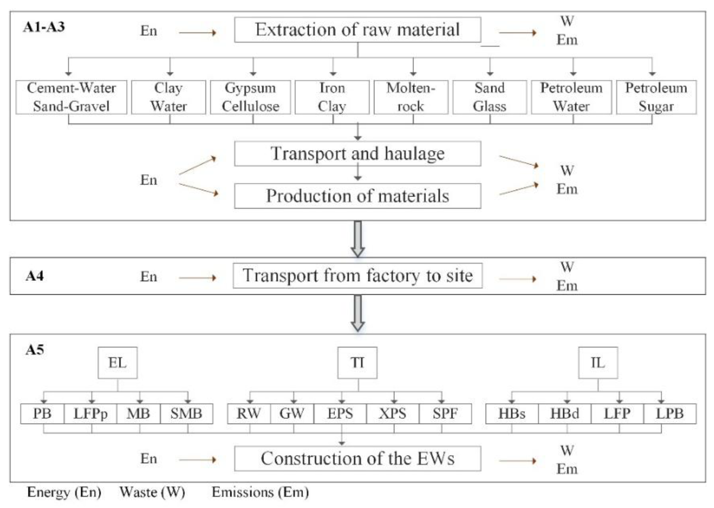
2.1.1. System, Boundaries, and Functional Unit

Each analyzed system has the function of an external wall that is part of an envelope of a residential building. The analysis proposed for this study is known as “cradle to handover” [43], which includes the stages: raw materials supply (A1), transport (A2), and manufacturing (A3) (product stage or cradle to gate); and transport from factory to site (A4) and construction process (A5) [19]. Figure 1 shows the flow chart of the life cycle inventory (LCI) process used in the studied external walls. The stages of use (B1–B7) and end of life (C1–C4) have not been considered in this research, as it is intended to define which walls are the most optimal (environmentally and thermally) from the perspective of their production and construction, rather than as a consequence of their use.
In this sense, it has been taken for granted that the envelope of a building (especially the external walls) is decisive for having an important environmental impact in the operation stage; however, this hypothesis underestimates the impact of the envelope itself. In addition, considering the time in which each stage of the life cycle occurs, stages A1–A5 are developed in considerably shorter periods than stages B1–B7 (specifically B6 and B7). Therefore, the environmental implications of stages A1–A5 will be greater in terms of environmental impact/building lifespan.
Recent studies have carried out analyses of different types of constructions, such as buildings [44,45,46,47,48] or pavements [49,50,51,52], exclusively considering stages A1–A5 or similar (A1–A4 and A1–A3). The objective of these works is to help researchers conduct environmental assessments in a fast, effective and sustainable way [44], and provide tools that contribute to a better practice of the stages involved in the construction.
In this sense, researchers have studied the carbon footprint of conventional buildings [44] and the built-in energy of industrialized construction buildings that solve the growing demand for housing [46]. Meanwhile, to address the lack of energy data in construction, hybrid LCI models have been developed [47]. On the other hand, to promote the use of alternative materials, the environmental impacts caused by the use of wood and conventional materials in buildings have been compared [45,48].
For the purposes of the comparative study, a square meter of external wall was chosen as a functional unit; being a physical element, it is intuitive, easily understood, and easily compared. In previous studies [8,53,54], this criterion has ensured that the functional unit would lead to reliable results.

2.1.2. Data Inventory

Ecoinvent 3.2 was chosen as a database to obtain the LCI for the materials and processes used in this study. Ecoinvent is recognized internationally as being exhaustive and transparent, with up-to-date and consistent data for energy and material supply as well as for resource extraction, the use of chemical products, metallurgy, agriculture, waste management, and transport [55]. It has been widely utilized in previous building LCA studies [56,57,58]. Since Spanish-specific LCI data were not available [59], its application to the scope of research may be considered credible and reliable when considering information mostly referring to the European area.
To quantify the materials used in each component of the external walls, this study uses information from the data contained in the Structured Bank of Constructive Elements Data (BEDEC) of the Institute of Construction Technology of Catalonia (ITeC) [60]. BEDEC is a materials database with information on construction products, which incorporates constructive elements of typologies such as building, and contains technical characteristics referring to the Spanish area.

2.1.3. Impact Assessment Method and Categories

The CML 2001 (Leiden University’s Center for Environmental Science) [61] was chosen as an environmental impact method, since it is considered for application in the Spanish sector and includes normalization factors of both European and global scope. Additionally, its indicators are given in kg of substance equivalent, which makes them expressible in technical and objective terms, and eases their comparison with other research. The CML includes impact categories of collective interest such as:
  • Climate change (CC) [62]
  • Depletion of abiotic resources (ADP) [63]
  • Acidification potential (AP) [62]
  • Eutrophication potential (EP) [64]
  • Human toxicity (HTP) [65]
  • Photochemical oxidation (POCP) [62]
  • Stratospheric ozone depletion (ODP) [62,64].
The Software LCA Manager 1.3 [66] was used to support the management of information on the environmental impacts, which allowed the resources used and their environmental effects to be analyzed, ordered, grouped, and classified according to the LCA methodology [67]. This software has been used in previous studies, with satisfactory results [12].

2.1.4. Assumptions

For the evaluation of A4–A5, the following assumptions were made. For A4, the site of Plaza Cataluña was considered as the benchmark due to its central and strategic location. For A5, the number of floors aboveground (weighted average) of buildings destined for housing in Barcelona was established using the data obtained from its Department of Statistics [68]. A crane was considered for the construction process, which allows access to the material for the conformation of the walls. Therefore, buildings of one and two floors were discarded. Consequently, according to these criteria, the average building in Barcelona destined for housing is of six floors. In addition, it was considered that each of these levels has a between-floor height of three meters (2.5 m free between levels, with upper and lower slabs of ≈25 cm each) [69]. Therefore, the average height of reference (HR) used in A5 in this study is 18 m (including the complete up–down cycle).

3. Case Studies

For the present study, 20 external wall systems conventionally used in Spanish residential buildings were selected. Although the data provided for the proposed alternatives (materials and types of walls) correspond to the Spanish stock, these can be considered conventional, even in other European countries [25,38]. The external walls are composed of an exterior layer (EL), which is generally exposed to the thermal conditions produced by the climate; then, there is a thermal insulation (TI), which helps provide adequate hygrothermal comfort as well as energy efficiency; finally, there is an interior layer (IL) in contact with the habitable space of the system, which is subject to its own internal conditions.
The optimum comparative configuration of the external walls that were studied was carried out by means of an iterative process, which involved evaluating the different geometric thicknesses and the material types that make up each of the layers. With each proposed solution, the physical and mechanical properties of each external wall were then evaluated. Finally, those that showed equivalence in terms of a similar total thickness (EL + TI + IL), compression strength, and thermal and fire resistance (i.e. equivalent functionality), were chosen. The configuration and properties of the walls are shown in Figure 2.
With regard to the thermal requirements of the walls, they were dealt with in accordance with the basic document DB-HE-1 of the Spanish building technical code (CTE) [70] for the climatic zone classified as C2, corresponding to the city of Barcelona (Table B.1 of the DB-HE-1, climate zones of the Iberian Peninsula). The U-value in all of the external wall combinations studied was always below the established limits for facade walls and enclosures in contact with the terrain (0.73 W/m2K).
Additionally, as a guarantee of equivalence among all of the systems studied, equivalent construction solutions were provided that showed a lower variation of U-value (0.098 W/m2K) in all of the comparisons. The minimum U-value was 0.61 W/m2K, and the maximum U-value was 0.70 W/m2K. The average of the 20 systems was 0.65 W/m2K. The thicknesses of each solution in their total transversal section were adjusted until a maximum variation of 16% was attained, with extreme dimensions of between 23.5–28 cm, these sections were considered conventional for external walls in multi-storey Spanish residential buildings. The U-value and thickness for each external wall are shown in Table 1.
The options chosen for making up the exterior layers were elements of ceramic clay pieces (CCP) and mortar pieces (MP) of grey cement. Ceramic clay pieces and laminated plasterboard (LPB) were used for the interior layers. Materials derived from natural wool and petroleum, with similar physical and mechanical performance, were chosen as thermal insulation. The specific physical characteristics of the elements chosen for configuring the walls are shown in Table 2. The finishes to cover the walls on their exterior and interior faces were of cement mortar (mor) and laminated plasterboard (G). The normalized compressive strength for the exterior and interior layers was 10 N/mm2 and 3–5 N/mm2 respectively, and was considered null for thermal insulation.
The materials used have a limited or insignificant contribution to the spread of fire according to their classification in UNE-EN 13501-1. As these materials are of petrous origin, they are considered inert and incombustible, and are classified as A1 according to the Euroclasses for building elements [80]. The polymers (XPS, EPS, and SPF) are an exception, being combustible due to their organic nature, and have been classified as “category E” in the most unfavorable cases (direct exposure). However, for the final application of this work, they have been classified as B-S1, d0 because of the finish used (plaster and mortar) [81,82,83].

4. Life Cycle Inventory

4.1. Product Stage (A1–A3)

The inventory of the study was carried out after the samples had been defined, their equivalence of functionality corroborated (taking into account their most important physical characteristics), and the objectives and scope of the LCA established.
For the evaluation of the product stage (A1–A3), the quantities (by weight) of material required (WMFU) to configure each element of the external wall were determined per the selected functional unit, the square meter. In each element studied, waste coefficients were applied. Only those components that exceeded 1% by the weight of each wall were considered. As the materials studied are either inert or the insulation of natural wools or petroleum derivatives, the percentage excluded does not represent a potential risk (substances neither dangerous nor highly contaminating). Table 3 shows the quantities for the boundaries established (A1–A3, A4, and A5) and the datasets selected from Ecoinvent.

4.2. Transport from Factory to Site (A4)

The evaluation of A4 considers the WMFU (in tons) and the average distances from factory to site (in km). The distances were established by using the factory location of each material as the starting point and a central location in the city of Barcelona as an end point, for which a map application with geo-referencing and a route optimizer (Google maps) was used. For each type of material, the average of three factories, located in a radius of approximately 100 km, is considered. The average distances (AD) used were as follows: 70 km for CCP; 60 km for MP, 25 km for mor; 125 km for LPB; 100 for RW, GW, and XPS; 50 km for EPS; and 60 km for SPF.
A lorry with the following characteristics was considered for transporting the external walls components: load capacity (LCL) of 16 tons, cabin dimensions of 2.1 m wide by 2.2 m high, and a distance between axles of 3.5 m. These specifications satisfied the requirements of weight and maximum size for short-haul transport within a city [84]. Equation (1) was used for the environmental evaluation related to the movement impacts of the lorry (MIL in ton-kilogram, tkm):
MI L = AD   ×   WM FU

4.3. Construction Process (A5)

Stage A5 contemplates the use of machines to transport the material to each floor of the building and the elaboration of the binders used in the manufacturing of the walls. First, Equation (2) was used to estimate the time of use required (TUC [h]) for a two-ton crane (load capacity (LCC) with an average velocity (VAC) of 16.5 m/min, a potency (PC) of 7.5 kW, and a useful life (ULC) of 10,000 h [55]) to complete a full cycle to the center of the building (HR is 18 m). Similarly, two more parameters were determined by means of Equations (3) and (4) for evaluating the crane’s impact: the portion of use (crane: PUC [h/h]) and the operating energy required (EOC [kWh]):
TU C =   ( WM FU LC C ) × H R V C
PU C =   TU C UL C
EO C =   TU C   ×   P C
Finally, with regard to the manufacture of the mortar mixes used in joining the ceramic pieces and the finishes, as well as for the plaster mixes used in the adhesion of the laminated plasterboard of each wall separately, the operating energy (EOM [kWh]) of a continuous mixer was considered (average flow capacity (FC) of 13 l/min and a nominal potency (PM) of 2.2 kW). The volumes of binder (VB = sum of plaster and mortar in each wall) were quantified and, considering the FC, the time of use required (TUM) was obtained. The EOM required for the job was obtained by using the PM. By means of Equations (5) and (6):
TU M =   V B FC
EO M =   TU M   ×   P M

5. Results of the Environmental Impact

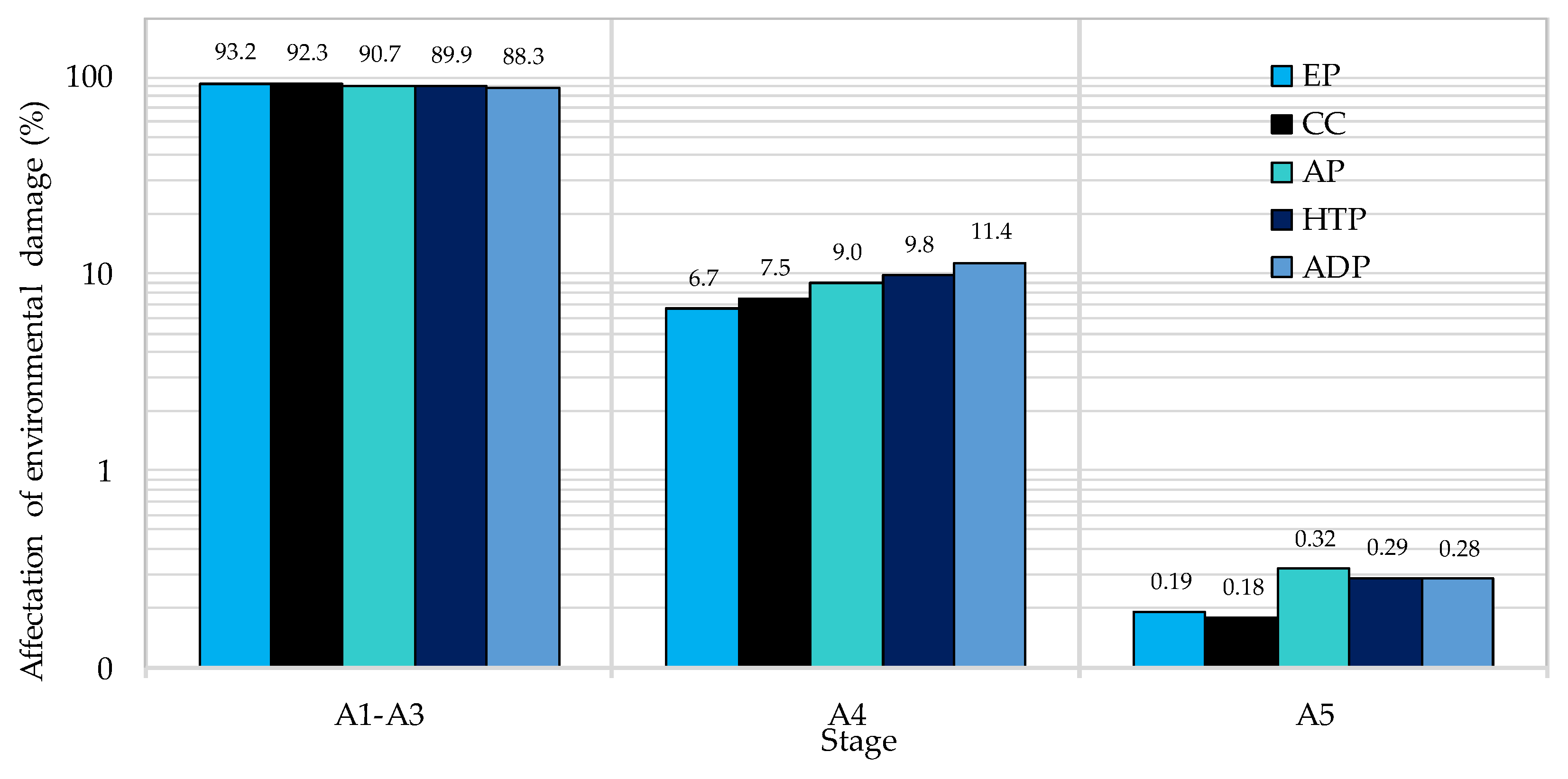
5.1. Stages of Product (A1–A3) and of the Construction Process (A4–A5) in the Impact Categories

The environmental impact assessment establishes a link between the elementary inputs to the system of the products and processes analyzed, and their potential environmental impacts [85]. Figure 3 shows the percentage of environmental damage generated by the average of the 20 external walls (including all of their elements) in each stage analyzed. For all of the categories, the greatest environmental impact arises in the product stage (A1–A3), with an average of 90.9%, confirmed by previous research [12,47]. The subsequent stage is the transport from the factory to the construction site (A4), with 8.9% of the average impact. Lastly, the construction process stage (A5) generates less than 1% of the environmental load. The values obtained for transport and construction, despite depending on the inventory data of this study and the regional characteristics established, are consistent with the results of other investigations [30,38,49].
The impact categories with the greatest repercussion in the product stage (A1–A3) are EP (93.2%) and CC (92.3%). This is because most of the GHGs (mainly CO2 and N2O) are part of the chemical reactions that occur during the manufacturing of conventional products that are used in the construction of walls, such as mortar and clay pieces. The high temperatures used in the firing of the ceramic pieces, over 1300 °C [86], and the cement clinker, over 1400 °C, as well as the high content of carbonates found in their most important raw materials (limestone and clay) are responsible for the release of CO2 into the atmosphere [87]. Similarly, the production of nitrogenous gases is inevitable due to the high temperatures reached in cooking the pieces [88]. In the stages of the construction process, the ADP presents the highest values for A4, with 11.4%, and the AP for A5, with 0.32%. This is because the transport sector is closely linked with the use of fossil fuels (sources of potentially acidifying substances, such as NOX and SO2 emissions) [89].
With regard to the POCP and the ODP, the 20 walls only reached values of the order of 10E-3 (kg ethylene eq.) and 10E-6 (kg CFC-11 eq.), respectively, at their most polluting stage (A1–A3). The first of the categories is due to the problem of air quality, which is caused by a combination of high-density car traffic in urban areas, strong incidences of solar radiation, and the high frequency of meteorological situations that inhibit air circulation (factors that impact on the formation of ozone and toxic gases in the troposphere) [62]. On the other hand, with respect to ODP, the agreements established in the Montreal Protocol limit the substances in this category to critical or essential uses [64]. The contribution to both impact categories generated by the use of external walls was considered as null, because the activities that produce them are not present in the analyzed stages.

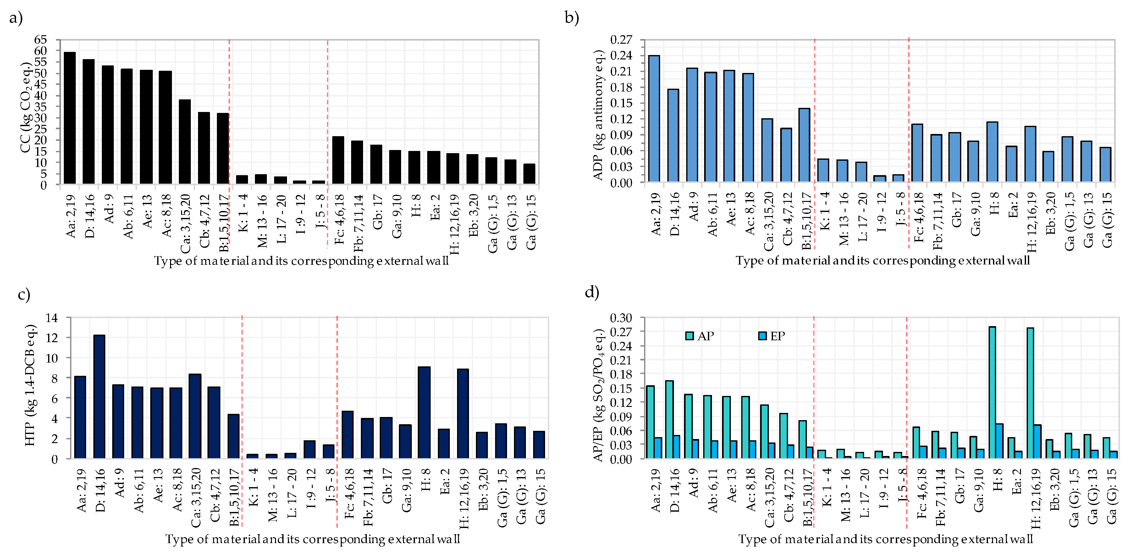
5.2. The External Walls in the Environmental Impact Categories

The external walls with the best overall environmental performance were walls 1, 3, 5, 7, 10, 15, 17, and 20, which presented the most favorable values in a minimum of four impact categories (and of these, the walls 1, 3, 5, 10, 15, and 20 in the five categories). Figure 4 shows the results of the five impact categories for the 20 external wall systems, including the three elements that compose them and the stages analyzed. As a selection criterion, the wall with the best environmental performance was taken as a reference. Consequently, only those that were 10% above this value were selected, assuming that these walls could be considered equivalent to the reference wall for each category. Walls 7 and 17 did not meet this criterion in some of the five impact categories (seven in HTP, 17 in ADP), but they are still considered acceptable, as their values continue to be close to this one.
The walls with the best overall environmental performance (1, 3, 5, 7, 10, 15, 17, and 20) have the use of large-format lightweight pieces in their conformation (such as LFPp or MB) in common, and in some cases, the option of tongue and groove. The manufacture of lighter walls (mortar and clay) will require less raw material, and therefore lead to a reduction in substance generation. In addition to the optimization of the binders destined for their conformation, reductions could be made in the impacts produced in the construction process (lighter walls generate up to 60% less pollution for CC, AP, and EP, 70% for ADP, and 30% for HTP).
For the selection of the walls with the worst environmental performance, the wall with the most unfavorable value was considered as the reference for each impact category, along with all those lower than it by 10% (see Figure 4). The options 2, 16, 18, and 19 are the ones with the worst environmental profile in the CC and in the ADP; they have the use of compact and small-format pieces for the conformation of the walls in common. With respect to the AP, EP, and HTP, walls 8, 16, and 19 presented the most adverse values; in addition to having dense and small-format pieces in the exterior layer, they use LPB as the interior layer. Therefore, the impact is attributed to both the heavy walls and the use of the galvanized profile of the LPB. The most unfavorable combination for all of the categories are walls 16 and 19, with an exterior small-format layer and an interior layer of LPB.
Considering not only the environmental profile, but also their U-value, the walls that could be recommended as suitable systems are numbers 7 and 10 (U = 0.61 W/m2K [Umin]), wall 3 (U = 0.63 W/m2K), wall 17 (U = 0.64 W/m2K), and walls 1 and 5 (U = 0.65 W/m2K), all of which were below the average U (0.65 W/m2K). The walls with the worst thermal and environmental performance are 19 (U = 0.68 W/m2K) and 8 (U = 0.7 W/m2K). This suggests that the selection of elements with better physical capacities can in turn generate a lower environmental burden; therefore, this selection of elements and materials will be a determining factor in environmental optimization. In addition, the use of external walls with better thermal capacities could lead to savings in the operation stage of the building (B6); consequently, the environmental load will continue to be smaller.
When analyzing the five impact categories, two main groups emerged in terms of the trends shown in the results obtained. On the one hand, CC and the ADP are proportionally related, since the causes of GHGs mostly originate in the use of abiotic resources. In the case of AP, EP, and HTP, the first two, despite being different phenomena, are generated by the same substances (even the Eco-indicator 99 includes them in the same impact category).

5.3. The Constructive Elements (EL, TI, and IL) in the Product Stages (A1–A3)

The impacts of the different construction components (EL, TI, and IL) that make up each external wall of the study in stages A1–A3 (due to the significance of their maximum environmental impact) are presented in Figure 5. In this study, for the CC and the ADP, the amount of material (in weight) defines the general behavior of the external walls (and secondly the type of material). Therefore, the exterior layer generates the most environmental impact on these categories, followed by the interior layer and the thermal insulation. In the case of impact categories HTP, AP, and EP, behavior is influenced more by the type of material than the quantity. On the horizontal axis of Figure 5, the type of material that composes each element of the wall (see the nomenclature in Figure 2) can be seen, followed by the external wall containing it (for example, Aa: perforated brick of 290 mm x 50 mm, incorporated in walls 12 and 19). Figure 5d includes the AP and the EP, because the results for these categories show the same trend (with different values).
The results for the exterior layers are shown in the first segment of Figure 5a (CC) and Figure 5b (ADP). The walls made with ceramic clay pieces generate 1.14 times more CC and 1.5 times more ADP than those made with mortar pieces. This is despite cement, which is known for its high pollutant rates [90], being a fundamental component in the manufacture of mortar. However, the mortar pieces only contain about 15% cement [55], and since the rest of its components are aggregates and water, the ceramic options are more harmful for these impact categories. Previous research has found that clay piece walls are more significant in terms of environmental impact than mortar piece walls [91]. In addition, the exterior layers made with small-format pieces (PB: 12, 19, 9, 6, 11, 13, 8, 18; SMB: 14, 16) are up to 60%, and 70% more polluting than those of large-format (LFPp: 1, 5, 10, 17; MB: 3, 15, 20, 4, 7, 12) for CC and ADP, respectively.
In the second segment of Figure 5a,b, it can be seen that thermal insulations made from hydrocarbons (XPS, EPS, and SPF) are on average 2.3 (CC) and three (ADP) times more harmful than natural wool (GW, RW). Therefore, from this perspective, it would be preferable when building external walls to use a thermal insulation such as GW and RW.
The third segment of the same figures shows that the interior layers made with ceramic clay pieces generate 1.14 times more CC than those made with LPB, although they represent only 15% by weight of the ceramic pieces. The interior layers of LPB (8, 12, 16, and 19) generate 1.27 times more ADP than the rest of the interior layers. In addition, the influence of G as finished (ILs 1, 5, 13, and 15) can be observed.
In the first segment of Figure 5c,d, the results of the exterior layers are shown regarding HTP and AP–EP. The exterior layers that use mortar pieces generate 1.4 times more HTP than those using ceramic clay pieces. This may be due to the heavy metals and volatile elements present in cement production [88], or the use of alternative fuels that incorporate hazardous waste [92] (such as potential generators of polychlorinated dibenzo-p-dioxins (PCDD) and dibenzofuranes (PCDF) [93]). Previous research has found similar results for HTP and AP [94]. The exterior layers made with ceramic clay and mortar pieces have a similar behavior for AP and EP. This can be attributed to the sulfurous processes that take place in the production of both types of industries for ceramic and mortar pieces (due to the fuels used and the raw material) [86]. For the three previous categories, the options made up of small-format pieces are up to 51% more polluting than those of large-format pieces (MB and LFPp).
In the case of thermal insulations (the second segment of Figure 5c,d), the natural wools generate 3.4 times more HTP than those derived from petroleum. For the case of the AP, petroleum-based thermal insulations are 1.15 times more polluting than those derived from natural wool. The contribution that thermal insulations have in the EP was considered null for the quantities that are needed in the configuration of these external walls.
The results for the interior layers are shown in the third segment; those made with LPB presented 2.5, 5.3, and 3.7 times more HTP, AP, and EP, respectively, than those made with ceramic clay pieces. These values are 80% (minimum value for the three impact categories) due to the galvanized film that covers the steel profile (also found in previous studies [12]); so, the laminated plasterboard (G) itself does not represent a substantial problem in the generation of these categories. The interior layers of large-format pieces (LFP) are on average 21% less polluting than those of hollow bricks (HB) for the three impact categories.

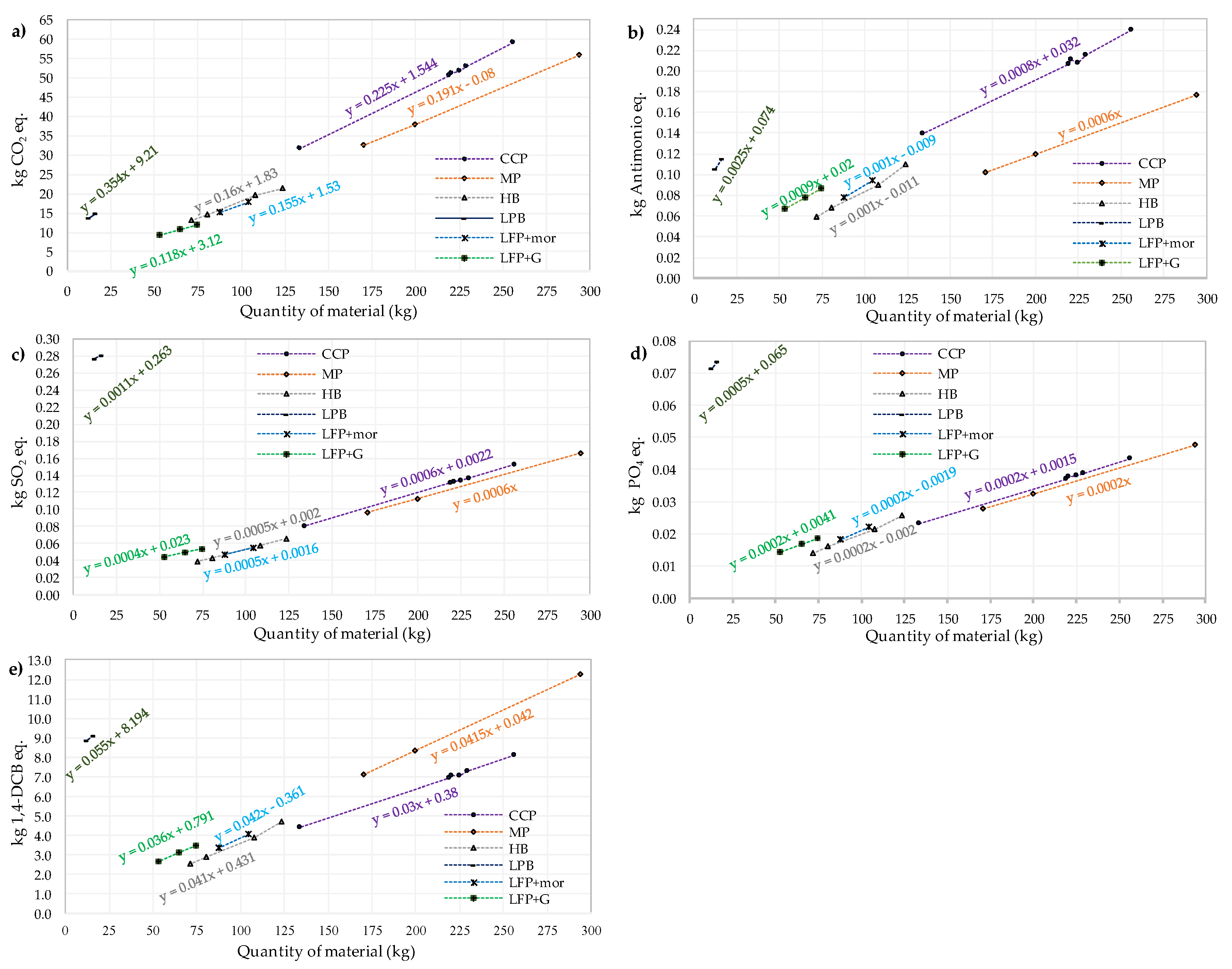
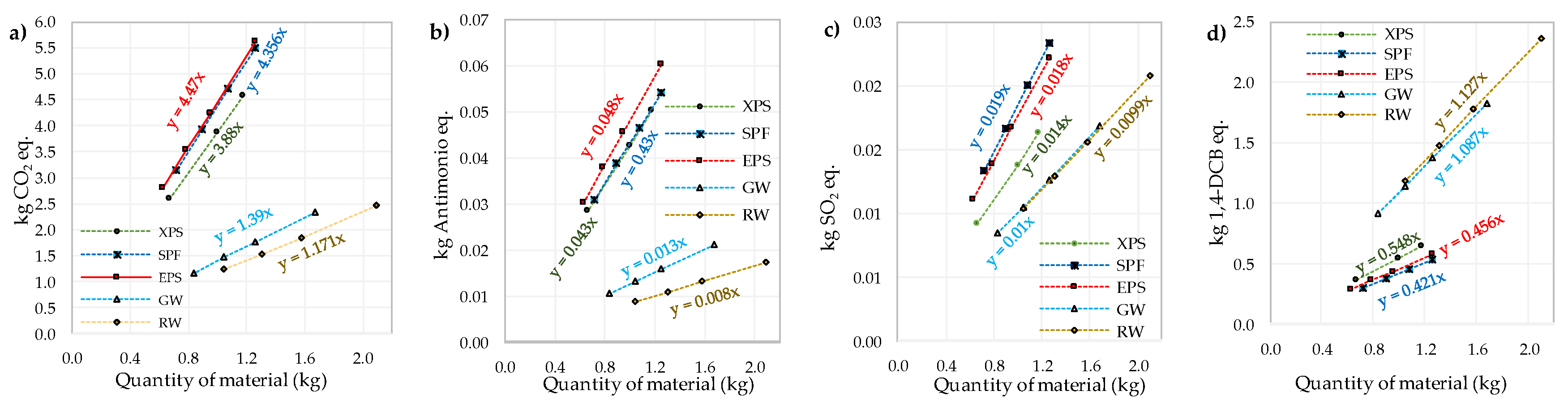
6. Prediction of the Environmental Behavior of E Components

To establish the predictive behavior of the environmental effect that may be generated by the different possible combinations of the components studied here, a statistical analysis of the information obtained from the LCA was carried out, and the regression equations were determined by means of numerical analysis.
The relationships between the quantity of material used in making the external walls and the generation of indicators for each impact category studied are shown in Figure 6 and Figure 7; from these, the impact increase rates (IIR, by establishing linear regression equations) were obtained for each type of material used in each component of the external walls. The general behavior of all of the studied variables is of a linear increase in the equivalent substance of each indicator with the increase of the mass quantity of the material to be used (linear relationship).
Once the linear regression models of each indicator have been established, the general equation integrative (GEI, Equation (7)) can be proposed. This permits the estimation of the integrated behavior of the different external walls that use the conventional spectrum of the proposed building materials. In this equation, the independent variables are the quantity of materials (in kg) that are used to make up the exterior layers (a), interior layers (b), and thermal insulations (c). The dependent variable is the quantity of CO2 eq. (Figure 6a and Figure 7a), kg of antimony eq. (Figure 6b and Figure 7b), kg of SO2 eq. (Figure 6c and Figure 7c), kg of PO4 (Figure 6d) or kg of 1.4-DCB eq. (Figure 6e and Figure 7d), which is generated by each component of the external wall. Table 4 includes the coefficients of the linear regressions that provide a solution for the GEI and the R2 coefficients obtained in order to make a prediction of the environmental impact of the five impact categories analyzed.
GEI = ax + by + cz + d
where: a, b, and c are obtained from Table 4; d is determined with the equation:
d =   d 1 +   d 2 +   d 3
where: d1, d2, and d3 are obtained from Table 4.
The GEI allows an environmental profile to be obtained simply and practically of any element to be used, either in the design or recovery (or maintenance) of a building, by selecting one or more of the materials included in this study.

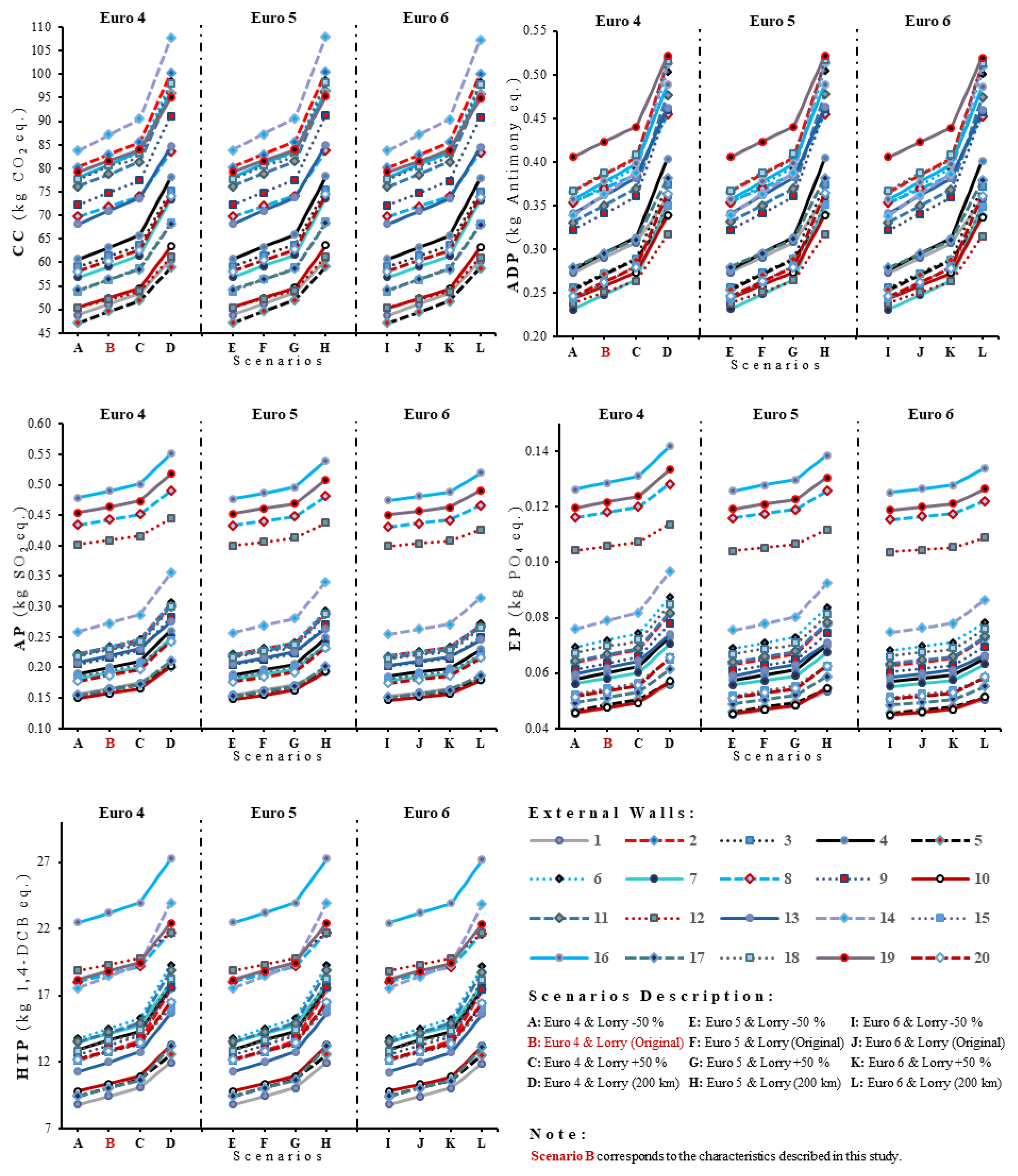
7. Sensitivity and Uncertainty Analysis

In LCA studies, merging sensitivity and uncertainty analysis are used to assess the robustness of the results and their sensitivity to data, assumptions, and models [95]. The relevance of this analyses has been pointed out by several researchers [50,95,96,97,98,99,100,101], which contribute to focused research efforts and also provide support in the interpretation of LCA study results [102], particularly in studies when the input data of the LCI has not been documented or are unreliable [100,103].
In this study, the information related to the input data comes from assured sources, which are widely used in the daily practice of the construction industry. Also, the processes considered correspond to what is stipulated by the Europe normative, which substantially reduces the uncertainty because the information is sufficiently available, in addition to the use of the Ecoinvent database already recognizing uncertainty in their probability distributions [95,100,102,103]. Due to the above, and because the present study considers the cradle to handover approach, the stage that could present a higher degree of uncertainty in data collection is the transport from the manufacturing plants to the construction site (A4).
With the aim of determining the environmental and human health effects caused by the extension of uncertainty propagation produced by the A4 stage, this study considers several combinations between the locations of the manufacturing plants and different ecological performances of the machines used for the transportation of materials at the construction sites (Table 5). Previous studies [50] have presented similar approaches in conducting sensitivity analyses.
For the location of the manufacturing plants, the distances used in this work that are taken as a reference are called "lorry"; from these, three alternatives are analyzed: lorry ±50% of the distances, and 200 km. On the other hand, the behavior of Euro 5 and Euro 6 engines [104] are compared with Euro 4, which generates a total of 11 more scenarios than the base scenarios (scenarios B).
According to sensitivity analysis, results vary in relation to the function of the indicator. The same occurs with the uncertainty percent that is presented in each of the cases according to the different scenarios considered, in which: (i) CC shows values between 7.37% (case 8) and 10.65% (case 7); (ii) ADP shows values from 10.25% (case 8) to 17.70% (case 7); (iii) AP shows values from 3.64% (case 12) to 11.94% (case 6); (iv) EP shows values from 2.96% (case 12) to 8.75% (case 2); and finally, (v) HTP shows values from 5.69% (case 12) to 15.37% (case 2).
The analysis highlights the relevance of the consideration of the A4 stage in the LCA, because the results obtained by the external walls in the different scenarios (Figure 8) show significant variations, which can mean increases of up to 42.18% and reductions of up to 8.06% in the environmental impacts produced during stages involved in the cradle to handover approach (A1–A5). The ADP and AP categories are those that present the most significant changes.
In terms of the ADP category, in which the largest increases occurred, the changes produced in scenario H in relation to scenario B show different variations in the interpretation of the original results; e.g., external wall 7 (which presented the best environmental performance in scenario B), would be 10.15% more polluting than external wall 12 (which presented the best environmental performance in scenario H). Also, consider external wall 8, which went from producing 14.11% less environmental impact than the case with the worst environmental performance in scenario B to producing only 1.57% less environmental impact than the case with the worst environmental performance in scenario H. In the case of both scenarios, the external wall with the worst environmental performance is external wall 19. On the other hand, in scenario H, the external wall 3 would not be considered between the external walls with the best environmental performance, because the impacts produced would be higher than 15% of those produced by the external wall 12.
Regarding the AP, the category in which the most significant reductions occurred, the position of each external wall in relation to the others was not affected. However, in this category, together with EP, the change from the Euro 4 engine to the Euro 6 engine exhibited more significant reductions in the environmental performance of the external walls.
Figure 8 also shows that variations in the locations of the manufacturing plants have a more significant impact than changes in the motorization of the machines used for transportation, except for the AP and EP categories, in which, the change from the Euro 4 engine to the Euro 6 engine generates reductions between 0.19–1.33% despite increasing the distances in the locations of the manufacturing plants by 50%. EP is the category with the most significant reductions; nevertheless, when the external walls consider scenario H, the increments varied between 2.90–9.80% in the EP, and 4.31–15.81% in the AP. Future studies could analyze the distance in which the change from the Euro 4 engine to the Euro 6 engine stops producing reductions in the environmental behavior of the external walls.
Among the results obtained by sensitivity analysis, it underlines that there is an increase in environmental performance only in the CC and ADP categories when changing from the Euro 4 engine to the Euro 5 engine. This increase varies between 0.04–0.13%; CC is the category in which the most substantial increases occur. Notwithstanding the above, general results support that renewing the vehicle fleet is an effective strategy to reduce its pollution effects [50,105,106], because all of the cases present reductions when the change is from the Euro 4 engine to the Euro 6 engine.

8. Conclusions

This study has made a comparison of the life cycle in stages A1–A5 of external walls conventionally used in Spanish residential buildings. The use of LCA established significant derivations among the considered perspectives, showing itself to be an efficient instrument for promoting sustainability in the construction industry.
The stages with the greatest environmental impact in all of the categories were A1–A3, which were more aggravating in EP (93.2%) and CC (92.3%). In stages A4–A5, the ADP and AP presented the highest values (11.4% and 0.32%, respectively for A4 and A5). Although transport (A4) depends on specific conditions, it makes a considerable contribution to the impacts in the life cycle. This can be verified in the studies that analyze it. Stage A4 can contribute to the reduction of the total environmental load by selecting materials available close to the construction site.
The external walls with the best general environmental profiles were 1, 3, 5, 7, 10, 15, 17, and 20. Although all of the systems are relatively equivalent, the external walls that could be recommended as ideal are 7, 10, 3, 17, 1, and 5 (in decreasing order with respect to U-value) because they generate the lowest environmental load and have the best U-values. On the contrary, the most damaging combination of elements is that which includes an exterior small-format layer and an interior layer of LPB. The walls with this combination are 16, 19, and 8 (in increasing order of U-value).
This study leads to the conclusion that a selection of elements with better physical capacities can in turn generate a lower environmental load. Therefore, the selection of elements and materials will be a determining factor in environmental optimization.
In the design of the external walls (choice of materials), simple strategies have been established in order to reduce their environmental repercussions. These include the use of large-format pieces (mortar or clay), which reduce the quantity of materials that are needed for making the wall pieces and the binders used in their assembly (mor), and the controlled increase in the thickness of the thermal insulation. Although individually, the thermal insulation does have an important impact compared with the rest of the components, with regard to the external wall, this is moderate.
When making a comparison between the materials that make up each layer of the external wall, it was found that: (i) the exterior layers made with ceramic clay pieces are more harmful than those made of mortar pieces in CC (1.14) and ADP (1.5). On the contrary, the walls made with mortar pieces generate more HTP than those made with ceramic clay pieces (1.4); (ii) the interior layers made with LPB are more harmful than those made with ceramic clay pieces (HTP: 2.5, AP: 5.3, EP: 3.7), this value is 80% due to the galvanized steel profile; and (iii) the thermal insulations made from hydrocarbons are more harmful than those from natural wool in all of the categories (CC: 2.3, ADP: 3, AP: 1.15), except in HTP (3.4).
The prediction of the environmental behavior (simulation equation) allows the possible impacts that the external walls may generate in the product stage to be studied with facility. This provides a useful tool for those in charge of planning in the search for more environmentally-friendly options, without detriment to the performance of the components.
The sensitivity and uncertainty analysis indicate that stage A4 performs a significant role in reducing emissions within the cradle to handover life cycle. Also, further research studies could be done with a more robust sensitivity and uncertainty analysis to support the conclusions or implications of the present study.
Finally, as well as evaluating the data of the characterization of the model used, an analysis would be needed of the impact of each of the categories involved (but from a comparative perspective) to thereby establish the impact at different levels (national, European, or global). To achieve this, it would be necessary to carry out a normalization of the impact categories with updated impact data. Similarly, a weighting of each of the impact categories would be of interest for establishing the importance that the construction of different external walls has for them.

Author Contributions

Methodology, D.C.G.G., J.M.G.S., R.C.H.; Writing original, D.C.G.G., J.M.G.S.; Validation, M.C.G.S.; S.P.A.R.; Formal Analysis, D.C.G.G., J.M.G.S., H.S.M.; Investigation, J.M.G.S.; Resources, J.M.G.S.; Data Curation, D.C.G.G., H.S.M.; Writing-Review & Editing, R.C.H.; M.C.G.S.; Supervision, J.M.G.S., R.C.H.; S.P.A.R.

Acknowledgments

The authors would like to thank CONACYT for its doctoral scholarship program, the Barcelona School of Building Construction-UPC, the Department of Architecture Technology-EPSEB-UPC and the School of Engineering Mochis-UAS.

Conflicts of Interest

The authors declare no conflict of interest.

Abbreviations

A1–A3Product stage
A4Transport from factory to site
A4–A5Construction process stage
A5Construction process/installation stage
ADPDepletion of abiotic resources
CCClimate change
CCPCeramic clay pieces
ELExterior layer
EPEutrophication potential
EPSExpanded polystyrene
EWExternal walls
GLaminated plasterboard
GWGlass wool
HBdDouble hollow brick
HBsSingle hollow brick
HRHeight of reference
HTPHuman toxicity
ILInterior layer
LCALife cycle assessment
LCILife cycle inventory
LFPHollow large format
LFPpPerforated large format partition wall
LPBLaminated plasterboard
MBHollow mortar block
morMortar
MPMortar pieces
ODPStratospheric ozone depletion
PBPerforated brick
POCPPhotochemical oxidation
RWRock wool
SMBSolid mortar brick
SPFSpray Polyurethane Foam
TIThermal insulation
XPSExtruded polystyrene

References

  1. Huedo, P.; Mulet, E.; López-Mesa, B. A model for the sustainable selection of building envelope assemblies. Environ. Impact Assess. Rev. 2016, 57, 63–77. [Google Scholar] [CrossRef] [Green Version]
  2. Tsai, W.H.; Lin, S.J.; Liu, J.Y.; Lin, W.R.; Lee, K.C. Incorporating life cycle assessments into building project decision-making: An energy consumption and CO2 emission perspective. Energy 2011, 36, 3022–3029. [Google Scholar] [CrossRef]
  3. Cabeza, L.F.; Rincón, L.; Vilariño, V.; Pérez, G.; Castell, A. Life cycle assessment (LCA) and life cycle energy analysis (LCEA) of buildings and the building sector: A review. Renew. Sustain. Energy Rev. 2014, 29, 394–416. [Google Scholar] [CrossRef]
  4. Han, B.; Wang, R.; Yao, L.; Liu, H.; Wang, Z. Life cycle assessment of ceramic façade material and its comparative analysis with three other common façade materials. J. Clean. Prod. 2015, 99, 86–93. [Google Scholar] [CrossRef] [Green Version]
  5. Lei, J.; Yang, J.; Yang, E.-H. Energy performance of building envelopes integrated with phase change materials for cooling load reduction in tropical Singapore. Appl. Energy 2016, 162, 207–217. [Google Scholar] [CrossRef]
  6. Zhang, T.; Tan, Y.; Yang, H.; Zhang, X. The application of air layers in building envelopes: A review. Appl. Energy 2016, 165, 707–734. [Google Scholar] [CrossRef]
  7. Kofoworola, O.F.; Gheewala, S.H. Life cycle energy assessment of a typical office building in Thailand. Energy Build. 2009, 41, 1076–1083. [Google Scholar] [CrossRef]
  8. Ortiz, O.; Bonnet, C.; Bruno, J.C.; Castells, F. Sustainability based on LCM of residential dwellings: A case study in Catalonia, Spain. Build. Environ. 2009, 44, 584–594. [Google Scholar] [CrossRef]
  9. Mirrahimi, S.; Farid, M.; Chin, L. The effect of building envelope on the thermal comfort and energy saving for high-rise buildings in hot-humid climate. Renew. Sustain. Energy Rev. 2016, 53, 1508–1519. [Google Scholar] [CrossRef]
  10. Chang, Y.; Ries, R.J.; Wang, Y. The quantification of the embodied impacts of construction projects on energy, environment, and society based on I-O LCA. Energy Policy 2011, 39, 6321–6330. [Google Scholar] [CrossRef]
  11. Gong, X.; Nie, Z.; Wang, Z.; Cui, S.; Gao, F.; Zuo, T. Life cycle energy consumption and carbon dioxide emission of residential building designs in Beijing: A comparative study. J. Ind. Ecol. 2012, 16, 576–587. [Google Scholar] [CrossRef]
  12. Ortiz, O.; Pasqualino, J.C.; Díez, G.; Castells, F. The environmental impact of the construction phase: An application to composite walls from a life cycle perspective. Resour. Conserv. Recycl. 2010, 54, 832–840. [Google Scholar] [CrossRef]
  13. Radhi, H.; Sharples, S. Global warming implications of facade parameters: A life cycle assessment of residential buildings in Bahrain. Environ. Impact Assess. Rev. 2013, 38, 99–108. [Google Scholar] [CrossRef]
  14. Ramesh, T.; Prakash, R.; Shukla, K.K. Life cycle energy analysis of buildings: An overview. Energy Build. 2010, 42, 1592–1600. [Google Scholar] [CrossRef]
  15. Scheuer, C.; Keoleian, G.A.; Reppe, P. Life cycle energy and environmental performance of a new university building: Modeling challenges and design implications. Energy Build. 2003, 35, 1049–1064. [Google Scholar] [CrossRef]
  16. Zabalza-Bribián, I.; Valero-Capilla, A.; Aranda-Usón, A. Life cycle assessment of building materials: Comparative analysis of energy and environmental impacts and evaluation of the eco-efficiency improvement potential. Build. Environ. 2011, 46, 1133–1140. [Google Scholar] [CrossRef]
  17. Zhang, X.; Shen, L.; Zhang, L. Life cycle assessment of the air emissions during building construction process: A case study in Hong Kong. Renew. Sustain. Energy Rev. 2013, 17, 160–169. [Google Scholar] [CrossRef]
  18. Dowd, R.M.; Mourshed, M. Low carbon Buildings: Sensitivity of Thermal Properties of Opaque Envelope Construction and Glazing. Energy Procedia 2015, 75, 1284–1289. [Google Scholar] [CrossRef]
  19. Spanish Association for Standardization and Certification. UNE-EN 15804:2012+A1. Sustainability of Construction Works-Environmental Product Declarations. Core Rules for the Product Category of Construction Products; AENOR: Madrid, Spain, 2014. [Google Scholar]
  20. Sartori, I.; Hestnes, A.G.G. Energy use in the life cycle of conventional and low-energy buildings: A review article. Energy Build. 2007, 39, 249–257. [Google Scholar] [CrossRef]
  21. Bilec, M.M.; Ries, R.J.; Matthews, H.S. Life-Cycle Assessment Modeling of Construction Processes for Buildings. J. Infrastruct. Syst. 2010, 16, 199–205. [Google Scholar] [CrossRef]
  22. Blengini, G.A.; Di-Carlo, T. The changing role of life cycle phases, subsystems and materials in the LCA of low energy buildings. Energy Build. 2010, 42, 869–880. [Google Scholar] [CrossRef]
  23. Iddon, C.R.; Firth, S.K. Embodied and operational energy for new-build housing: A case study of construction methods in the UK. Energy Build. 2013, 67, 479–488. [Google Scholar] [CrossRef]
  24. Pal, S.K.; Takano, A.; Alanne, K.; Palonen, M.; Siren, K. A multi-objective life cycle approach for optimal building design: A case study in Finnish context. J. Clean. Prod. 2017, 143, 1021–1035. [Google Scholar] [CrossRef]
  25. Ottelé, M.; Perini, K.; Fraaij, A.L.A.; Haas, E.M.; Raiteri, R. Comparative life cycle analysis for green facades and living wall systems. Energy Build. 2011, 43, 3419–3429. [Google Scholar] [CrossRef]
  26. Chwieduk, D.A. Some aspects of energy efficient building envelope in high latitude countries. Solar Energy 2016, 133, 194–206. [Google Scholar] [CrossRef]
  27. Friess, W.A.; Rakhshan, K.; Hendawi, T.A.; Tajerzadeh, S. Wall insulation measures for residential villas in Dubai: A case study in energy efficiency. Energy Build. 2012, 44, 26–32. [Google Scholar] [CrossRef]
  28. Serrano, A.; Borreguero, A.M.; Garrido, I.; Rodríguez, J.F.; Carmona, M. Reducing heat loss through the building envelope by using polyurethane foams containing thermoregulating microcapsules. Appl. Therm. Eng. 2016, 103, 226–232. [Google Scholar] [CrossRef]
  29. Thormark, C. The effect of material choice on the total energy need and recycling potential of a building. Build. Environ. 2006, 41, 1019–1026. [Google Scholar] [CrossRef]
  30. Venkatarama-Reddy, B.V.; Jagadish, K.S. Embodied energy of common and alternative building materials and technologies. Energy Build. 2003, 35, 129–137. [Google Scholar] [CrossRef]
  31. Roh, S.; Tae, S.; Kim, R. Analysis of embodied environmental impacts of Korean apartment buildings considering major building materials. Sustainability 2018, 10, 1693. [Google Scholar] [CrossRef]
  32. Hastak, M.; Halpin, D.W. Assessment of life-cycle benefit-cost of composites in construction. J. Compos. Constr. 2000, 4, 103–111. [Google Scholar] [CrossRef]
  33. Hastak, M.; Mirmiran, A.; Richard, D. A framework for life-cycle cost assessment of composites in construction. J. Reinf. Plast. Compos. 2003, 22, 1409–1430. [Google Scholar] [CrossRef]
  34. Hu, M.; Kleijn, R.; Bozhilova-Kisheva, K.P.; Di-Maio, F. An approach to LCSA: The case of concrete recycling. Int. J. Life Cycle Assess. 2013, 18, 1793–1803. [Google Scholar] [CrossRef]
  35. Finkbeiner, M.; Schau, E.M.; Lehmann, A.; Traverso, M. Towards Life Cycle Sustainability Assessment. Sustainability 2010, 2, 3309–3322. [Google Scholar] [CrossRef]
  36. Kloepffer, W. Life Cycle Sustainability Assessment of Products. Int. J. Life Cycle Assess. 2008, 13, 89–95. [Google Scholar] [CrossRef]
  37. Erlandsson, M.; Borg, M. Generic LCA-methodology applicable for buildings, constructions and operation services—today practice and development needs. Build. Environ. 2003, 38, 919–938. [Google Scholar] [CrossRef]
  38. Kellenberger, D.; Althaus, H.-J. Relevance of simplifications in LCA of building components. Build. Environ. 2009, 44, 818–825. [Google Scholar] [CrossRef]
  39. Ortiz, O.; Castells, F.; Sonnemann, G. Sustainability in the construction industry: A review of recent developments based on LCA. Constr. Build. Mater. 2009, 23, 28–39. [Google Scholar] [CrossRef]
  40. Xing, S.; Xu, Z.; Jun, G. Inventory analysis of LCA on steel- and concrete-construction office buildings. Energy Build. 2008, 40, 1188–1193. [Google Scholar] [CrossRef]
  41. Zhang, Z.; Wu, X.; Yang, X.; Zhu, Y. BEPAS—A life cycle building environmental performance assessment model. Build. Environ. 2006, 41, 669–675. [Google Scholar] [CrossRef]
  42. Gervasio, H.; Dimova, S.; Pinto, A. Benchmarking the life-cycle environmental performance of buildings. Sustainability 2018, 10, 1454. [Google Scholar] [CrossRef]
  43. Seo, S.; Passer, A.; Zelezna, J.; Hajek, P.; Birgisdottir, H.; Rasmussen, F.N.; Lützkendorf, T.; Balouktsi, M.; Mistretta, M.; Oka, T.; et al. Overview of annex 57 results. In Evaluation of Embodied Energy and CO2eq for Building Construction (Annex 57); Yokoo, N., Yokoyama, K., Eds.; IEA: Tokio, Japan, 2016; pp. 1–90. ISBN 9784909107107. [Google Scholar]
  44. Gardezi, S.S.S.; Shafiq, N.; Zawawi, N.A.W.A.; Khamidi, M.F.; Farhan, S.A. A multivariable regression tool for embodied carbon footprint prediction in housing habitat. Habitat Int. 2016, 53, 292–300. [Google Scholar] [CrossRef]
  45. Robertson, A.B.; Lam, F.C.F.; Cole, R.J. A comparative cradle-to-gate life cycle assessment of mid-rise office building construction alternatives: laminated timber or reinforced concrete. Buildings 2012, 2, 245–270. [Google Scholar] [CrossRef]
  46. Jia-Wen, T.; Chin-Siong, H.; Noor, Z.Z. Assessment of embodied energy and global warming potential of building construction using life cycle analysis approach: Case studies of residential buildings in Iskandar Malaysia. Energy Build. 2015, 93, 295–302. [Google Scholar] [CrossRef]
  47. Chang, Y.; Ries, R.J.; Lei, S. The embodied energy and emissions of a high-rise education building: A quantification using process-based hybrid life cycle inventory model. Energy Build. 2012, 55, 790–798. [Google Scholar] [CrossRef]
  48. Sandanayake, M.; Lokuge, W.; Zhang, G.; Setunge, S.; Thushar, Q. Greenhouse gas emissions during timber and concrete building construction—A scenario based comparative case study. Sustain. Cities Soc. 2018, 38, 91–97. [Google Scholar] [CrossRef]
  49. Cass, D.; Mukherjee, A. Calculation of greenhouse gas emissions for highway construction operations by using a hybrid life-cycle assessment approach: case study for pavement operations. J. Constr. Eng. Manag. 2011, 137, 1015–1026. [Google Scholar] [CrossRef]
  50. Moretti, L.; Mandrone, V.; Andrea, A.D.; Caro, S. Evaluation of the environmental and human health impact of road construction activities. J. Clean. Prod. 2018, 172, 1004–1013. [Google Scholar] [CrossRef]
  51. Smith, S.H.; Durham, S.A. A cradle to gate LCA framework for emissions and energy reduction in concrete pavement mixture design. Int. J. Sustain. Built Environ. 2016, 5, 23–33. [Google Scholar] [CrossRef]
  52. Moretti, L.; Mandrone, V.; Andrea, A.D.; Caro, S. Comparative “from cradle to gate” life cycle assessments of hot mix asphalt (HMA) materials. Sustainability 2017, 9, 400. [Google Scholar] [CrossRef]
  53. Asdrubali, F.; Baldassarri, C.; Fthenakis, V. Life cycle analysis in the construction sector: Guiding the optimization of conventional Italian buildings. Energy Build. 2013, 64, 73–89. [Google Scholar] [CrossRef]
  54. Bovea, M.D.; Díaz-Albo, E.; Gallardo, A.; Colomer, F.J.; Serrano, J. Environmental performance of ceramic tiles: Improvement proposals. Mater. Des. 2010, 31, 35–41. [Google Scholar] [CrossRef]
  55. Ecoinvent Centre. Home Page of Ecoinvent, Dübendorf, Suiza. 2007. Available online: https://www.ecoinvent.org/database/introduction-to-ecoinvent-3/introduction-to-ecoinvent-version-3.html (accessed on 2 August 2018).
  56. Heinonen, J.; Säynäjoki, A.; Junnonen, J.M.; Pöyry, A.; Junnila, S. Pre-use phase LCA of a multi-story residential building: Can greenhouse gas emissions be used as a more general environmental performance indicator? Build. Environ. 2016, 95, 116–125. [Google Scholar] [CrossRef] [Green Version]
  57. Ortiz, O.; Pasqualino, J.C.; Castells, F. Environmental performance of construction waste: Comparing three scenarios from a case study in Catalonia, Spain. Waste Manag. 2010, 30, 646–654. [Google Scholar] [CrossRef] [PubMed]
  58. Thiers, S.; Peuportier, B. Energy and environmental assessment of two high energy performance residential buildings. Build. Environ. 2012, 51, 276–284. [Google Scholar] [CrossRef]
  59. Ferrández-García, A.; Ibáñez-Forés, V.; Bovea, M.D. Eco-efficiency analysis of the life cycle of interior partition walls: A comparison of alternative solutions. J. Clean. Prod. 2016, 112, 649–665. [Google Scholar] [CrossRef]
  60. ITEC, Metabase—Banco BEDEC 2017. ITEC Web. 2017. Available online: https://metabase.itec.cat/vide/es/bedec (accessed on 3 January 2017).
  61. Pre’ Consultants, SimaPro Database Manual-Methods Library, California, USA. 2018. Available online: https://www.pre-sustainability.com/download/manuals/DatabaseManualMethods.pdf (accessed on 2 August 2018).
  62. Potting, J.; Klöpffer, W.; Seppälä, J.; Norris, G.; Goedkoop, M. Climate Change, Stratospheric Ozone Depletion, Photooxidant Formation, Acidification, and Eutrophication. In Life-Cycle Impact Assessement: Striving towards Best Practice; Udo-de-Haes, H.A., Finnveden, G., Goedkoop, M., Hauschild, M., Hertwich, E., Hofstetter, P., Jolliet, O., Klöpffer, W., Krewitt, W., Lindeijer, E., Eds.; SETAC: Florida City, FL, USA, 2002; pp. 65–100. ISBN 1880611546. [Google Scholar]
  63. Lindeijer, E.; Müller-Wenk, R.; Steen, B. Impact Assessment of Resources and Land Use. In Life-Cycle Impact Assessement: Striving Towards Best Practice; Udo-de-Haes, H.A., Finnveden, G., Goedkoop, M., Hauschild, M., Hertwich, E., Hofstetter, P., Jolliet, O., Klöpffer, W., Krewitt, W., Lindeijer, E., et al., Eds.; SETAC: Florida City, FL, USA, 2015; pp. 11–64. ISBN 1880611546. [Google Scholar]
  64. Ministerio de Agricultura y Pesca, Alimentación y Medio Ambiente, Sustancias que Agotan la capa de Ozono. 2017. Available online: http://www.mapama.gob.es/es/calidad-y-evaluacion-ambiental/temas/atmosfera-y-calidad-del-aire/emisiones/prob-amb/agotadores_capa_ozono.aspx (accessed on 17 May 2017).
  65. Jolliet, O.; Fantke, P. Human Toxicity. In Life Cycle Impact Assessment; Hauschild, M.Z., Huijbregts, M.A.J., Eds.; Springer: Dordrecht, The Netherlands, 2015; pp. 75–96. ISBN 978-94-017-9743-6. [Google Scholar]
  66. Simpple, Manual de Usuario LCA Manager Versión 1.3, Tarragona, Spain. 2010. Available online: http://www.simpple.com/wp-content/uploads/2013/12/Manual_LCAm.pdf (accessed on 2 August 2018).
  67. Spanish Association for Standardization and Certification. UNE-EN ISO 14040. Environmental Management. Life Cycle Assessment-Principles and Framework; AENOR: Madrid, Spain, 2006. [Google Scholar]
  68. Departament d´Estadística. Ajuntament de Barcelona, Características de los Edificios Destinados Principalmente a Vivienda. 2011. Available online: http://www.bcn.cat/estadistica/castella/dades/timm/censedif/a2011/princhabit/t21.htm (accessed on 5 April 2018).
  69. AMB, Ordenances D’aplicació a Tota la Zona Metropolitana. 2010. Available online: http://www3.amb.cat/normaurb2004/Docs/Edificacio/OME-T2-C1-S1.pdf (accessed on 13 May 2017).
  70. CTE, Documento Básico HE Ahorro de Energía, Boletín Oficial del Estado, Spain. 2013. Available online: https://www.codigotecnico.org/images/stories/pdf/ahorroEnergia/DBHE.pdf (accessed on 2 August 2018).
  71. Spanish Association for Standardization and Certification. UNE-EN 771-1. Specification for Masonry Units. Part 1: Clay Masonry Units; AENOR: Madrid, Spain, 2011. [Google Scholar]
  72. Spanish Association for Standardization and Certification. UNE-EN 771-3. Specification for Masonry Units. Part 3: Aggregate Concrete Masonry Units (Dense and Lightweight Aggregates); AENOR: Madrid, Spain, 2011. [Google Scholar]
  73. Spanish Association for Standardization and Certification. UNE-EN 520:2005+A1. Gypsum Plasterboards. Definitions, Requirements and Test Methods; AENOR: Madrid, Spain, 2010. [Google Scholar]
  74. Spanish Association for Standardization and Certification. UNE-EN 13162:2013+A1. Thermal Insulating Products for Building Applications. Manufactured Products of Mineral Wool (MW). Specification; AENOR: Madrid, Spain, 2015. [Google Scholar]
  75. Spanish Association for Standardization and Certification. UNE-EN 13163:2013+A1. Thermal Insulating Products for Building Applications. Manufactured Products of Expanded Polystyrene (EPS). Specification; AENOR: Madrid, Spain, 2013. [Google Scholar]
  76. Spanish Association for Standardization and Certification. UNE-EN 13164:2013+A1. Thermal Insulating Products for Building Applications. Products Manufactured from Extruded Polystyrene (XPS). Specification; AENOR: Madrid, Spain, 2015. [Google Scholar]
  77. Spanish Association for Standardization and Certification. UNE-EN 14315. Thermal Insulating Products for Building Applications. Products of Rigid Polyurethane Foam and Polyisocyanurate Projected In Situ. Part 1: Specifications for Rigid Foam Projection Systems before Installation; AENOR: Madrid, Spain, 2013. [Google Scholar]
  78. Spanish Association for Standardization and Certification. UNE-EN 998-1:2010. Specification for Mortar for Masonry. Part 1: Rendering and Plastering Mortar; AENOR: Madrid, Spain, 2010. [Google Scholar]
  79. CTE WEB, Código Técnico la Edificación. 2007. Available online: http://cte-web.iccl.es/ (accessed on 8 May 2017).
  80. Spanish Association for Standardization and Certification. UNE-EN 13501-1:2007+A1:2010. Fire Classification of Construction Products and Building Elements. Part 1: Classification Using Data from Reaction to Fire Tests; AENOR: Madrid, Spain, 2010. [Google Scholar]
  81. ATEPA, Libro Blanco del Poliuretano Proyectado. Guía de Ventajas y Soluciones de Espuma Rígida de Poliuretano Proyectado Para Aislamiento Térmico, Acústico e Impermeabilización, Conforme al CTE, Asociación Técnica del Poliuretano Aplicado, Madrid, Spain. 2010. Available online: http://www.atepa.org/PUR.pdf (accessed on 2 August 2018). [CrossRef]
  82. IDAE, Soluciones de Aislamiento con Poliestireno Expandido (EPS), Instituto Para la Diversificación y Ahorro de Energía, Madrid, Spain. 2008. Available online: http://www.idae.es/publicaciones/soluciones-de-aislamiento-con-poliestireno-expandido-eps (accessed on 2 August 2018).
  83. IDAE, Soluciones de Aislamiento con Poliestireno Extruido (XPS), Instituto Para la Diversificación y Ahorro de Energía, Madrid, Spain. 2008. Available online: http://www.idae.es/publicaciones/soluciones-de-aislamiento-con-poliestireno-extruido-xps (accessed on 2 August 2018).
  84. Ministerio de Fomento, Inspección y Seguridad en el Transporte—Pesos y Dimensiones. 2017. Available online: https://www.fomento.gob.es/MFOM/LANG_CASTELLANO/DIRECCIONES_GENERALES/TRANSPORTE_TERRESTRE/IGT/PESO/ (accessed on 12 January 2017).
  85. Hauschild, M.Z.; Huijbregts, M.A.J. Introducing the Life Cycle Impact Assessment. In Life Cycle Assessment; Hauschild, M.Z., Huijbregts, M.A.J., Eds.; Springer: Dordrecht, The Netherlands, 2015; pp. 1–16. [Google Scholar] [CrossRef]
  86. Morales-Güeto, J. El Proceso de Elaboración Cerámico: Tecnología de los Materiales Cerámicos, 1st ed.; Ediciones Díaz de Santos: Madrid, Spain, 2005; pp. 237–321. ISBN 978-8479787226. [Google Scholar]
  87. Damtoft, J.S.; Lukasik, J.; Herfort, D.; Sorrentino, D.; Gartner, E.M. Sustainable development and climate change initiatives. Cem. Concr. Res. 2008, 38, 115–127. [Google Scholar] [CrossRef]
  88. Bustillo-Revuelta, M. Hormigones y Morteros; Fueyo Editores: Madrid, Spain, 2008; pp. 104–166. ISBN 978-84-935279-1-4. [Google Scholar]
  89. EEA, Acidificación. El Medio Ambiente en Europa: Segunda Evaluación; EEA, Ed.; European Environment Agency: Copenhagen, Denmark, 1998; pp. 72–93. Available online: https://www.eea.europa.eu/es/publications/92-828-3351-8/4es.pdf/view (accessed on 2 August 2018).
  90. Flower, D.J.M.; Sanjayan, J.G. Green house gas emissions due to concrete manufacture. Int. J. Life Cycle Assess. 2007, 12, 282–288. [Google Scholar] [CrossRef]
  91. Broun, R.; Menzies, G.F. Life cycle energy and environmental analysis of partition wall systems in the UK. Procedia Eng. 2011, 21, 864–873. [Google Scholar] [CrossRef]
  92. Boesch, M.E.; Koehler, A.; Hellweg, S. Model for cradle-to-gate life cycle assessment of clinker production. Environ. Sci. Technol. 2009, 43, 7578–7583. [Google Scholar] [CrossRef] [PubMed]
  93. Centro Nacional de Referencia Sobre Contaminantes Orgánicos Persistentes, Hornos de Cemento que Queman Desechos Peligrosos. 2018. Available online: http://www.cnrcop.es/gc/iniciativas-no-gubernamentales/mejores-tecnicas-disponibles-mtd-y-mejores-practicas-ambientales-mpa/mejores-tecnicas-disponibles-mtd-y-mejores-practicas-ambientales-mpa/hornos-de-cemento-que-queman-desechos-peligrosos/ (accessed on 13 January 2018).
  94. Utama, N.A.; Mclellan, B.C.; Gheewala, S.H.; Ishihara, K.N. Embodied impacts of traditional clay versus modern concrete houses in a tropical regime. Build. Environ. 2012, 57, 362–369. [Google Scholar] [CrossRef]
  95. Wei, W.; Larrey-Lassalle, P.; Faure, T.; Dumoulin, N.; Roux, P.; Mathias, J.D. How to conduct a proper sensitivity analysis in life cycle assessment: Taking into account correlations within LCI data and interactions within the LCA calculation model. Environ. Sci. Technol. 2015, 49, 377–385. [Google Scholar] [CrossRef] [PubMed]
  96. Huijbregts, M.A.J.; Gilijamse, W.; Ragas, A.M.J.; Reijnders, L. Evaluating uncertainty in environmental life-cycle assessment. A case study comparing two insulation options for a Dutch one-family dwelling. Environ. Sci. Technol. 2003, 37, 2600–2608. [Google Scholar] [CrossRef] [PubMed]
  97. Lloyd, S.M.; Ries, R. Characterizing, propagating, and analyzing uncertainty in life-cycle assessment. J. Ind. Ecol. 2007, 11, 161–181. [Google Scholar] [CrossRef]
  98. Gustavsson, L.; Joelsson, A. Life cycle primary energy analysis of residential buildings. Energy Build. 2010, 42, 210–220. [Google Scholar] [CrossRef]
  99. Pushkar, S. Using eco-indicator 99 to evaluate building technologies under life cycle assessment uncertainties. J. Archit. Eng. 2014, 20, 04013010. [Google Scholar] [CrossRef]
  100. Noshadravan, A.; Wildnauer, M.; Gregory, J.; Kirchain, R. Comparative pavement life cycle assessment with parameter uncertainty. Transp. Res. Part D Transp. Environ. 2013, 25, 131–138. [Google Scholar] [CrossRef]
  101. Groen, E.A.; Bokkers, E.A.M.; Heijungs, R.; de-Boer, I.J.M. Methods for global sensitivity analysis in life cycle assessment. Int. J. Life Cycle Assess. 2017, 22, 1125–1137. [Google Scholar] [CrossRef]
  102. Finnveden, G.; Hauschild, M.Z.; Ekvall, T.; Guinée, J.; Heijungs, R.; Hellweg, S.; Koehler, A.; Pennington, D.; Suh, S. Recent developments in Life Cycle Assessment. J. Environ. Manag. 2009, 91, 1–21. [Google Scholar] [CrossRef] [PubMed] [Green Version]
  103. Buyle, M.; Braet, J.; Audenaert, A. Life cycle assessment in the construction sector: A review. Renew. Sustain. Energy Rev. 2013, 26, 379–388. [Google Scholar] [CrossRef]
  104. Hooftman, N.; Oliveira, L.; Messagie, M.; Coosemans, T.; Mierlo, J.V. Environmental analysis of petrol, diesel and electric passenger cars in a Belgian urban setting. Energies 2016, 9, 84. [Google Scholar] [CrossRef]
  105. Höltl, A.; Macharis, C.; De-Brucker, K. Pathways to decarbonise the European car fleet: A scenario analysis using the backcasting approach. Energies 2018, 11, 20. [Google Scholar] [CrossRef]
  106. Longo, M.; Yaïci, W.; Zaninelli, D. “Team play” between renewable energy sources and vehicle fleet to decrease air pollution. Sustainability 2016, 8, 27. [Google Scholar] [CrossRef] [Green Version]
Figure 1. System boundaries of life cycle assessment (LCA).
Sustainability 10 02748 g001
Figure 2. Configuration of the external walls.
Sustainability 10 02748 g002
Figure 3. Percentages of the environmental damage of the average of the external walls in stages A1–A5 for all of the impact categories.
Sustainability 10 02748 g003
Figure 4. Total value of each indicator (a) climate change (CC), (b) depletion of abiotic resources (ADP), (c) acidification potential (AP), (d) eutrophication potential (EP), (e) human toxicity (HTP) in stages A1–A5 for each EW (EL + TI + IL).
Sustainability 10 02748 g004
Figure 5. Detail of the elements of the EWs (and materials) in stages A1–A3 for the (a) CC, (b) ADP, (c) HTP, and (d) AP and EP.
Sustainability 10 02748 g005
Figure 6. Linear regression for EL and IL in: (a) CC, (b) APD, (c) AP, (d) EP, and (e) HTP.
Sustainability 10 02748 g006
Figure 7. Linear regression for TI in: (a) CC, (b) APD, (c) AP, and (d) HTP.
Sustainability 10 02748 g007
Figure 8. Results from the sensitivity analysis.
Sustainability 10 02748 g008
Table 1. Properties of the external walls.
EW1234567891011121314151617181920
U-value (W/m2K)0.650.680.630.680.650.640.610.70.660.610.610.670.620.610.690.620.640.700.680.69
Thickness (cm)26.324.526.027.026.327.025.023.528.026.024.523.825.826.525.325.827.526.525.825.5
Table 2. Properties of materials used.
Element of Wall *Type *Material *** λ (W/mK)*** Fire ResistanceDensity (kg/m3)Characteristics
ELCCPPB0.35A-1780 **High-density (HD) CCP with faced finish (FF) joined with industrial mor M7.5; category I UNE-EN 771-1 [71].
LFPp0.23A-1850 ***HD CCP with coated finish (CF) joined with mor 1:2:10 of cement (CEM II); category I UNE-EN 771-1 [71].
MPMB1.18A-1520–1230 **MB pieces with CF joined with mixed mor 1:2:10; category I UNE-EN 771-3 [72].
SMB1.18A-1520–1230 **SMB pieces with CF joined with mixed mor 1:2:10; category I UNE-EN 771-3 [72].
ILCCPHBs0.32A-1770 **Low-density (LD) partitions with CF joined with mixed mor 1:2:10; UNE-EN 771-1 [71].
HBd0.32A-1770 **LD partitions with CF joined with mixed mor 1:2:10; UNE-EN 771-1 [71].
LFP0.29A-1650 **LD partitions of 700 × 500 mm and variable thickness with CF joined with gypsum-based adhesive; UNE-EN 771-1 [71].
LPBLPB0.25A-2 S-1, d0750–900 **Self-supporting structure of galvanized steel profiles (GP), uprights each 400 mm (60 mm width), channels (60 mm width) with laminated plasterboard (G); UNE-EN 520 [73].
TINatural woolRW0.035A-150 ****Rigid plate positioned without adhering, UNE-EN 13162 [74].
GW0.036A-140 ****Semi-rigid plate positioned without adhering; UNE-EN 13162 [74].
PetroleumEPS0.036B-S1, d010–50 **Smooth surface faces and smooth edge, without adhering; UNE-EN 13163 [75].
XPS0.036B-S1, d025–50 **Smooth surface faces and smooth edge, without adhering; UNE-EN 13164 [76].
SPF0.028B-S1, d030–60 **Spray polyurethane foam. Amorphous and projected; UNE-EN 14315-1 [77].
Finishesmor0.55A-11000–1300 **Mor CSIII W1 of 1.5 cm thickness. Mor CSIII W0 of 1.5 cm thickness; UNE-EN 998-1 [78].
G0.25A-2 S-1, d0750–900 **Adhered with gypsum base over its entire surface [73].
* See Figure 2 for the definition of acronyms;** λ = Thermal conductivity. Spanish building technical code (CTE) [79]; *** Technical sheet of local material supplier; **** Structured Bank of Constructive Elements Data (BEDEC) [60].
Table 3. Life cycle inventory for 1 m2 of each external wall (EW).
StageElementMaterial/ProcessExternal WallsEcoinvent Process/Material
1234567891011121314151617181920
A1–A3ELCeramic clay pieces (kg)91.6130.6--91.6109.4-114.5117.591.6109.4-119.9---91.6114.5130.6-Brick production, RER
Mortar pieces (kg)--149.5126.1--126.1----126.1 217.2149.5217.2---149.5Concrete block production, RER
Mortar (kg)42.3125.549.844.642.3115.744.6104.6112.042.3115.744.6100.977.149.877.142.3104.6125.549.8Cement mortar production, CH
ILCeramic clay pieces (kg)51.637.430.570.951.670.949.5-50.850.849.5-45.849.536.3-64.370.9-30.5Light clay brick production, DE
Mortar (kg)-43.341.352.8-52.858.6-37.037.058.6--58.6 -40.252.8-41.3Cement mortar production, CH
Laminated plasterboard (kg)9.5---9.5--13.3---9.59.5 9.59.5--9.5-Gypsum plasterboard production, RoW
Gypsum (kg)13.5---13.5--0.8---0.89.7 7.20.8--0.8-Stucco production, CH
Steel (kg)-------2.3---2.3---2.3--2.3-Steel production, converter, unalloyed, RER
Zinc (m2)-------1.1---1.1---1.1--1.1-Zinc coating, coils, RER
TIRW (kg)--------1.051.311.582.10--------Rock wool production, CH
GW (kg)----0.841.051.681.26------------Glass wool mat production, CH
EPS (kg)0.630.791.260.95----------------Polystyrene foam slab production, RER
XPS (kg)----------------0.670.671.001.18Polystyrene production, extruded, CO2 blown
SPF (kg)------------0.721.080.901.26----Polyurethane production, rigid foam, RER
A4EWLorry operation (tkm)28.032.126.930.028.133.927.625.631.224.231.320.933.139.929.833.226.134.027.927.0Transport, freight, lorry 16–32 metric ton, EURO4
A5EWMachine use (unit) (10E-7)1.903.072.482.681.903.182.552.152.892.033.041.682.613.672.302.802.173.122.452.47Building machine production
Energy (kWh) (10E-1)1.223.672.052.181.223.672.292.303.261.773.781.052.413.051.301.791.843.442.752.05Market for electricity, low voltage, ES
Table 4. Regression coefficients for the prediction of the general equation integrative (GEI) of the EWs.
CCADPHTPAPEP
ad1R2ad1R2ad1R2ad1R2ad1R2
CCP0.2251.5440.990.00080.03200.990.0300.3800.990.00060.00220.990.00020.00150.99
MP0.191−0.0800.990.00060.00000.990.0420.0420.990.00060.00000.990.00020.00001.00
bd2R2bd2R2bd2R2bd2R2bd2R2
HB0.1601.8300.990.001−0.0110.980.0410.4310.970.00050.00200.990.0002−0.00200.96
LPB0.3549.2101.000.0030.0741.000.0558.1941.000.00110.26301.000.00050.06501.00
LFP+mor0.1551.5301.000.001−0.0091.000.042−0.3611.000.00050.00161.000.0002−0.00191.00
LFPp+G0.1183.1200.990.0010.0200.990.0360.7910.990.00040.02300.990.00020.00410.99
cd3R2cd3R2cd3R2cd3R2cd3R2
XPS3.8800.0001.000.0430.0001.000.5480.0001.000.01400.00001.00___
SPF4.3560.0001.000.0430.0001.000.4210.0001.000.01900.00001.00___
EPS4.4700.0000.990.0480.0000.990.4560.0000.990.01800.00000.99___
GW1.3900.0001.000.0130.0001.001.0870.0001.000.01000.00001.00___
RW1.1710.0001.000.0080.0001.001.1270.0001.000.00990.00001.00___
Table 5. Scenarios according to the established parameters.
MotorizationLorry
(−50%)
Lorry
(Original)
Lorry
(+50%)
Lorry
(200 km)
Euro 4Scenarios AScenarios B *Scenarios CScenarios D
Euro 5Scenarios EScenarios FScenarios GScenarios H
Euro 6Scenarios IScenarios JScenarios KScenarios L
* Base scenarios.

