Experimental Analysis of Stresses in Subsoil below a Rectangular Fiber Concrete Slab †


1
Faculty of Civil Engineering, VSB-Technical University of Ostrava, 708 00 Ostrava, Czech Republic
2
Faculty of Civil Engineering, Ton Duc Thang University, Ho Chí Minh City 700000, Vietnam
*
Author to whom correspondence should be addressed.
Sustainability 2018, 10(7), 2216; https://doi.org/10.3390/su10072216
Submission received: 11 May 2018
/
Revised: 21 June 2018
/
Accepted: 26 June 2018
/
Published: 28 June 2018
(This article belongs to the Special Issue Sustainability in Civil Engineering: from Sustainable Materials to Sustainable Cities)
Abstract
:This paper is focused on sensitivity analysis of the behavior of subsoil foundation systems by considering the variant properties of a fiber concrete slab that result in different relative stiffness of the whole cooperating system. The character of the slab and its properties are very important for the character of external load transfer. However, the character of the subsoil also cannot be neglected because it determines the stress–strain behavior of the entire system and, consequently, the bearing capacity of the structure. The sensitivity analysis was carried out based on experimental results, which included both the stress values in the soil below the foundation structure and settlements of the structure that are characterized by different quantities of fibers in it. Flat GEOKON dynamometers were used for the stress measurements below the observed slab, the strains inside the slab were registered by tensometers, and the settlements were monitored geodetically. This paper is focused on the comparison of soil stresses below the slab for different quantities of fibers in the structure. Results obtained from the experimental stand can contribute to more objective knowledge of the soil-slab interaction, the evaluation of real carrying capacity of the slab, the calibration of corresponding numerical models, the optimization of quantity of fibers in the slab and finally, contribute to higher safety and more economical designs of slabs.
1. Introduction
A concrete slab is a common type of foundation structure. Its proper design ensures not only functionality and economy of the whole building structure but also has a significant environmental impact. World production of concrete is responsible for about 5–7% of all anthropogenic global carbon dioxide (CO2) emissions [1]. The International Energy Agency (IEA) estimates that every kilogram of cement production releases around the same amount of CO2 into the atmosphere [2]. From this point of view, the proper design of concrete slabs—dimension, thickness—that take into account the character of the subsoil will contribute to the sustainability of civil engineering.
2. Fundamentals of Subsoil-Structure Interaction
The basic behavior of the foundation structure and the whole upper building structure is determined by the interaction of the building structure with the rock environment. Due to its load, the building structure causes both stress and deformation changes in the subsoil. As a result of these changes, the additional forces and deformations can be brought back into the upper structure. The qualitative and quantitative nature of this interaction depends on many determinant factors. One of them is the relative stiffness of the entire cooperating system, which is determined by both the properties of the structure itself and the subsoil.
Soil materials below the slab are generally very heterogeneous, and their behavior under external loading depends on the following fundamental factors:
- the strength and deformation characteristics of the soil; in the case of cohesive soils, especially with respect to their humidity;
- consolidation processes in the soil, especially in the case of soft, low-permeable clay soils;
- changes of soil properties in time (soil rheology);
- size and load characteristics;
- history of loading; and
- loading speed.
The relative stiffness of collaborative “structure-soil” systems is often defined by the Schultz relationship:
where Ef = Young’s modulus of the slab material, Es = Young’s modulus of the soil (weighted average module of layers), t = thickness of the slab, l = length of the slab. If k < 1, the foundation is classified as flexible; if k > 1, it is considered as a rigid foundation.
The behavior of rigid and flexible foundations is significantly different in qualitative and quantitative terms, which is reflected in qualitative and quantitative differences of internal forces in the structure. It is generally known that in the case of a flexible foundation (k < 1), a significant deflection of the foundation structure occurs, and the contact stress is uniform [3]. For a rigid foundation (k > 1), the contact stress concentrations are manifested below the edges and corners of the foundation. Consequently, depending on the shear strength and corresponding development of the plastic strains, they are subsequently redistributed [4] (Figure 1). With a small load, the plastic manifestation of soil occurs in a very small area below the foundation edge (or corner). In this case, the distribution of the contact stresses is very close to the theoretical result with infinitely large contact stresses below the edge (or corner) of the rigid foundation [5,6,7,8]. When the load increases, the plastic zone expands, the contact stress corresponds to a saddle-shape and adequate settlements are approximately uniform [9]. A further increase of the load causes redistribution of the contact stresses towards the axis of the foundation, and the development of the contact stresses correspond to a parabolic shape. If the shear strength of the foundation soil is exceeded, the stress concentration increases below the foundation axis, and the contact stresses correspond to a bell-shaped pattern. Therefore, the nature of the contact stresses depends very much on the strength characteristics of the soils [10,11]. In the case of cohesive subsoil, the contact stress in the rigid foundations is predominantly saddle-shaped, while in the case of non-cohesive subsoil, the contact stress often has a parabolic shape.
To ensure a reliable design of the foundation considering its interaction with the subsoil, the change of stiffness of the entire cooperating system must be considered during loading. This change in stiffness results from changes in both the soil material and the structural material. When a certain load value is exceeded, the softening of some parts of the structure may occur due to microcracks. On the other hand, the development of plastic strains, seasonal precipitation fluctuations, and the consolidation of the soil environment can also induce a change in the stiffness and strength of the subsoil during loading. These aspects can then change the relative stiffness of the foundation and consequently change the entire interaction.
The soil structure interaction can be investigated using various types of computational models. These models include spring method such as Winkler, Pasternak, and elastic half-space models, finite element method, etc. Each of the computational methods used to calculate this interaction assumes a greater or lesser degree of simplification of the situation. The reliability of results is determined by the reliability of the constitutive material model and corresponding input data. While the material and geometrical characteristics of the foundation structure itself are generally known with a high degree of probability, the reliability of material characteristics of the subsoil is always lower due to the complexity and multiphase nature of the soil. Thus, many uncertainties are involved in the calculation. From this point of view, experimental investigations of soil structure interactions are very important and can contribute to a better understanding of the soil-structure interaction.
Several studies have been conducted in this field to obtain more realistic results. A review of the interaction behavior of the structure foundation soil system is presented in the work performed by Garg and Hora [12]. In this article, the authors presented investigations (experimental and numerical) performed by various researchers. Presented studies are focused on various geometries of superstructures, types of foundations, types of soils, and interface behavior. Some broad conclusions and recommendations regarding this research field were formulated.
Selvadurai and Rabbaa [13] presented an experimental study of the contact stress distribution beneath two interfering rigid strip foundations resting in frictionless contact with a layer of dense sand.
Smith-Pardo and Bobet [14] dealt with laboratory experimental testing of a rigid square footing (in a box 1.5 × 1.52 × 0.91 m) located on a compacted gravel base. In each test, the axial load, bending moment, settlement at the center of the footing, and footing rotation were measured. The results of the measured values were used to calibrate the corresponding mathematical model.
The works presented by Alani and Beckett [15] was focused on the testing of a plate (dimensions 6 × 6 × 0.15 m) made from concrete with the addition of synthetic fibers. The subsoil consisted of soil with modulus of reaction between 44 and 55 MPa/m. Different loading scenarios were performed in this study, including center load, load applied at the edge center, and load applied at the corner.
3. Characterization of Experimental Testing
Our experimental research focuses on the behavior of a square foundation fiber-concrete slab supported directly by cohesive soil. The dimensions of the square concrete slab were 2 × 2 m, with a thickness of 0.15 m. The basic matrix of the slab corresponded to C25/30 concrete. Three different quantities of DRAMIX 3D 65/60 BG fibers (length: 60 mm; diameter: 0.9 mm, tensile strength 1160 MPa, Bekaert Company (Petrovice, Czech Republic) were added to the concrete [16]. The concrete mixture was produced in a specialized mixing plant where the fibers had already been put in the concrete mixture. After transporting to the site, the concrete mixture was put into the formwork manually. The homogeneity or spatial distribution of the fibers was roughly checked during the concreting process. Three samples of prepared fresh concrete mixture were tested to determine the amount of fibers in a specific volume. Steel fibers from each sample were separated with magnetic equipment. The differences in steel fiber content inside the samples did not exceed 8%. Except for the fibers, any other standard reinforcements were not applied. More detailed information regarding the concrete mixture and constituent material is given in Table 1.
The geological profile below the slab corresponded to loam F4 (minimal thickness of five meters). The character of deeper soil was not known in detail, but a soft soil was assumed in deeper horizons. The original soil was rather inhomogeneous due to the building intervention into the ground during the construction process of the stand. Therefore, the subsoil was homogenized before the start of the experiment. Homogenization included digging the original soil to a depth of approximately 1.2 m (the depth corresponding approximately to the depth of the location of the stand foundation), mixing the excavated soil to achieve a quasi-homogenized material, back-refilling the dig with the homogenized soil, and then compacting in partial layers [17,18]. The water level was not reached until the bottom of the dig. Homogenized subsoil was tested using both laboratory and in situ methods. A static load plate test was used for the evaluation of the deformational modulus of the subsoil as well as for the verification of the quality of homogenization. Material parameters of quasi-homogenized subsoil obtained from laboratory and field testing (carried out in July 2017) are shown in Table 2. The deformation and strength characteristics of the tested fiber concrete materials were determined on cylindrical (diameter: 150 mm; height: 300 mm) and cubic samples (150 × 150 × 150 mm) in the Laboratory of Building Materials at the Faculty of Civil Engineering of VSB-Technical University Ostrava. The average values are presented in Table 3.
Table 3 also contains the relative stiffness calculated according to the Schultz formula (corresponding to the Young modulus of soil at 12.9 MPa) and information related to the precipitation in the previous 14 days before testing. Three slabs differing in the fiber content were tested, and the slabs were labeled G05, G06, and G07, corresponding to the addition of fibers of 25 kg/m3, 50 kg/m3, and 75 kg/m3, respectively.
From the calculated relative stiffness of the tested slabs (at a constant value of the Young’s modulus of 12.9 MPa), the slabs could be considered as flexible foundations. The mentioned precipitation before the tests of individual plates showed that the real relative stiffness of the foundation could be affected not only by the change in the contents of the fibers in the slabs, but also by the potential degradation of the deformation properties in their subsoil, especially in the near-surface layers.
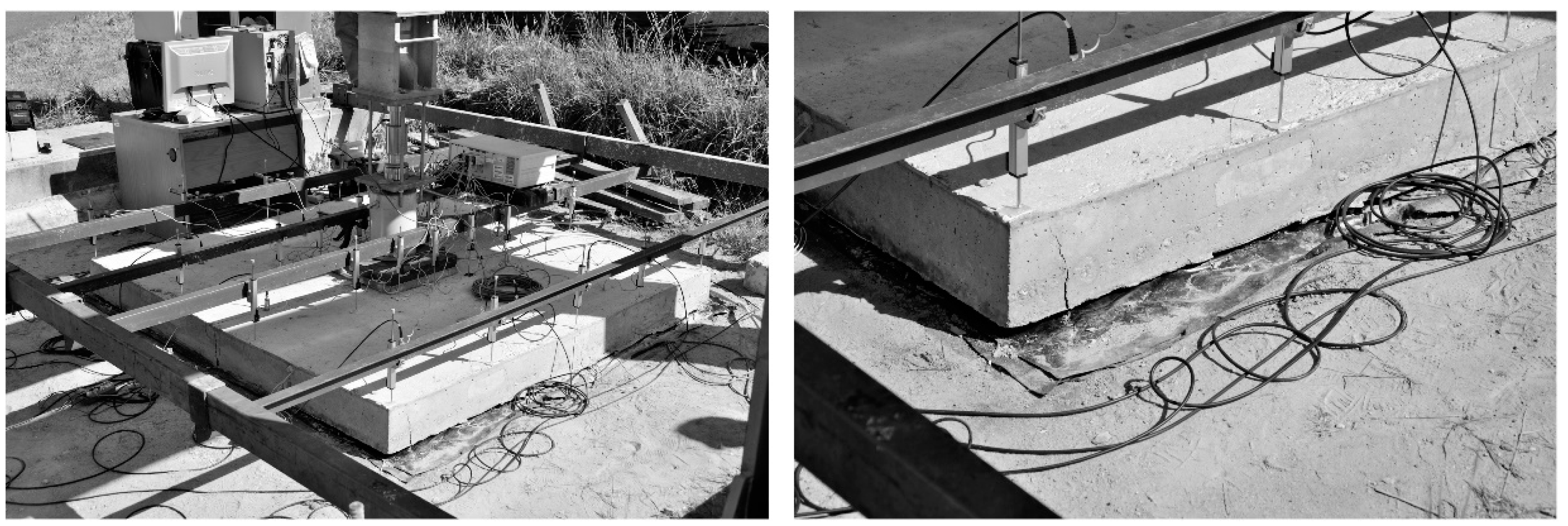
The slabs were loaded to the center by a gradual variable surcharge applied by a hydraulic press (Figure 2). Loading was performed using a special strutted steel structure (experimental stand), applied step-by-step at a uniform velocity until the slab failed (the partial loading step corresponded to 75 kN) [19]. The experimental measurements of slab settlement and vertical stresses in the subsoil below the slab were carried out during the loading process.
This paper did not examine the results of monitoring related to settlements and strain inside the slab, as they have already been presented in other studies [20,21,22]. Instead, the focus of this paper was on monitoring the vertical stresses in the subsoil below the slab. This was performed using nine GEOKON vibrating wire flat cells [23] located at three depth levels (marked X): (1) localization on contact surface (X = 1), (2) 0.35 m below the contact surface (X = 2), and (3) 0.8 m below the contact surface (X = 3). These are shown in Figure 3. In each of the three depth levels, three flat cells were located. One cell was placed in the center of the slab (Y = 1), the second cell was at the center of the edge of the slab (Y = 2), and the third cell was located at the corner (Y = 3). Flat cells located at the contact surface were marked 1.1, 1.2, and 1.3; cells at 0.35 m below the surface were marked 2.1, 2.2, and 2.3; and cells at 0.85 m below the surface were marked 3.1, 3.2, and 3.3.
4. Results of Experimental Works
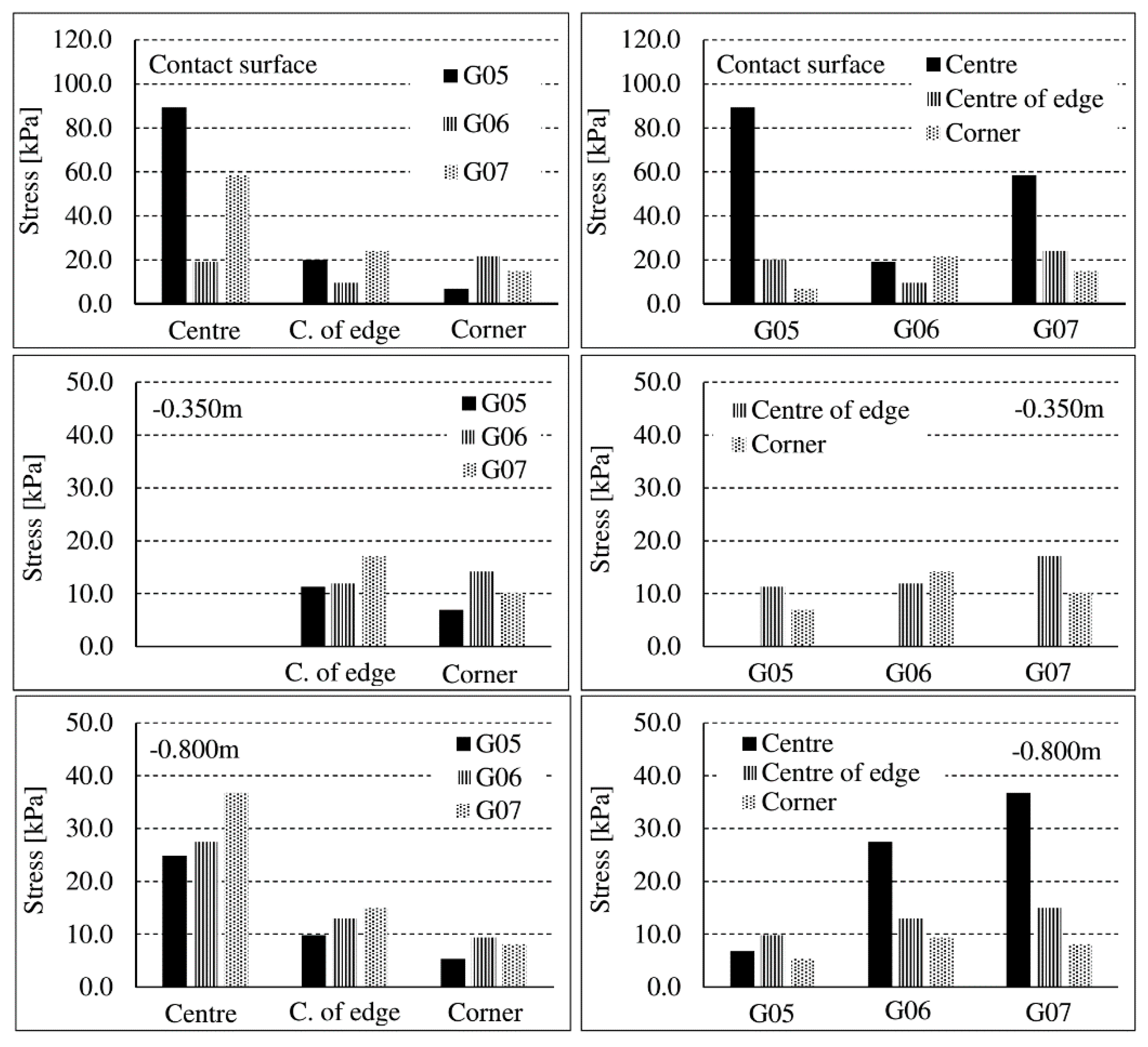
Figure 4 presents the total vertical stresses below the three variant slabs marked G05, G06, and G07. Evaluation was carried out under the assumption that the self-weight of the slab and original stress (soil weight above the measuring cell) are removed.
The first row in Figure 4 corresponds to stresses in two different depths below the center point of the slab (note that one sensor stopped working at the depth of 0.35 m, so only two depths were investigated and evaluated) for tested slabs G05, G06, and G07. The second row represents the stresses in three different depths below the center of the slab edge, while the third row illustrates the situation below the corner of the slab.
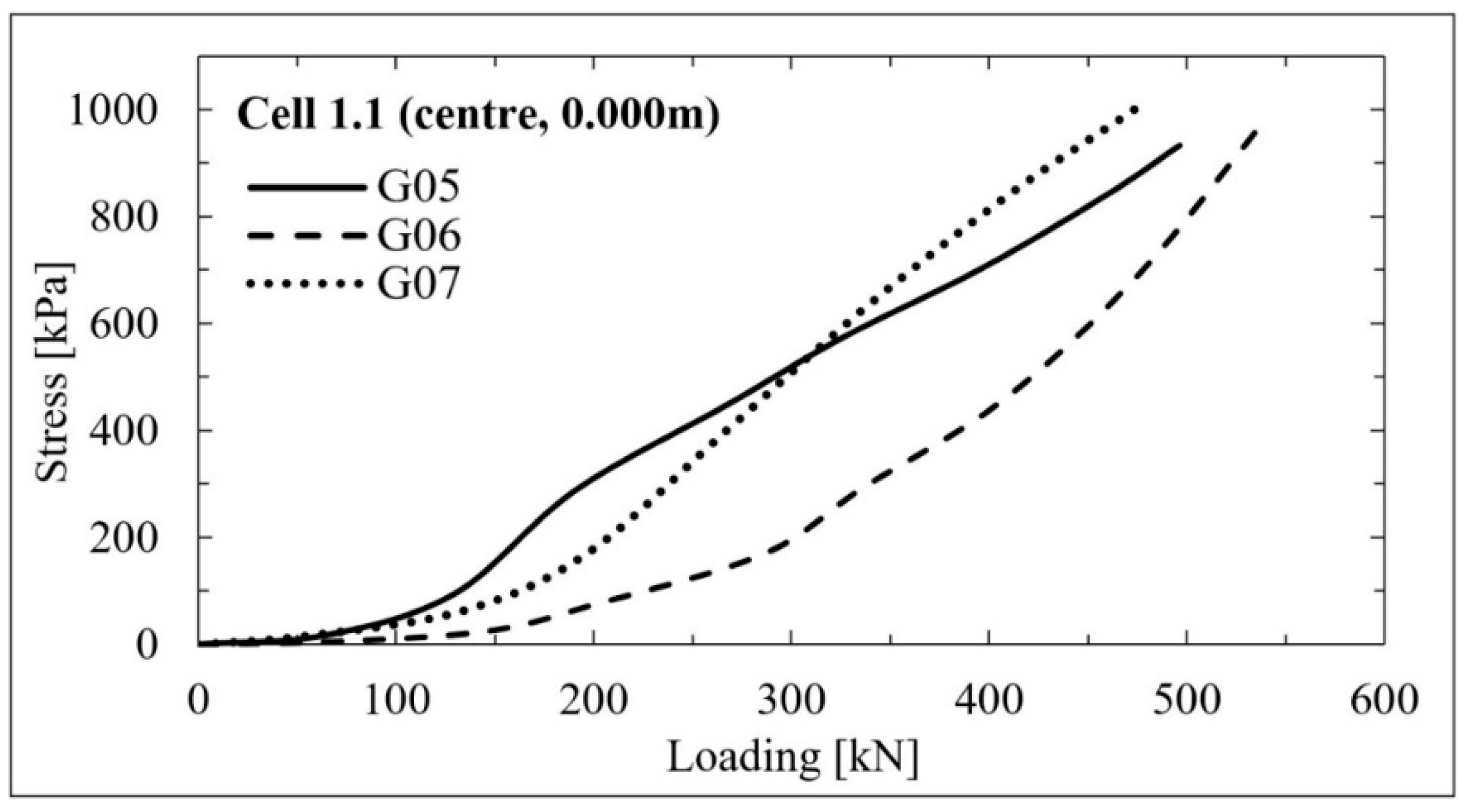
Results obtained from cell 1.1—the contact cell located below the center point of the slab—are presented in Figure 5. Contact stresses below the center of slab G05—the slab with the high relative stiffness—increased significantly until a loading of 180 kN was achieved. At a higher load, we registered a lower gradient of contact stresses at this monitoring point.
In the case of slab G06, the contact stress increased with the lower gradient at lower load level. When this load of 300 kN was exceeded, the gradient of the contact stresses continuously increased. Due to the softening of the subsoil from the increased moisture in the subsoil layer below slab G06 (higher moisture was induced by stronger rainfall before testing), the relative stiffness increased. Compared with other slabs, it is very important to note that relative stiffness of the foundation increased due to the expected (but not quantified) softening of the subsoil below slab G06 due to the significant precipitation prior to its testing. This impact was registered and documented (in accordance with the theory) by decreasing the contact measured stresses in the central zone below the slab G06 and increasing the contact stresses below the corner.
In the case of the G07 slab test, the increased gradient of the contact stress was evident mainly in the middle of the loading interval (200–300 kN). Outside of this loading interval, the gradient of contact stresses was lower.
Figure 6 shows a load–contact stress curve below the center of the slab edge. The results of the measurements document the reduction in the stresses at a specific load level resulting from a significant deflection of the slab observed during the test. This deflection led to an uplift of the edges and corners of the slab and a gap between the soil and slab opened in some parts of the contact surface (the contact surface was reduced).
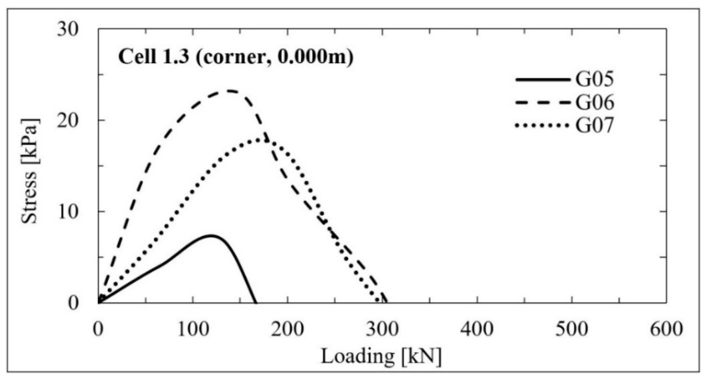
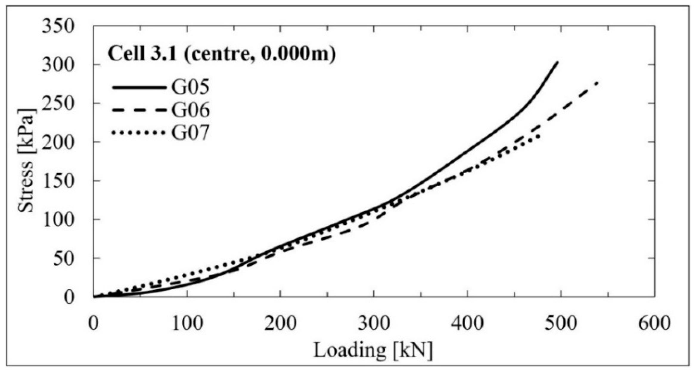
A more significant impact of the uplift of the slab corners is documented in Figure 7. The results presented in Figure 6 and Figure 7 show that a loss of contact between the slab and the subsoil at the slab corners occurred at a lower load compared to the load required to create a gap on the edge of the slab. The pressure cell located at the maximum investigated depth below the slab, i.e. at a depth of 0.8 m, did not record any significant differences in the values of the vertical total stresses under the slabs (Figure 8). Some minor differences were visible for the G05 slab, but they were observed for loads higher than 350 kN only.
The comparison of stresses below the three investigated slabs—G05, G06, and G07—related to the loading of 125 kN (before the slab uplift) is presented in Figure 9.
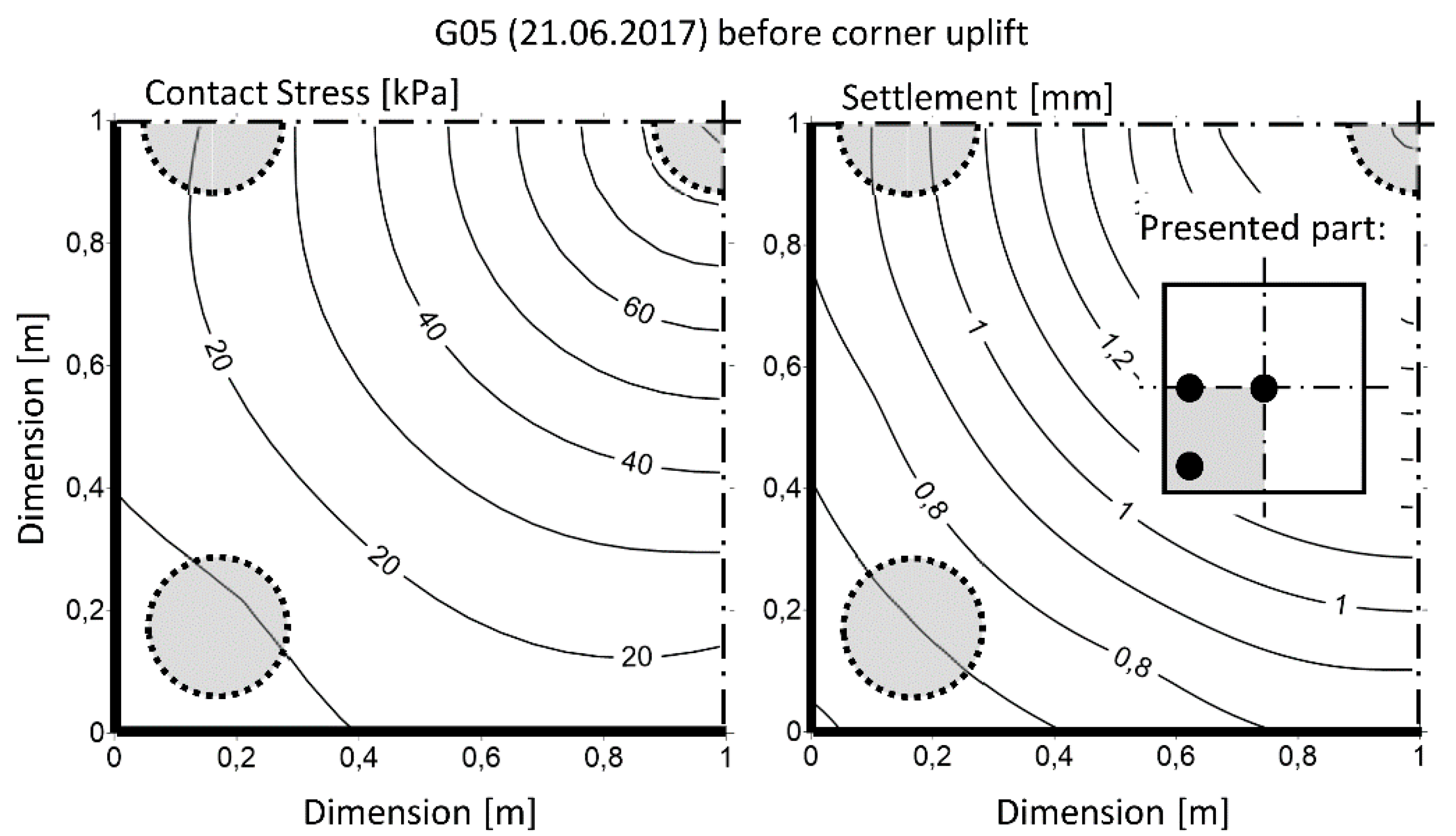
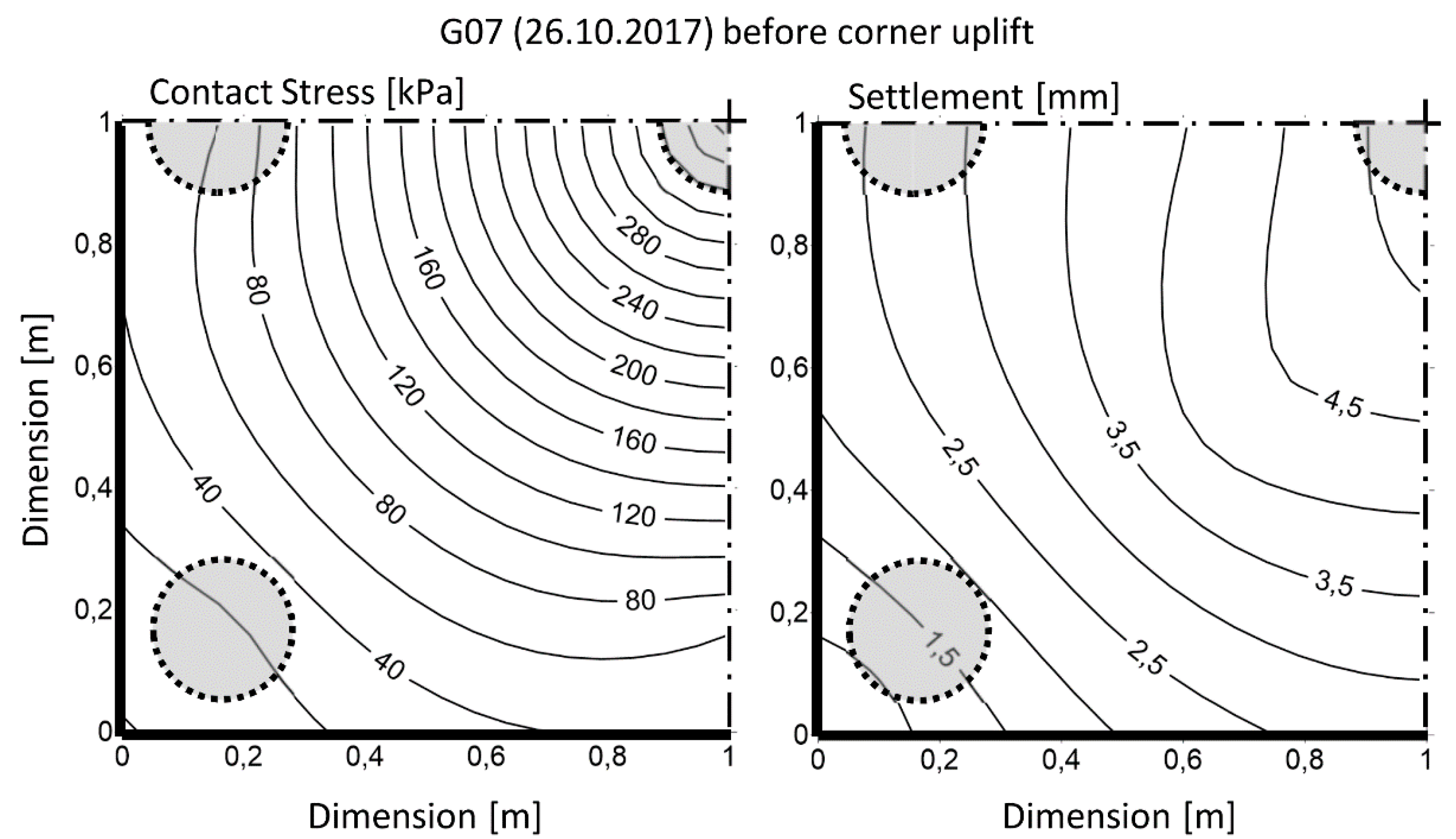
Figure 10, Figure 11, Figure 12 and Figure 13 show the relation between the settlements and contact stresses below the slabs G05 and G07, respectively. Figure 10 presents the situation without the uplift of G05 slab. Figure 11 shows the corner uplift occurrence, which was indicated by the flat cell located at the slab corner (the registered stress value was zero). Figure 12 and Figure 13 present the analogical evaluation for slab G07.
The experimental investigations of slab behavior during the test show that the amount of fibers influenced the increase in the bearing capacity of the slab. The bearing capacity corresponded to the loading at which significant compression failure of the slab was observed. The bearing capacity of slabs G05 (25 kg of fibers per m3), G06 (50 kg of fibers per m3), and G07 (75 kg of fibers per m3) corresponded to 478 kN, 550 kN, and 635 kN, respectively. This paper is primarily focused on the soil stress analysis below the slab, and additional detailed information relating to slab behavior during the mentioned experimental works have been explored in other papers [24,25,26].
5. Discussions and Results
Slab-subsoil interaction is a complex problem that depends on many factors, including the properties of the structure and the subsoil. This interaction has a significant rheological character as confirmed by the results. The relative stiffness of the foundation was not identical throughout the whole load cycle. Corresponding changes in stiffness were caused, among other factors, by changes in the subsoil below the slab (influence of soil moisture variation, etc.). The bearing capacity of slab increased with the amount of fibers considered within this study.
Experimental stress measurements indicated some decrease in the effective contact surface between the slab and the subsoil during loading due to the uplift of the corners and edges of the slab. The quantitative and qualitative character of uplift changed during the test depending on reinforcement of the slab and load size (assuming identical subsoil and identical dimension of tested slabs). The contact surface corresponding to slab G05 was reduced by 18% as a result of the corner uplift. For slab G07, the surface reduction was approximately 5%. (This comparison corresponds to the loading step in which the uplift initiation was observed). This phenomenon led to the sudden increase of stress gradient in all contact points inside the reduced contact area and also below it. This qualitative change in contact stress development was less remarkable for slabs with higher amount of fibers. The slab uplift was reflected by the manifestation of the more significant increase of tensile stresses inside some parts of the investigated slab, which resulted in crack initiation followed by their gradual expansion and interconnection.
The vertical contact stresses induced by the vertical axial load of the slab reached maximum values below its center, regardless of the slab variant. Lower contact stresses were reached below the edge of the slab, and the lowest stresses were monitored below the corner of the slab. However, it is important to note in this context that the mentioned uplift of the edges and corners of the slab was manifested during testing.
Different contact stresses were evident for the individual tested slabs, but it was not possible to clearly distinguish the effect of the different degree of reinforcement (among of fibers) on the one side and changes to the properties of the subsoil on the other side (the identical subsoil was assumed during testing, but the soil properties can change due to variations in climate conditions).
Some differences in vertical total stress were identified for specific slabs at a depth of 0.35 m below the contact surface. Due to the monitoring pressure cell located below, the center of the slab already showed a defect at the beginning of measurement and the values of vertical total stresses below the center could not be evaluated.
The performed measurements showed that up to the load of approximately 300–400 kN, the significant differences of the vertical stresses below the center of the edge of slabs G05 and G06 were not indicated. If this load limit exceeded, the vertical stresses below slabs G05 and G06 gradually dropped, probably due to the uplift of edges and corners of the slabs. A different situation occurred at this depth under slab G07. Below this slab, the stresses below the center of the edge increased with the increasing loading up to the maximal applied load. Unlike the situation below slabs G05 and G06, the monitoring did not detect a significant stress drop.
The influence of corner uplift corresponding to the specific loading was manifested at the depth of 0.35 m under the contact surface too. At this depth level, the vertical stress under the corner of slab G05, G06, and G07 dropped to a force of 150 kN, 180 kN, and 200 kN, respectively. The limit force value corresponding to the drop of vertical stress under the corner evaluation directly depended on the amount of fibers in slab. The maximal value of induced vertical stress at this depth achieved approximately 20 kPa, independent of the type of slab.
At a depth of 0.8 m—the maximum investigated depth—below the contact surface, the effect of the different contents of the fibers in the slab as well as the potential degradation of soil characteristic was already eliminated and registered stresses were practically identical.
Author Contributions
Conceptualization, E.H.; Data curation, M.M. and H.L.; Formal analysis, H.L., T.Q.B. and P.D.N.; Investigation, M.M.; Methodology, E.H.; Supervision, E.H.; Writing—original draft, E.H. and M.M.; Writing—review & editing, E.H. and M.M.
Funding
This research was funded by [Grantová agentura České republiky, grant number [16-08937S].
Acknowledgments
This paper was developed with the financial support of the project GACR No. 16-08937S “State of stress and strain of fiber reinforced composites in interaction with the soil environment”.
Conflicts of Interest
The authors declare no conflict of interest.
References
- Muller, H.S.; Haist, M.; Vogel, M. Assessment of the sustainability potential of concrete and concrete structures considering their environmental impact, performance and lifetime. Constr. Build. Mater. 2014, 67, 321–337. [Google Scholar] [CrossRef]
- Cement Technology Roadmap 2009, Carbon Emissions Reductions Up to 2050; International Energy Agency: Paris, France, 2009; Available online: https://www.iea.org/publications/freepublications/publication/Cement.pdf (accessed on 17 April 2018).
- Boswell, L.F.; Scott, C.R. A flexible circular plate on a heterogeneous elastic half-space influence coefficients for contact stress and settlement. Geotechnique 1975, 25, 604–610. [Google Scholar] [CrossRef]
- Myslivec, A.; Jesenak, J.; Eichler, J. Mechanika Zemin; SNTL: Praha, Czech Republic, 1970. [Google Scholar]
- Davis, E.H.; Poulos, H.G. The use of elastic theory for settlement prediction under three-dimensional conditions. Geotechnique 1968, 18, 67–91. [Google Scholar] [CrossRef]
- Balakrishna, C.K.; Murthy, B.R.S.; Nagaraj, T.S. Stress distribution beneath rigid circular foundations on sands. Int. J. Numer. Anal. Methods Geomech. 1992, 16, 65–72. [Google Scholar] [CrossRef]
- Delpak, R.; Rowlands, G.O.; Siraty, A. Modelling of strip foundations for serviceability assessment. Struct. Eng. Lond. 1992, 70, 412–420. [Google Scholar]
- Bose, S.K.; Das, S.C. Nonlinear finite element analysis of stresses and deformations beneath rigid footings. Comput. Struct. 1997, 62, 487–492. [Google Scholar] [CrossRef]
- Abdullah, W.S. New elastoplastic method for calculating the contact pressure distribution under rigid foundations. Jordan J. Civ. Eng. 2008, 2, 71–89. [Google Scholar]
- Yamin, M.M.; Ashteyat, A.M.; Al-Mohd, I.; Mahmoud, E. Numerical study of contact stresses under foundations resting on cohesionless soil: Effects of foundation rigidity and applied stress level KSCE. J. Civ. Eng. 2017, 21, 1107–1114. [Google Scholar] [CrossRef]
- Brown, P.T. Numerical analysis of uniformly loaded circular rafts on elastic layers of finite depth. Geotechnique 1969, 19, 301–306. [Google Scholar] [CrossRef]
- Garg, V.; Hora, M.S. A review on interaction behavior of structure-foundation-soil system. Int. J. Eng. Res. Appl. 2012, 2, 639–644. [Google Scholar]
- Selvadurai, A.P.S.; Rabbaa, S.A.A. Some experimental studies concerning the contact stresses beneath interfering rigid strip foundations resting on a granular stratum. Can. Geotech. J. 1983, 20, 406–415. [Google Scholar] [CrossRef]
- Smith-Pardo, J.P.; Bobet, A. Behavior of Rigid Footings on Gravel under Axial Load and Moment. J. Geotech. Geoenviron. Eng. 2007, 133, 1203–1215. [Google Scholar] [CrossRef]
- Alani, A.M.; Beckett, D. Mechanical properties of a large scale synthetic fibre reinforced concrete ground slab. Constr. Build. Mater. 2013, 41, 335–344. [Google Scholar] [CrossRef]
- Sucharda, O.; Bilek, V.; Smirakova, M.; Kubosek, J.; Cajka, R. Comparative evaluation of mechanical properties of fibre-reinforced concrete and approach to modelling of bearing capacity ground slab. Period. Polytech. Civ. Eng. 2017, 61, 972–986. [Google Scholar] [CrossRef]
- Stolarik, M.; Hrubesova, E.; Pinka, M. Dynamic response of the experimental foundation slab—Seismic measurement and analysis. Int. Multidiscip. Sci. GeoConf. Surv. Geol. Min. Ecol. Manag. SGEM 2015, 2, 261–268. [Google Scholar]
- Mohyla, M.; Vojtasik, K.; Stolarik, M.; Pinka, M.; Lahuta, H. Experimentally measurement and analysis of stress under foundation slab. Int. J. GEOMATE 2017, 13, 128–135. [Google Scholar] [CrossRef]
- Lahuta, H.; Hrubesova, E.; Duris, L.; Petrasova, T. Behaviour subsoil of slab foundation under loading. SGEM 2015, 2, 119–126. [Google Scholar]
- Cajka, R.; Burkovic, K.; Buchta, V. Foundation slab in interaction with subsoil. Adv. Mater. Res. 2014, 838–841, 375–380. [Google Scholar] [CrossRef]
- Mynarcik, P.; Cajka, R. Experimental testing of post-tensioned concrete industrial floor model—Subsidence analysis. Int. J. Mech. 2016, 10, 33–38. [Google Scholar]
- Cajka, R.; Labudkova, J.; Mynarcik, P. Numerical solution of soil—Foundation interaction and comparison of results with experimetal measurements. Int. J. GEOMATE 2016, 11, 2116–2122. [Google Scholar] [CrossRef]
- Mohyla, M.; Vojtasik, K.; Hrubesova, E.; Stolarik, M.; Pinka, M. The optimalization of pressure cell installation via numerical simulation International. Int. Multidiscip. Sci. GeoConf. Surv. Geol. Min. Ecol. Manag. SGEM 2016, 1029–1036. [Google Scholar] [CrossRef]
- Mynarcik, P.; Labudkova, J.; Koktan, J. Experimental and numerical analysis of interaction between subsoil and post-ensioned slab-on-ground. J. Teknol. 2016, 23–27. [Google Scholar] [CrossRef]
- Hrubesova, E.; Lahuta, H.; Duris, L.; Jaafar, M. Mathematical modeling of foundation-subsoil interaction. SGEM 2015, 2, 437–444. [Google Scholar]
- Sucharda, O.; Smirakova, M.; Vaskova, J.; Mateckova, P.; Kubosek, J.; Cajka, R. Punching Shear Failure of Concrete Ground Supported Slab. Int. J. Concr. Struct. Mater. 2017. [Google Scholar] [CrossRef]
Figure 1.
Various shapes of contact stresses under a rigid foundation.

Figure 2.
Scheme of experimental measurements on the stand.

Figure 3.
Localization of flat cells in experiment (in plan and cross section).

Figure 4.
Assessment of monitored stresses below slabs G05, G06, and G07.

Figure 5.
Load–contact stress curve below the center of slab.

Figure 6.
Load–contact stress curve below the center of the slab edge.

Figure 7.
Load–contact stress curve below the corner of slab.

Figure 8.
Load–stress curve below the center of slab (at a depth 0.8 m).

Figure 9.
Comparison of stresses below slabs G05, G06, and G07 with a slab loading of 125 kN.

Figure 10.
Contact stresses distribution below the G05 slab (left) and corresponding settlement of G05 slab (right) before the corner uplift occurrence. Flat cells are noted by circular marks.
Figure 10.
Contact stresses distribution below the G05 slab (left) and corresponding settlement of G05 slab (right) before the corner uplift occurrence. Flat cells are noted by circular marks.

Figure 11.
Contact stresses distribution below the G05 slab (left) and corresponding settlement of G05 slab (right) after the corner uplift occurrence. Flat cells are noted by circular marks.
Figure 11.
Contact stresses distribution below the G05 slab (left) and corresponding settlement of G05 slab (right) after the corner uplift occurrence. Flat cells are noted by circular marks.

Figure 12.
Contact stresses distribution below the G07 slab (left) and corresponding settlement of G07 slab (right) before the corner uplift. Flat cells are noted by circular marks.
Figure 12.
Contact stresses distribution below the G07 slab (left) and corresponding settlement of G07 slab (right) before the corner uplift. Flat cells are noted by circular marks.

Figure 13.
Contact stresses distribution below the G07 slab (left) and corresponding settlement of G07 slab (right) after the corner uplift occurrence. Flat cells are noted by circular marks.
Figure 13.
Contact stresses distribution below the G07 slab (left) and corresponding settlement of G07 slab (right) after the corner uplift occurrence. Flat cells are noted by circular marks.


Table 1.
Material parameters of quasi-homogenized subsoil under tested foundation.
| Slab | Cement | Water | Fine Aggregate * | Coarse Aggregate ** | Content of Fibers | Admixtures (Stacheplast) *** |
|---|---|---|---|---|---|---|
| G05 | 310 | 195 | 920 | 970 | 25 | 3 |
| G06 | 310 | 195 | 920 | 970 | 50 | 3 |
| G07 | 320 | 200 | 945 | 970 | 75 | 3.2 |
Notes: * mining aggregate; ** mining aggregate (maximum aggregate size of 16 mm); *** lignosulfonate plasticizer (STACHEMA CZ company).
Table 2.
Characteristics of tested slabs labeled G05, G06, and G07.
| Slab Label | Precipitation [mm] | Date of the Test | Content of Fibers kg/m3 | Compressive Strength [MPa] (Cylindrical Samples—An Average of 3 Tests) | Compressive Strength [MPa] (Cubic Samples—An Average of 6 Tests) | Young’s Module of Elasticity [GPa] (Cylindrical Samples—An Average of 3 Tests) | Relative Stiffness (Schultz) |
|---|---|---|---|---|---|---|---|
| G05 | 23 | 21.6.2017 | 25 | 24.86 | 30.9 | 19.7 | 0.644 |
| G06 | 44 | 18.9.2017 | 50 | 22.1 | 24.4 | 18.5 | 0.605 |
| G07 | 17 | 26.10.2017 | 75 | 23.6 | 28.2 | 18.3 | 0.598 |
Table 3.
Characteristics of tested slabs labeled G05, G06, and G07.
| Slab | Cement | Water | Fine Aggregate * | Coarse Aggregate ** | Content of Fibers | Admixtures (Stacheplast) *** |
|---|---|---|---|---|---|---|
| G05 | 310 | 195 | 920 | 970 | 25 | 3 |
| G06 | 310 | 195 | 920 | 970 | 50 | 3 |
| G07 | 320 | 200 | 945 | 970 | 75 | 3.2 |
Notes: * mining aggregate; ** mining aggregate (maximum aggregate size of 16 mm); *** lignosulfonate plasticizer (STACHEMA CZ company).
© 2018 by the authors. Licensee MDPI, Basel, Switzerland. This article is an open access article distributed under the terms and conditions of the Creative Commons Attribution (CC BY) license (http://creativecommons.org/licenses/by/4.0/).
Share and Cite
MDPI and ACS Style
Hrubesova, E.; Mohyla, M.; Lahuta, H.; Bui, T.Q.; Nguyen, P.D. Experimental Analysis of Stresses in Subsoil below a Rectangular Fiber Concrete Slab †. Sustainability 2018, 10, 2216. https://doi.org/10.3390/su10072216
AMA Style
Hrubesova E, Mohyla M, Lahuta H, Bui TQ, Nguyen PD. Experimental Analysis of Stresses in Subsoil below a Rectangular Fiber Concrete Slab †. Sustainability. 2018; 10(7):2216. https://doi.org/10.3390/su10072216
Chicago/Turabian StyleHrubesova, Eva, Marek Mohyla, Hynek Lahuta, Tuan Quang Bui, and Phi Dinh Nguyen. 2018. "Experimental Analysis of Stresses in Subsoil below a Rectangular Fiber Concrete Slab †" Sustainability 10, no. 7: 2216. https://doi.org/10.3390/su10072216
Note that from the first issue of 2016, this journal uses article numbers instead of page numbers. See further details here.