Vibration Suppression of a Single-Cylinder Engine by Means of Multi-objective Evolutionary Optimisation


1
Department of Aeronautical Engineering and Commercial Pilot, International Academy of Aviation Industry, King Mongkut’s Institute of Technology Ladkrabang, Bangkok 10520, Thailand
2
Sustainable and Infrastructure Development Center, Department of Mechanical Engineering, Faculty of Engineering, KhonKaen University, KhonKaen City 40002, Thailand
*
Author to whom correspondence should be addressed.
Sustainability 2018, 10(6), 2067; https://doi.org/10.3390/su10062067
Submission received: 31 May 2018
/
Revised: 15 June 2018
/
Accepted: 15 June 2018
/
Published: 18 June 2018
(This article belongs to the Special Issue Multi-Objective and Multi-Attribute Optimisation for Sustainable Development Decision Aiding)
Abstract
:This paper presents a new design strategy for the passive vibration suppression of a single-cylindrical engine (SCE) through multi-objective evolutionary optimisation. The vibration causes machine damages and human pain, which are unsustainable problemsthat need to be alleviated. Mathematical forced vibration analyses of a single-cylinder engine, including dynamic pressure force due to ignition combustion, are presented. A multi-objective design problem is set to find the shape and size variables of the crank and connecting rod of the engine. The objective functions consist of the minimisation of the crank and connecting rod mass, and the minimisation of vibration response while the SCE is subject to inertial force and pressure force. Moreover, design constraints include crank and rod safety. The design problem is tackled by using an adaptation of a hybrid of multi-objective population-based incremental learning and differential evolution (RPBIL-DE). The optimum results found that the proposed design strategy is a powerful tool for the vibration suppression of SCE.
1. Introduction
A single-cylinder engine (SCE) is one of the most widely used engines, especially in motorcycles, which are the most popular two-wheel automotive in this world. It is also included in a variety of applications particularly for agricultural proposes such as the driving pump, walking tractor, lawnmower, etc. In contrast with the applications, the vibration of this engine is the main problem at present. Two causes of vibration are from moving links in a crank–slider mechanism and ignition pressure due to combustion process. These can be a cause of machine damages, human discomfort, and user-accumulated fatigue and pain. SCE vibration can be alleviated in two ways i.e., balancing and isolation.
Balancing a SCE can be classified as active and passive balancing [1]. Active balancing is a method for reducing shaking force and moment by introducing dummy pistons and geared revolving counter weights, etc. Passive balancing, on the other hand, is a method used to reduce shaking force and moment by the addition or removal of mass from various portions of the moving links.
Research work toward this area has been continually made. Lowen et al. [2] summarised the techniques for the force and moment balancing of linkages. Zhang and Chen [3] have applied vibration suppression of a four-bar linkage by using the weighted sum method, which is a means to convert multi-objective optimisation to become a problem with one design objective. The counterweights’ mass parameters were set as design variables in this passive balancing. Snyman et al. [4] have applied an unconstrained optimisation problem to minimise the transmission of engine vibration due to inertial forces to the supporting structure where the case study is a mounted four-cylinder V-engine rotating at idling speed by an active balancing method. The individual balancing masses and associated phase angles of counter rotating balancing masses were chosen as design variables. Chiou et al. [5] proposed an optimum design in which disk counterweights were added to reduce shaking force and moment of the drag-link drive of mechanical presses. Sleesongsom [6] proposed applying multi-objective optimisation to reduce the engine mount translation and rotation displacements of SCE where the normalised normal constraint method [7], in combination with sequential quadratic programming, is an optimiser. The use of finite element analysis and optimisation codes for connecting rod [8], crankshaft [9], and piston design [10] has been conducted. In addition, the finite element technique has been used to optimise the crankshaft parameters of a single-cylinder motorcycle engine to reduce vibration without considering the gas pressure force inside the combustion chamber [11].
The second vibration suppression technique for the engine is vibration isolation. The challenge for designers and engineers is how to properly select vibration isolators in order to minimise the force transmission to the engine base [11,12,13] and the powertrain mounting system [14,15]. Further work focuses on optimisation of engine mounting systems and blocks can be found in References [16,17,18,19,20,21,22,23], while the literature of using meta-heuristic algorithms (MHs) or evolutionary algorithms (EAs) for engine mounting and engine part design can be seen further in Reference [24].
Both methods has been studied and used in industry, but the new design technique still lacks development. Recent works of automotive technology have focused on designing the motor of an electric vehicle (EV) to increase its efficiency and reduce vibration [25]. This kind of automotive uses an electric motor as a power or hybrid with the traditional engine. This research focuses on optimising the flux-weakening performance and reducing the vibration of an Interior permanent magnet (IPM) motor for EVs using the evolutionary algorithm (EA), which focuses on the source of vibration similar to our present research. Furthermore, this kind of designing problem is multi-objective optimisation, but the authors compromise it to be a single objective. So, in the present research, we focus on using a multi-objective evolutionary algorithm (MOEA) to alleviate the vibration of a single-cylinder engine.
This research proposes a new design strategy for the vibration suppression of a single-cylinder engine using a multi-objective evolutionary algorithm (MOEA). In this design, design variables including the shape and sizing parameters of the engine are proposed to suppress the inertia force and pressure force, which are the main vibration causes of this kind of engine. The MOEA optimiser is the hybrid of multi-objective population-based incremental learning and differential evolution (RPBIL-DE). The new design technique can reduce the vibrations that cause machine damages, human discomfort, and user-accumulated fatigue and pain, which can lead to sustainable development.
2. Single-Cylinder Engine Model
Herein, vibration analysis of a single-cylinder engine system is simplified for ease in the computation of an optimisation process. The kinematic and dynamic force analyses of a crank–slider with external ignition forces are carried out, while the obtained reactions will be used as external forces for the engine box and mounting system.
2.1. Kinematic and Kinetic Analyses
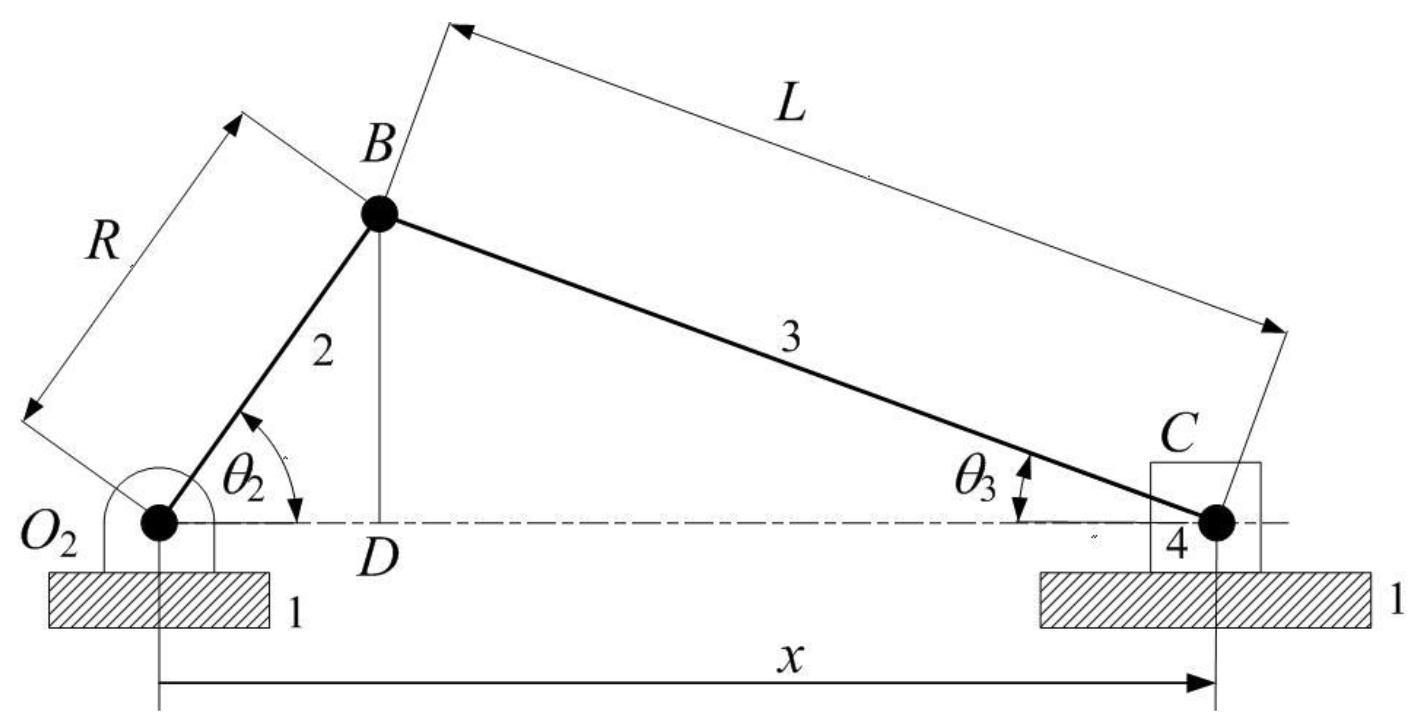
Figure 1 shows a crank–slider with the crank radius R and connecting rod L. The parameters θ2 and θ3 are the angular positions of links 2 and 3, respectively, while x is the position vector of the piston. Given that θ2, , and are known input variables, we can have the relation:
Having determined the first and second-order derivatives of Equation (1) with respect to time t and rearranged the derivative equations, the parameters and can be obtained as:
The position of the piston can be written as:
The velocity and acceleration of the piston can then be determined by differentiating Equation (3):
For the kinematic analysis of a crank–slider, if we have the input values of θ2, , and , the angular position, velocity, and acceleration of link 3, as well as the position, velocity, and acceleration of piston 4, can be computed using Equations (1)–(4).
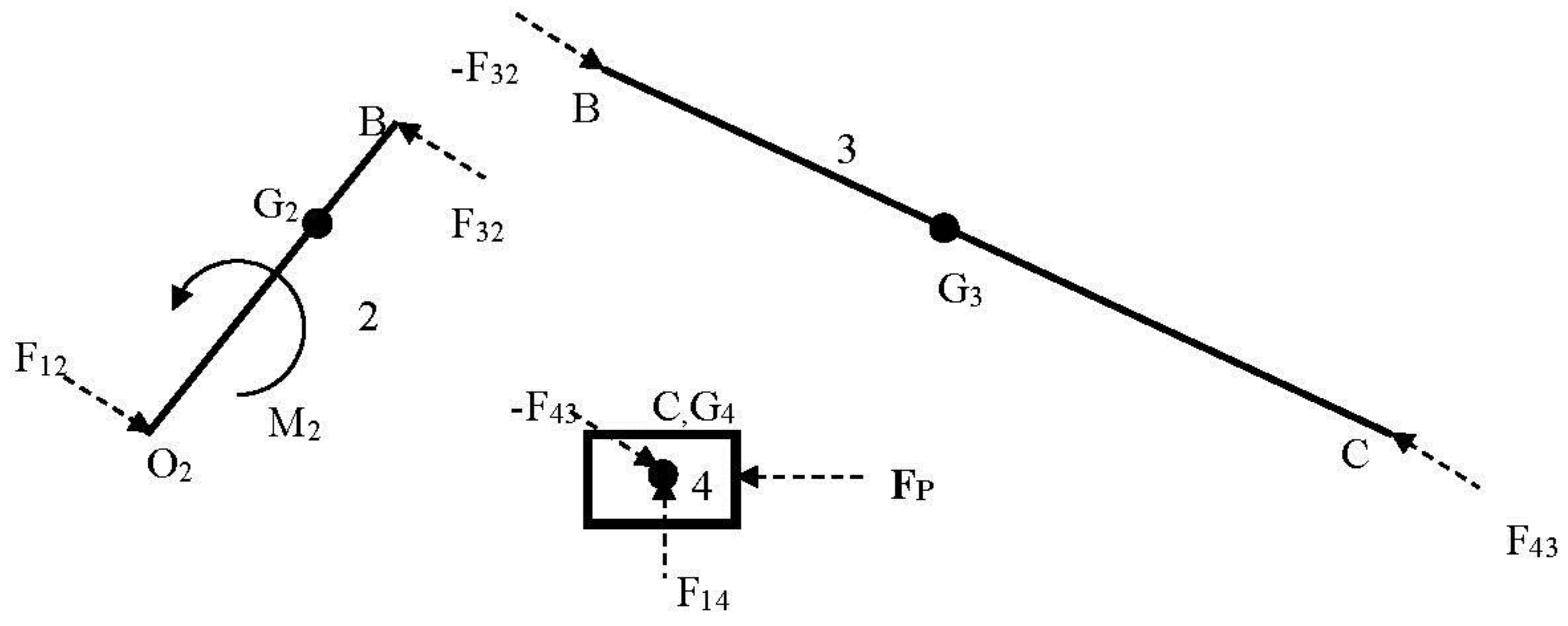
For dynamic force analysis in this paper, the crank–slider system is thought of as being kinematically driven by input angular velocity and acceleration at the input link 2. The kinematic analysis can be accomplished as previously detailed. A free-body diagram of a crank–slider at a particular motion phase is shown in Figure 2. The piston is subject to external forces due to gas pressure P, while the moment M2 is applied at link 2, so as to meet its prescribed motion. The force analysis can be computed using the following system of equations:
Where:
and: .
[A]{F} = {RHS}
F = {F12,xF12,yF32,xF32,yF43,xF43,yF14,yM2}T
Fij is the constrained force acting at body i by body j, mi is the mass of body i, IGi is the moment of inertia with respect to the axis at the centroid of body i, ri/j is the relative position vector of point i with respect to point j, and aC and aG2 are the acceleration vector of link 4 (piston) and the centre of gravity i in the x–y coordinates, respectively. The gas pressure P (kPa) in one cycle for some engine has been proposed by Asadi et al. [8] as follows:
Where x in above equation is in Equation (3).
The external force FP due to gas pressure can be computed by:
Where Patm is atmosphere pressure (kPa) and Ap is the piston area (m2).
FP = (P − Patm)Ap
2.2. Engine Vibration System
A mounted engine system will be modeled as a simple spring-mass system with the rigid mass having six degrees of freedom. Linear spring behavior is assumed as shown in Figure 3, while force and displacement relation can be written as:
Where k is spring stiffness, r0 is the position of the unstretched spring, r is the position vector of the spring under the force F, and δr is a spring translational vector.
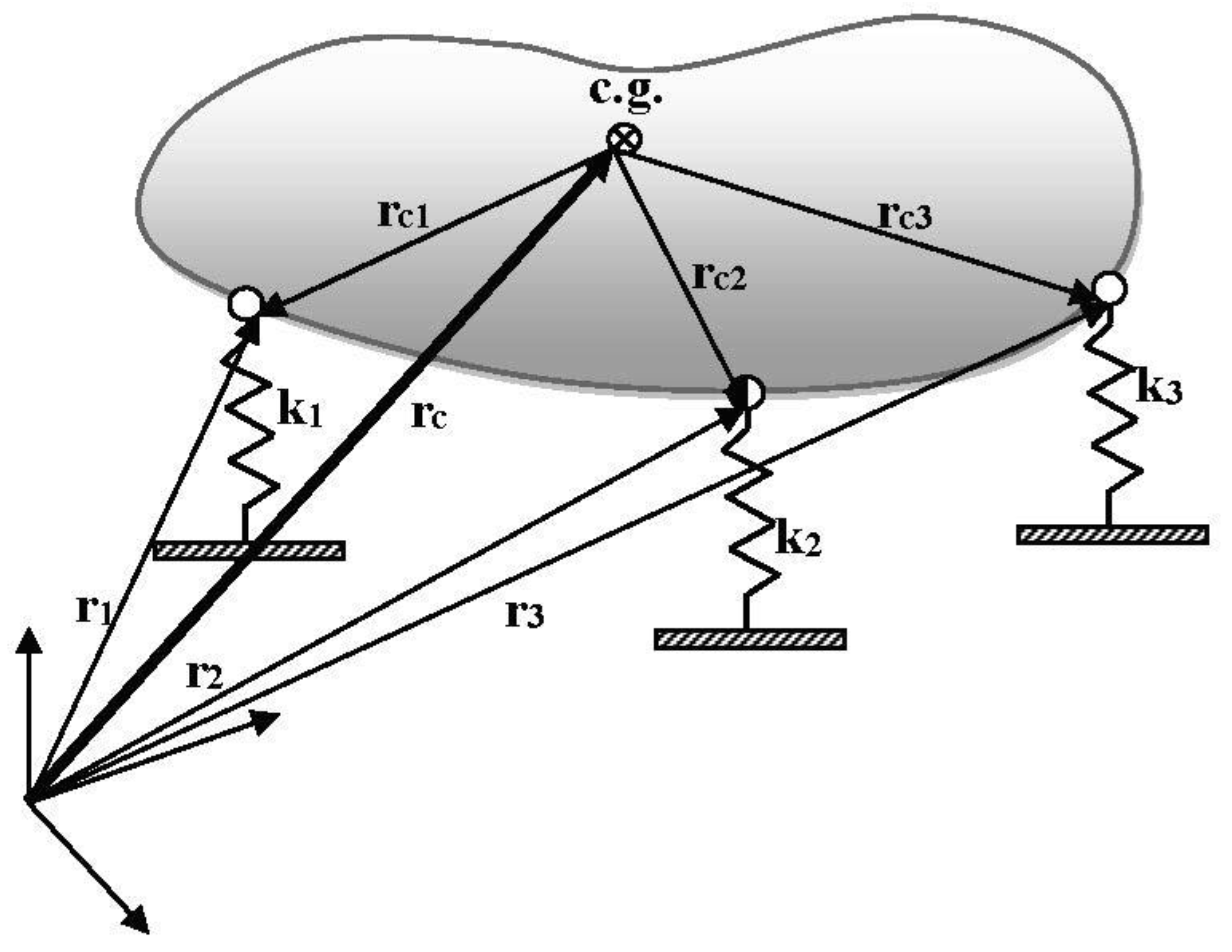
A rigid body attached with a number of linear springs is given in Figure 4. From the figure, the position vector of the i-th spring can be expressed with respect to the centroid position as:
Where ri is the position vector of spring I, rc is the position vector of the mass centre, and rci is the potion vector of spring i with respect to the centroid.
When the body is in motion, the derivation of the vectors in Equation (9) can be written as:
As the centroid and the i-th point are at the same body, we can have:
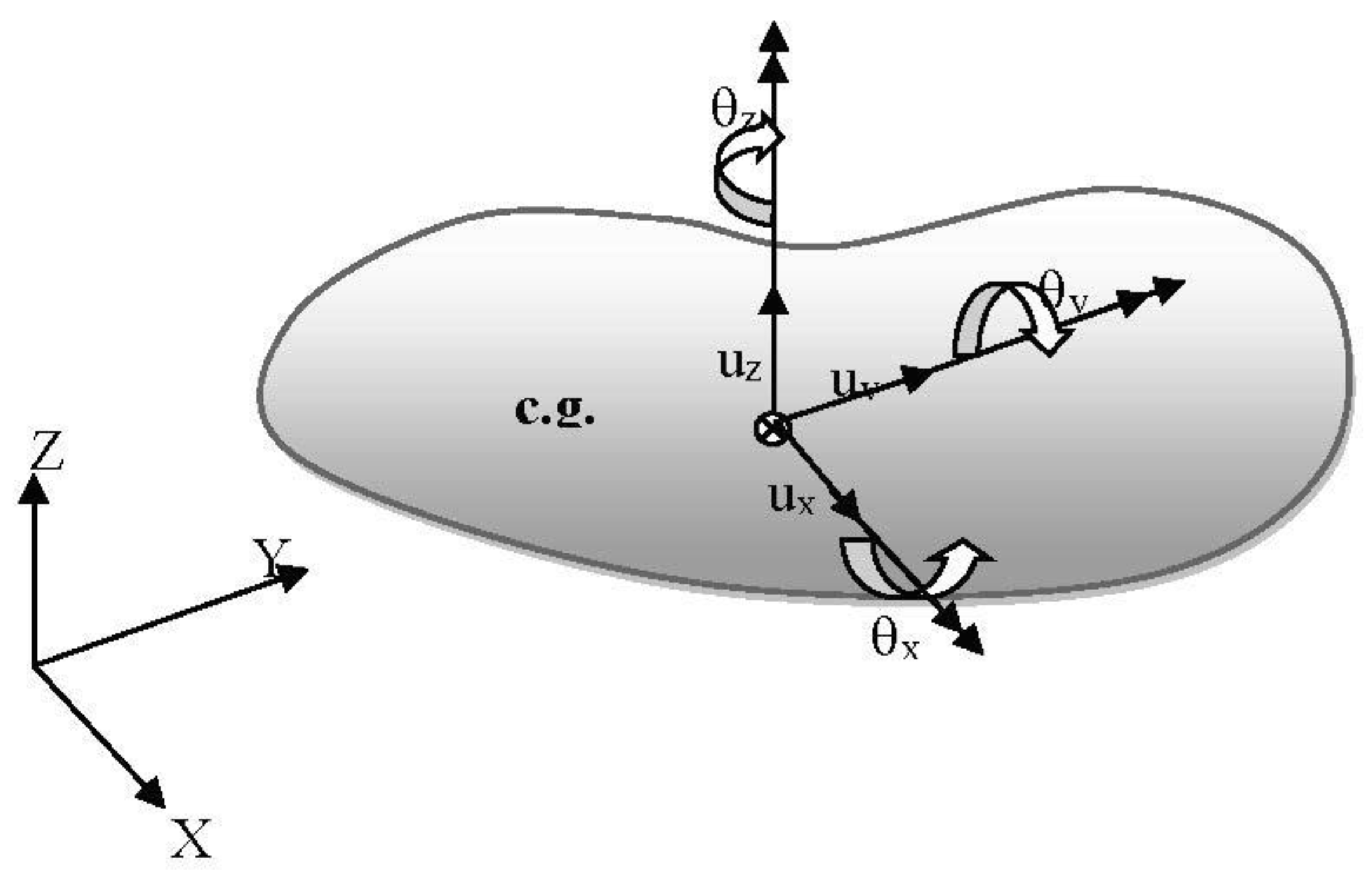
Where δθ is the vector of rotation displacements of the body. The translation and rotation vectors can be defined as:
Where ui is the translation in i-th direction and θi is the angular displacement in the i-th axis. The rigid body has six degrees of freedom, as shown in Figure 5. By substituting Equation (12) into Equation (11), we have:
Where Ti is called a transformation matrix for the i-th spring and d is the displacement vector of the body. As a result, elastic potential energy of the i-th spring is:
If the spring-mass system has n linear springs, the total elastic potential energy can be computed as:
Where K is the stiffness matrix of the system. The kinetic energy or the work due to inertial forces can be computed as:
Where:
m is body mass, and I is the matrix of moments of inertia. Adding the work done by external forces to the system, a vibration model of a three-dimensional (3D) spring-mass system can be expressed as:
Damping can be added to the model using a proportional damping matrix or a Reylize damping i.e.,
Where α and β are the proportional damping constants to be specified. The dynamic model then becomes:
C = αM + βK
In this work, numerical solutions of the system of differential equations in Equation (20) can be carried out by using Newmark’s integration technique [26].
3. Hybrid RPBIL-DE for Multi-Objective Optimisation
The multi-objective design problems of trusses [27,28] and mechanisms [29,30] have been solved with the hybridisation of real-code population-based incremental learning and differential evolution (RPBIL-DE). This optimizer is found to be one of the high-performance multi-objective optimisers, and is therefore selected to solve our problem in this study. The algorithm is extended from References [31,32] by integrating into it the differential evolution (DE) operators in the main procedure of real-code population-based incremental learning (RPBIL), leading to a hybrid algorithm [27]. This technique is developed to avoid a premature convergence searching of RPBIL due to the probability of matrix updating relying on the current best solution. The mutation and crossover of DE are incorporated into a RPBIL procedure. This hybridisation has been proved that it can increase the population diversity for multi-objective optimisation. Additionally, the non-dominated solutions can be chosen using a clustering technique that is detailed in Reference [33]. The RPBIL-DE and DE operator partsare shown in Algorithm 1, where F is a scaling factor, pc is a crossover probability, and CR is the probability of selecting an element of an offspring c in binomial crossover.
| Algorithm 1. Multi-objective RPBIL-DE [27]. |
| Input: NG(number of generation), NP (population size), nI(number of subinterval), NT(number of trays), objective function name (fun), Pareto archive size (NA) Output: xbest, fbest Initialisation: Pij= 1/nI for each tray, where Pij is a probability matrix Main steps : Generate a real-code population X from the probability trays and find f = fun(X) : Find a Pareto archive A 1: For i = 1 to NG 2: Separate the non-dominated solutions into NT groups using a clustering technique, and find the centroid rG of each group 3: Update each tray Pij based on rG 4: Generate a real-code population X from the probability trays 5: For j = 1 to NP recombine X and A using DE operators 5.1: Select p from A randomly 5.2: Select q and r from X randomly, q ≠ r 5.3: Calculate c = p + F(q −r) (DE/best/1/bin) 5.4: Set ci into its bound constraints. 5.5: If rand <pc, perform crossover 5.5.1: For k = 1 to n 5.5.2: If rand <CR, yk = ck 5.5.3: Otherwise, yj,k = pk 5.5.4: End 6: End 7: New real-code population is Y = {y1, …, yj, …, yNP} and find f = fun(Y) 8: Find non-dominated solutions from Y∪A and replace the members in A with these solutions 9: If the number of archive members is larger than NA, remove some of the members using a clustering technique 10: End |
For more details of RPBIL-DE, see Reference [27].
4. Design Problems
A simplified forced vibration model is used in this study instead of the more complicated model as presented in Reference [34]. Figure 6 displays the vibration model of a mounted single-cylinder engine where the mass matrix (including mass and moments of inertia) and the mass centre of the engine system are set to be constant. The engine box is attached to the ground by using four liner springs as shown. The origin of the reference rectangular coordinates is located at the engine box mass centre. For a computational procedure, forces and moments due to the moving links of a crank–slider are computed separately. Then, the dynamic force vector is obtained as:
Where .
The parameters according to the kinematic, force, and vibration analyses are given in Table 1. The external force due to pressure inside the cylinder followed Equation (6). The fidelity of the optimisation result in the next section is affected by the pressure force and inertia force, which will be studied in the next section. International System of Units (SI) are used unless otherwise specified. Figure 7 displays the top and front views of the crank. The parameters used to define the crank dimensions and shape are tC, lP, RC1, RC2, R2, rC, and ψ. If the values of those parameters are known, the mass centre and moment of inertia of the crank can be calculated. Figure 8 shows the connecting rod where nine design parameters are used to define the shape and dimensions of the rod as l1, l2, b1, b2, R1, R2, t, rp1, and rp2. It should be noted that the crank and rod are created for design demonstration in this paper. For practical applications, their shapes may be defined differently. From Figure 7 and Figure 8, lP = l1, and R2 = RC2, so 14 parameters are assigned as elements of a design vector as x = {RC1, RC2, rC, R2, ψ, lP, tC, R1, rp1, rp2, l2, t, b1, and b2}T.
The multi-objective design problem for this work is posed to find a design variable vector x such that:
Min: f = {f1(x),f2(x)}T
Subject to:
Where σCrank is the maximum stress on the crank, σall is an allowable stress, and σRod is the maximum stress on the connecting rod. The bound constraints are set as xl = {0.03, 0.05, 0.015, 0.01, π/6, 0.03, 0.01, 0.03, 0.02, 0.01, 0.02, 0.002, 0.02, and 0.01}T, and xu = {0.045, 0.09, 0.04, 0.03, π, 0.05, 0.03, 0.05, 0.03, 0.03, 0.04, 0.005, 0.04, and 0.03}T. The buckling factor for the rod λRod is defined as the ratio of critical load to applied load. The first three design constraints are set for structural safety, while the other constraints are assigned for manufacturing tolerances and practicality. The objective functions used in this study are set as f = {urms + θrms, mass}T. The root mean squares (RMS) of the vibration translations (urms) and rotations (θrms) over the period t∈ [0, tmax] can be computed as:
and:
σCrank ≤ σall
σRod ≤ σall
λRod ≥ 1
rp1 ≥ rp2 + 0.005 m
l2 ≥ b1 + 0.005 m
b1 ≥ b2 + 0.02 m
rp1 ≥ rp2 + 0.005 m
l1 ≥ l2
R1 ≥ rp1 + 0.002 m
rC1 ≥ R2 + 0.002 m
RC1 ≥ rc1 + 0.002 m
R1 ≥ R2 + 0.002 m
xl≤ x ≤ xu
In the function evaluation process, with the given input design vector x being decoded, the shape and sizing parameters are repaired to meet constraints 4–12, and the inertial properties of the crank and rod can then be computed (the rest of constraints will be handled by using the non-dominated sorting scheme [35]. Then kinematic and dynamic force analyses are carried out as detailed in Section 2. A simple finite element model using a three-dimensional (3D) beam element is applied to determine the maximum stresses on the crank and rod. A buckling factor is also calculated in the cases of the rod. Also, the obtained dynamic forces are used as external excitation for the vibration model of the engine. Having obtained a dynamic response, the objective functions can then be computed.
Three multi-objective optimisation problems with the same design objectives and constraints but different engine rotational speeds are posed as:
- OPT1: min {urms + θrms, mass}, constant crank angular speed 1000 rpm
- OPT2: min {urms + θrms, mass}, constant crank angular speed 1500 rpm
- OPT3: min {urms + θrms, mass}, constant crank angular speed 2000 rpm
The RPBIL-DE is used to tackle each design problem, with 10 runs starting with the same initial population. The population size is set to be 100, while the total number of iterations is 150. The crank and connecting rod are made of alloy steel AISI 4140H with a Young’s modulus of 211.65 GPa, σyt = 417.1 MPa, and density of 7850 kg/m3. For each finite element analysis, the maximum compressive force over the period of time [0, tmax] will be used for buckling calculation.
5. Pressure Force and Inertia Force Validation
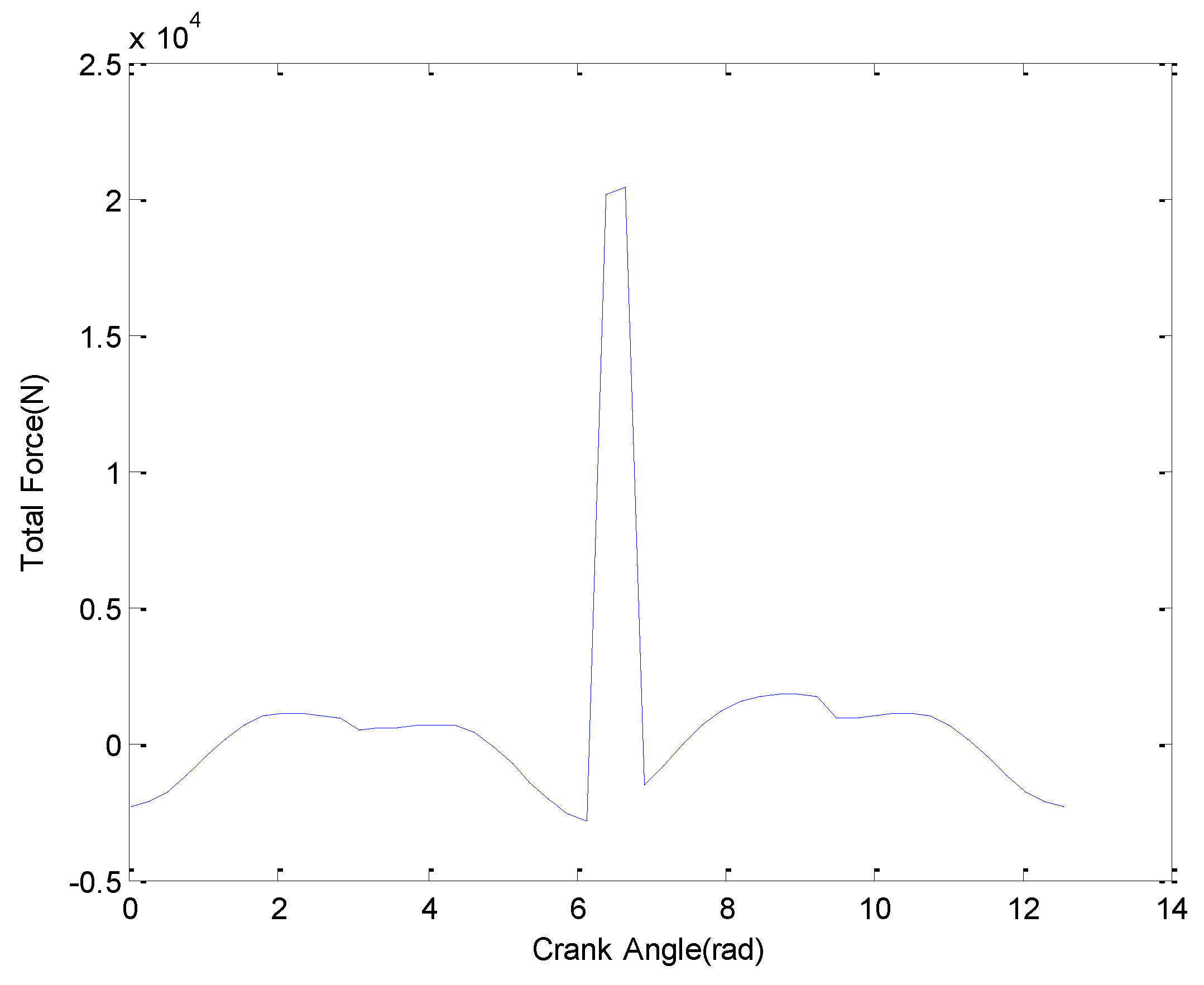
The gas pressure force and inertia force exert on the engine box similar to an external force. The fidelity of the both forces is very important in the vibration analysis of the single-cylinder engine, which we will do by considering the forces versus the crank angle. The gas pressure force, inertia force, and total force in one cycle is coded by using MATLAB commercial software over the interval [0, tmax], as shown in Figure 9, Figure 10 and Figure 11 at 1000 rpm. The maximum gas pressure force exerted on the piston head occurred at the maximum torque, but the maximum tensile force occurred during the maximum revolution speed [8]. Figure 9 shows that the maximum gas pressure force is 22,374 N, which occurs in the combustion process. The inertial force due to the slider–crank mechanism in the x direction is show in Figure 10; meanwhile, the maximum inertia in positive direction is 1141N, while the negative inertia force is 2286 N. Figure 11 shows the total force due to the gas pressure force and inertia force that give the maximum gas pressure force as 20,364 N, while the maximum tensile force is 2867 N. All of the diagrams indicate similar trends to the work by Reference [8], while the magnitude of all of the forces are different, as a result of the differences in the system parameters.
6. Design Results
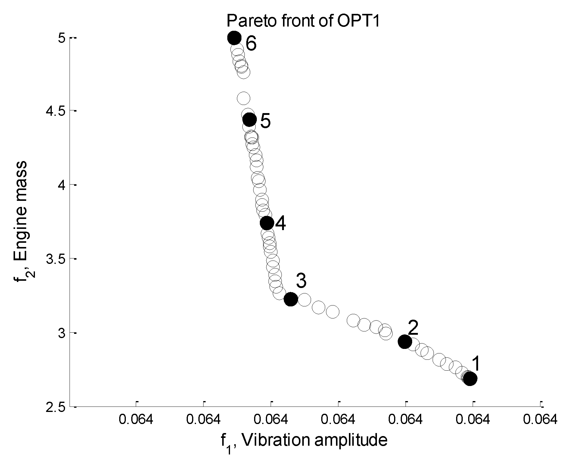
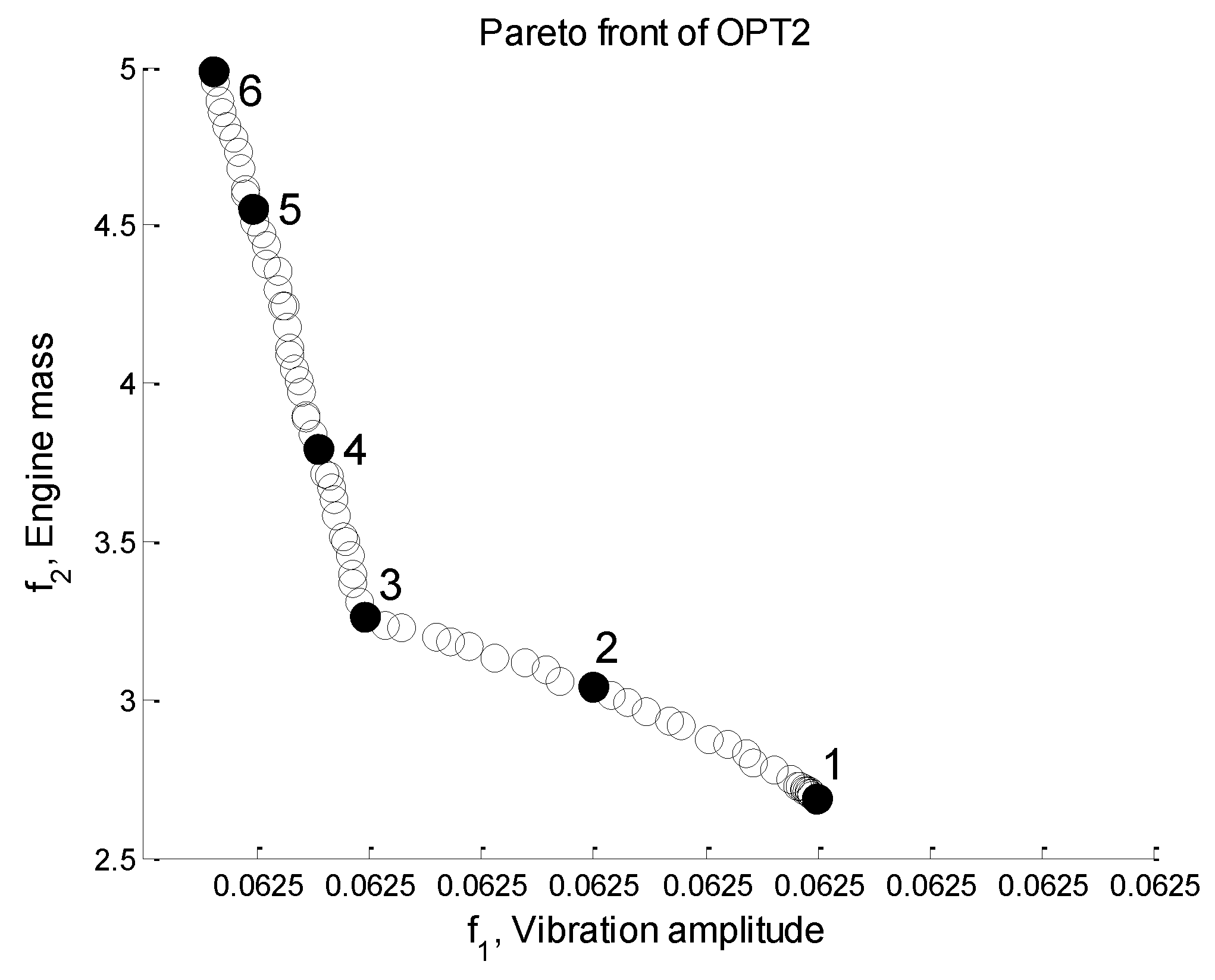
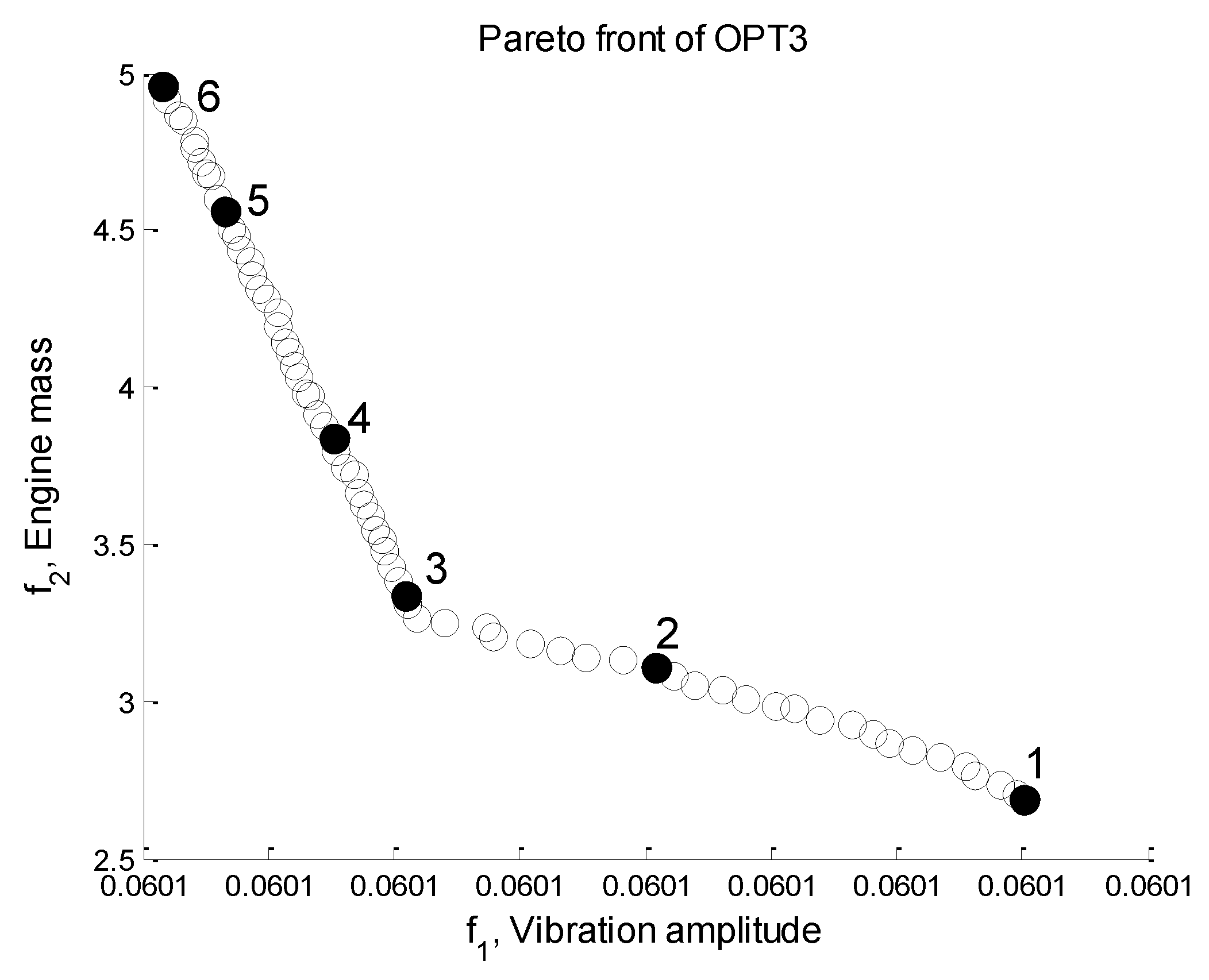
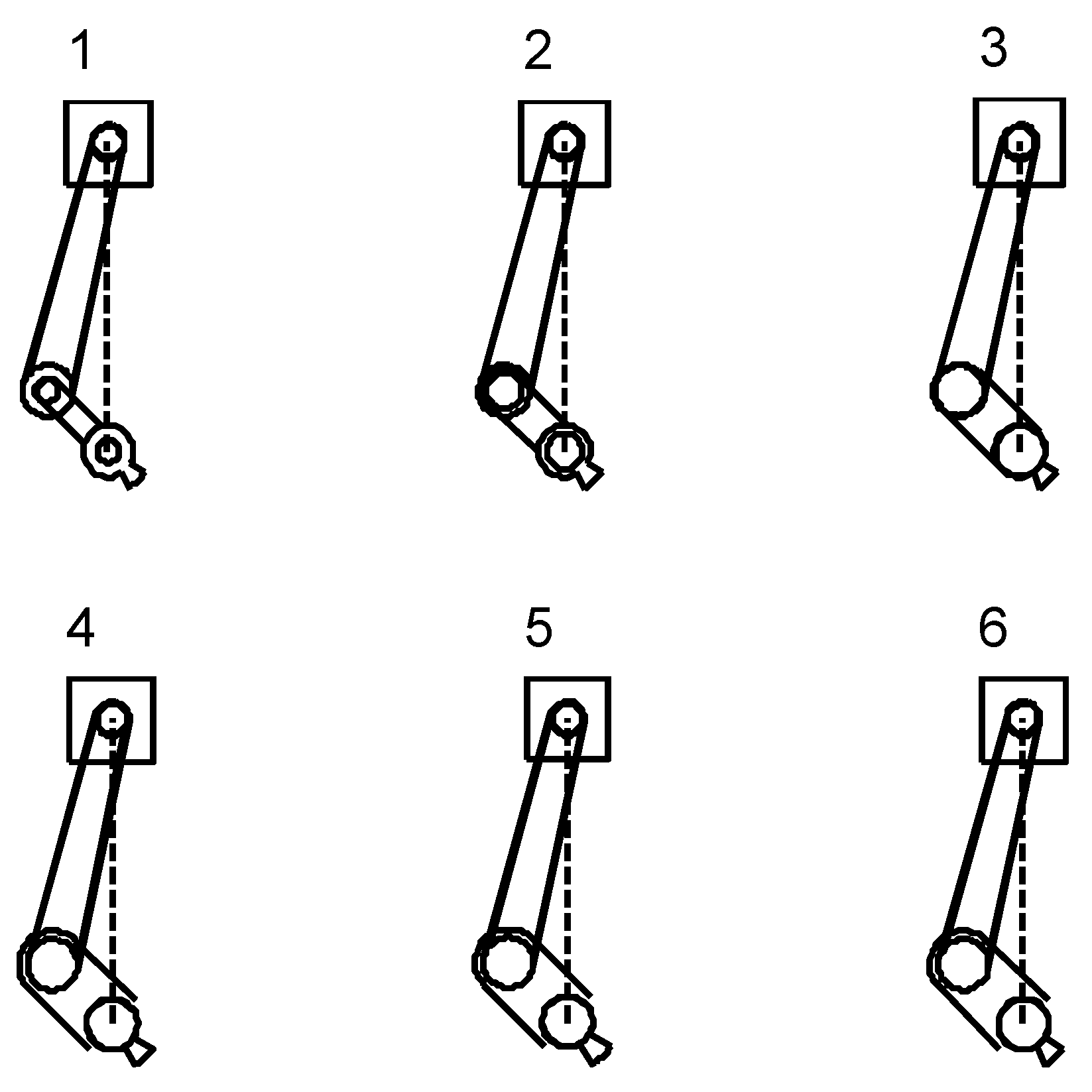
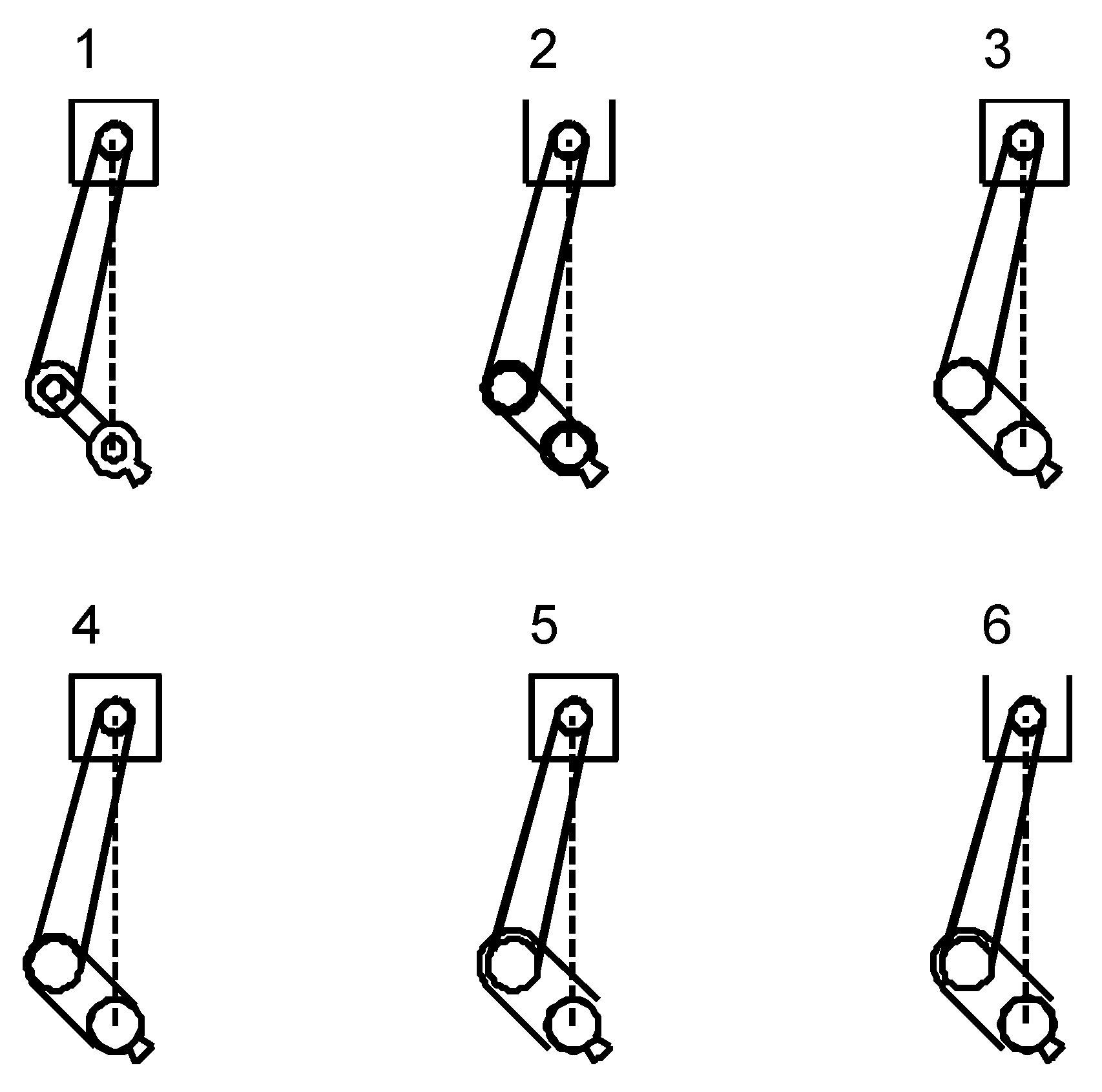
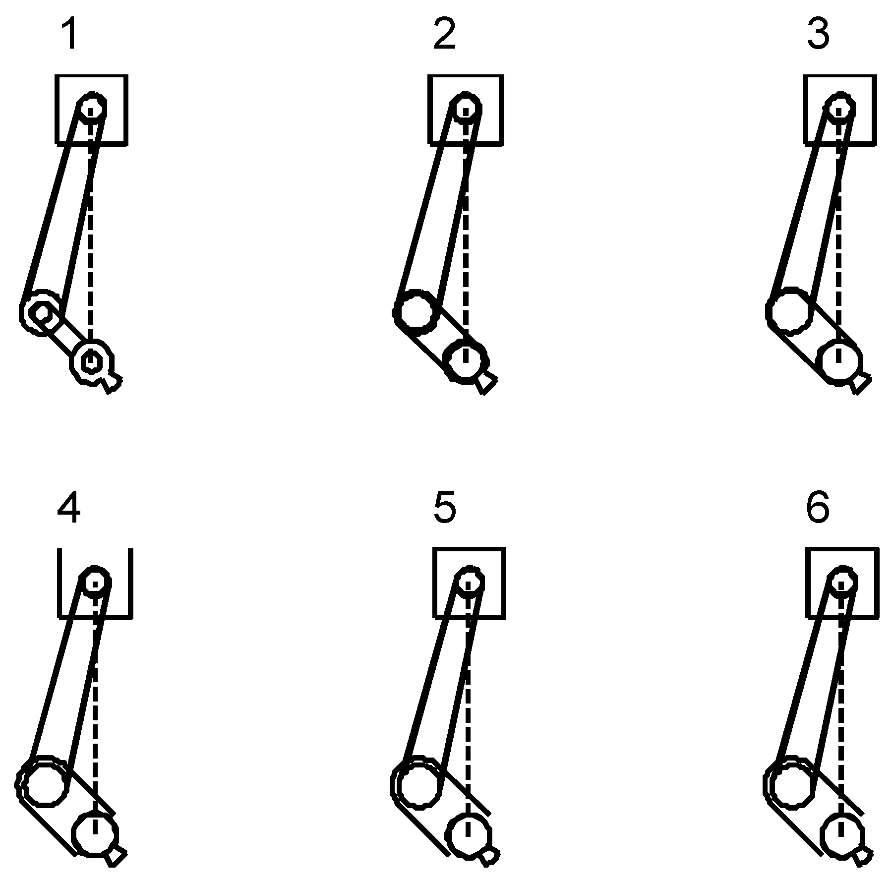
We implemented the RPBIL-DE for solving the design problems, ran 10 OPT1-3 runs, and chose the best front based on the hypervolume indicator of each design problem. According to its definition, the larger the hypervolume, the better the Pareto front. Figure 12, Figure 13 and Figure 14 show the best front at each engine speed. The results from minimising vibrations (RMS) and the mass of the single cylinder engine (kg) at the engine speed of 1000 rpm are in the ranges of [0.06402 0.06402] and [2.688 4.998] kg, respectively. The vibration and engine mass at the engine speed of 1500 rpm are in the ranges of [0.06252 0.06252] and [2.688 4.986] kg. At the engine speed of 2000 rpm, the results are in the ranges of [0.06012 0.06012] and [2.688 4.957] kg for vibration magnitude and engine mass, respectively. Some selected design solutions of each design problem in Figure 12, Figure 13 and Figure 14 and the corresponding crank–sliders of each front are illustrated in Figure 15, Figure 16 and Figure 17.
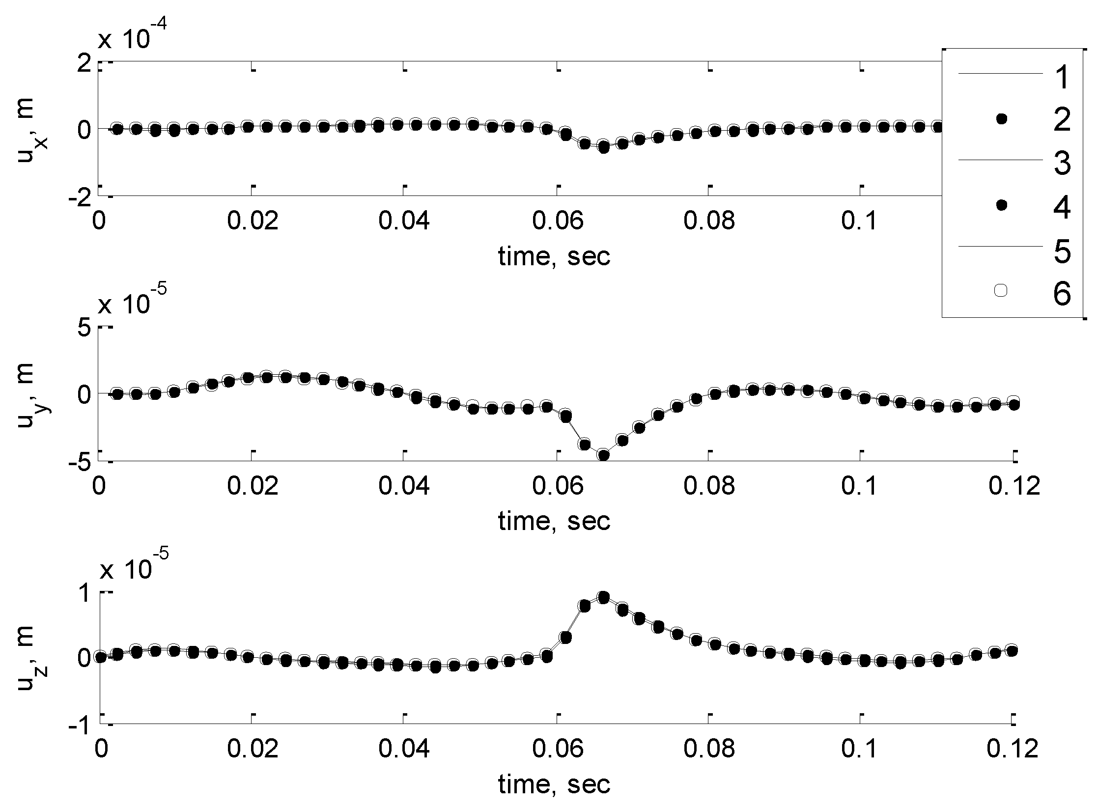
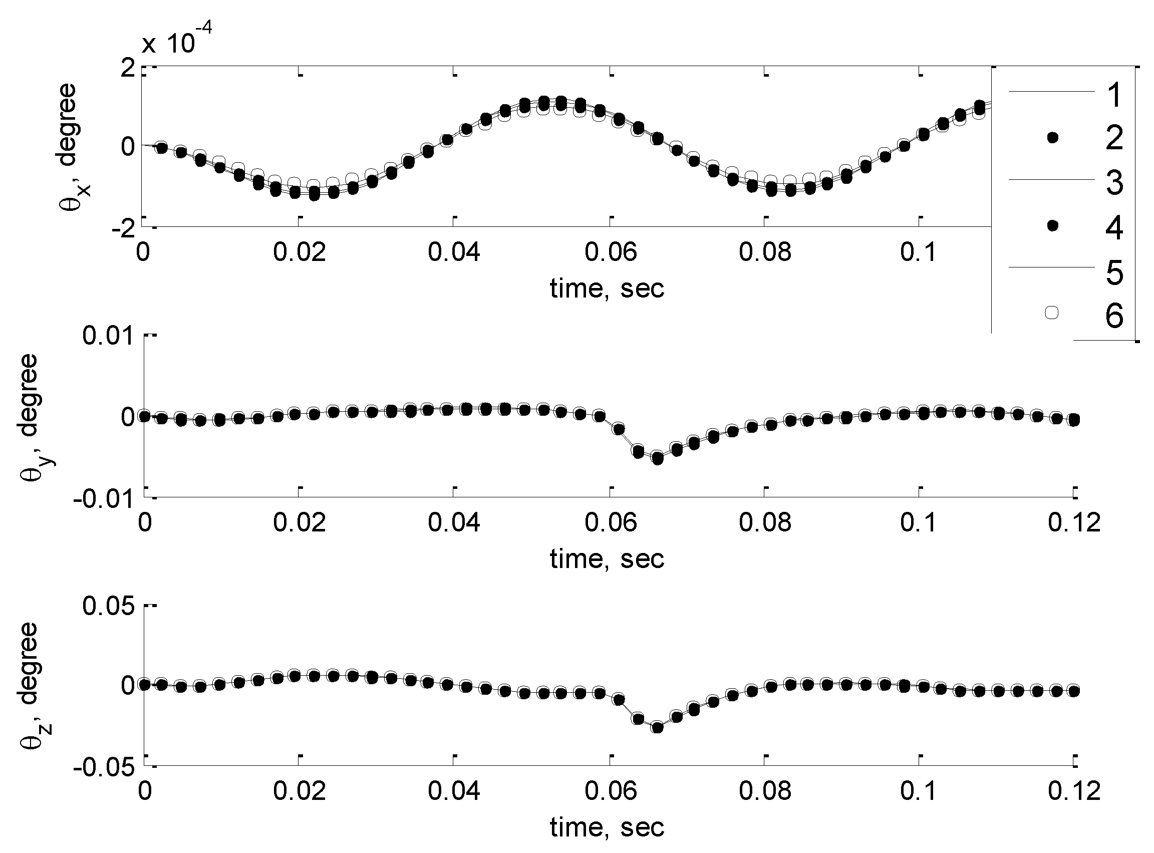
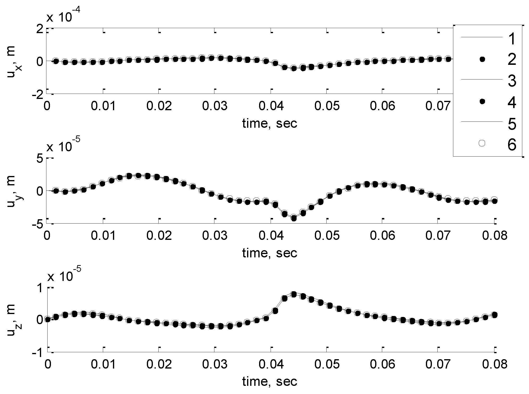
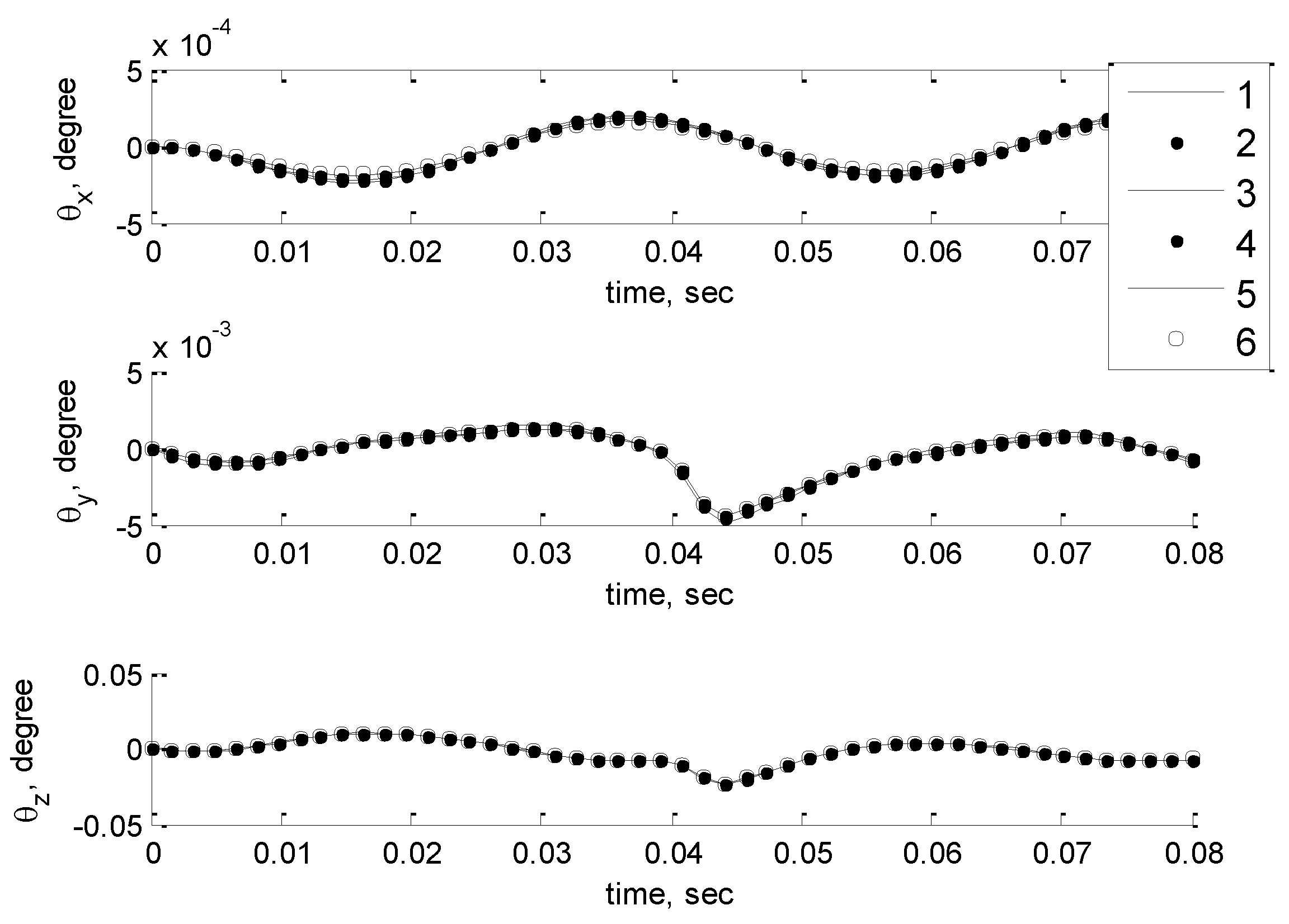
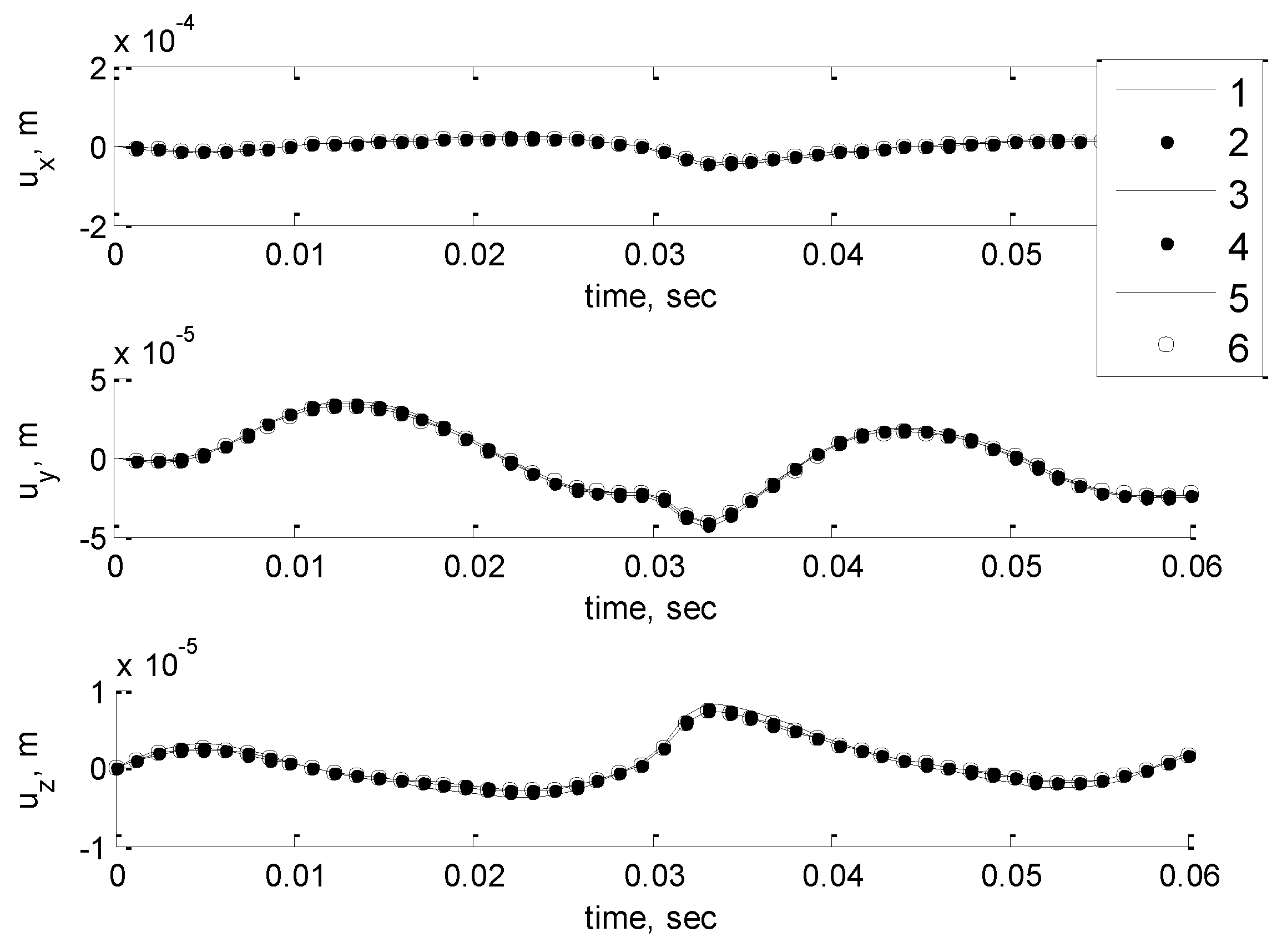
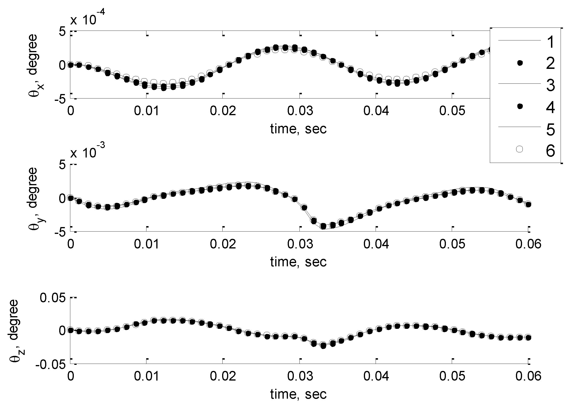
Dynamic analyses of the crank–sliders in Figure 15, Figure 16 and Figure 17 are carried out, and the results are shown in Figure 18, Figure 19, Figure 20, Figure 21, Figure 22 and Figure 23. Figure 18, Figure 20 and Figure 22 display the components of the translational displacements of the six engines, while Figure 19, Figure 21 and Figure 23 display the components of the rotational displacements of the six engines. From our design results, when focusing on vibration amplitude, it is found that our technique can control the vibration amplitude to oscillate in a small strip throughout the Pareto front, while the changing of mass is in accordance with the shape design parameters of the moving parts of a single cylinder.
7. Conclusions
The vibration suppression of a single-cylinder engine by means of multi-objective evolutionary optimisation is proposed. Simple kinematic and dynamic force analyses of a single cylinder are presented. The multi-objective design problems are posed to minimise the mass of the engine mechanism and vibration amplitudes of the engine system. We implemented RPBIL-DE to solve the design problems. The obtained design solutions are illustrated and analysed. The computation results reveal that the proposed design process for forming the moving parts of a single-cylinder engine is practical. Our technique can control the vibration amplitude to oscillate in a small strip throughout the Pareto front by optimisation of the moving parts of a single-cylinder engine. With the use of RPBIL-DE, multiple solutions for decision-making can be obtained within one optimisation run. Future work will be the use of three-dimensional finite element analysis for calculating the design constraints. This could be a time-consuming process, which may require a surrogate-assisted MOEA. Also, different shapes of the crank and connecting rod should be studied.
Author Contributions
Suwin Sleesongsom and Sujin Bureerat conceived and designed the numerical experiments; Suwin Sleesongsom performed the numerical experiments; Suwin Sleesongsom and Sujin Bureerat analyzed the data; Suwin Sleesongsom wrote the paper.
Acknowledgments
The authors are grateful for the financial support provided by the Thailand Research Fund, and King Mongkut’s Institute of Technology Ladkrabang.
Conflicts of Interest
The authors declare no conflict of interest.
References
- Paul, B. Kinematics and Dynamics of Planar Machinery; Pretice-Hall: New Jersey, NJ, USA, 1979. [Google Scholar]
- Lowen, G.G.; Tapper, F.R.; Berkof, R.S. Balancing of linkages-an update. Mech. Mach. Theory 1983, 18, 213–220. [Google Scholar] [CrossRef]
- Zhang, S.M.; Chen, J.H. The Optimum balance of shaking force and shaking moment of linkage. Mech. Mach. Theory 1994, 30, 589–597. [Google Scholar]
- Snyman, J.A.; Heyns, P.S.; Vermeulen, P.J. Vibration isolation of a mounted engine through optimization. Mech. Mach. Theory 1995, 30, 109–118. [Google Scholar] [CrossRef]
- Chiou, S.T.; Bai, G.J.; Chang, W.K. Optimum balancing designs of drag-link drive of mechanical presses for precision cutting. Int. J. Mach. Tools Manuf. 1998, 38, 131–141. [Google Scholar] [CrossRef]
- Sleesongsom, S. Vibration suppression of a single cylinder engine by using normalized normal constraint. In Proceedings of the TISD2006, Khon Kaen, Thailand, 25–27 January 2006; pp. 342–349. [Google Scholar]
- Messac, A.; Ismail-Yahaya, A.; Mattson, C.A. The normalized normal constraint method for generating the Pareto frontier. Struct. Multidiscip. Optim. 2002, 25, 86–98. [Google Scholar] [CrossRef]
- Asadi, M.R.; Rasekh, M.; Golmohammadi, A.; Jafari, A.; Kheiralipour, K.; Borghei, A.M. Optimization of connecting rod of MF-285 tractor. J. Agric. Technol. 2010, 6, 649–662. [Google Scholar]
- Cevik, M.; Kanpolat, E.; Rebbert, M. Shape Optimization of a Single Cylinder Engine Crankshaft; SAE Technical Paper 2011-01-1077; SAE: Detroit, MI, USA, 2011. [Google Scholar] [CrossRef]
- Lydia Mahanthi, D.; Venkata Siva Murali, C.; Mohan, R. Design Analysis and Optimization of a Four Stroke Single Cylinder Diesel Engine Piston. Imp. J. Interdiscip. Res. 2017, 3, 719–725. [Google Scholar]
- Ganguly, A.; Bhatia, N.; Agarwal, V.; Mohite, U. Balancing Optimization of a Motorcycle Engine Crankshaft for Vibration Reduction; SAE Technical Paper 2016-01-1060; SAE: Detroit, MI, USA, 2016. [Google Scholar]
- Spiekerman, C.E.; Radcliffe, C.J.; Goodman, E.D. Optimal design and simulation of vibration isolation system. J. Mech. Trans. Autom. Des. 1985, 107, 271–276. [Google Scholar] [CrossRef]
- Swanson, D.A.; Wu, H.T.; Ashrafiuon, H. Optimization of aircraft engine suspension systems. J. Aircr. 1993, 30, 978–984. [Google Scholar] [CrossRef]
- Liette, J.; Dreyer, J.T.; Singh, R. Critical examination of isolation system design paradigms for a coupled powertrain and frame: Partial torque roll axis decoupling methods given practical constraints. J. Sound Vib. 2014, 333, 7089–7108. [Google Scholar] [CrossRef]
- Qin, W.; Shangguan, W.Q.; Luo, G.; Luo, G.; Xie, Z. A method for estimating mount isolations of powertrain mounting systems. J. Sound Vib. 2018, 426, 278–295. [Google Scholar] [CrossRef]
- Tao, J.S.; Lui, G.R.; Lam, K.Y. Design optimization of marine engine-mount system. J. Sound Vib. 2000, 235, 477–494. [Google Scholar] [CrossRef]
- Kaul, S.; Dhingra, A.K. Kriging modeling for engine mount optimization in motorcycles. In Proceedings of the IMECE2009, Lake Buena Vista, FL, USA, 13–19 November 2009; pp. 1–12. [Google Scholar]
- Fan, R.L.; Wang, J.Z.; Lu, Z.H. Vibration isolation optimization for automotive engine mounting system. Trans. Chin. Soc. Intern. Combust. Eng. 2010, 28, 269–274. [Google Scholar]
- Li, Q.; Zhao, J.C.; Zhao, B.; Zhu, X.S. Parameter optimization of a hydraulic engine mount based on a genetic neural network. Proc. Inst. Mech. Eng. Part D J. Automob. Eng. 2009, 223, 1109–1117. [Google Scholar] [CrossRef]
- Lee, D.H.; Hwang, W.S.; Kim, C.M. Design sensitivity analysis and optimization of an engine mount system using an FRF-based substructuring method. J. Sound Vib. 2002, 255, 383–397. [Google Scholar] [CrossRef]
- Ohadi, A.R.; Maghsoodi, G. Simulation of engine vibration on nonlinear hydraulic engine mounts. J. Vib. Acoust. 2007, 129, 417–424. [Google Scholar] [CrossRef]
- Bi, F.R.; Du, X.F.; Shao, K.; Zhang, J.H. Block design of diesel engine for low vibration based on topography optimization. Trans. Chin. Soc. Intern. Combust. Eng. 2010, 28, 459–463. [Google Scholar]
- Jia, W.X.; Hao, Z.Y.; Xu, H.M. Light-weight design of single cylinder engine block based on structure optimization. J. Zhejiang Univ. 2008, 2, 224. [Google Scholar]
- Ayarani-N, M.H.; Yao, X.; Xu, H. Meta-heuristic algorithms in car engine design: A literature survey. IEEE Trans. Evol. Comput. 2015, 19, 609–629. [Google Scholar] [CrossRef]
- Ma, F.; Yin, H.; Wei, L.; Tian, G.; Gao, H. Design and optimization of IPM motor considering flux weakening capability and vibration for electric vehicle application. Sustainability 2018, 10, 1533. [Google Scholar] [CrossRef]
- Newmark’s Method of Direct Integration. Available online: http://www.softeng.rl.ac.uk/st/projects/felib3/Docs/html/Intro/intro-node52.html (accessed on 25 May 2018).
- Pholdee, N.; Bureerat, S. Hybridisation of real-code population-based incremental learning and differential evolution for multiobjective design of trusses. Inf. Sci. 2013, 223, 136–152. [Google Scholar] [CrossRef]
- Pholdee, N.; Bureerat, S. Hybrid real-code population-based incremental learning and approximate gradients for multi-objective truss design. Eng. Optim. 2014, 46, 1032–1051. [Google Scholar] [CrossRef]
- Sleesongsom, S.; Bureerat, S. Multiobjective optimization of a steering linkage. J. Mech. Sci. Technol. 2016, 30, 3681–3691. [Google Scholar] [CrossRef]
- Sleesongsom, S.; Bureerat, S. Optimization of Steering Linkage Including the Effect of McPherson Strut Front Suspension. Lect. Notes Comput. Sci. 2018, 10941, 612–623. [Google Scholar]
- Bureerat, S. Hybrid population-based incremental learning using real codes. Lect. Notes Comput. Sci. 2011, 6683, 379–391. [Google Scholar]
- Das, S.; Suganthan, P.N. Differential evolution: A survey of the state-of-the-art. IEEE Trans. Evolut. Comput. 2011, 15, 4–31. [Google Scholar] [CrossRef]
- Bandyopadhyay, S.; Saha, S.; Maulik, U.; Deb, K. A simulated annealing-based multiobjective optimization algorithm: AMOSA. IEEE Trans. Evolut. Comput. 2008, 12, 269–283. [Google Scholar] [CrossRef]
- Muravyov, A.; Hutton, S.G. Analysis of an engine-mount system with time-dependent mass and velocity matrix. J. Sound Vib. 1998, 209, 143–162. [Google Scholar] [CrossRef]
- Deb, K.; Pratap, A.; Meyarivan, T. Constrained test problems for multi-objective evolutionary optimization. Lect. Notes Comput. Sci. 2001, 1993/2001, 284–298. [Google Scholar]
Figure 1.
Single-cylinder engine model.

Figure 2.
Free-body diagram of a crank–slider.

Figure 3.
Spring displacement vector in three-dimensional spaces.

Figure 4.
Vector position of spring position relative tothe center of mass.

Figure 5.
Degree of freedom of rigid body in three-dimensional spaces.

Figure 6.
A single-cylinder engine and its engine box.

Figure 7.
Model of crank and design parameters.

Figure 8.
Model of the connecting rod and design parameters.

Figure 9.
Gas pressure force versus crank angle at 1000 rpm.

Figure 10.
Inertia force due to crank slider versus crank angle at 1000 rpm.

Figure 11.
Total force due to gas pressure force and inertia force versus crank angle at 1000 rpm.

Figure 12.
The best Pareto front of OPT1.

Figure 13.
The best Pareto front of OPT2.

Figure 14.
The best Pareto front of OPT3.

Figure 15.
Some selected design solutions of OPT1.

Figure 16.
Some selected design solutions of OPT2.

Figure 17.
Some selected design solutions of OPT3.

Figure 18.
The components of the translational displacements of the six engines in Figure 15.
Figure 18.
The components of the translational displacements of the six engines in Figure 15.

Figure 19.
The components of the rotational displacements of the six engines in Figure 15.
Figure 19.
The components of the rotational displacements of the six engines in Figure 15.

Figure 20.
The components of the translational displacements of the six engines in Figure 16.
Figure 20.
The components of the translational displacements of the six engines in Figure 16.

Figure 21.
The components of the rotational displacements of the six engines in Figure 16.
Figure 21.
The components of the rotational displacements of the six engines in Figure 16.

Figure 22.
The components of the translational displacements of the six engines in Figure 17.
Figure 22.
The components of the translational displacements of the six engines in Figure 17.

Figure 23.
The components of the rotational displacements of the six engines in Figure 17.
Figure 23.
The components of the rotational displacements of the six engines in Figure 17.


Table 1.
System parameters.
| Parameters | Symbols | Quantities |
|---|---|---|
| Total engine mass | m | 14.528 kg |
| Piston mass | m4 | 0.2 kg |
| Moment of inertia | Ixx, Iyy, Izz, Ixy, Ixz, Iyz | 0.0768, 0.0640, 0.0812, 0, 0, 0 kg-m2 |
| Centre of gravity | RG | [0,0,0]T m |
| Crank shaft centre | RO/G | [−0.760, −0.0232, 0.0100]T m |
| Mount stiffness | k | 4 × 10⁶ N/m |
| Crank length | R | 0.1 m |
| Connecting rod length | L | 0.3 m |
| Material density | ρ | 7850 kg/m3 |
| Piston diameter | d | 100 mm |
© 2018 by the authors. Licensee MDPI, Basel, Switzerland. This article is an open access article distributed under the terms and conditions of the Creative Commons Attribution (CC BY) license (http://creativecommons.org/licenses/by/4.0/).
Share and Cite
MDPI and ACS Style
Sleesongsom, S.; Bureerat, S. Vibration Suppression of a Single-Cylinder Engine by Means of Multi-objective Evolutionary Optimisation. Sustainability 2018, 10, 2067. https://doi.org/10.3390/su10062067
AMA Style
Sleesongsom S, Bureerat S. Vibration Suppression of a Single-Cylinder Engine by Means of Multi-objective Evolutionary Optimisation. Sustainability. 2018; 10(6):2067. https://doi.org/10.3390/su10062067
Chicago/Turabian StyleSleesongsom, Suwin, and Sujin Bureerat. 2018. "Vibration Suppression of a Single-Cylinder Engine by Means of Multi-objective Evolutionary Optimisation" Sustainability 10, no. 6: 2067. https://doi.org/10.3390/su10062067
Note that from the first issue of 2016, this journal uses article numbers instead of page numbers. See further details here.