Comparative Study of Passive and Active Islanding Detection Methods for PV Grid-Connected Systems


1
Department of Electrical Engineering, College of Engineering, Majmaah University, Al Majmaah 11952, Saudi Arabia
2
Electrical Engineering Department, Assiut University, Assiut 71515, Egypt
*
Author to whom correspondence should be addressed.
Sustainability 2018, 10(6), 1798; https://doi.org/10.3390/su10061798
Submission received: 17 April 2018
/
Revised: 23 May 2018
/
Accepted: 26 May 2018
/
Published: 30 May 2018
(This article belongs to the Section Energy Sustainability)
Abstract
:Photovoltaic (PV) power grid-connected systems have the advantages of being prompt and reliable supplies of electrical power. Nevertheless, the installation and operation requirements from the grid side have to be fulfilled in order to guarantee the security of the PV system technicians and the efficiency of the power system. Particularly, the potential for “islanding” is one of the dreads that are brought about by PV grid-connected systems. To be able to tackle these concerns, this paper investigates recent islanding detection techniques and topologies for PV systems. Active islanding detection techniques apply regular disturbances to the inverter system and then analyze the output voltage or frequency to investigate the islanding and stability of the grid. If the injected disturbances influence the load voltage or frequency, the controller forces the intermediate inverter to stop sending power to the connected load. In addition, several islanding detection techniques that inject a periodical signal to the reference current that causes a change in the magnitude of inverter output voltage when islanding happens in a three-phase photovoltaic grid-connected system are discussed. The validity of the proposed technique is tested and verified through PSIM software.
1. Introduction
Recently, the distributed generation (DG) system has witnessed increasing contributions in the field of power generation all over the world. Nowadays, various DG systems have penetrated power generation systems for the smart grid, which introduces the bi-directional flow of electricity and information, protects the electric machines and equipment from a complete failure caused by natural disasters and wrong operations, and enhances the system reliability, security, and efficiency of generation, transmission, and distribution [1,2,3]. On the other hand, the increasing penetration of DGs impose challenges on the existing distribution infrastructure such as power coordination, anti-islanding, voltage harmonics, and voltage regulation problems. In a micro-grid with several DGs, the optimum operation of the power and voltage controllers can be obtained by controlling the islanding operations.
According to IEEE standards, the grid-connected inverter should use an islanding detection technique. The grid parameters threshold values of the STD 929 and STD 1547 standards are given in References [4,5,6]. The voltage limits are divided into ranges and the trip time for each range is defined in each standard. The normal operating range for the frequency is the same in both standards as are the current harmonic distortion limits.
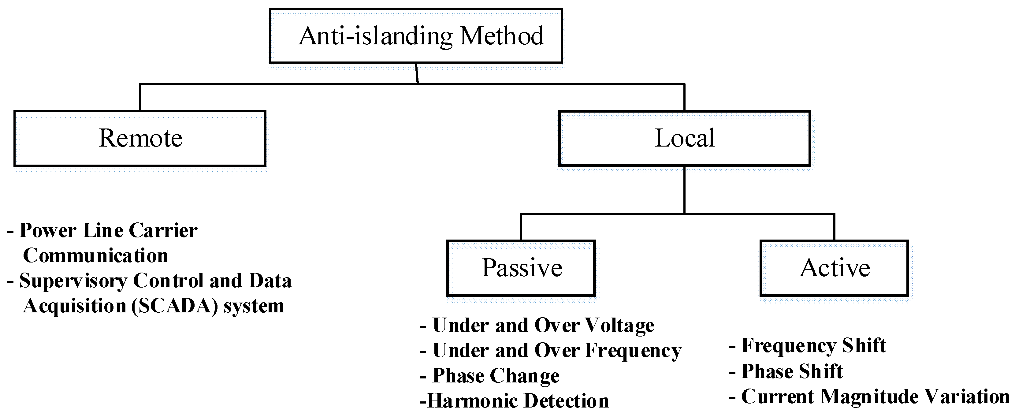
Different algorithms have been used in the last decade or so. All the existing methods can be broadly divided into 3 categories as shown in Figure 1 and summarized as follows:
- -
- passive methods;
- -
- active methods;
- -
- communications-based methods.
This paper is divided into two parts. The first part surveys the existed islanding detection methods and presents the theory of operation of several passive and active islanding detection methods in grid-connected PV systems. The second part introduces an inverter current reference perturbation algorithm for a three-phase grid-connected PV system for islanding detection. The injected signal periodically perturbs the reference current with the same amount of positive and negative components. This keeps the mean PV output power unchanged during the perturbation time. When the grid connection is lost, the magnitude of the Point of Common Coupling (PCC) voltage deviates because of the current magnitude perturbation. To implement the proposed method, a grid-connected PV system is designed and used. The validation of the proposed control algorithms is applied through the PSIM software.
2. Islanding Detection Methods
2.1. Passive Islanding Methods
The passive techniques look for some parameter deviations like voltage magnitude [7], rate of change of frequency [8], harmonics [9], or Phase angle displacement [10]. In the islanding mode, these parameters vary largely at the PCC. The difference between the grid-connected and islanding mode depends on the setting of the threshold values. A lower setting for the threshold for the permissible disturbances in these quantities may cause nuisance tripping. On the other hand, if the setting is too high, then the protective devices will not respond to the islanding condition. The merits of these methods are the fast response and the absence of system disturbances. However, these methods have the disadvantage of having a large non-detectable zone (NDZ) and these protective methodologies might have variable or unpredictable reaction times. More specific passive anti-islanding methods can be discussed as follows:
2.1.1. Under/over Voltage and under/over Frequency
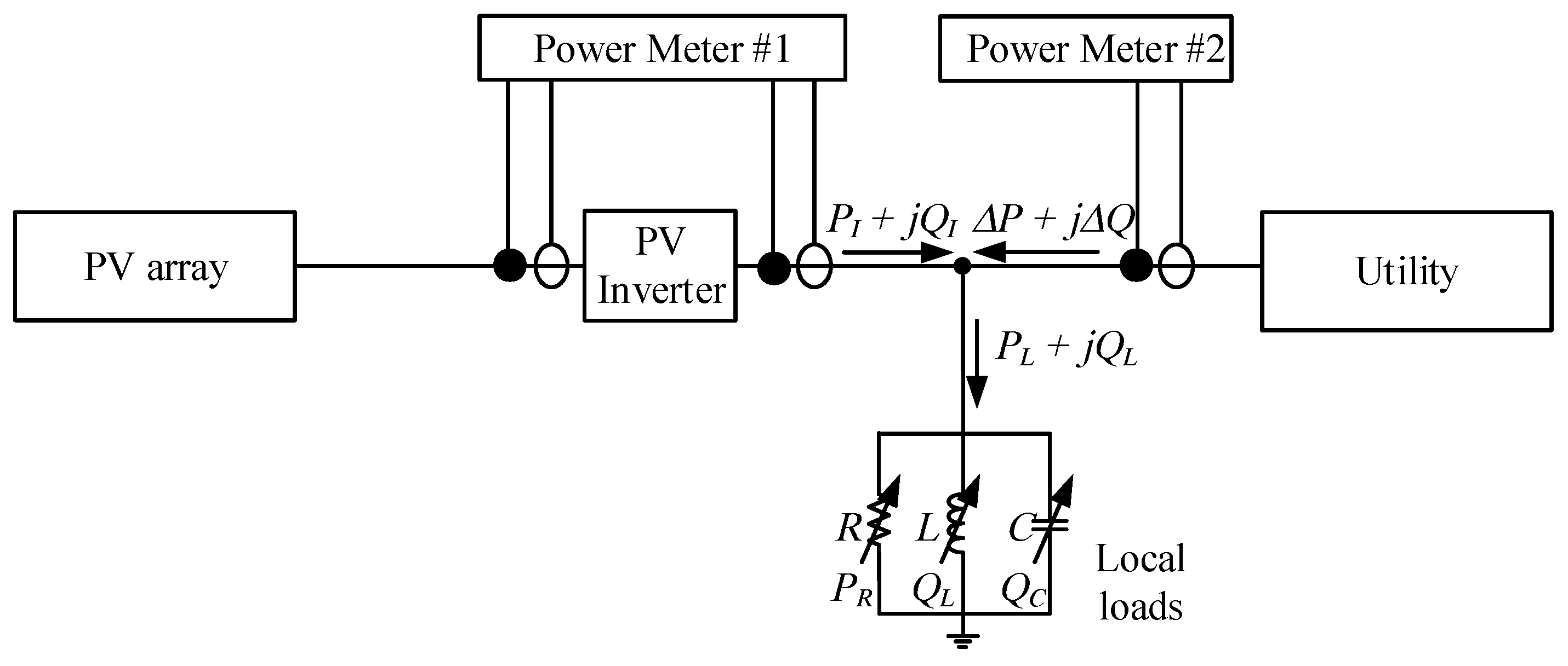
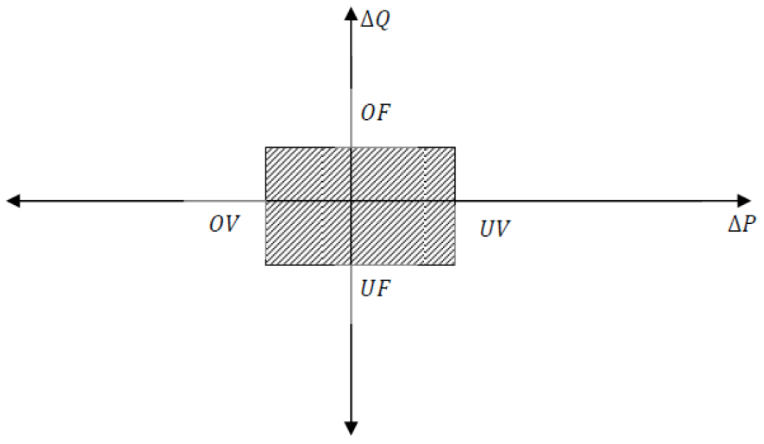
Under/over frequency protection techniques (UOF) and under/over voltage protection techniques (UOV) are required for all grid-connected PV inverters. These UOF/UOV protective devices are used as anti-islanding detection techniques and also used to protect the equipment of customers. In Figure 2, the system configuration of a PV inverter that is connected to a variable load is shown. When the PV-inverter is connected to the grid, the active and reactive powers (Pt + jQt) are delivered by the PV. If the PV power rating is lower than the load power, then the power differences (ΔP and ΔQ) will be supplied from the utility grid. In the case of islanding, a mismatch of some parameters as voltage and frequency will occur. This behavior of this method may vary depending on ΔP and ΔQ. For more details, if ΔP is not equal to zero then the voltage amplitude at PCC will deviate and the islanding will be detected by the UOV protective relay. Similarly, the phase voltage at PCC changes when ΔQ is not equal to zero, causing a frequency deviation. Additionally, the UOF protection relays will then detect these variations and, consequently, islanding will commence. If the power differences are too large, both voltage and frequency exceed the adjusted limits of the UOF/UOV protective devices, which ultimately trips the circuit breaker. In cases of small differences between the load power and the PV output power, this method may not be able to detect islanding due to the large NDZ. An example of NDZ is given in Figure 3; the mismatch regions of the power components are represented by the shaded area where this method cannot detect the islanding events [9,11,12,13,14].
2.1.2. Harmonics Detection Method
The Harmonics Detection method concept is based on monitoring the Total Harmonic Distortion (THD) of the PCC voltage to determine whether islanding occurs. In normal operation, the impedance of the power grid is small; the inverter current harmonic component mainly flows into the grid. The PCC voltage is decided by the utility-grid voltage and, usually, the voltage harmonic content is small. When the power supply is disconnected due to the non-linear characteristics, the non-linear load harmonic current flowing into the inverter will also have large harmonics because the non-linearity of the transformer hysteresis output current produces a distortion voltage in the transformer. The islanding conditions can be decided by detecting the harmonic distortion of the output voltage.
This method has several advantages: it is simple, viable, and has a high detection accuracy. It does not influence the power quality and the detection range is wide; the change of the detection effect is not yet investigated under the parallel operation condition of the inverters; the islanding detection during the power match with a load is still very high.
The disadvantages of this method are as follows: a large amount of network voltage harmonics due to the non-linear load causes significant limitations and difficulties in practice. This method has an NDZ [15].
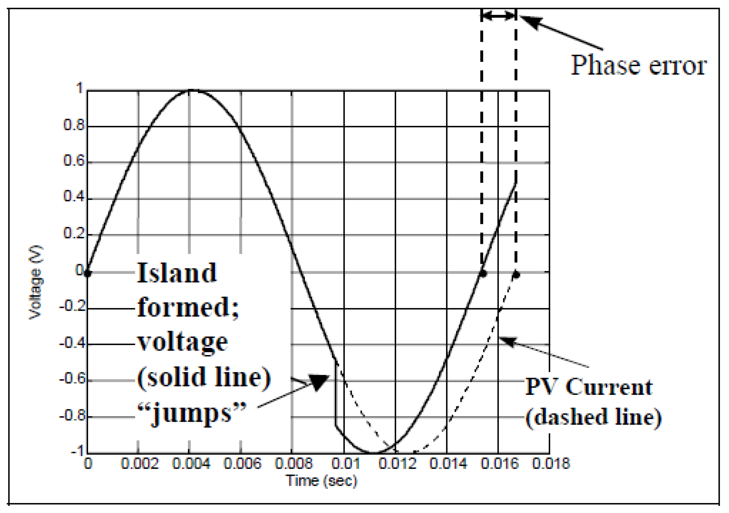
2.1.3. Phase Monitoring Method
The phase monitoring method is based on detecting any abrupt “jumps” in the phase shift between the terminal voltage of the inverter and its output current, as shown in Figure 4. However, when a fast Phase Locked Loop (PLL) is implemented, this phase jump would not be detected since the inverter terminal voltage and current are always in phase. Therefore, this method is presented to enhance the phase jump technique. Under the normal condition, the inverter produces zero reactive power and the phase angle between the terminal voltage and the output current at PV inverter terminals is zero. During the islanding condition, a displacement in the phase takes place because of the shift of the voltage vector. After a few cycles, the measured angle is compared with the detected angle, hence,
The calculated load phase angle is given by the following equation:
When the grid power is disconnected and the load frequency is as the same as the frequency of the grid, remains at zero without any change in the phase angle of the output current. In contrast, if the load and grid frequencies are not same, the phase differences and differs from zero. The resulting phase change is then used to detect the islanding condition. When that phase change exceeds the threshold, the controller will turn off the inverter.
The accuracy of this method is highly affected by the reactive elements of the power circuit. However, the output power quality of the inverter and the system dynamics are not affected. The effectiveness of phase monitoring is not affected when the parallel inverters are connected to the islanded system [9].
2.1.4. Change Detection of Key Power
When islanding occurs, due to the instability of the system, frequency, power oscillations, and their rate of change, this method continuously monitors the power, frequency rate, harmonic distortion, and the partial derivative of the frequency with respect to power. The second step is to compare these variables with the limit values and then detect the islanding condition [16,17,18].
2.1.5. Change of Frequency with Respect to Power df/dp
In this method, the islanding detection implemented by monitoring the rate of frequency change over power df/dp because the small power generation capacity system df/dp is greater than that in the larger power generation capacity. In the condition in which the local load and the capacity of DG are equal, df/dp will be more accurate than df/dt to detect islanding [19,20].
All the above-stated methods belong to the passive detection methods and their characteristics are almost the same. These methods commonly monitor other electrical quantities to enhance the detection performance. However, the need to measure these quantities leads to an increase in the cost of measurement [21,22].
Practically, to achieve the purposes of anti-islanding protection, one or several islanding detection methods can be used [23]. Islanding detection methods are classified together, even though they have different principles.
2.2. Active Islanding Detection Methods
Active islanding methods (AIMs) send and receive a periodical perturbation signal between the PV inverter and grid to make sure that the inverter is still connected to the power grid. That is to say, with this method, even a small disturbance signal will become clear and noticeable when inferring the islanding mode of operation so that the inverter will deal with the power change [24]. On the other hand, these methods, which depend on using disturbance signals, degrade the power quality because they can cause a variation in the magnitude of the inverter output current or output frequency.
The PV inverter output current is given by the following equation [25]:
where f is the frequency, Im is the inverter current amplitude, and θ is the initial phase angle. All the perturbation signals can be set or modified based on these three parameters. More specific AIMs can be discussed as follow:
2.2.1. Active Frequency Drift (AFD)
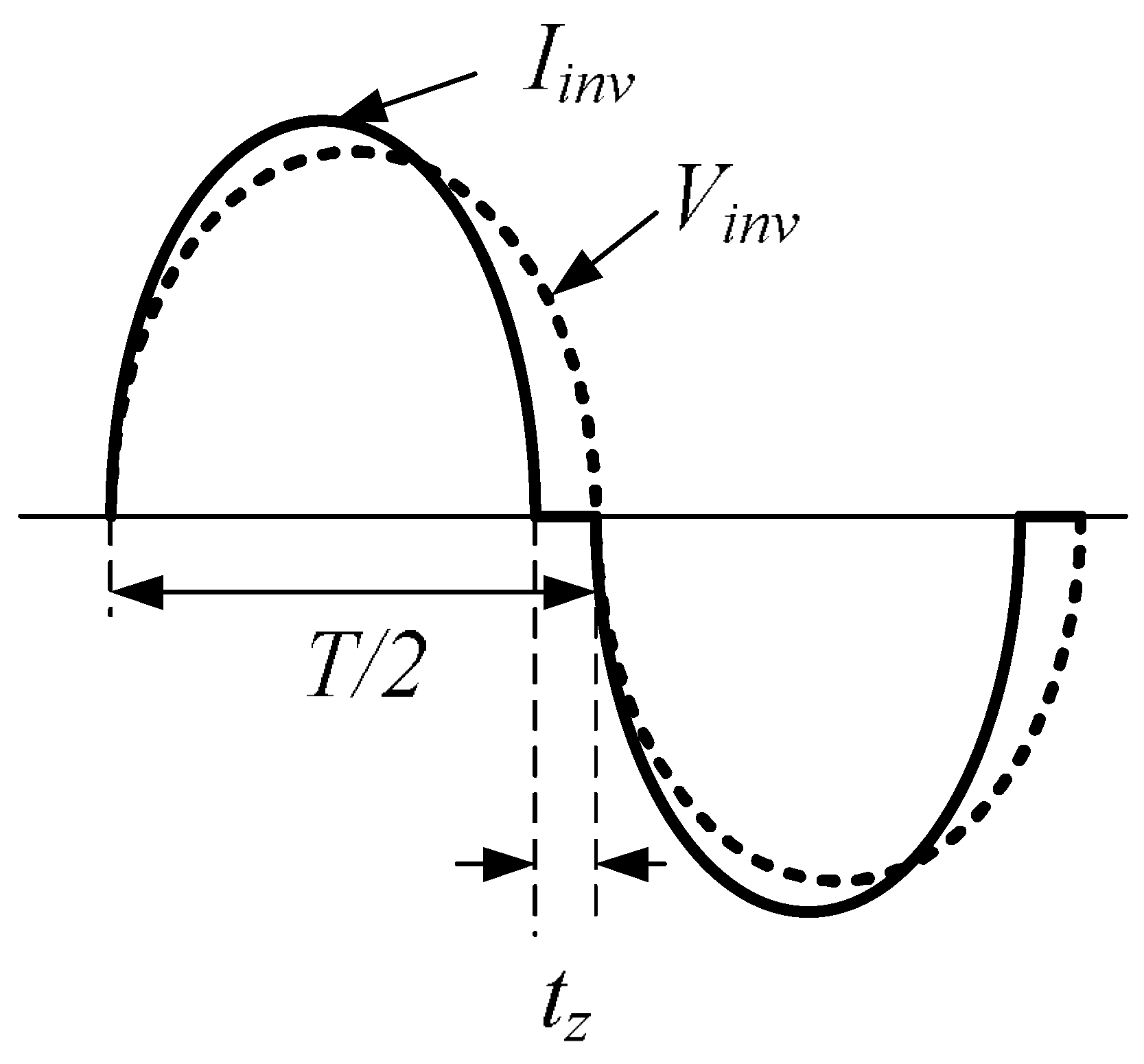
In this method, a small disturbance current signal is added to the inverter reference output current to disturb its output voltage. In the grid-connected mode, this distortion does not affect any of the inverter output voltages and frequencies, but in the grid-disconnected mode, this perturbation affects the inverter output frequency and, hence, this change in frequency may force the UOF to disconnect the DG. Therefore, the AFD method adds a zero-conduction time into each half cycle of the current waveform, as shown in Figure 5. If T is the utility voltage period and tz is the zero time, the ratio of tz to T/2 is defined as the “chopping fraction” Cf, which is used to characterize the intensity of the disturbance:
In the grid-disconnected mode, the inverter output power factor is normally unity and will have the same grid frequency. During the islanding condition, the introduced distortion to the current reference will introduce a constant drift in the inverter frequency, which will finally reach the frequency boundary limits set for the islanding detection.
2.2.2. Slip-Mode Frequency Shift (SMS)
SMS introduces a positive feedback to destabilize the inverter output for islanding detection. The phase of the inverter output current changes relative to the grid voltage that makes the voltage frequency at the PCC deviate from the nominal value once the grid has disconnected. Compared to other active techniques, SMS has a small NDZ and is very effective in the prevention of islanding. However, this method has some issues such as a transient response and power quality at very high penetration levels and feedback loop gains. This is a similar issue in all the methods that utilize positive feedback.
SMS also introduces a phase shift perturbation which can lead to noise, measurement error, and quantization error. This limitation can be answered by introducing an extra phase shift called the improved-SMS (IM-SMS). The IM-SMS was verified through digital simulation and experimentation, which resulted in a high reliability, easy implementation, and simplicity [9].
2.2.3. Impedance Measurement
The impedance measurement method is somehow similar to a passive technique, which measures the system impedance variations caused by islanding. In AIMs, however, a parallel inductor is temporarily connected across the utility grid. The inductor current and supply voltage reduction are used to calculate the power source impedance [40]. The impedance measurement methods have recently been used because of the belief that they have no NDZ, especially in the single-inverter case.
Therefore, the experimental studies verify the robustness of the impedance measurement test based on the islanding detection in a single-inverter case [41]. The experiment shows that the impedance measurement method based on islanding detection does have an NDZ in the single-inverter systems. However, this method has the main disadvantage; in the case of parallel multiple inverters, each one would be forcing a slightly different signal into the line.
Ensuring that the inverter maximum power point MPPT is enabled with impedance detection is important because the impedance measurement islanding detection method is reliable for large or small duty ratios. The accuracy of this method in the single-inverter case is highly improved by the addition of a variable length phase shift. This enhancement produces a small number of sub-harmonics in the PV inverter output. Therefore, other active techniques can be used to overcome the limitation of impedance measurement methods.
2.2.4. Sandia Frequency Shift (SFS)
SFS is basically a modified form of the AFD method. SFS uses positive feedback by introducing a little phase shift at the inverter output current through adding dead-conduction times to the inverter reference current. Therefore, the frequency of the inverter current will deviate from the power system frequency. The chopping frequency shown in Equation (4) is intended to be proportional to the difference between the grid and the measured frequency.
where K is an accelerating gain, Cf0 is the chopping frequency, f is the grid frequency, and f0 is the measured frequency of the inverter output voltage. The chopping frequency becomes low when the frequency error is zero because the utility grid stabilizes the PCC voltage by giving a concrete reference for frequency and phase. The phase error between the inverter output voltage and current waveforms arise when the utility grid is lost.
This causes an increase in the inverter output current in order to overcome this phase shift. Due to the continuously increasing phase error, the chopping frequency also increases at the same time and the inverter still detects a phase error and keeps on increasing it far from the frequency. As a result, the value of the chopping frequency increases, the frequency drifts so far from f0 that the under and over frequency protection systems detect this and stop the inverter operation [42,43,44,45,46,47,48].
2.2.5. Sandia Voltage Shift (SVS)
Islanding is prevented by the Sandia Voltage Shift (SVS) with a positive feedback method, which is based on the voltage amplitude at the PCC. There will be little or no effect on the system power when the utility grid link is maintained. However, once the link of the utility grid is broken, there is a reduction in the PCC voltage. As per the load impedance’s relationship, this reduction continues, which results in the reduction of the current and output power. Therefore, the under voltage protection system can detect this reduction in the amplitude of the PCC voltage. It is possible to either decrease or increase the inverter output power, which leads to a tripping of the corresponding under and over voltage protection systems and the cease of the operation of the inverter [49,50,51,52].
2.2.6. Detection of Impedance at the Specific Frequency
In this technique, a low frequency current harmonic is intentionally injected into the PCC. During the connection of the grid, if the impedance at the harmonic frequency is much lower than the load impedance, then the harmonic current flows into the grid and the voltage abnormality is observed. When the utility is disconnected, then the harmonic current has only one way to flow, which is the terminal load. This method’s name is derived from the relationship between the amplitude of the produced harmonic voltage and load impedance at the harmonic current frequency.
3. Proposed Islanding Method
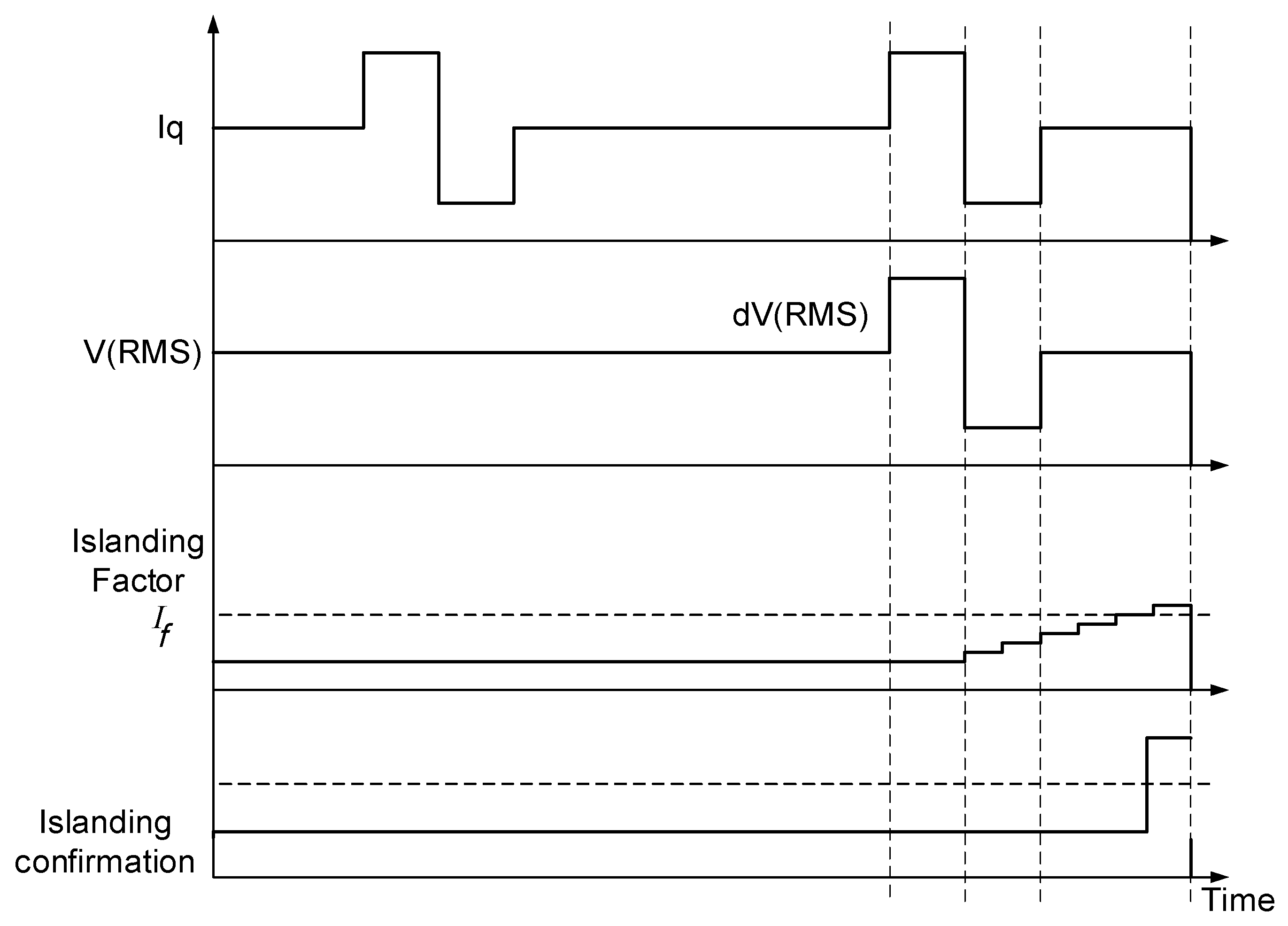
The system considered in the proposed islanding detection periodically perturbs the inverter reference q-axis current to be 10% more than the current reference value at one line cycle and, in the next line cycle, the current reference value is decreased by the same value, as shown in Figure 6. This method maintains the inverter average output power to be constant so as to not deteriorate the MPPT process. For several cycles, the reference current command is set to be nominal without perturbation. This process is implemented regularly with the same intervals as shown in Figure 6. In a string of consecutive line cycles, if the measured RMS output voltage is different from the nominal value, the islanding factor is incremented steadily to the maximum value in which the inverter is tripped.
The islanding factor is set to zero during the grid connection time when the rigid grid voltage forces the inverter terminal voltage to be equal to the grid voltage. On the other hand, without perturbing the current, the inverter voltage remains unchanged during the islanding mode. Therefore, the increases and decreases in the reference current make the RMS output voltage deviate from the nominal value when the grid is lost. As a result, the islanding factor increases and the inverter is deactivated when the factor exceeds the threshold value.
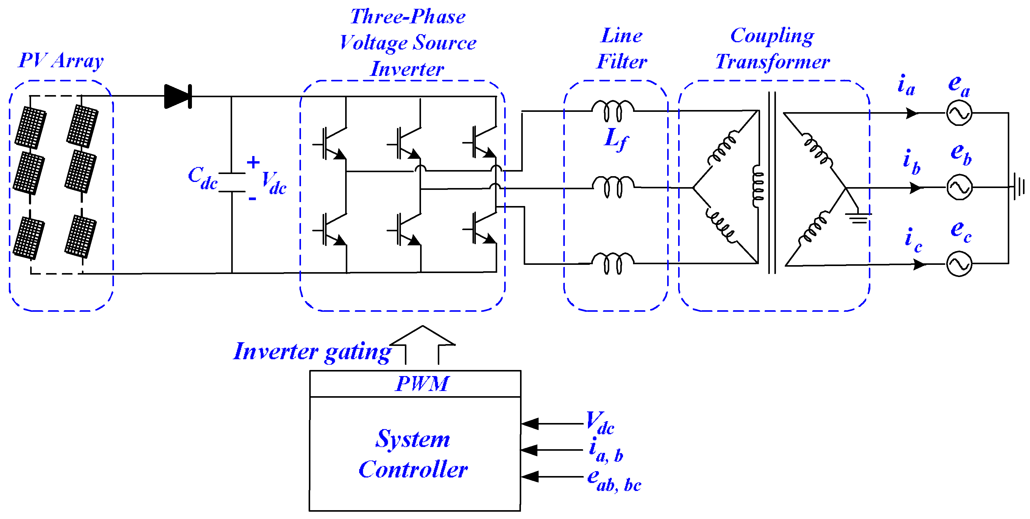
The overall system configuration of the proposed islanding detection method comprises of the PV array, voltage source inverter (VSI), a low-pass filter, and a step-up –Y transformer, as shown in Figure 7. The inverter circuit synchronizes the grid voltage with the inverter output current and its control unit is developed to implement the MPPT algorithm for extraction of the PV maximum power [53]. To reduce the high-frequency switching harmonics of the perturbation signals on the grid voltage, line filters are included.
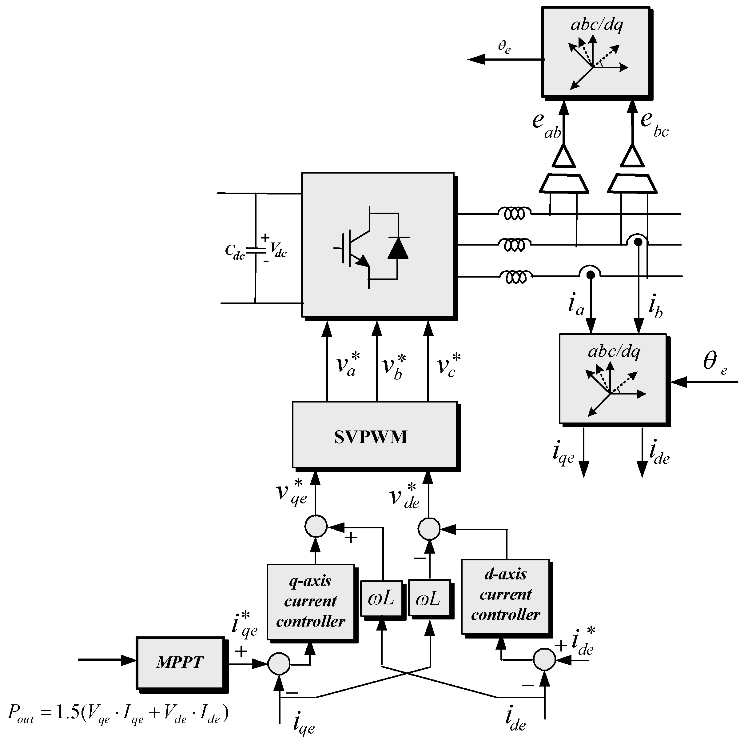
To achieve the MPPT and a unity output power factor, the abc voltages and currents are transformed into a rotating dq reference frame synchronized with the grid voltages. This reference frame is then used to represent the grid voltage and currents.
4. Results
To implement and verify the proposed islanding detection algorithm, a simulation of a three-phase PV system is simulated in the PSIM software. The electrical characteristics of a 50 Wp PV array to be used as the reference module for simulation are as follows: NS = 50, NP = 200, 17.4 (V) and 2.87 (A) are the voltage and current at maximum power. At the irradiation level of 1000 W/m2, the 60 strings of 50 modules PV generates 500 kWp.
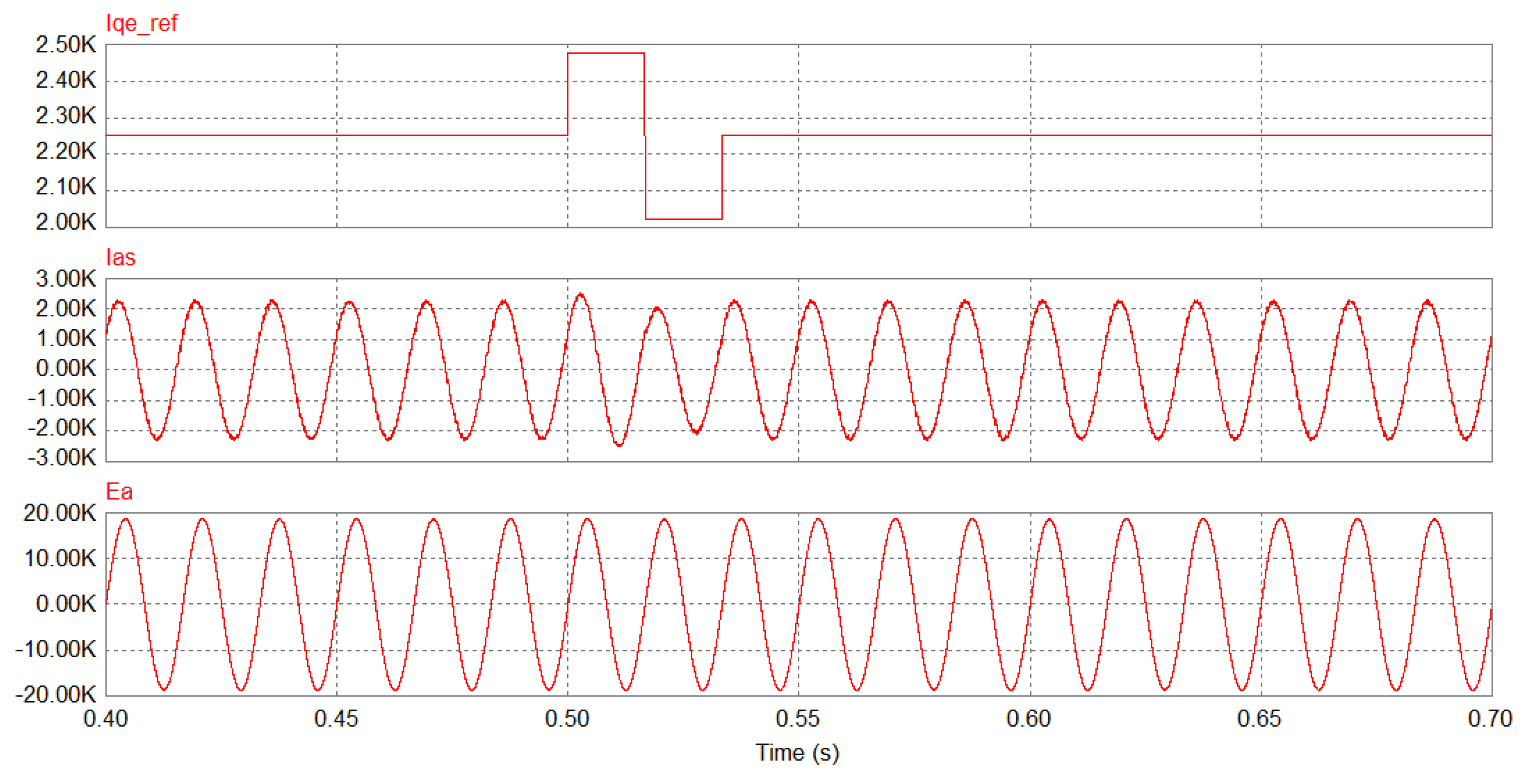
To continuously investigate the islanding condition, the inverter reference q-axis current is periodically disturbed. Figure 9 shows the perturbed q-axis current and its effect in varying the inverter phase current and output phase voltage. The value of the injected signal is ±10% to the rated q-axis current. The figure shows the disturbed inverter output current when the reference current is perturbed when the reference current is disturbed. The inverter current follows the reference current when its value is controlled by the nominal value. During the grid connection mode, Figure 10 shows the grid voltage, which remains constant, and the islanding factor that also remains zero. Figure 10 shows that the PV average output power remains constant even though it oscillates due to the variations in the q-axis current.
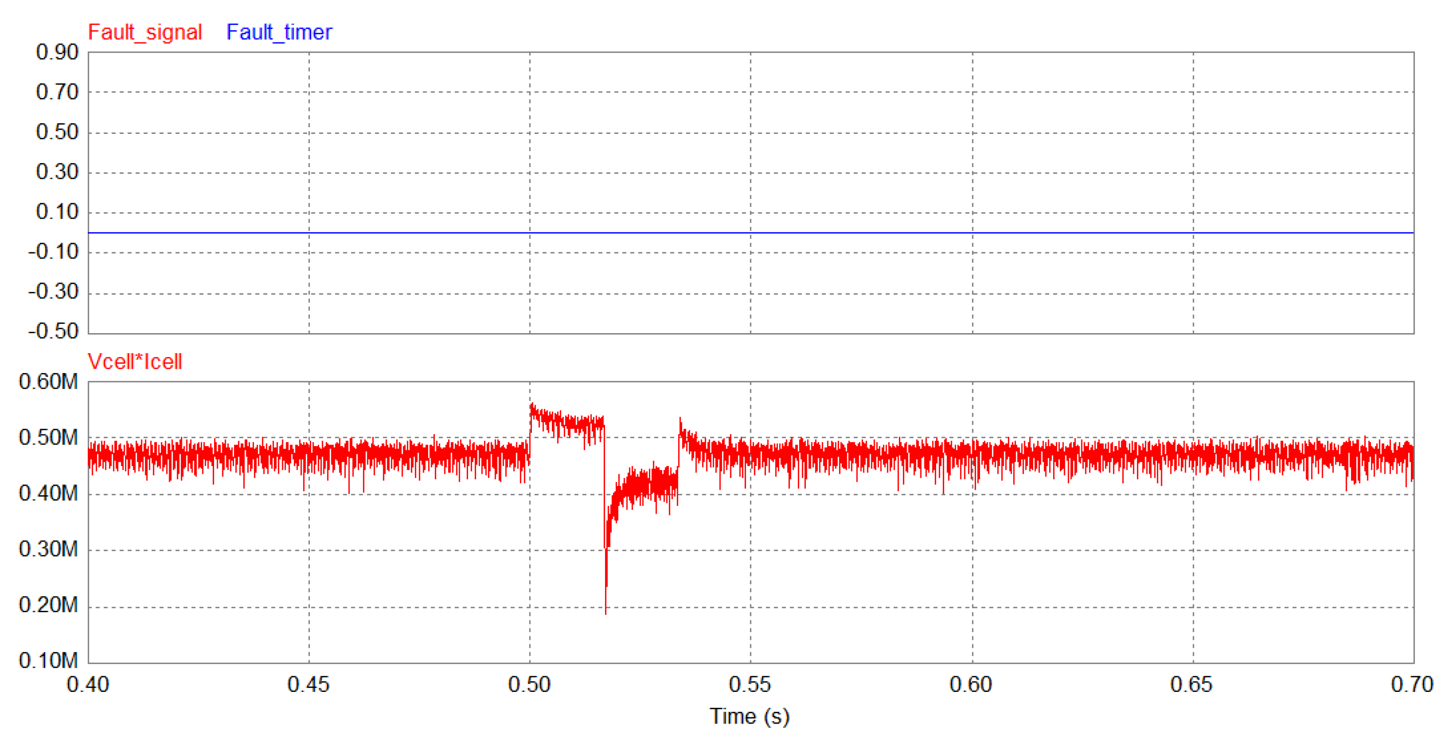
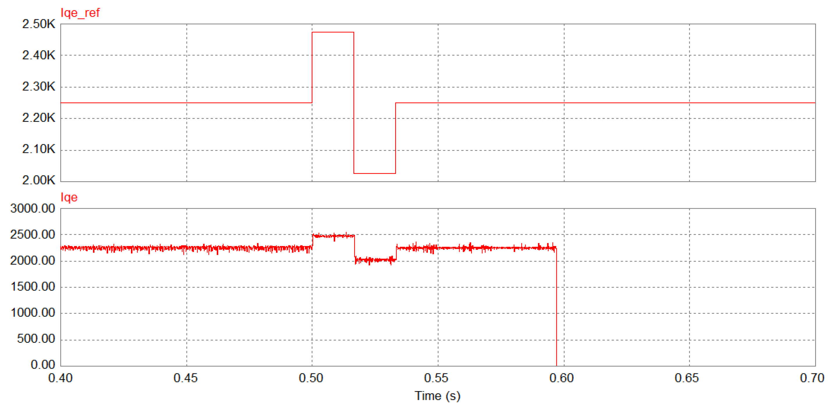
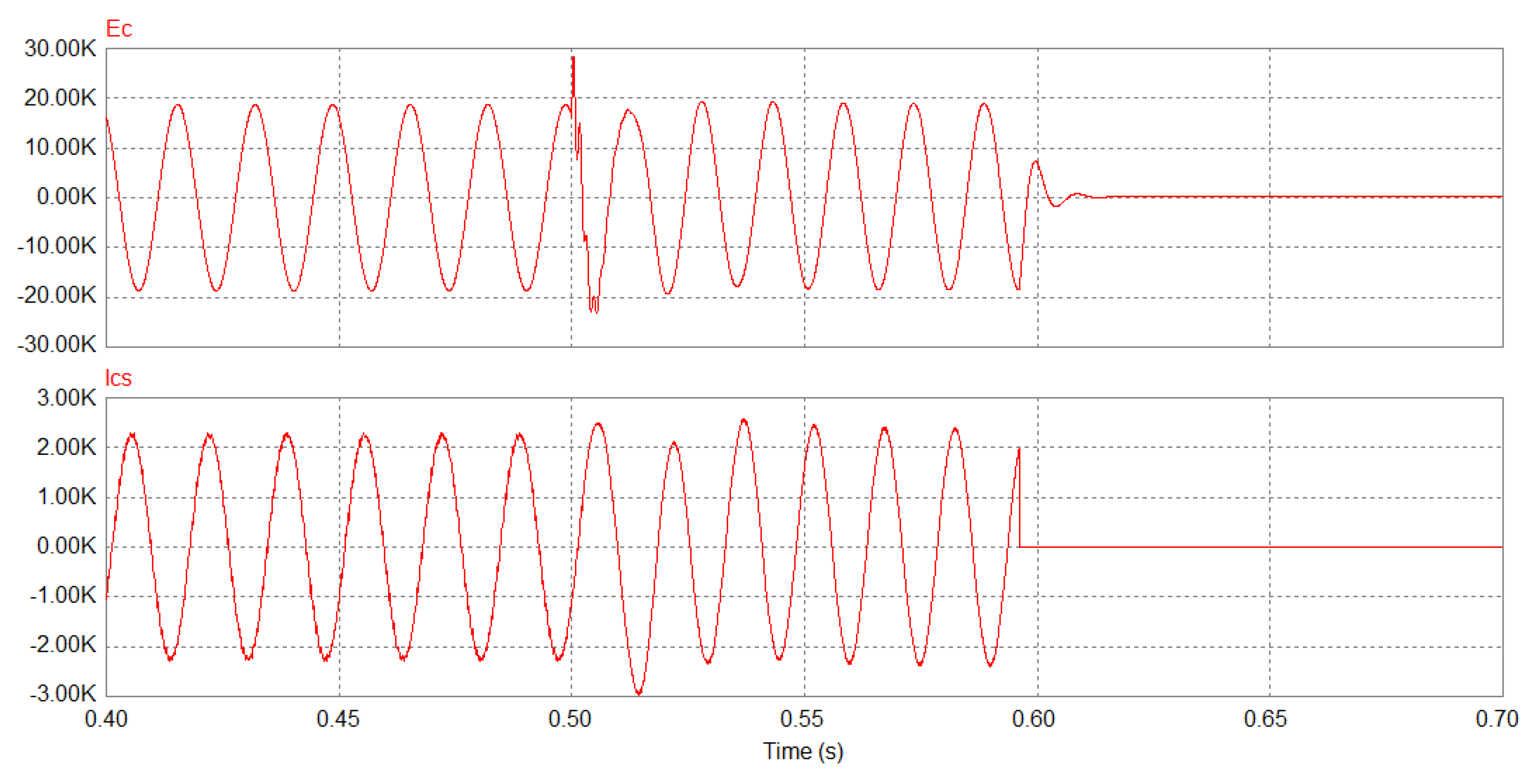
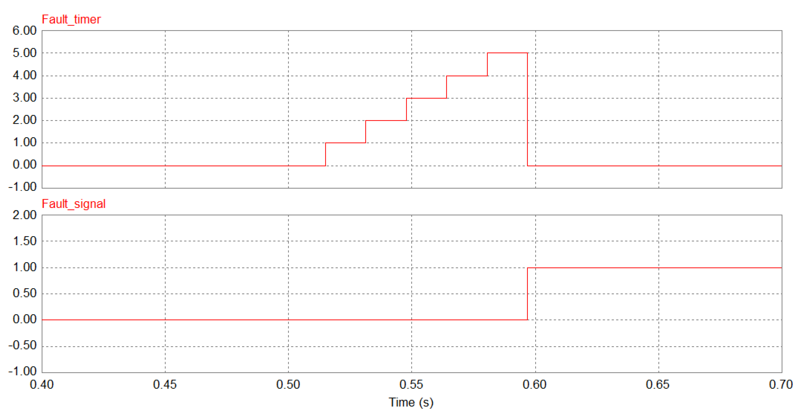
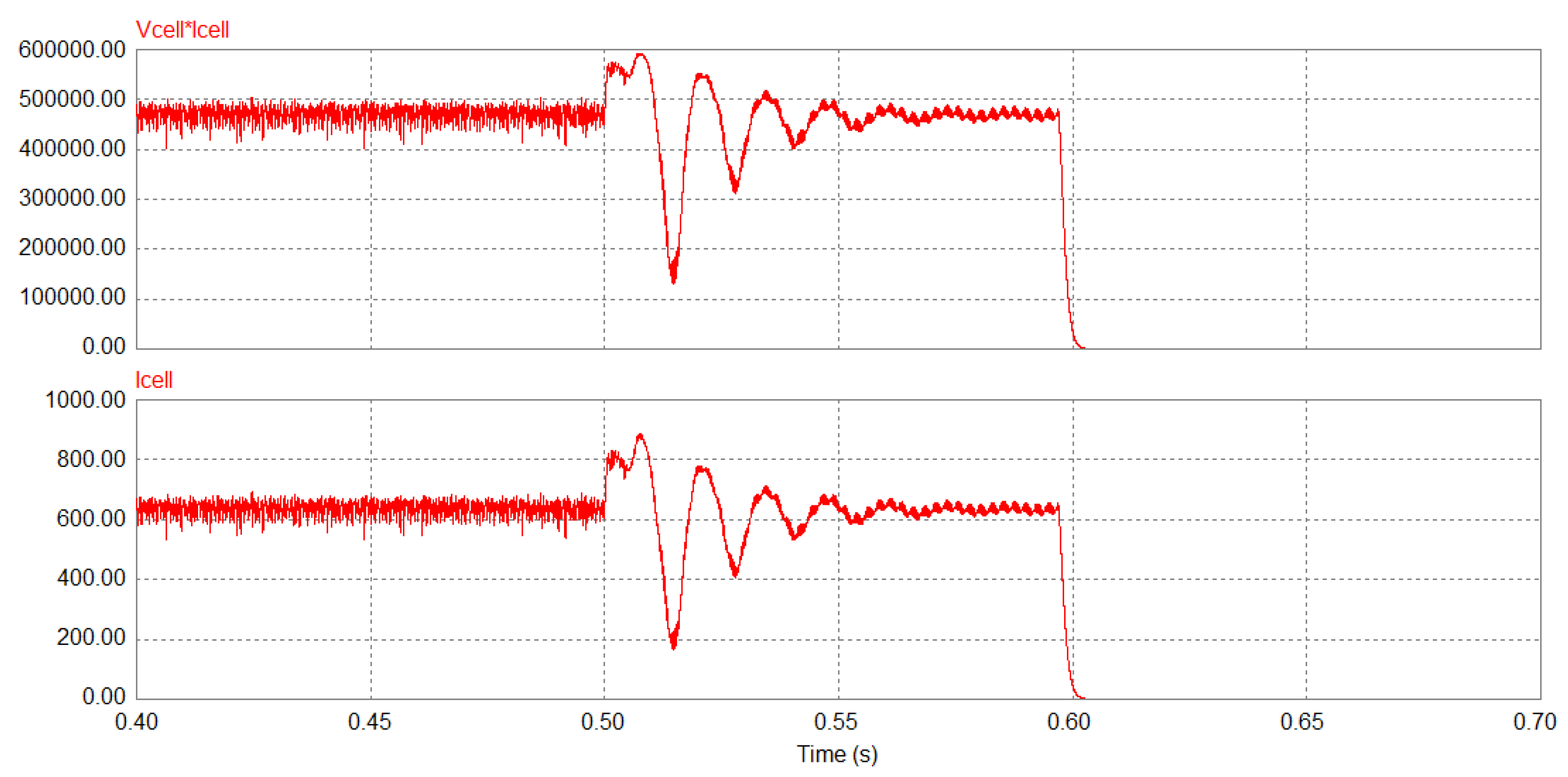
During the islanding mode, the perturbation of the q-axis current in Figure 11 deviates the output current and terminal voltage permanently from the nominal values, as shown in Figure 12. The islanding detection algorithm then starts to observe the voltage deviation incrementing the islanding factor to the limit value as shown in Figure 13. When the islanding factor reaches the limit, the inverter controller shuts it down and the PV output power falls to zero as shown in Figure 14.
To compare the performance proposed method with the other methods, it is found that the proposed method is faster than most of the active islanding detection methods such as the active impedance method, SFS, SMS, and AFD. However, this method has a larger NDZ than the other active methods. Due to the positive and negative perturbation sequence, this method has a better power quality. In addition, this method is more difficult to implement due to its complexity.
5. Conclusions
This paper introduced and analyzed several recent islanding detection methods for grid-connected PV systems. According to the discussion, the research trend of anti-islanding is mainly divided into passive methods, which are based on the measurement of system parameters such as voltage and frequency. Additionally, the active methods which are based on making disturbances on the inverter output voltage or current. As a conclusion of the comparison, the active methods provide faster response, high reliability, and a smaller power degradation. However, the active methods have a large NDZ and are difficult to implement as compared with the passive methods. The latter category is simple to implement and has no effect on the output power quality. However, the passive methods are not trusted for all load conditions as well as it is difficult to set the NDZ thresholds due to its large size. In addition, this paper proposes a new perturbation current signal based on the islanding detection of a three-phase PV. The injected signal results in a terminal voltage deviation when islanding occurs. However, the rigid grid voltage prevents the changes of the inverter output voltage magnitude during the connection mode. The proposed islanding detection algorithm was simulated under various load conditions and the simulation results show that the islanding detection time was about 0.1 s, which is very much faster than the required detection time of 2 s.
Author Contributions
A.G.A. and A.-R.A.-Q. suggested the research idea, collected the relevant papers, analyzed the data, performed simulations, and contributed in writing the manuscript. A.B.A. collected and analyzed the data and contributed in writing the manuscript.
Acknowledgments
The authors would like to thank the Deanship of Scientific Research, Majmaah University and his office for providing an opportunity and support to take up this research project. The Deanship of Research, Majmaah University (Contract No. 37/68).
Conflicts of Interest
The authors declare no conflicts of interest.
References
- Yang, F.; Xia, N.; Han, Q.-L. Event-Based Networked Islanding Detection for Distributed Solar PV Generation Systems. IEEE Trans. Ind. Inform. 2017, 13, 5045–5054. [Google Scholar] [CrossRef]
- Gungor, V.C.; Sahin, D.; Kocak, T.; Ergut, S. A survey on smart grid potential applications and communication requirements. IEEE Trans. Ind. Inform. 2013, 9, 28–42. [Google Scholar] [CrossRef]
- Mahat, P.; Chen, Z.; Jensen, B.B.; Bak, C.L. A simple adaptive overcurrent protection of distribution systemswith distributed generation. IEEE Trans. Smart Grid 2011, 2, 428–437. [Google Scholar] [CrossRef]
- Anonymous. IEEE Recommended Practice for Utility Interface of Photovoltaic (PV) Systems; IEEE STD 929-2000; IEEE Standards Department: Piscataway, NJ, USA, 2000. [Google Scholar]
- Anonymous. IEEE Standard for Interconnecting Distributed Resources with Electric Power Systems; IEEE STD 1547-2003; IEEE Standards Department: Piscataway, NJ, USA, 2003; pp. 1–16. [Google Scholar]
- Anonymous. IEEE Standard Conformance Test Procedures for Equipment Interconnecting Distributed Resources with Electric Power Systems; IEEE STD 1547; IEEE Standards Department: Piscataway, NJ, USA, 2005; pp. 1–54. [Google Scholar]
- Islam, S.; Woyte, A.; Belmans, R.; Heskes, P.; Rooij, P.M.; Hogedoorn, R. Cost effective second generation AC-modules: Development and testing aspects. Energy 2006, 31, 1897–1920. [Google Scholar] [CrossRef]
- Liu, N.; Aljankawey, A.; Diduch, C.; Chang, L.; Su, J. Passive islanding detection approach based on tracking the frequency-dependent impedance change. IEEE Trans. Power Deliv. 2015, 30, 2570–2580. [Google Scholar] [CrossRef]
- Merino, J.; Mendoza-Araya, P.; Venkataramanan, G.; Baysal, M. Islanding detection in microgrids using harmonic signatures. IEEE Trans. Power Deliv. 2015, 30, 2102–2109. [Google Scholar] [CrossRef]
- Ropp, M.E.; Begovic, M.; Rohatgi, A.; Kern, G.A.; Bonn, R.H.; Gonzalez, S. Determining the relative effectiveness of islanding detection methods using phase criteria and nondetection zones. IEEE Trans. Energy Convers. 2000, 15, 290–296. [Google Scholar] [CrossRef]
- Yu, B.; Abokhalil, A.G. Optimized AFD anti-islanding method for grid connected PV system. Int. Conf. Converg. Technol. 2013, 2, 1783–1784. [Google Scholar]
- Schweitzer, E. Synchrophasor-Based Power System Protection and Control Applications. In Proceedings of the 2010 Proceedings of the International Symposium Modern Electric Power Systems (MEPS), Wroclaw, Poland, 20–22 September 2010. [Google Scholar]
- Ebadollah, K.; Javad, S. Islanding detection method for photovoltaic distributed generation based on voltage drifting. IET Gener. Transm. Distrib. 2013, 7, 584–592. [Google Scholar]
- Jia, K.; Bi, T.; Liu, B.; Thomas, D.; Goodman, A. Advanced islanding detection utilized in distribution systems with DFIG. Int. J. Electr. Power Energy Syst. 2014, 63, 113–123. [Google Scholar] [CrossRef]
- Velasco, D. Review of anti-islanding techniques in distributed generator. Renew. Sustain. Energy Rev. 2010, 14, 1608–1614. [Google Scholar] [CrossRef]
- Ye, Z.H.; Kolwalkar, A.; Yu, Z.; Du, P.W. Evaluation of anti—Islanding schemes based on no detection zone concept. IEEE Trans. Power Electron. 2004, 19, 1171–1176. [Google Scholar] [CrossRef]
- Sareen, K.; Bhalja, B.R.; Maheshwari, R.P. Universal islanding detection technique based on rate of change of sequence components of currents for distributed generations. IET Renew. Power Gener. 2016, 10, 228–237. [Google Scholar] [CrossRef]
- Xu, W.; Zhang, G.; Li, C.; Wang, W.; Wang, G.; Kliber, J. A Power Line Signaling Based Technique for Anti-Islanding Protection of Distributed Generators—Part l: Scheme and Analysis. IEEE Trans. Power Deliv. 2007, 22, 1767–1772. [Google Scholar] [CrossRef]
- Mahat, P.; Chen, Z.; Bak-Jensen, B. Review of islanding detection methods for distribution generation. In Proceedings of the International Conference on Electric Utility Deregulation and Restructuring and Power Technologies (DRPT), Nanjing, China, 6–9 April 2008; pp. 2743–2748. [Google Scholar]
- Chandrakar, C.S.; Dewani, B.; Chandrakar, D. An assesment of distributed generationislanding detection methods. Int. J. Adv. Eng. Technol. 2012, 5, 218–226. [Google Scholar]
- Ropp, M.; Meandering, D.M.S. Discussion of a Power Line Carrier Communications-Based Anti-Islanding Scheme Using a Commercial Automatic Meter Reading System. In Proceedings of the 4th IEEE Conference on Photovoltaic Energy Conversion, Waikoloa, HI, USA, 7–12 May 2006; Volume 2, pp. 2351–2354. [Google Scholar]
- Yu, B.; Matsui, M.; Abo-Khalil, A.G.; Yu, G. A Correlation-Based Islanding Detection Method Using Current Disturbance for PV System. In Proceedings of the International Conference on Electrical Machines and Systems ICEMS, Tokyo, Japan, 15–18 November 2009. [Google Scholar]
- Moziza, C.J. Interconnection Protection of IPP Generators at Commercial/Industrial Facilities. IEEE Trans. Ind. Appl. 2001, 37, 681–688. [Google Scholar]
- Kunte, R.S.; Gao, W. Comparison and review of islanding detection techniques for distributed energy resources. In Proceedings of the 40th North American Power Symposium (NAPS’08), Calgary, AB, Canada, 28–30 September 2008. [Google Scholar]
- Abo-khalil, A.G.; Al-Qawasmi, A. A novel islanding detection method for three-phase photovoltaic generation systems. In Proceedings of the IEEE Applied Electrical Engineering and Computing Technologies (AEECT), Amman, Jordan, 3–5 December 2013; pp. 1–5. [Google Scholar]
- Robitaille, M.; Agbossou, K.; Doumbia, M.L. Modeling of an islanding protection method for a hybrid renewable distributed generator. Electr. Comput. Eng. 2005, 1, 1477–1481. [Google Scholar]
- Vatani, M.; Amrall, T.; Soltan, I. Comparative of Islanding Detection Passive methods for Distributed Generation Application. Int. J. Innov. Sci. Res. 2014, 8, 234–241. [Google Scholar]
- Yu, B.; Abo-Khalil, A.G.; Matsui, M.; Yu, G. Support Vector Regression Based Maximum Power Point Tracking for PV Grid-Connected System. In Proceedings of the 2009 34th IEEE Photovoltaic Specialists Conference (PVSC), Philadelphia, PA, USA, 7–12 June 2009. [Google Scholar]
- Wen, B.; Boroyevich, D.; Burgos, R.; Shen, Z.; Mattavelli, P. Impedance-based analysis of active frequency drift islanding detection for grid-tied inverter system. IEEE Trans. Ind. Appl. 2016, 52, 332–341. [Google Scholar] [CrossRef]
- Kim, J.; Kim, J.; Ji, Y.; Jung, Y.; Won, C. An Islanding Detection method for a Grid-connected System Based on the Goertzel Algorithm. IEEE Trans. Power Electron. 2011, 26, 1049–1055. [Google Scholar] [CrossRef]
- Mahat, P.; Chen, Z.; Jensen, B. Review on islanding operation of distribution system with distributed generation. In Proceedings of the Power Energy Society General Meeting, San Diego, CA, USA, 24–29 July 2011; pp. 1–8. [Google Scholar]
- Boonyapakdee, N.; Sapaklom, T.; Konghirum, M. An Implement of Improved Combine Active Islanding Detection Method on frequency and phase perturbations. In Proceedings of the IEEE International Conference on Electrical Machines and System, Busan, Korea, 26–29 October 2013; pp. 208–213. [Google Scholar]
- Liu, F.; Kang, Y.; Zhang, Y.; Duan, S.; Lin, X. Improved SMS Islanding Detection Method for Grid-Connected Converters. IET Renew. Power Gener. 2010, 4, 36–42. [Google Scholar] [CrossRef]
- Yafaoui, A.; Wu, B.; Kouro, S. Improved active frequency drift anti-islanding detection method for grid connected photovoltaic systems. IEEE Trans. Power Electron. 2012, 27, 2367–2375. [Google Scholar] [CrossRef]
- El-Moubarak, M.; Hassan, M.; Faza, A. Performance of three islanding detection methods for grid-tied multi-inverters. In Proceedings of the IEEE 15th International Conference Environment and Electrical Engineering (EEEIC), Rome, Italy, 10–13 June 2015; pp. 1999–2004. [Google Scholar]
- Liu, F.; Kang, Y.; Duan, S. Analysis and Optimization of Active Frequency Drift Islanding Detection Method. In Proceedings of the IEEE Applied Power Electronics Conference, Anaheim, CA, USA, 25 February–1 March 2007; pp. 1379–1384. [Google Scholar]
- Raghav, L.P.; Sandhya, T. An Active Frequency Drift Method for an Islanding Detection of Grid Connected Microturbine Generation System. Available online: https://www.researchgate.net/profile/Phani_Raghav_Lolla/publication/264534888_An_Active_Frequency_Drift_method_for_Islanding_Detection_of_Grid_connected_Microturbine_Generation_system/links/53e312670cf275a5fdda76da/An-Active-Frequency-Drift-method-for-Islanding-Detection-of-Grid-connected-Microturbine-Generation-system.pdf (accessed on 23 May 2018).
- Yafaoui, A.; Wu, B.; Kouro, S. Improved Active Frequency Drift Anti-islanding Method with Lower Total Harmonic Distortion. In Proceedings of the 36th Annual Conference on IEEE Industrial Electronics Society (IECON 2010), Denver, CO, USA, 15–19 September 2010; pp. 3216–3221. [Google Scholar]
- Huang, W.; Zheng, T.; Yuan, F.; Wang, Z.; Xu, S. Analysis of the NDZ Formulation Theory of Active Frequency Shift Islanding Detection Method for Grid Connected PV System. In Proceedings of the IEEE Power and Energy Engineering Conference (APPEEC), Hong Kong, China, 8–11 December 2013; pp. 1–5. [Google Scholar]
- Kotsopoulos, A.; Duarte, J.; Hendrix, M.; Heskes, P. Islanding behaviour of grid-connected PV inverters operating under different control schemes. In Proceedings of the Power Electronics Specialist Conference (PESC’02), Cairns, Australia, 23–27 June 2002; pp. 1506–1511. [Google Scholar]
- Roop, M.; Ginn, J.; Stevens, J.; Bower, W.; Gonzales, W.S. Simulation and experimental study of the impedance detection anti-islanding method in the single-inverter case. In Proceedings of the Conference Record of the 2006 IEEE 4th World Conference on Photovoltaic Energy Conversion, Waikoloa, HI, USA, 7–12 May 2006; Volume 2, pp. 2379–2382. [Google Scholar]
- Yoo, C.; Jang, D.; Han, S.; Oh, D.; Hong, S. A new phase drift anti-islanding method for grid-connected inverter system. In Proceedings of the Eighth International Conference on Power Electronics—ECCE Asia, Jeju, Korea, 30 May–3 June 2011; pp. 902–906. [Google Scholar]
- Teoh, W.; Tan, C. An overview of islanding detection methods in photovoltaic systems. World Acad. Sci. Eng. Technol. 2011, 58, 674–682. [Google Scholar]
- Zeineldin, H.; Conti, S. Sandia frequency shift parameter selection for multi-inverter systems to eliminate non-detection zone. IET Renew. Power Gener. 2011, 5, 175–183. [Google Scholar] [CrossRef]
- Vahedi, H.; Karrari, M. Adaptive Fuzzy Sandia Frequency Shift Method for Islanding Protection of Inverter Based Distributed Generation. IEEE Tran. Power Deliv. 2013, 28, 84–92. [Google Scholar] [CrossRef]
- Du, P.; Ye, Z.; Aponte, E.; Keith, J.; Fan, L. Positive-Feedback-Based Active Anti-Islanding Schemes for Inverter-Based Distributed Generators: Basic Principle, Design Guideline and Performance Analysis. IEEE Trans. Power Electron. 2010, 25, 2941–2948. [Google Scholar]
- Wang, X.; Freitas, W.; Xu, W. Dynamic Non-Detection Zones of Positive Feedback Anti-Islanding Methods for Inverter-Based Distributed Generators. IEEE Trans. Power Deliv. 2011, 26, 1145–1155. [Google Scholar] [CrossRef]
- Zeineldin, H.; Salama, M. Impact of load frequency dependence on the NDZ and performance of the SFS islanding detection method. IEEE Trans. Ind. Electron. 2011, 58, 139–146. [Google Scholar] [CrossRef]
- Bahrani, B.; Karimi, H.; Iravani, R. Nondetection zone assessment of an active islanding detection method and its experimental evaluation. IEEE Trans. Power Deliv. 2011, 26, 517–525. [Google Scholar] [CrossRef]
- Rani, B.; Srikanth, M.; Ilango, G.; Nagamani, C. An active islanding detection technique for current controlled inverter. Renew. Energy 2013, 51, 189–196. [Google Scholar] [CrossRef]
- Álvarez, B.; Rivera, O. Survey of distributed generation islanding detection methods. IEEE Latin Am. Trans. 2010, 8, 565–570. [Google Scholar] [CrossRef]
- Abo-Khalil, A.G. A New Wind Turbine Simulator using a Squirrel-Cage Motor for Wind Power Generation Systems. In Proceedings of the Power Electronics and Drive Systems Conference (PEDS), Singapore, 5–8 December 2011. [Google Scholar]
- Abo-Khalil, A.G. Model-based optimal efficiency control of induction generators for wind power systems. In Proceedings of the IEEE International Conference on Industrial Technology (ICIT), Auburn, AL, USA, 14–16 March 2011; pp. 191–197. [Google Scholar]
Figure 1.
The anti-islanding methods classification.

Figure 2.
The test circuit for the islanding detection function in a photovoltaic (PV) power inverter.
Figure 2.
The test circuit for the islanding detection function in a photovoltaic (PV) power inverter.

Figure 3.
An example of a non-detectable zone (NDZ).

Figure 4.
The diagram showing the phase jump due to islanding.

Figure 5.
The operational waveform of active frequency drift (AFD) method.

Figure 6.
The operational waveforms of reference q-axis current, voltage value, islanding factor, and islanding confirmation.
Figure 6.
The operational waveforms of reference q-axis current, voltage value, islanding factor, and islanding confirmation.

Figure 7.
The power circuit for a PV system.

Figure 8.
The control circuit for the PV system.

Figure 9.
The q-axis current, phase current, and phase voltage without islanding.

Figure 10.
The fault timer and PV power without islanding.

Figure 11.
The perturbed q-axis reference and actual current.

Figure 12.
The instantaneous waveforms of grid voltages and currents.

Figure 13.
The islanding factor and islanding confirmation.

Figure 14.
The PV power and current before and after islanding.

© 2018 by the authors. Licensee MDPI, Basel, Switzerland. This article is an open access article distributed under the terms and conditions of the Creative Commons Attribution (CC BY) license (http://creativecommons.org/licenses/by/4.0/).
Share and Cite
MDPI and ACS Style
Abokhalil, A.G.; Awan, A.B.; Al-Qawasmi, A.-R. Comparative Study of Passive and Active Islanding Detection Methods for PV Grid-Connected Systems. Sustainability 2018, 10, 1798. https://doi.org/10.3390/su10061798
AMA Style
Abokhalil AG, Awan AB, Al-Qawasmi A-R. Comparative Study of Passive and Active Islanding Detection Methods for PV Grid-Connected Systems. Sustainability. 2018; 10(6):1798. https://doi.org/10.3390/su10061798
Chicago/Turabian StyleAbokhalil, Ahmed G., Ahmed Bilal Awan, and Abdel-Rahman Al-Qawasmi. 2018. "Comparative Study of Passive and Active Islanding Detection Methods for PV Grid-Connected Systems" Sustainability 10, no. 6: 1798. https://doi.org/10.3390/su10061798
Note that from the first issue of 2016, this journal uses article numbers instead of page numbers. See further details here.