Computer Vision-Based Bridge Displacement Measurements Using Rotation-Invariant Image Processing Technique


Department of Civil and Environmental Engineering, Hanyang University, 222 Wangsimni-ro, Seongdong-gu, Seoul 04763, Korea
*
Author to whom correspondence should be addressed.
Sustainability 2018, 10(6), 1785; https://doi.org/10.3390/su10061785
Submission received: 20 April 2018
/
Revised: 23 May 2018
/
Accepted: 28 May 2018
/
Published: 29 May 2018
(This article belongs to the Special Issue Sustainability in Construction Engineering)
Abstract
:Bridges are exposed to various kinds of external loads, including vehicle and hurricanes, during their life cycle. These loads cause structural damage, which may lead to bridge collapse. To ensure bridge safety, it is essential to periodically inspect the physical and functional conditions of bridges. The displacement responses of a bridge have significance in determining the structural behaviors and assessing their safety. In recent years, many researchers have been studying bridge displacement measurements using image processing technologies. Image-processing-based displacement measurements using a computer analysis system can quickly assess bridge conditions and, thus, can be used to enhance the reliability of bridges with high accuracy. This paper presents a method based on multiple-image processing bridge displacement measurements that includes enhanced robustness to image rotation. This study applies template matching and a homography matrix to measure the displacement that works well regardless of the angle between the smartphone camera and the target.
1. Introduction
In modern society, bridges serve as the backbone of a nation’s economy as they connect separated regions and provide effective means of transportation to accommodate the needs of populations experiencing explosive growth. However, severe weather can badly damage bridge structures, reducing their life and safety. Therefore, systematic inspections and maintenance must be performed to maintain the optimum conditions of bridges. A bridge’s displacement responses provide valuable information for structural analysis to assess bridge safety [1,2] and performance. Thus, the monitoring of displacement characteristics is a critical issue for the safety and maintenance of bridges. Displacement response measurements in bridges are normally done using high precision sensors, such as linear-variable differential transformers (LVDTs) [3], accelerometers [4], global positioning systems (GPSs). However, such conventional methods have limitations [5,6,7]. For instance, an LVDT or accelerometer must be installed with additional equipment, such as data loggers (including cables and power supply equipment), which can introduce inconvenience and extra monitoring-cost for large-scale bridges and structures. Moreover, bridge monitoring based on acceleration measurements is relatively an effortless approach, as it determines the displacement by simply double integrating the acceleration values, however, the biased initial conditions may create unstable results [8]. On the other hand, the GPS-based method has low precision of vertical displacement measurements [9]. The computer vision-based techniques offer significant advantages over conventional sensing systems for measuring structural responses such as (i) computer vision-based techniques can measure displacements of multiple points from a motion image captured by a single camera; (ii) the computer vision-based technique does not require physical access to the structures, as the vision sensors (such as cameras) can be setup at a remote location and can easily alter the measurement points; (iii) computer vision-based techniques can be placed hundreds of meters away from the bridge (when using a zoom high resolution lens) and still achieve satisfactory measurement accuracy. Thus, the computer vision method can effectively reduce time and cost compared to previous sensor-based methods. In past structural inspections, computer vision technology was often used to detect cracks [10]. Crack inspection research focuses primarily on techniques that accurately analyze the length, width, and depth of cracks [11]. Recently, computer vision technique has gradually expanded in the field of dynamic response measurements for various structures, including buildings and bridges [12]. For example, Stephen et al. [13] presented an image-tracking system to measure bridge–deck displacement. This image tracking system was successfully applied at Humber Bridge in the UK. Olaszek [14] utilized photogrammetric principle and introduced a scheme to measure displacement and dynamic characteristics of bridges. Guo [15] proposed computer vision technology including a Lucas–Kanade template tracking algorithm to measure the dynamic displacement of large-scale structures. Shan et al. [16] proposed bridge deflection monitoring technique based on Zhang’s [17] camera calibration method. Feng and Feng [18,19] proposed structural modal property identification method utilizing computer vision technique. Similarly, Yoon et al. [20] proposed a computer vision-based method using consumer-grade cameras to identify the dynamic characteristic of structures.
Computer vision-based systems for structural displacement measurements mainly rely on template matching [21]. Template matching approach is an image processing technique to determine the locations of an image matching a predefined template image. To match image, the template image is compared against the source image by moving it one pixel at a time. At each location, a correlation-coefficient is computed indicating the similarity between template image and a specific area of the source image. As all the possible locations of template image are considered and compared with source image, therefore, the area with highest correlation-coefficient becomes the target position. The displacement measurement using the digital image correlation (DIC) approach is a computer vision technology that employs a digital camera and image processing for accurate measurements of changes in images. The use of the DIC method to measure displacements of objects was initially proposed by researchers at the University of South Carolina [22,23,24]. The DIC technique has shown wide scale powerful and flexible applications in the field of experimental solid mechanics, particularly for measuring the surface deformations [25]. Moreover, it has been studied and applied by several researchers for structural displacement measurement [5,26,27]. In recent years, the displacement measurement method using DIC has been realized as a simple system because it is an image-processing technique correlating the original image and deformation image. Therefore, it has shown high applicability to the various devices. In object tracking, DIC is not an ideal technique as it can be easily affected by image scale and rotation [28]. In order to overcome the limitations of template-based matching using DIC technique, Jeong et al. [29] proposed a pan-tilt-zoom (PTZ) camera-based computer vision system using a sum of squared differences (SSD) and homography-matrix [30], this system is capable of expanded measurable range in monitoring structural displacement. Till present, several correlation-coefficient functions have been introduced including normalized cross-correlation (NCC), sum of absolute differences (SAD), sum of squared differences (SSD), zero-mean normalized cross-correlation (ZNCC), zero-mean sum of absolute differences (ZSAD), zero-mean sum of squared differences (ZSSD), optimized sum of absolute difference (OSAD), and optimized sum of squared difference (OSSD) [31,32]. Among these, NCC, SAD, SSD, and ZNCC have been widely adopted in template matching from the field of objects tracking [32]. The SSD is a popular method for many applications, including template-based matching, due to its efficient computational schemes. However, it is sensitive to illumination changes [33]. On the other hand, NCC has robustness advantages against illumination change. In addition to, NCC is a very simple approach for determining multiple patterns from a source image. Thus, the NCC function is mainly used to measure the displacement of the structure in the civil engineering [34,35].
Present study introduces a computer vision method for bridge displacement measurement, enabled by the robust template matching supported by homography-matrix and NCC function. Additionally, for motion image capture, smartphone camera was used instead of the conventional commercial-scale expensive cameras. The adoption of smartphone would allow the quick safety inspection of bridge because of being cost-effective, mobile, and ease of installation.
2. Literature Review
Jauregui et al. [36] successfully measured the vertical deflections of bridge structures by implementing close-range terrestrial photogrammetry approach. For highly accurate displacement measurements, a sub-pixel edge detection algorithm was introduced by Poudel et al. [37]. Fu and Moosa [38] utilized high resolution CCD camera to develop a cost-effective and efficient technique for the measurement of displacement in civil structures. A vision-based system for the accurate monitoring of absolute displacement was introduced by Wahbeh et al. [39]. The architecture of this system is simply comprised of a LED, a camera, and a computer. Through experiments on the Vincent Thomas Bridge in California, researchers demonstrated the feasibility of this approach for measuring bridge displacement. Kohut et al. [40] conducted a comparative research on radar interferometry and vision-based methods to measure the displacements in civil structures. They demonstrated the precision of vision-based techniques by implementing them on a steel bridge; moreover, they accurately determined the bridge displacement. Lee and Shinozuka [5,41,42] developed an image processing system which is digital enough to monitor and measure the dynamic displacements of flexible bridges in real-time. This system was also shown to have the ability to assess the load carrying capacity of a steel girder bridge located in Korea. Fukuda et al. [6] introduced a vision-based displacement measurement system that utilizes a low-cost digital camcorder and a PC. Similarly, Choi et al. [43] presented a structural dynamic displacement system that could perform multi-measurements using an economical handheld digital camcorder. Ho et al. [44] developed a synchronous vision system implementing an image-processing approach to measure the dynamic displacement of civil infrastructures. This system can simultaneously support several camcorders for real-time multipoint displacement measurements. Tian and Pan [45] proposed a vision-based displacement measurement device using LED targets for real-time measurements of bridge deflection. Yoneyama et al. [27] obtained bridge deflection measurements using a digital image correlation method for bridge load tests. Busca et al. [46] combined pattern matching, digital image correlation, and edge detection and developed a vision-based technique for the monitoring of dynamic response of bridge.
A remote vision-sensor system in combination with advance template matching, to measure the displacement in civil infrastructures was proposed by Feng et al. [47]. Ribeiro et al. [7] introduced a video system based on the RANdom SAmple Consensus (RANSAC) algorithm. This algorithm accurately determines the dynamic displacement of railroad bridges. Feng et al. [48] developed a markerless vision-based system using an advanced orientation code-matching (OCM) algorithm to measure the dynamic displacement of bridges. Jeon et al. [49] presented a paired visual servoing system to measure the six degrees of freedom (6-DOF) displacement of high-rise buildings and long-span bridges. Similarly, Park et al. [50] measured the three-dimensional displacement associated with structures with the utilization of a capture system. This system is capable of high sample rate for the accurate measurement of displacement. Chang and Xiao [51] used a single-camera based video-grammetric approach to measure both three-dimensional translation in concurrence with the rotation of the planer marker installed on the structure. Ji and Chang [52] proposed a novel vision-based method that used an optical flow technique to eliminate the use of a marker. This system used a camcorder to measure the vibrational responses of a small pedestrian bridge. In another study, Ji and Chang [53] presented a markerless stereo vision technique to monitor the dynamic responses of line-like elements, such as cables, in both spatial and temporal domains. Kim and Kim [54] proposed a markerless vision technique that utilized digital image correlation obtained from a portable and digital camcorder to measure hanger cable tensions of a suspension bridge. Kim [55] proposed a multi-template matching method that rectifies the errors occurring during marker recognition as noise in after-images. This noise is usually caused by the camera shaking and by high-speed motion of the cables. A digital photogrammetry method [56] using multiple camcorders to measure the synchronized ambient vibrations at various points of a stay cable bridge has been proposed, this approach effectively identifies the mode shapes ratios. For the quick inspection of the cable supported bridge, Zhao et al. [57] conducted an experiment on the feasibility and utilization of the computer vision-based cable force estimation method using a smartphone camera. They used a D-viewer and iPhone 6 to measure the vibration characteristics of the cable. Based on a previous study [57], Zhao et al. [58] proposed a computer vision-based approach for identifying the natural frequencies of cable and estimating cable force using a smartphone camera.
3. Computer Vision-Based Bridge Displacement Measurement
3.1. Overview
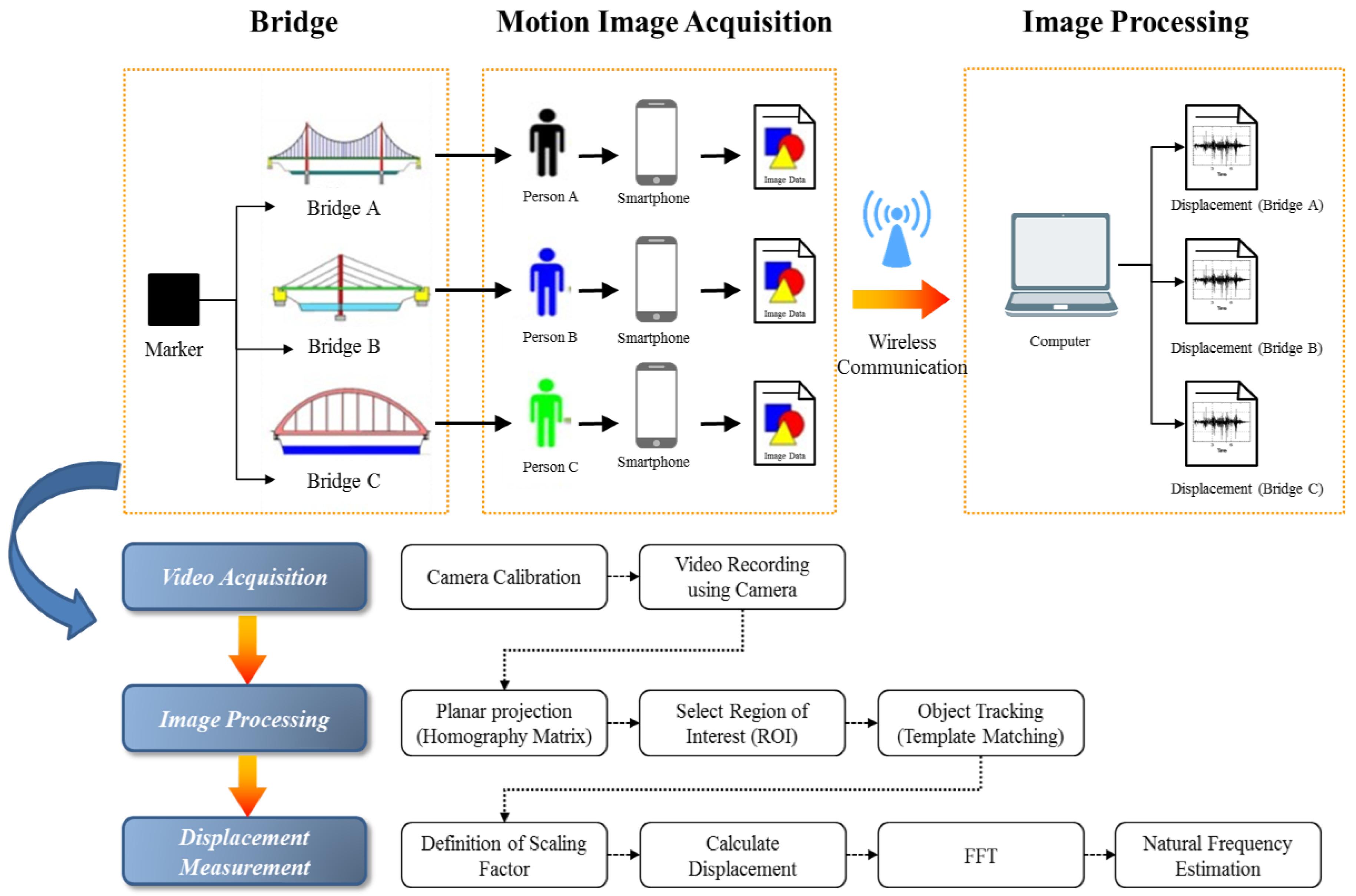
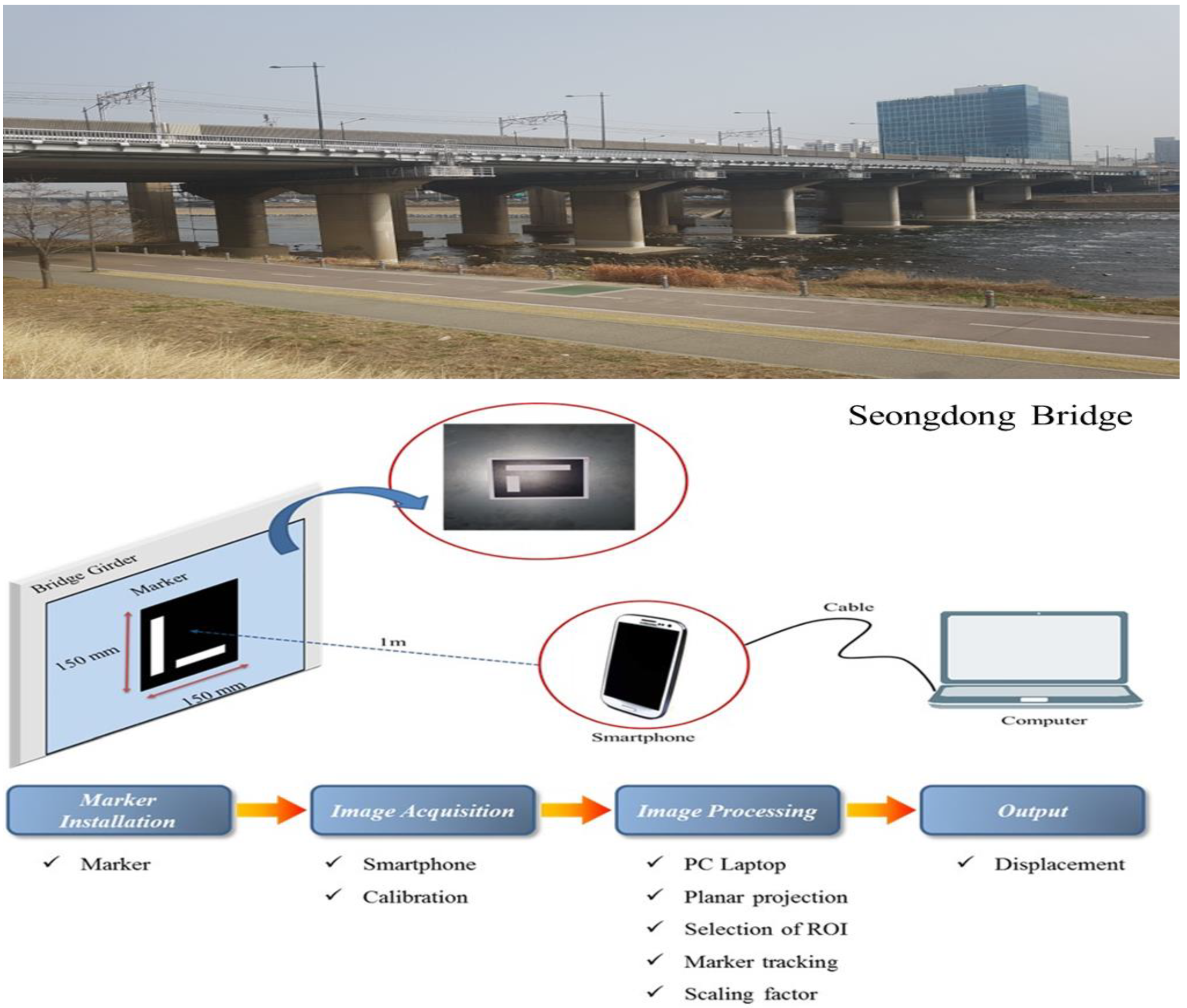
Figure 1 shows an overview of the proposed computer vision-based displacement measurement methodology. This system consists of a marker, a smartphone camera, and a computer installed with an image processing software. The connection between the smartphone and the computer is conducted by a wireless communication or cable. The proposed computer vision-based displacement measurement method is composed of three main phases: (1) motion image acquisition; (2) image processing for object tracking; and (3) calculation of bridge displacement. The smartphone camera is fixed on a tripod and is located at about 1 m away from the marker. Installation of smartphone camera and its focusing is time-effective, as it takes a few minutes. The smartphone camera gets the motion images of the marker for displacement measurement, and computer analyzes the marker’s movement and bridge displacement through image processing software. This image processing relies on the homographic matrix for the planar projections of the captured motion images, and template-based matching algorithms using on the NCC function for object tracking.
3.2. Camera Calibration
Accurate calculation of bridge displacement based on measurements from motion images requires the correction of camera distortion. Generally, camera calibration is the most crucial stage for a vision-based system. Because the proposed system relies on motion images from a camera to determine displacement, the accuracy is highly influence by the precision calibration of the camera. In this regard, to eliminate distortion from the camera lens, Zhang [17] proposed a camera calibration algorithm based on the 2D planar pattern. In the present study, the inherent and extraneous characteristics of camera, and distortion coefficient of camera lenses were estimated using Zhang’s calibration algorithm (for more details see [17]).
3.3. Template-Based Matching Method
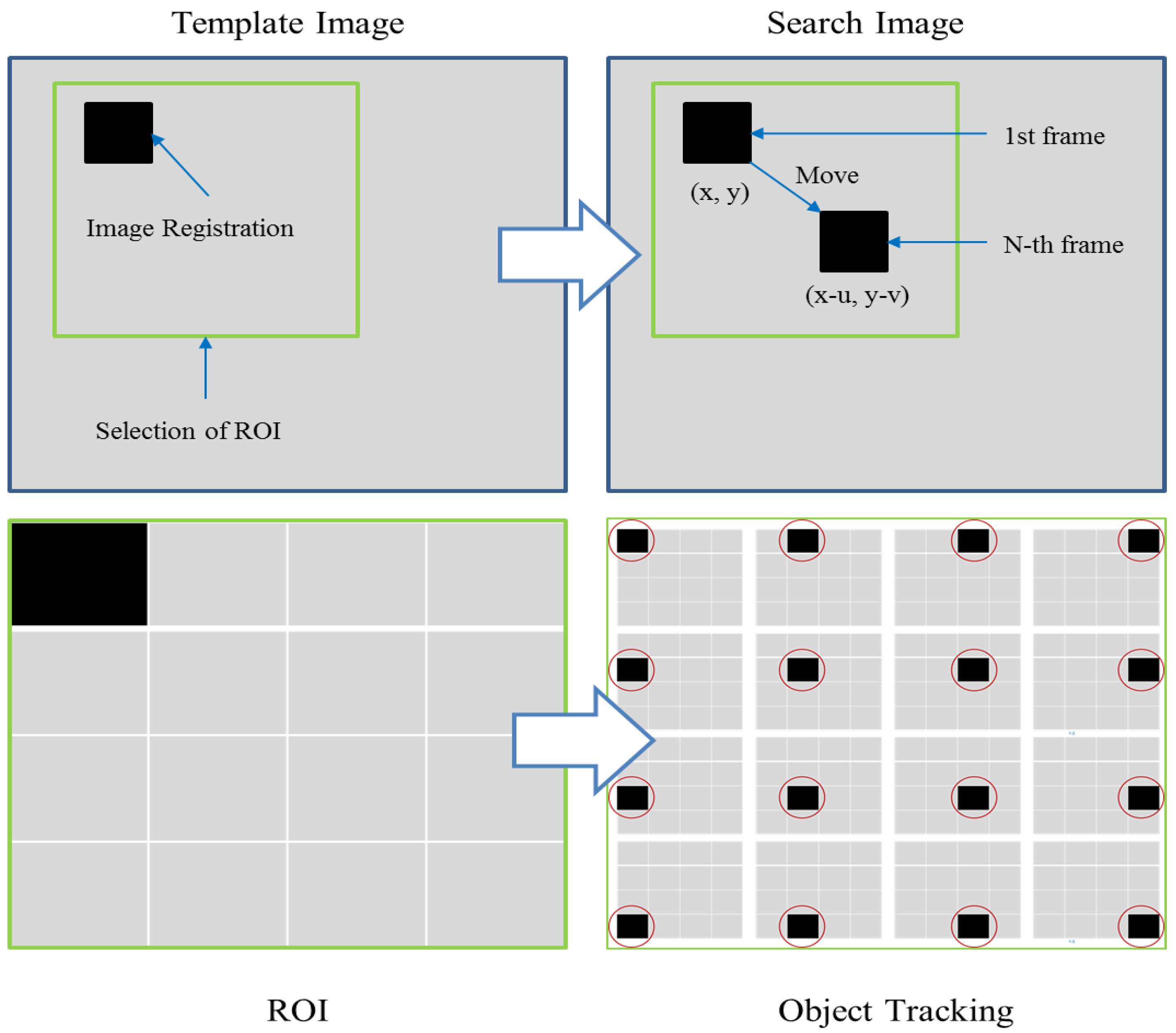
Among the object tracking methods, the template-based matching technique is commonly applied specifically for the measurement of structures. The template-based matching technique is normally implemented by first registering a part of the search image to use as a template image (such as marker). Because the template image is registered, an object can be found in the search image using NCC [28] function. The NCC is a sub-class of DIC is one of the most promising approach to analyze the resemblance of two individual images base on their cross-correlation. The NCC coefficient is defined by Equation (1). The basic concept of the template-matching technique is shown in Figure 2.
- = correlation coefficient
- = intensity value of search image at point
- = mean value of within the region of the template
- = mean value of the template
3.4. Homography-Matrix
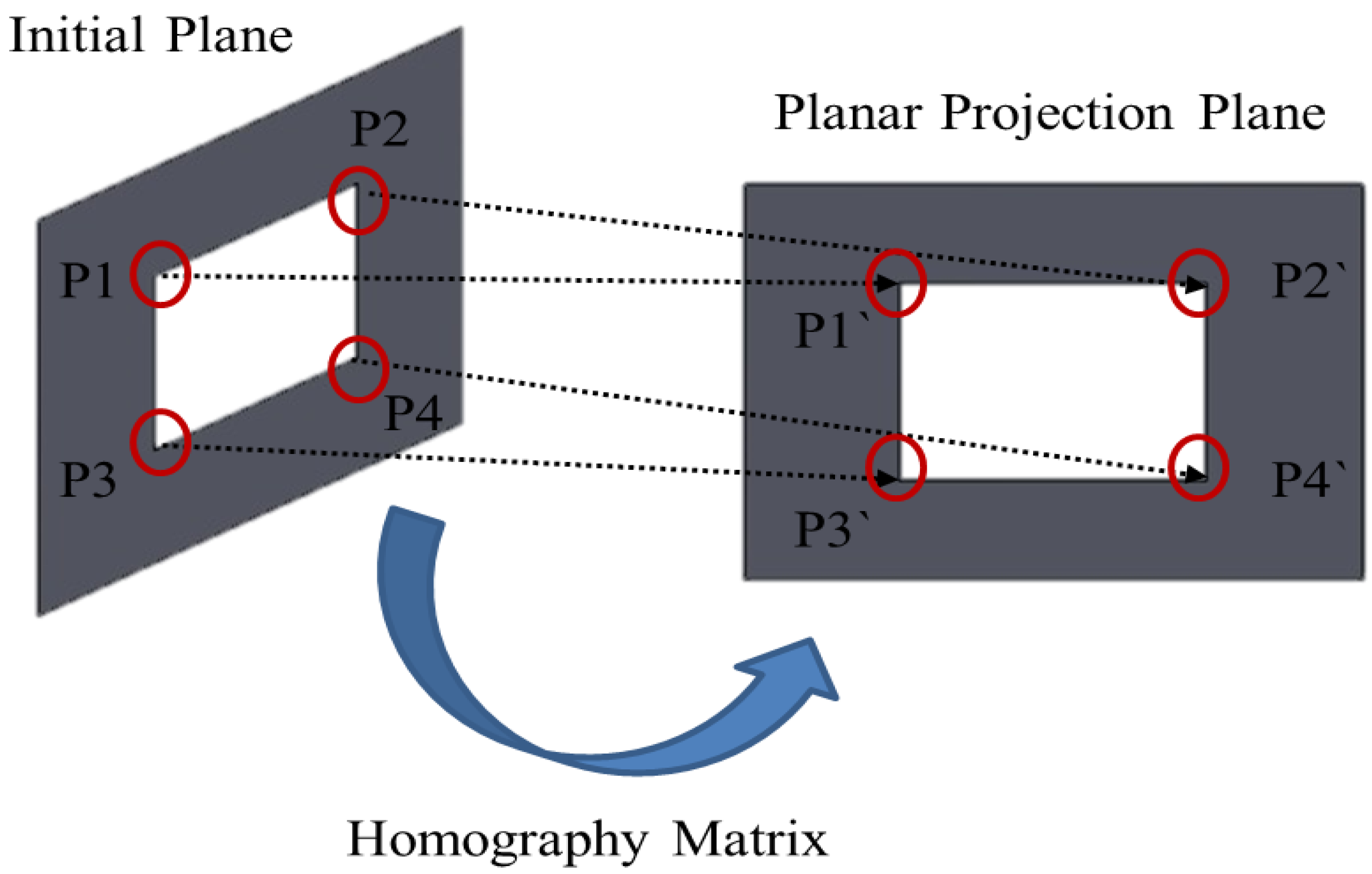
For precise displacement measurements, an image transformation function should be applied to eliminate geometric distortions. Therefore, the present method includes the homography approach [30] to eliminate the geometric distortions of image scale and rotation. Homography simultaneously maps two planes by translating a point P from the x-y plane to a point P` in the newly-projected plane x’-y’. As shown in Figure 3, the x-y plane points P1(x1, y1), P2(x2, y2), P3(x3, y3), and P4(x4, y4) are relocated as points P1’(x1’, y1’), P2’(x2’, y2’), P3`(x3’, y3’), and P4’(x4’, y4’), respectively, on the x’-y’ plane. These newly oriented points are located at distance R (mm) from the origin. The distances of points P1’, P2’, P3’, and P4’ have the same attributes as the origin, and the intersection of each point occurs at 90°; thus, the orthogonality for each new point is maintained. Conclusively, it can be said that, in homography, the standard plane is the distortion-corrected plane in units of millimeters. The homography shows the relationship between points in the form of a 3 × 3 matrix, as illustrated by Equation (2). This relationship remains valid, not only for the direct projection of two planes, but for every plane that is directly or indirectly projected onto a flat plane.
3.5. Scaling Factor
To obtain the accurate displacement response from the image, it is mandatory to transform the pixel coordinates and physical coordinates. Therefore, a scaling factor is required to determine the transformation coefficient. This scaling factor (mm/pixel) defines as the transformation coefficient between the units on image plane and the physical units. When the image plane is parallel to the object surface, the scaling factor can be calculated using Equation (3).
3.6. System Implementation
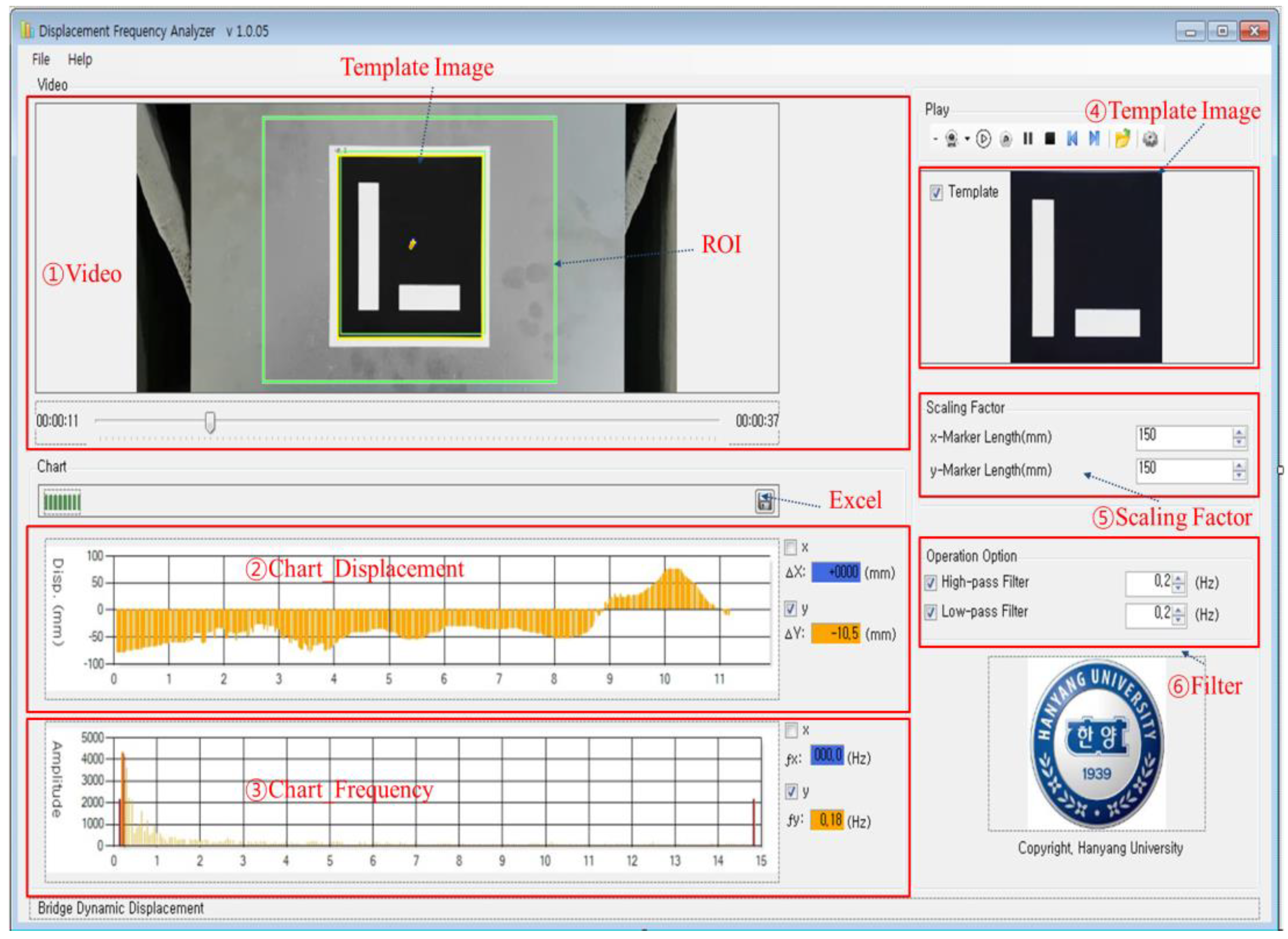
In this study, we developed software to accurately estimate bridge dynamic displacements based on the template-based matching technique and a homography-matrix. This software is operated on a Windows platform, and it is performed in a user-friendly graphical user interface (GUI). The programming tool for development the image processing software was used Visual Studio 2012 using C++ language. As shown in Figure 4, the developed software can import the motion images acquired from the smartphone camera, register the template image directly using the mouse on the video screen. Also, region of interest (ROI) can be set in the same way. The scaling factor is easily changed by inputting the length of the used marker. The software has been developed to fit the Galaxy S7 Samsung smartphone. However, it can be easily adapted to other smartphone models by changing the focal length through coding. In real time, the users can view the displacement curve through the chart screen. In addition, a fast Fourier transform (FFT) was applied to calculate the natural frequency of the bridge from displacement data. This software is a stand-alone executable program helpful for the measurement of bridge dynamic displacement. Through this software, the bridge dynamic displacements can be obtained easily by recognizing the movement of the pre-designed marker attached on the target using smartphone camera without expensive displacement sensors.
4. Experimental Validation
4.1. Laboratory Scale Tests
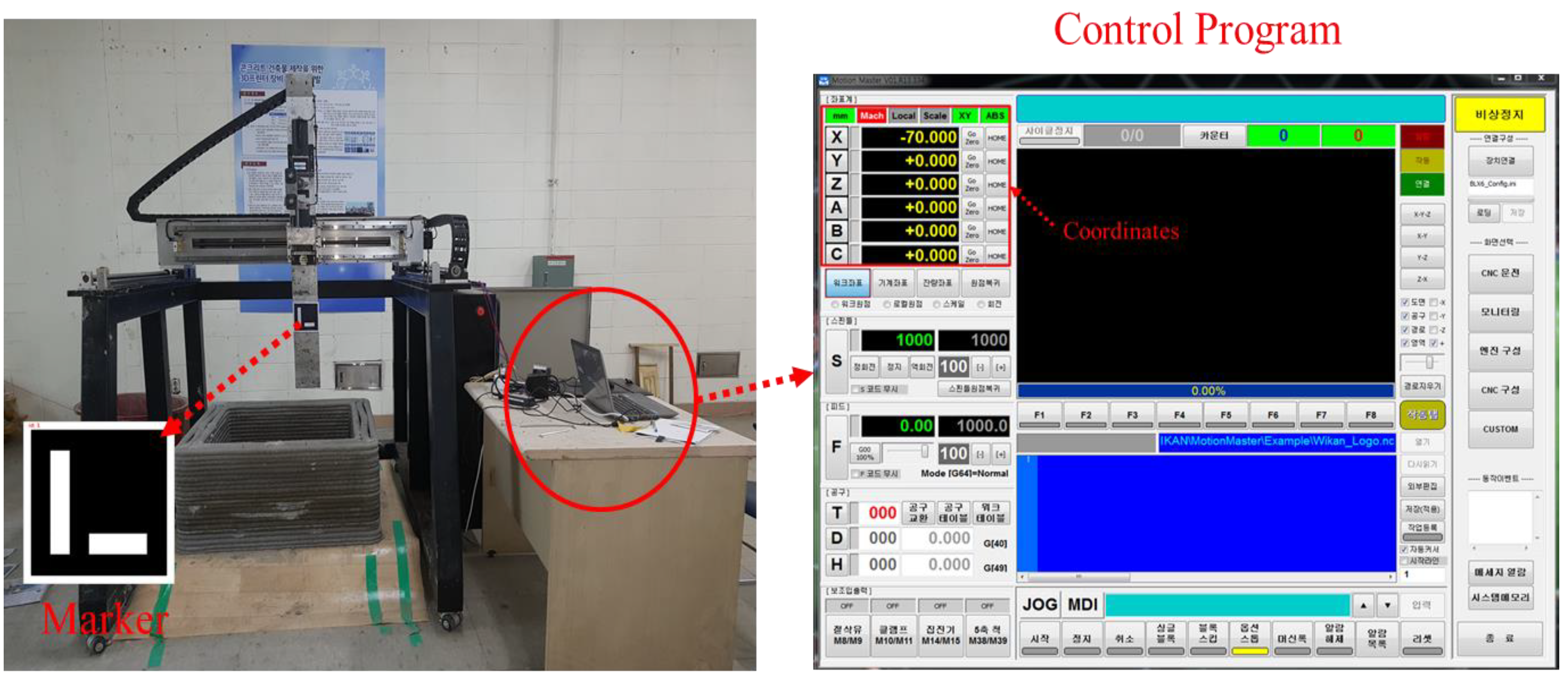
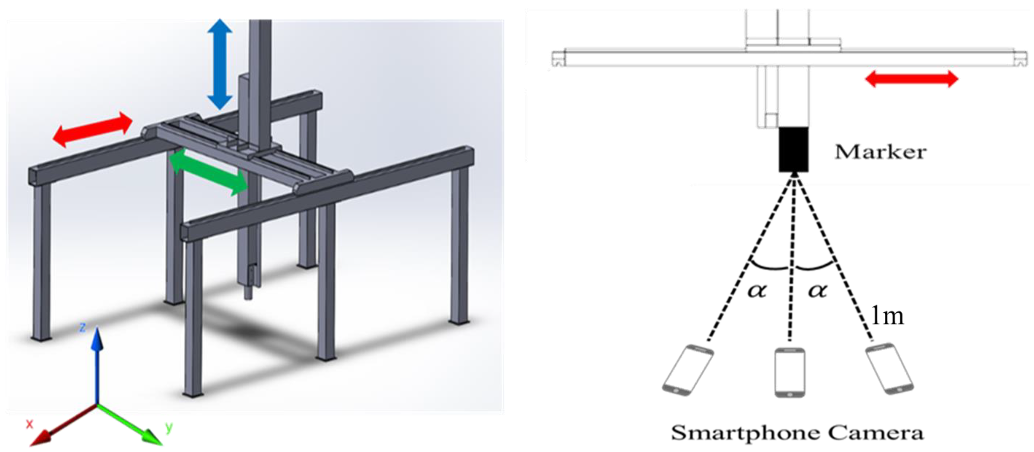
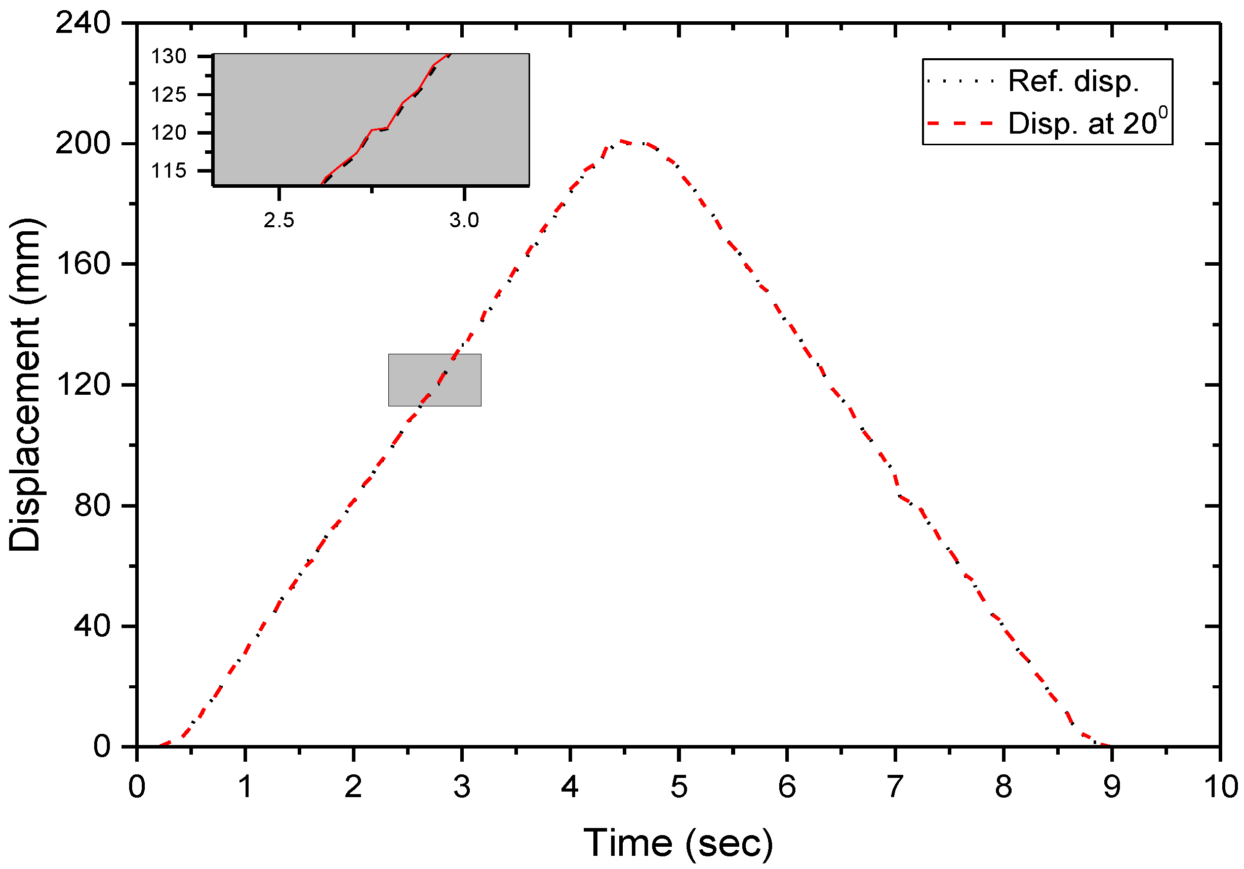
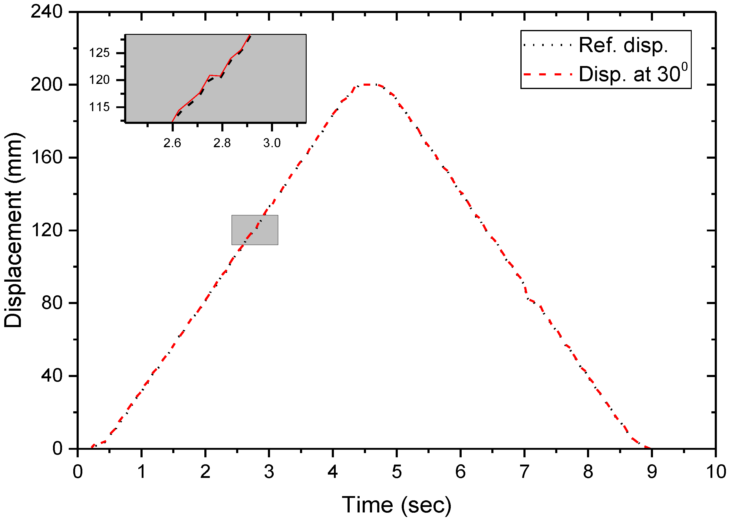
Initially, the performance of proposed computer vision-based bridge displacement measurement technique was evaluated at laboratory scale. In these experimental trials, specially design test equipment was used as shown in Figure 5. A predesigned black and white marker (150 mm × 150 mm) acting as tracking target, was fixed on computer numerical controlled (CNC) movement axis of machine. The linear repeated movement of the axis was fixed at 20 cm from origin point. To evaluate the proposed displacement measurement technique based on homographic matrix, motion images of marker attached movement axis were captured by successively placing the smartphone camera at angles of 0°, 10°, 20°, and 30° with reference to front of marker (shown in Figure 6). The marker’s motion images captured by the smartphone camera were recorded at 30 frames per second. The smartphone camera was placed at 1 m from the marker front side so that appropriate installation like field settings without any zoom can be tested. In these experiments, there was no need to install reference sensor to measure the displacement, as the marker is attached CNC movement axis. Thus, the CNC coordinates are more accurate compare to sensor readings and can easily be obtained from the control program. The marker’s motion images were recorded and transmitted to computer over wireless communication. The marker displacement readings obtained from the control program were regarded as reference-value and the errors of the proposed approached at various rotation angles were compared. We used Samsung Galaxy S7 smartphone for experimental trials. Table 1 summarizes the hardware specifications of computer vision-based system.
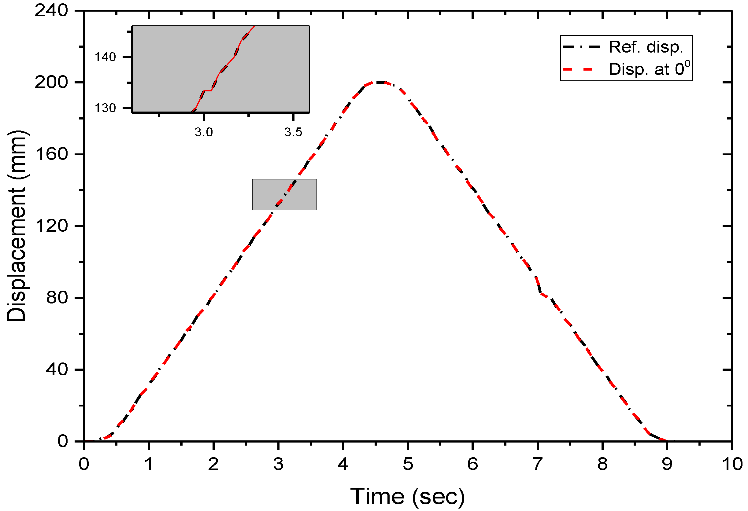
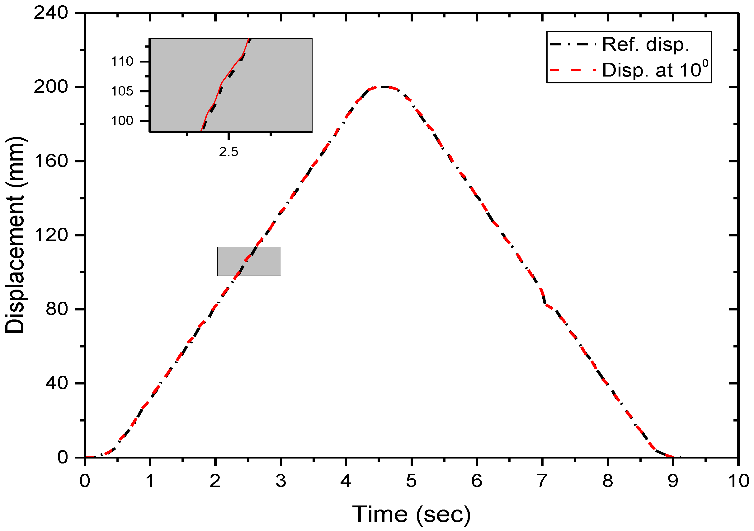
Figure 7, Figure 8, Figure 9 and Figure 10 show the measurement results of the displacement at different angles. We conducted error evaluation based on the root mean squared error (RMSE; Equation (4)) to quantify the measurement errors. Table 2 provides the calculated RMSE values for the bridge displacements.
- = ith set of bridge displacement data at time measured using the proposed method
- = ith set of bridge displacement data at time measured using LVDT
- n = number of data
The test results show that the proposed method provides a small change according to the angle between the smartphone camera and the marker. When the angle of the smartphone camera and the marker is 0°, RMSE value is 0.037 mm that is similar to the reference value. Although the error is increased by 0.371 mm when the angle is 10°, the magnitude of the error is sufficient to replace the existing displacement sensor. Also, RMSE value is 0.400 mm and 0.398 mm for the angle of 20° and 30°, respectively, that did not show any significant different compare to the angle of 10°. The proposed method maintains a minor error even when the angle increases that can measure accurate displacement of bridge in various range of the angle.
4.2. Field Test
The further experimental verification of proposed system has been performed field test. Like laboratory experiments, the computer vision system for the field test comprised a marker, a smartphone camera (Galaxy S7), and a computer installed with image processing software. In real field experiment, to reduce data transfer time, smartphone and computer were connected using data cable. The marker was an acrylic plate glued to metallic-plate to prevent deformation (Figure 11). The field tests were performed at Seongdong Bridge located in Seoul. In this field experiment, the displacement values obtained from the proposed vision-based approach were compared with conventional displacement sensors (LVDT). The acrylic plate marker was attached to the bridge girder using adhesives. The distance between smartphone camera and marker was set at 1 m and the angle was 0°. The motion images were recorded at 30 fps and transmitted to the computer. In field experimental setup of the proposed vision-based system is shown in Figure 11.
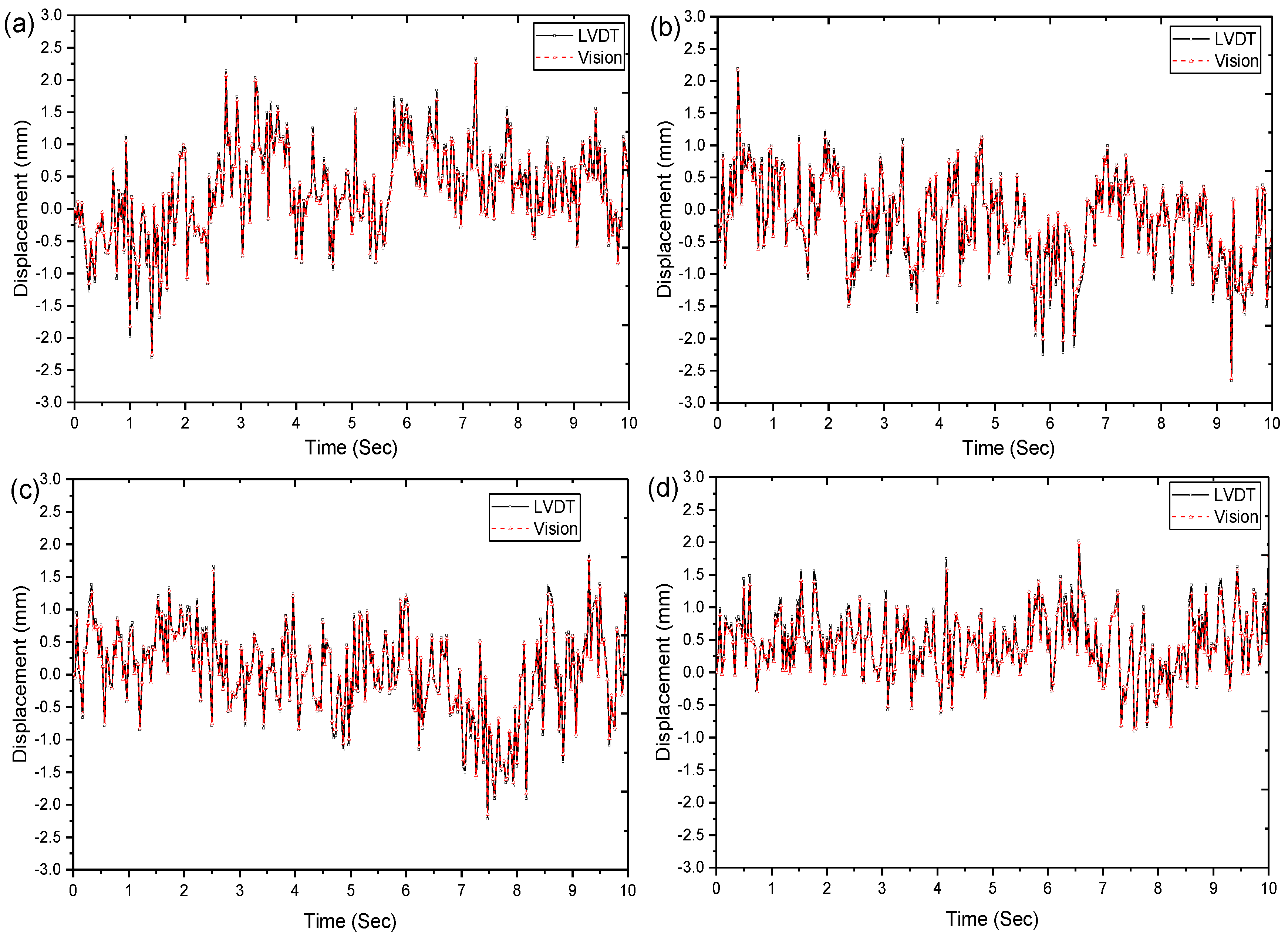
In the field test, two factors affecting measurement errors should are considered. The first factor to consider is the shaking of the smartphone camera caused by the wind, and the second factor is the influence of vibration around the smartphone camera due to vehicle traffic. Thus, a windless sunny day was selected for the field experimentation to minimize the errors and the trials were performed at the ambient vibration conditions. Using these experimental procedures, we obtained the dynamic displacements-time curve of the Seongdong Bridge by the proposed method and the LVDT. During the two-day test, we measured four sets of displacement data at the same point. The authors compared the displacement data measured by the proposed method and the measured values by the LVDT sensor. As shown in Figure 12, the measurements obtained using the proposed displacement measurement approach agree well with those from the conventional displacement sensor (LVDT).
Similar to the laboratory experiments, error analysis was performed using the RMSE of Equation (4) to quantify the accuracy of proposed method. Table 3 provides the calculated RMSE values that the values were slightly increased compared to the laboratory test. However, the proposed method demonstrated high measurement accuracy with a maximum RMSE value of 0.051 mm in the field. The proposed approach uses motion images obtained by portable devices, such as smartphone camera, to measure the bridge displacement. This technique requires no additional equipment and allows measurements at multiple locations in shorter time than when using conventional methods. Thus, the proposed method can effectively reduce monitoring time and cost compared to the method using conventional displacement sensor.
5. Limitations and Future Research
The accuracy of computer vision-based displacement measurement technique can even compete with conventional displacement sensors. It is also more efficient in terms of sensor installation cost and working time. The accuracy and efficiency of computer vision-based method has been verified by researchers. However, computer vision-based system requires a large-capacity server for data storage and database of images for the long-term monitoring as compared to existing sensors systems. Moreover, the camera performance and image processing algorithm significantly influence the quality of displacement data. In recent years, even though, several displacement measurement algorithms have been developed, yet it is difficult to find a highly suitable algorithm for structures monitoring. This limitation bounds the utilization for entire civil infrastructure. Another, drawback of computer vision approaches is the possibility of errors due to noise caused by the vibrations around the camera. The utilization of vibration control device such as gimbal may solve this problem.
6. Conclusions
The main objective of this study is to extend the measurable range and to enhance the accuracy of displacement measurement, so that computer vision-based systems can easily be adopted for the civil engineering structures (such as bridges). In this study, we introduced a computer vision-based technique for the measurement of rotation-invariant displacement with the successful utilization of a smartphone camera. The proposed method can transmit motion images acquired by using a smartphone camera to a remote computer using wireless communication. This computer vision-based approach combines two separate image-processing techniques: template-based matching and a homography matrix. As an initial step toward the implementation of this proposed method, we also calibrated the smartphone camera using hang’s calibration algorithm to eliminate lens distortion. The next step was marker tracking in the captured motion images. We applied template-based matching using NCC function as the image-processing algorithm to track the marker. To remove the geometric distortion, a planar projection method by homography-matrix was applied. Through this research, we developed GUI-based software for measuring bridge displacements with a user-friendly interface. In addition to laboratory scale testing, field tests were conducted to evaluate the performance of the proposed method. To quantify the measurement error, an error evaluation was performed based on the RMSE. The proposed method showed the accuracy of the displacement measurement even when the angle between the smartphone camera and the marker increased.
Significant advantages of the proposed system include low cost, ease of operation, and flexibility to extract bridge displacements at various angles from a single measurement, making this system highly applicable to civil structures.
Author Contributions
ByungWan Jo conceived the idea and provided the technical support and materials, Yun Sung Lee reviewed literature, carried out the experimentation, writing, and collected data and its management. Jun Ho Jo helped to set up experimental trials and Rana Muhammad Asad Khan helped in writing this paper.
Acknowledgments
We would like to thanks to the anonymous reviews, whose suggestion and reviews comments really helped us to improve the manuscript.
Conflicts of Interest
The authors have no conflicts of interest to declare.
References
- Chen, Z.; Zhou, X.; Wang, X.; Dong, L.; Qian, Y. Deployment of a smart structural health monitoring system for long-span arch bridges: A review and a case study. Sensors 2017, 17, 2151. [Google Scholar] [CrossRef] [PubMed]
- Vallan, A.; Casalicchio, M.L.; Perrone, G. Displacement and acceleration measurements in vibration tests using a fiber optic sensor. IEEE Trans. Instrum. Meas. 2010, 59, 1389–1396. [Google Scholar] [CrossRef]
- Sung, Y.-C.; Lin, T.-K.; Chiu, Y.-T.; Chang, K.-C.; Chen, K.-L.; Chang, C.-C. A bridge safety monitoring system for prestressed composite box-girder bridges with corrugated steel webs based on in-situ loading experiments and a long-term monitoring database. Eng. Struct. 2016, 126, 571–585. [Google Scholar] [CrossRef]
- Park, J.-W.; Sim, S.-H.; Jung, H.-J. Wireless displacement sensing system for bridges using multi-sensor fusion. Smart Mater. Struct. 2014, 23, 045022. [Google Scholar] [CrossRef]
- Lee, J.-J.; Shinozuka, M. Real-time displacement measurement of a flexible bridge using digital image processing techniques. Exp. Mech. 2006, 46, 105–114. [Google Scholar] [CrossRef]
- Fukuda, Y.; Feng, M.Q.; Shinozuka, M. Cost-effective vision-based system for monitoring dynamic response of civil engineering structures. Struct. Control Health Monit. 2010, 17, 918–936. [Google Scholar] [CrossRef]
- Ribeiro, D.; Calcada, R.; Ferreira, J.; Martins, T. Non-contact measurement of the dynamic displacement of railway bridges using an advanced video-based system. Eng. Struct. 2014, 75, 164–180. [Google Scholar] [CrossRef]
- Park, K.-T.; Kim, S.-H.; Park, H.-S.; Lee, K.-W. The determination of bridge displacement using measured acceleration. Eng. Struct. 2005, 27, 371–378. [Google Scholar] [CrossRef]
- Psimoulis, P.; Pytharouli, S.; Karambalis, D.; Stiros, S. Potential of global positioning system (GPS) to measure frequencies of oscillations of engineering structures. J. Sound Vib. 2008, 318, 606–623. [Google Scholar] [CrossRef]
- Abdel-Qader, L.; Abudayyeh, O.; Kelly, M.E. Analysis of edge-detection techniques for crack identification in bridges. J. Comput. Civ. Eng. 2003, 17, 255–263. [Google Scholar] [CrossRef]
- Koch, C.; Georgieva, K.; Kasireddy, V.; Akinci, B.; Fieguth, P. A review on computer vision based defect detection and condition assessment of concrete and asphalt civil infrastructure. Adv. Eng. Inform. 2015, 29, 196–210. [Google Scholar] [CrossRef]
- Ye, X.; Dong, C.; Liu, T. A review of machine vision-based structural health monitoring: Methodologies and applications. J. Sens. 2016, 2016. [Google Scholar] [CrossRef]
- Stephen, G.; Brownjohn, J.; Taylor, C. Measurements of static and dynamic displacement from visual monitoring of the humber bridge. Eng. Struct. 1993, 15, 197–208. [Google Scholar] [CrossRef] [Green Version]
- Olaszek, P. Investigation of the dynamic characteristic of bridge structures using a computer vision method. Measurement 1999, 25, 227–236. [Google Scholar] [CrossRef]
- Guo, J. Dynamic displacement measurement of large-scale structures based on the lucas–kanade template tracking algorithm. Mech. Syst. Signal Process. 2016, 66, 425–436. [Google Scholar] [CrossRef]
- Shan, B.; Wang, L.; Huo, X.; Yuan, W.; Xue, Z. A bridge deflection monitoring system based on CCD. Adv. Mater. Sci. Eng. 2016, 2016. [Google Scholar] [CrossRef]
- Zhang, Z. A flexible new technique for camera calibration. IEEE Trans. Pattern Anal. Mach. Intell. 2000, 22, 1330–1334. [Google Scholar] [CrossRef]
- Feng, D.; Feng, M.Q. Identification of structural stiffness and excitation forces in time domain using noncontact vision-based displacement measurement. J. Sound Vib. 2017, 406, 15–28. [Google Scholar] [CrossRef]
- Feng, D.; Feng, M.Q. Experimental validation of cost-effective vision-based structural health monitoring. Mech. Syst. Signal Process. 2017, 88, 199–211. [Google Scholar] [CrossRef]
- Yoon, H.; Elanwar, H.; Choi, H.; Golparvar-Fard, M.; Spencer, B.F. Target-free approach for vision-based structural system identification using consumer-grade cameras. Struct. Control Health Monit. 2016, 23, 1405–1416. [Google Scholar] [CrossRef]
- Brunelli, R. Template Matching Techniques in Computer Vision: Theory and Practice; John Wiley & Sons: New York, NY, USA, 2009. [Google Scholar]
- Peters, W.; Ranson, W. Digital imaging techniques in experimental stress analysis. Opt. Eng. 1982, 21, 213427. [Google Scholar] [CrossRef]
- Peters, W.; Ranson, W.; Sutton, M.; Chu, T.; Anderson, J. Application of digital correlation methods to rigid body mechanics. Opt. Eng. 1983, 22, 226738. [Google Scholar] [CrossRef]
- Sutton, M.; Mingqi, C.; Peters, W.; Chao, Y.; McNeill, S. Application of an optimized digital correlation method to planar deformation analysis. Image Vis. Comput. 1986, 4, 143–150. [Google Scholar] [CrossRef]
- Pan, B.; Li, K.; Tong, W. Fast, robust and accurate digital image correlation calculation without redundant computations. Exp. Mech. 2013, 53, 1277–1289. [Google Scholar] [CrossRef]
- Chen, J.; Jin, G.; Meng, L. Applications of digital correlation method to structure inspection. Tsinghua Sci. Technol. 2007, 12, 237–243. [Google Scholar] [CrossRef]
- Yoneyama, S.; Kitagawa, A.; Iwata, S.; Tani, K.; Kikuta, H. Bridge deflection measurement using digital image correlation. Exp. Tech. 2007, 31, 34–40. [Google Scholar] [CrossRef]
- Lewis, J. Fast normalized cross-correlation, In Vision Interface; Canadian Image Processing and Pattern Recognition Society: Quebec City, QC, Canada, 1995; Volume 10, pp. 120–123. [Google Scholar]
- Jeong, Y.; Park, D.; Park, K.H. Ptz camera-based displacement sensor system with perspective distortion correction unit for early detection of building destruction. Sensors 2017, 17, 430. [Google Scholar] [CrossRef] [PubMed]
- Hartley, R.; Zisserman, A. Multiple View Geometry in Computer Vision; Cambridge University Press: Cabridge, UK, 2003. [Google Scholar]
- Luo, J.; Konofagou, E.E. A fast normalized cross-correlation calculation method for motion estimation. IEEE Trans. Ultrason. Ferroelectr. Freq. Control 2010, 57, 1347–1357. [Google Scholar] [PubMed]
- Abdulfattah, G.; Ahmad, M. Face localization-based template matching approach using new similarity measurements. J. Theor. Appl. Inf. Technol. 2013, 57, 424–431. [Google Scholar]
- Dawoud, N.N.; Samir, B.B.; Janier, J. Fast template matching method based optimized sum of absolute difference algorithm for face localization. Int. J. Comput. Appl. 2011, 18, 30–34. [Google Scholar]
- Kim, S.-W.; Lee, S.-S.; Kim, N.-S.; Kim, D.-J. Numerical model validation for a prestressed concrete girder bridge by using image signals. KSCE J. Civ. Eng. 2013, 17, 509. [Google Scholar] [CrossRef]
- Kim, S.-W.; Jeon, B.-G.; Kim, N.-S.; Park, J.-C. Vision-based monitoring system for evaluating cable tensile forces on a cable-stayed bridge. Struct. Health Monit. 2013, 12, 440–456. [Google Scholar] [CrossRef]
- Jáuregui, D.V.; White, K.R.; Woodward, C.B.; Leitch, K.R. Noncontact photogrammetric measurement of vertical bridge deflection. J. Bridge Eng. 2003, 8, 212–222. [Google Scholar] [CrossRef]
- Poudel, U.; Fu, G.; Ye, J. Structural damage detection using digital video imaging technique and wavelet transformation. J. Sound Vib. 2005, 286, 869–895. [Google Scholar] [CrossRef]
- Fu, G.; Moosa, A.G. An optical approach to structural displacement measurement and its application. J. Eng. Mech. 2002, 128, 511–520. [Google Scholar] [CrossRef]
- Wahbeh, A.M.; Caffrey, J.P.; Masri, S.F. A vision-based approach for the direct measurement of displacements in vibrating systems. Smart Mater. Struct. 2003, 12, 785. [Google Scholar] [CrossRef]
- Kohut, P.; Holak, K.; Uhl, T.; Ortyl, Ł.; Owerko, T.; Kuras, P.; Kocierz, R. Monitoring of a civil structure’s state based on noncontact measurements. Struct. Health Monit. 2013, 12, 411–429. [Google Scholar] [CrossRef]
- Lee, J.J.; Shinozuka, M. A vision-based system for remote sensing of bridge displacement. NDT E Int. 2006, 39, 425–431. [Google Scholar] [CrossRef]
- Lee, J.J.; Shinozuka, M.; Lee, C.G. Evaluation of bridge load carrying capacity based on dynamic displacement measurement using real-time image processing techniques. Int. J. Steel Struct. 2006, 6, 377–385. [Google Scholar]
- Choi, H.-S.; Cheung, J.-H.; Kim, S.-H.; Ahn, J.-H. Structural dynamic displacement vision system using digital image processing. NDT E Int. 2011, 44, 597–608. [Google Scholar] [CrossRef]
- Ho, H.-N.; Lee, J.-H.; Park, Y.-S.; Lee, J.-J. A synchronized multipoint vision-based system for displacement measurement of civil infrastructures. Sci. World J. 2012, 2012. [Google Scholar] [CrossRef] [PubMed]
- Tian, L.; Pan, B. Remote bridge deflection measurement using an advanced video deflectometer and actively illuminated led targets. Sensors 2016, 16, 1344. [Google Scholar] [CrossRef] [PubMed]
- Busca, G.; Cigada, A.; Mazzoleni, P.; Zappa, E. Vibration monitoring of multiple bridge points by means of a unique vision-based measuring system. Exp. Mech. 2014, 54, 255–271. [Google Scholar] [CrossRef]
- Feng, D.M.; Feng, M.Q.; Ozer, E.; Fukuda, Y. A vision-based sensor for noncontact structural displacement measurement. Sensors 2015, 15, 16557–16575. [Google Scholar] [CrossRef] [PubMed]
- Feng, M.Q.; Fukuda, Y.; Feng, D.; Mizuta, M. Nontarget vision sensor for remote measurement of bridge dynamic response. J. Bridge Eng. 2015, 20, 04015023. [Google Scholar] [CrossRef]
- Jeon, H.; Bang, Y.; Myung, H. A paired visual servoing system for 6-dof displacement measurement of structures. Smart Mater. Struct. 2011, 20, 045019. [Google Scholar] [CrossRef]
- Park, S.; Park, H.; Kim, J.; Adeli, H. 3D displacement measurement model for health monitoring of structures using a motion capture system. Measurement 2015, 59, 352–362. [Google Scholar] [CrossRef]
- Chang, C.; Xiao, X. Three-dimensional structural translation and rotation measurement using monocular videogrammetry. J. Eng. Mech. 2009, 136, 840–848. [Google Scholar] [CrossRef]
- Ji, Y.; Chang, C. Nontarget image-based technique for small cable vibration measurement. J. Bridge Eng. 2008, 13, 34–42. [Google Scholar] [CrossRef]
- Ji, Y.; Chang, C. Nontarget stereo vision technique for spatiotemporal response measurement of line-like structures. J. Eng. Mech. 2008, 134, 466–474. [Google Scholar] [CrossRef]
- Kim, S.-W.; Kim, N.-S. Dynamic characteristics of suspension bridge hanger cables using digital image processing. NDT E Int. 2013, 59, 25–33. [Google Scholar] [CrossRef]
- Kim, B.H. Extracting modal parameters of a cable on shaky motion pictures. Mech. Syst. Signal Process. 2014, 49, 3–12. [Google Scholar] [CrossRef]
- Chen, C.-C.; Wu, W.-H.; Tseng, H.-Z.; Chen, C.-H.; Lai, G. Application of digital photogrammetry techniques in identifying the mode shape ratios of stay cables with multiple camcorders. Measurement 2015, 75, 134–146. [Google Scholar] [CrossRef]
- Zhao, X.; Ri, K.; Han, R.; Yu, Y.; Li, M.; Ou, J. Experimental research on quick structural health monitoring technique for bridges using smartphone. Adv. Mater. Sci. Eng. 2016, 2016. [Google Scholar] [CrossRef]
- Zhao, X.; Ri, K.; Wang, N. Experimental verification for cable force estimation using handheld shooting of smartphones. J. Sens. 2017, 2017. [Google Scholar] [CrossRef]
Figure 1.
Schematics and Flowchart of the Proposed Methodology.

Figure 2.
Basic Concept of the Template-based Matching Technique.

Figure 3.
Basic Concept of Planar Projection using a Homography-Matrix.

Figure 4.
Interface of software for the measurement of bridge displacements.

Figure 5.
Setup of the Laboratory Tests.

Figure 6.
Movement Mechanism of Test Equipment and Angle of Smartphone Camera.

Figure 7.
Angle of Smartphone Camera = 0°.

Figure 8.
Angle of Smartphone Camera = 10°.

Figure 9.
Angle of Smartphone Camera = 20°.

Figure 10.
Angle of Smartphone Camera = 30°.

Figure 11.
Schematic of the experimental setup of the proposed system.

Figure 12.
Comparison evaluation of Measured Displacement: (a) Data 1; (b) Data 2; (c) Data 3; (d) Data 4.
Figure 12.
Comparison evaluation of Measured Displacement: (a) Data 1; (b) Data 2; (c) Data 3; (d) Data 4.


Table 1.
The hardware configuration of Computer Vision System.
| Types | Models | Specifications |
|---|---|---|
| Marker | - | - Two white rectangles with dark background - Length: 150 mm × 150 mm |
| Smartphone Camera | SM-G930S | Image sensor: Sony IMX260 UHD 4K (3840 × 2160) resolution @30 fps Aperture: f/1.7 Pixel size: 1.4 µm Focal length: 4.20 mm |
| Computer | Samsung- NT870Z5G | Intel(R) Core(TM) i7-4720HQ CPU 2.60 GHZ 8.00 GB RAM Windows 10 (64-bit) |
Table 2.
Measurement errors (root mean squared error (RMSE)).
| 0° | 10° | 20° | 30° | |
|---|---|---|---|---|
| RMSE | 0.037 | 0.371 | 0.400 | 0.398 |
Table 3.
Measurement errors (RMSE).
| (a) | (b) | (c) | (d) | Max. | Min. | |
|---|---|---|---|---|---|---|
| RMSE | 0.044 | 0.051 | 0.040 | 0.050 | 0.051 | 0.040 |
© 2018 by the authors. Licensee MDPI, Basel, Switzerland. This article is an open access article distributed under the terms and conditions of the Creative Commons Attribution (CC BY) license (http://creativecommons.org/licenses/by/4.0/).
Share and Cite
MDPI and ACS Style
Jo, B.-W.; Lee, Y.-S.; Jo, J.H.; Khan, R.M.A. Computer Vision-Based Bridge Displacement Measurements Using Rotation-Invariant Image Processing Technique. Sustainability 2018, 10, 1785. https://doi.org/10.3390/su10061785
AMA Style
Jo B-W, Lee Y-S, Jo JH, Khan RMA. Computer Vision-Based Bridge Displacement Measurements Using Rotation-Invariant Image Processing Technique. Sustainability. 2018; 10(6):1785. https://doi.org/10.3390/su10061785
Chicago/Turabian StyleJo, Byung-Wan, Yun-Sung Lee, Jun Ho Jo, and Rana Muhammad Asad Khan. 2018. "Computer Vision-Based Bridge Displacement Measurements Using Rotation-Invariant Image Processing Technique" Sustainability 10, no. 6: 1785. https://doi.org/10.3390/su10061785
Note that from the first issue of 2016, this journal uses article numbers instead of page numbers. See further details here.