A Communication-Supported Comprehensive Protection Strategy for Converter-Interfaced Islanded Microgrids


1
Goldwind Science and Etechwin Electric Co., Ltd., BDA, Beijing 100176, China
2
North China Electric Power University, Changping District, Beijing 102206, China
*
Author to whom correspondence should be addressed.
Sustainability 2018, 10(5), 1335; https://doi.org/10.3390/su10051335
Submission received: 3 April 2018
/
Revised: 15 April 2018
/
Accepted: 19 April 2018
/
Published: 25 April 2018
(This article belongs to the Special Issue Smart Power Grid for Sustainable Energy Transition)
Abstract
:The deployment of distributed generators (DGs) gives rise to several challenges for a microgrid or conventional distribution feeder, regarding control and protection issues. The major ones are: bi-directional flow of power, changes in fault current magnitude, and continuous changes in operational configuration due to both the plug-and-play of DGs and loads, and the intermittency of the renewable DGs. This issue is exacerbated when the microgrid contains several converter-interfaced DGs and operates in the islanded mode of operation. Hence, conventional protection strategies and relaying techniques will no longer be sufficient to protect islanded microgrids against network faults and disturbance conditions. This paper proposes a fast and reliable communication-supported protection strategy for ensuring the safe operation of converter-interfaced islanded microgrids. The strategy is implementable using commercially accessible microprocessor based digital relays, and is applicable for the protection of low voltage islanded microgrids. It provides backup protection to handle communication failures and malfunctions of protective devices. The paper also presents the detailed structural layout of the digital relay, which executes the proposed protection strategy. A number of improvements are proposed to find an alternative method for conventional overcurrent relays to reliably detect small-magnitude fault currents and high impedance faults, commonly encountered in converter-interfaced islanded microgrids. A simple and economical bus protection method is also proposed. Several simulations are conducted on a comprehensive model of a realistic operational industrial microgrid (Goldwind Smart Microgrid System) using PSCAD/EMTDC software environment—for different case studies and fault scenarios—to verify the effectiveness of the present strategy and its digital relay.
1. Introduction
Hybrid energy systems containing distributed generators (DGs), powered by micro-sources such as photovoltaic power systems, microturbines, wind power systems, mini-hydros, and fuel cells have been gaining acceptance among power industries and utilities because of their easy accessibility (the renewables: especially wind and solar), reduced-emissions (environmental friendly clean energy), simplicity (less complex structure), enhanced operational efficiency, and higher reliability. The growing penetration of DGs and the existence of hybrid decentralized energy systems, with several DGs in electrical proximity to each other, have resulted in the idea of the microgrid [1]. A microgrid is a set of interconnected loads, DGs, and energy storage systems at a distribution level with distinct electrical boundaries. It has a black start capability and can operate either in islanded mode—independent from the main grid—or grid-connected mode—in parallel with other microgrids or the main utility grid. It provides continuous supply to end-users, improves power quality, operational optimality, and reliability [1,2,3,4]. Due to the special features of microgrids, traditional power system protection and control strategies which rely on large fault current and unidirectional power flow assumptions of radial network structure are not sufficient for operating microgrids [5,6].
The major issue regarding microgrid protection are in the islanded mode of operation, where the microgrid is operated independently from the main utility grid as a self-contained system. In this operation mode, fault currents are comparatively small (about twice the rated normal current), because of the restricted current ratings of the semiconductor switches used in the converters of power electronic interfaced DGs. Thus, traditional overcurrent protection is not sufficient for the protection of microgrids operating in islanded mode of operation and isolated microgrids, which are not physically connected to the main utility grid [7,8,9,10,11,12,13]. However, the main utility grid contributes to fault currents in the grid-connected mode of operation and, as such, the fault currents required to actuate conventional overcurrent relays are relatively large. Though it is possible to employ conventional overcurrent relays for the protection of microgrids operating in a grid-connected mode of operation and non-isolated microgrids, which are always physically connected with the main utility grid, the present-day relay settings should be systematically adjusted, as the existence of DGs may compromise the coordination of the protection system [6,14,15,16,17].
Admittance relay based protection for microgrids operating in both modes of operation has been proposed in Dewadasa et al. [7]. However, it does not reveal a reliable technique for measuring the exact line admittance value for various fault types and locations, especially for short distribution lines. In addition, coordination among the proposed relays has not been fully examined in the paper.
Analyses of the system voltage for the fault protection of microgrids have been presented by some researchers [9,10,18]. The technique proposed in Al-Nasseri et al. [10], for instance, utilizes Park-transformed (dq0 frame) system voltage for fault detection and isolation within a microgrid. However, it neither quantifies the Park-transformed fault detection voltage signal for different solid fault scenarios, nor does it ensure protection against high impedance faults (HIFs). Moreover, the strategy in this paper does not describe the structure of the relay enabling the desired protection. In Sortomme et al. [11], a communication-aided scheme realized using digital relays is presented for the protection of a microgrid. Despite its being a successful scheme, it is very expensive and requires technical aspects that are not available in existing electrical technology. Besides, the scheme is based on differential currents, while disregarding the error and differences among current transformers.
Jayawarna et al. [12] presents the deployment of electrical energy storages (ESSs) having large short circuit contribution potential within a microgrid. The presented strategy allows conventional overcurrent protections for microgrids to be used, even in the islanded operation mode. However, it is costly and requires adaptive protective devices. These protection schemes are based on large fault current magnitudes to detect faults, and are unable to guarantee reliable operation of an islanded microgrid since they do not provide a protection scheme for islanded operation mode.
Zamani et al. [13] has presented a protection scheme and a microprocessor implementable relay for protecting low voltage microgrids. The proposed scheme offers protection for both microgrid operation modes, and does not depend upon communication infrastructures. However, it may take a comparatively long time to detect and isolate a fault within a large medium voltage microgrid, specifically in the islanded operation mode, due to the definite-time grading approach it applies.
Zamani et al. [19] has proposed a faster communication-aided protection scheme and a microprocessor implementable relay for protecting large sized medium voltage microgrids. The scheme can provide quick and accurate fault clearance in a coordinated way for both modes of the microgrid’s operation. However, the scheme employs under-voltage protection algorithms for the detection and isolation of solid faults in the islanded mode of operation. This may lead the relays to send unwanted tripping commands to circuit breakers, due to short-duration incidence of voltage sags [20], which always exist due to temporary fluctuation of loads and the intermittency of renewable sources in the microgrid, unless proper settings have been set regarding these issues. Moreover, the protection scheme in the paper neither ensures protection against symmetrical HIFs, nor provides methods for busbar protection.
Lai et al. [21] and Kexing et al. [22] have proposed a comprehensive protection strategy for microgrids operating in the islanded mode by employing microprocessor based intelligent relays. These strategies provide solutions to microgrid protection problems resulting from HIFs and unnecessary outage of important DGs and loads. They employ adaptive overcurrent (50/51) relays to detect solid fault occurrences in the microgrid. However, although adaptive, overcurrent relays may fail to detect faults in islanded microgrids, as the potential fault current is usually small. Moreover, the protection strategies in these papers do not ensure protection against all types of HIFs.
Table 1 summarizes the comparison of the different protection schemes reported in this paper.
This paper proposes a rapid and reliable protection strategy for low voltage microgrids operating in the islanded mode of operation or physically isolated from the main utility grid. It employs a programmable microprocessor based digital relays. The paper presents the architectural structure of this digital relay which executes the proposed protection scheme. Such relays target the detection and isolation of faults within islanded microgrids in a coordinated way. They are able to communicate with each other and with the microgrid central protection manager (MCPM). The MCPM also communicates with the microgrid stability control and load management systems. Online tuning of the relay settings in a decentralized approach is also possible, whenever necessary. The proposed scheme offers main and backup protections against all types of solid faults and HIFs at different potential fault locations within the case study microgrid. Several simulations are conducted on a comprehensive model of a realistic operational industrial microgrid (Goldwind Smart Microgrid System) using PSCAD/EMTDC software environment, for different case studies and fault scenarios, to verify the effectiveness of the presented strategy and its digital relay.
2. Proposed Relay Structure
In this paper, a communication-supported protection strategy is presented for low voltage microgrids. The presented protection strategy employs digital relays to detect faults and to isolate the smallest part of the microgrid network affected by the faults in a selective manner. The presented protection strategy is executed by a proposed relay, henceforth called the “microgrid protection digital relay” (MPDR). The aim of this section is to highlight the structural configuration, functional modules, and important features of the MPDR. If an MPDR has the ability to communicate with other MPDRs, the microgrid operator and other devices in the microgrid, it is called a “communication-supported microgrid protection digital relay” (CMPDR).
As discussed in Section 1, the deployment of DGs causes a microgrid or conventional distribution feeder to face several challenges, regarding control and protection issues. The major ones are: (1) bi-directional flow of power; (2) changes in fault current magnitude; and (3) continuous changes in operational configuration due to plug-and-play of DGs and loads, and intermittency of the renewable sources. As a result, conventional protection strategies and relaying techniques will no longer be sufficient and, hence, the relay settings should be readjusted for the grid-connected operation mode [17]. Specifically, directional elements are necessary to avoid false tripping when a fault affects an adjacent protection zone. The directional element of the adjacent zone quickly blocks its circuit breaker(s), for a given period of time, to allow the protection (primary) devices of the faulty zone to operate and isolate the fault. If the fault persists however, the circuit breaker(s) of the adjacent protection zone is configured to open, as backup protection after the primary protection relay(s) reverse definite time elapses.
Conversely, fault currents are comparatively small in physically isolated microgrids, or the islanded operation mode as introduced in Section 1. This is because converter interfaced DGs cannot introduce large fault currents into the microgrid system, as their rated output currents are restricted by the ratings of the constituent semiconductor devices of the converters. In fact, the absence of the main grid, which could contribute large fault currents, is the other reason for the reduced fault current magnitudes in the islanded mode of operation. Hence, traditional overcurrent relays are ineffective for the protection of islanded microgrids. On the other hand, a bolted/solid fault within an islanded microgrid leads to a significant voltage drop that could be used as fault detection signal. For an HIF, however, this voltage drop may not be big enough to actuate the protection relays. As a result, the undervoltage protection may not be able to identify a faulty condition from disturbance-caused voltage sag or overload conditions, thus calling for effective and alternative techniques, which are discussed in Section 2.1 and Section 2.2.
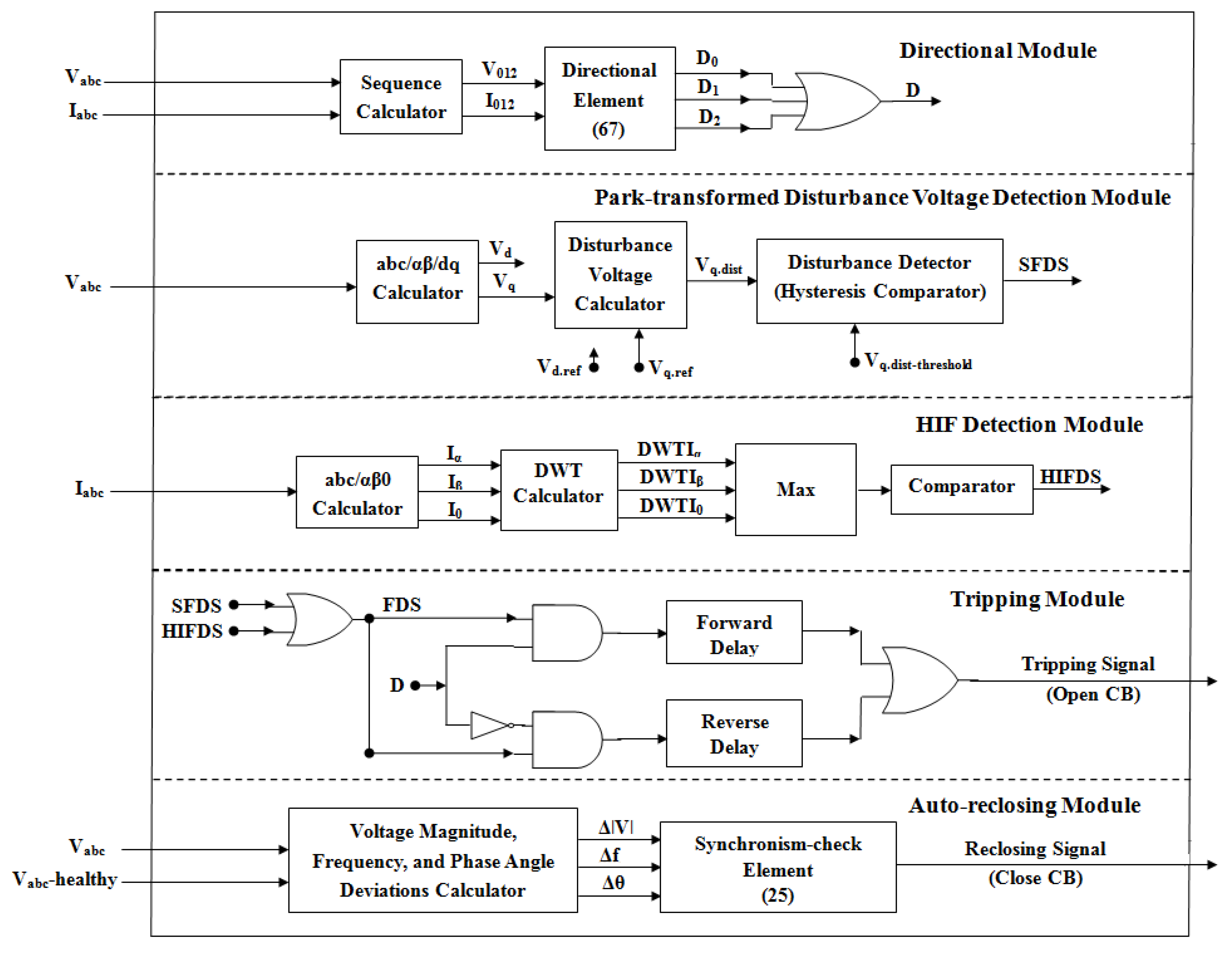
The previously mentioned protection functions can be integrated into commercially available digital relays. Figure 1 shows the schematic diagram and functional units of the proposed MPDR/CMPDR, which is the modified version of the relays presented in Zamani et al. [19] and Lai et al. [21]. As shown in Figure 1, five modules exist in an MPDR/CMPDR: “the directional module”, “the park-transformed disturbance voltage based detection module”, “the HIF detection module,” “the tripping module,” and “the auto-reclosing module”.
The directional element determines the direction of the fault current (power flow) based on the directional decision making principles presented in Section 2.3. The park-transformed disturbance voltage detection based protection module consists of abc/αβ/dq calculator, disturbance voltage calculator, and disturbance detector (hysteresis comparator). The abc/αβ/dq calculator transforms the three-phase ac voltage to the two-phase stationary reference frame (αβ), and then to the rotating reference frame (dq). The disturbance voltage calculator computes the disturbance (error) voltage magnitude by comparing the measured dq voltage values with a given reference dq voltage values. The disturbance detector, a dual hysteresis comparator, finally determines whether a solid fault has occurred by comparing the detected disturbance voltage signal against its upper and lower threshold values. The detailed mathematical analysis and functional principles of this module are presented in Section 2.1. The HIF detection module determines the occurrence of HIFs based on travelling wave fronts (wavelet coefficients) extracted from current transients observed at the faulty section. The multi-resolution analysis (MRA) output based discrete wavelet transform (DWT) is used to obtain the wave fronts. Finally, the outputs of the directional module, park-transformed disturbance voltage detection based protection module, and HIF detection module are used by the tripping module to determine whether or not a trip signal shall be issued. The auto-reclosing module is employed to guarantee safe reconnection of the isolated part of the network to the rest (i.e., the healthy part) of the microgrid network after the fault has effectively cleared.
2.1. Park-Transformed Disturbance Voltage Based Solid Fault Detection
2.1.1. Basic Principle of Disturbance Voltage Detection
Three-phase instantaneous voltages at the respective MPDR/CMPDR (at the DG terminal, bus, branch, feeder line, distribution line, or any other protected component) are measured by using a potential transformer (PT). This is transformed to the two-phase stationary reference frame (αβ) [23], and then to the synchronous rotating reference frame (dq) [24], using Equations (1) and (2) respectively.
The three-phase voltages, Va, Vb and Vc, are transformed to the two-phase quadrature voltages, Vα and Vβ, and then to the DC voltages, Vd and Vq. Any variation of the three-phase ac voltage can be reflected by the variation of the voltage in d-q coordinate system. In this paper, the q-axis voltage component in d-q coordinate system is chosen as the fault detection signal, and given by (3).
Any disturbance on the microgrid system voltage due to fault occurrence will be reflected as disturbance in the d-q values. Using the disturbed d-q values it is possible to obtain the disturbance signal, Vq.dist, which represents the deviation of the microgrid system voltages from a given reference. Vq.dist is able to detect the time when a fault occurs and clears. It also provides an appropriate signal to distinguish the different fault types.
To obtain the disturbance voltage (Vq.dist) a reference q-axis voltage, Vq.ref, corresponding to a set of three-phase balanced reference voltages is used. This represents a constant DC value in d-q synchronous rotating frame. The q-axis component of the d-q voltage obtained from (3) is compared against the given reference value, and is expressed as:
Under normal conditions, the Vq value obtained from (3) should be equal to the given reference value. When this condition is met the value of Vq.dist is zero; otherwise Vq.dist is a DC signal varying according to the nature of the fault.
2.1.2. Symmetrical Fault Detection
When a symmetrical fault occurs in the microgrid, the three-phase voltages are still balanced, and can be expressed as:
where, Vm is the peak phase voltage; n is the harmonic order, it denotes the fundamental voltage when n equals 1; ω = 2πf is the angular frequency of the system voltage; ϕ is the initial phase angle of the system voltage.
Substituting Equation (5) in (3) gives:
For balanced or synchronous operation, the rotor speed ωr is equal to the angular frequency of the stator voltages. Hence,
Thus, the disturbance voltage for symmetrical fault, Vq.dist is given by:
Hence, for a symmetrical (three-phase) fault, Vq.dist is pure DC voltage. In other words, any AC disturbance on the three-phase voltage due to symmetrical fault in the abc reference frame appears as constant or DC disturbance in the dq reference frame.
2.1.3. Unsymmetrical Fault Detection
Any unsymmetrical fault occurring in microgrids will result in unbalanced three-phase voltage. Then Vd and Vq will have positive, negative and zero sequence components. In order to reduce the complexity of the Clarke and Park transformations due to the addition of the negative- and zero-sequence voltage components, the zero-sequence voltage is first subtracted from the three-phase voltage.
The zero-sequence voltage component can be expressed as:
where, Va, Vb and Vc are the three-phase voltage for a, b, and c phases respectively, then the three-phase voltages, excluding the zero sequence components, can be expressed as:
V’a, V’b and V’c can be decomposed into positive- and negative-sequence components, then the three-phase fundamental voltages are given by:
where, VPm and VNm denote the peak values of the positive- and negative-sequence fundamental voltages, respectively; ω = 2πf is the angular frequency of the microgrid system voltage; ϕP and ϕN are the initial phase angle values of the positive- and negative-sequence fundamental voltages, respectively.
The three-phase voltages V’a, V’b and V’c can be transformed to the voltage in the synchronous rotating reference frame, dq frame, using (1) and (2). Substituting (12) in (3) for the three-phase voltages gives:
Substituting (7) in (13) for θ gives:
Thus, the disturbance voltage for unsymmetrical faults is given by:
Hence, for unsymmetrical faults in microgrids, Vq.dist not only have a DC component, but also have a ripple component with twice of the fundamental frequency, 2ω.
This means, alternating variation on the three-phase voltage in the ABC reference frame due to an unsymmetrical fault appears as ripple or oscillating signal, plus a DC component in the dq reference frame. It will be a DC voltage with an AC ripple for a two-phase fault and an oscillating signal varying between zero and a maximum value for a single-phase fault. These characteristics of the signals are used to identify the different types of faults.
Thus, according to the proposed protection strategy, the Park-transformed disturbance voltage detection based protection module of the CMPDR finally determines whether a solid fault has been detected within its jurisdiction by comparing the detected disturbance voltage signal against the upper and lower threshold values of a dual hysteresis comparator. If the detected disturbance voltage increases by more than the specified threshold, the module will send a solid fault detection signal (SFDS) to the tripping module of the CMPDR.
2.2. High Impedance Fault (HIF) Detection
HIFs are not easy to detect using conventional relaying techniques. Though several techniques have been proposed in previous studies to deal with the issue [25,26,27], no complete solution exists so far. This paper presents a method for HIF detection that fundamentally depends on the measurement of travelling wave fronts (wavelet coefficients) extracted from current transients observed at the fault impacted branches [28].
In this method, the three phase branch currents measured on each of the protected devices are first transformed into the modal domain (αβ0 frame) using the abc/αβ0 calculator; then, the wave fronts (discrete wavelet coefficients (DWTCs)) of these modal components are extracted using the DWT calculator. The use of the αβ0 components of the current signal is to get the propagation modes within the microgrid system during the fault incidence. The DWTCs of all the modal components are analyzed, and the DWTC with the largest magnitude is chosen to determine the HIF incidence. Finally, the DWTC obtained is compared against threshold value to determine whether an HIF has occurred. The benefit of the proposed method is that it can be embedded into digital relays.
Hence, based on the proposed protection strategy, the HIF detection module of the CMPDR sends a high impedance fault detection signal (HIFDS) to the tripping module when an HIF has been detected within the jurisdiction of the CMPDR. The fault detection signal (FDS) of the tripping module is the logical OR a combination of the SFDS and HIFDS.
2.3. Directional Decision Making
The proposed protection strategy requires directional elements which are presented in this paper, based on the techniques provided in Zamani et al. [19] and Lai et al. [21]. When an HIF occurs in the microgrid network, the directional elements may not able to show the exact fault location. To tackle the problem, this paper proposes the utilization of zero-sequence directional elements; the approach is identical with the one practiced in directional ground fault relays for protecting impedance grounded or isolated-neutral networks, where the fault current magnitude may be small [29]. In addition, a negative-sequence directional element is employed to guarantee protection against faults with small current amplitudes that are not symmetrical, such as phase-to-phase faults [13]. Finally, as indicated in Figure 1, the directional signals from zero-, negative-, and positive-sequence directional elements are combined and employed in this paper to form the main directional signal D, based on the type of fault. As shown in Figure 1, different combinations of zero-, negative-, and positive-sequence directional signals are used in this paper to constitute the main directional signal D, according to the fault type.
The MPDRs/CMPDRs employed are equipped with directional modules with a dual setting; they can identify the current direction and act accordingly. A different relay time delay is used in each direction. Coordination among the protection devices is realized by adjusting the time delays. The time delays of protection devices are reduced progressively along the direction away from the protected device/section. For instance, in the case study microgrid system shown in Figure 3, the time delay of MPDR23 is shorter than that of MPDR22 in direction I. Thus, MPDR22 (as opposed to MPDR21) is the backup protection for MPDR23 in this direction. Similarly, MPDR24 (rather than MPDR25 and MPDR28) is the backup protection for MPDR22 in direction II. The existence of a directional module with dual setting in the proposed relay structure (MPDR) has important advantages over the traditional unidirectional overcurrent relays. It can reduce the total relay operating time, regardless of the configuration and size of the microgrid [30]. It can also reduce the isolated section when the main protection has malfunctioned.
3. Proposed Protection Strategy
This section presents the proposed communication-supported protection strategy, executed by the proposed relay of Section 2. The proposed strategy provides main and backup protections to address the microgrid protection problems discussed in Section 1 and Section 2.
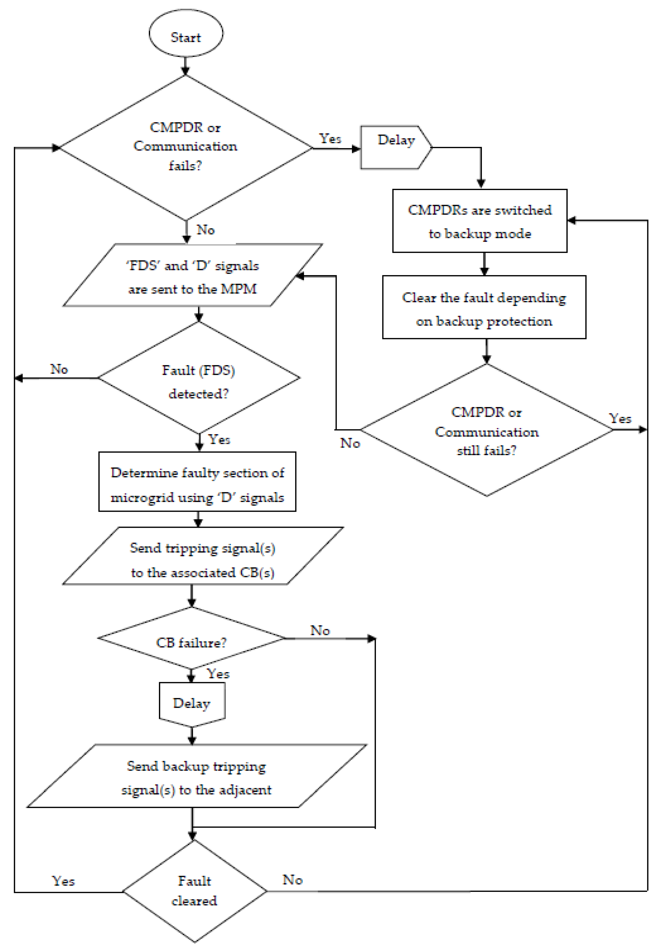
According to the proposed protection strategy, a possible minimum part of the microgrid is isolated due a fault from the rest of the microgrid via the instructions sent to one or more CMPDRs. The number of CMPDRs that are employed in the microgrid is decided based on the desired selectivity and reliability requirements. Each CMPDR, which concerns protecting a specific device or zone, sends two signals to the microgrid protection manager (MPM): (1) the fault detection signal (FDS) that determines whether the CMPDR has detected a fault inside its territory and (2) the fault direction signal (D), which shows the fault direction from the CMPDR viewpoint. The FDS and D signals derivations are discussed in Section 2.1, Section 2.2, Section 2.3, respectively. The MPM gets the FDS and D signals from each CMPDR and determines, by an appropriate logical computation, the fault impacted section of the microgrid. The logic computation is identical to that of the “directional judgment” protection method. Figure 2 shows the flowchart of the proposed protection strategy.
Once the incidence of a fault is determined (by employing the FDS signals), the MPM waits for a predetermined time to get new directional signals and judge the faulty section of the microgrid. Then, suitable tripping signal(s) are commanded to the circuit breaker(s) corresponding to the CMPDR(s), to open and isolate the affected section of the microgrid. The tripping signals are commanded after a time delay (longer than 0.1 s, but shorter than 0.15 s [31]) to allow the downstream protection devices to act first. This definite-time margin is able to assure coordination of the CMPDRs with the main protection downstream devices.
On the other hand, to assure that all CMPDRs sufficiently allow their downstream protection devices to act, one can use different time delays for the CMPDRs in the program deployed into the MPM.
When there is a failure of circuit breaker, a failure signal is dispatched to the nearby circuit breakers so that the minimum possible part of the microgrid is isolated. The circuit breaker failure signal is dispatched following a time delay (longer than 0.3 s, but shorter than 0.4 s [31]) if any of the FDSs is still energized.
The backup protection scheme is activated following about 0.4 s from the fault occurrence and, hence, offers the possibility for the above mentioned two signals to be dispatched. Consequently, if the communication system fails and the CMPDRs do not get any signal for a while, all CMPDRs will be automatically transferred to the backup protection scheme. Communication is not required for backup protection; however, in contrast to the main protection, the backup protection takes comparatively longer to act.
The part of the microgrid which has been isolated due to a fault incident can be reconnected and resynchronized to the rest of the microgrid network via the resynchronization scheme of its DGs, and the reclosing capability of its circuit breakers, provided that the fault is temporary and cleared following the isolation.
The proposed protection strategy can be implemented by employing the smart grid’s communication capabilities. With the advent of the recent communication technology, standardized wireless communication is available for personal area, local area, metropolitan area, and wide area networks. Wireless communications have many benefits such as less installation cost, faster deployment, and higher mobility in contrast to wired communications [32]. The IEEE-802.11-based wireless LAN protocol [33] combined with long-distance wireless Ethernet bridges [34] can be a possible communication means for the presented protection strategy. Wireless signal transmissions need less than 0.1 ms overall processing time for distances of less than 30 km, which is sufficient for microgrid applications. The IEC developed communication protocol IEC 61850 is another possible communication medium for the proposed protection strategy.
It should be noted that an auto reclosing function can be added to the proposed protection strategy. For this purpose, once the MPM detects a fault in some part of the microgrid network, it will instantly command trip signals to the associated CMPDR(s), to isolate the faulty part of the network immediately. Tripping signals are also commanded simultaneously to the DGs installed in the fault affected part of the network to cut off them. Hence, none of the DGs are connected to the fault affected part of the network when the CMPDR recloses the circuit following the reclosing dead time. Auto-reclosing and resynchronization are only possible if the fault is temporary and immediately cleared after the isolation of the faulty part. A perfect coordination between the microgrid protection system and stability control and load management systems is also very important for this purpose.
The backup protection scheme is activated following about 0.4 s from the fault occurrence and, hence, offers the possibility for the above mentioned two signals to be dispatched. Consequently, if the communication system fails and the CMPDRs do not get any signal for a while, all CMPDRs will be automatically transferred to the backup protection scheme. Communication is not required for backup protection; however, in contrast to the main protection, the backup protection takes a comparatively longer time to act.
4. Case Study and Simulation Results
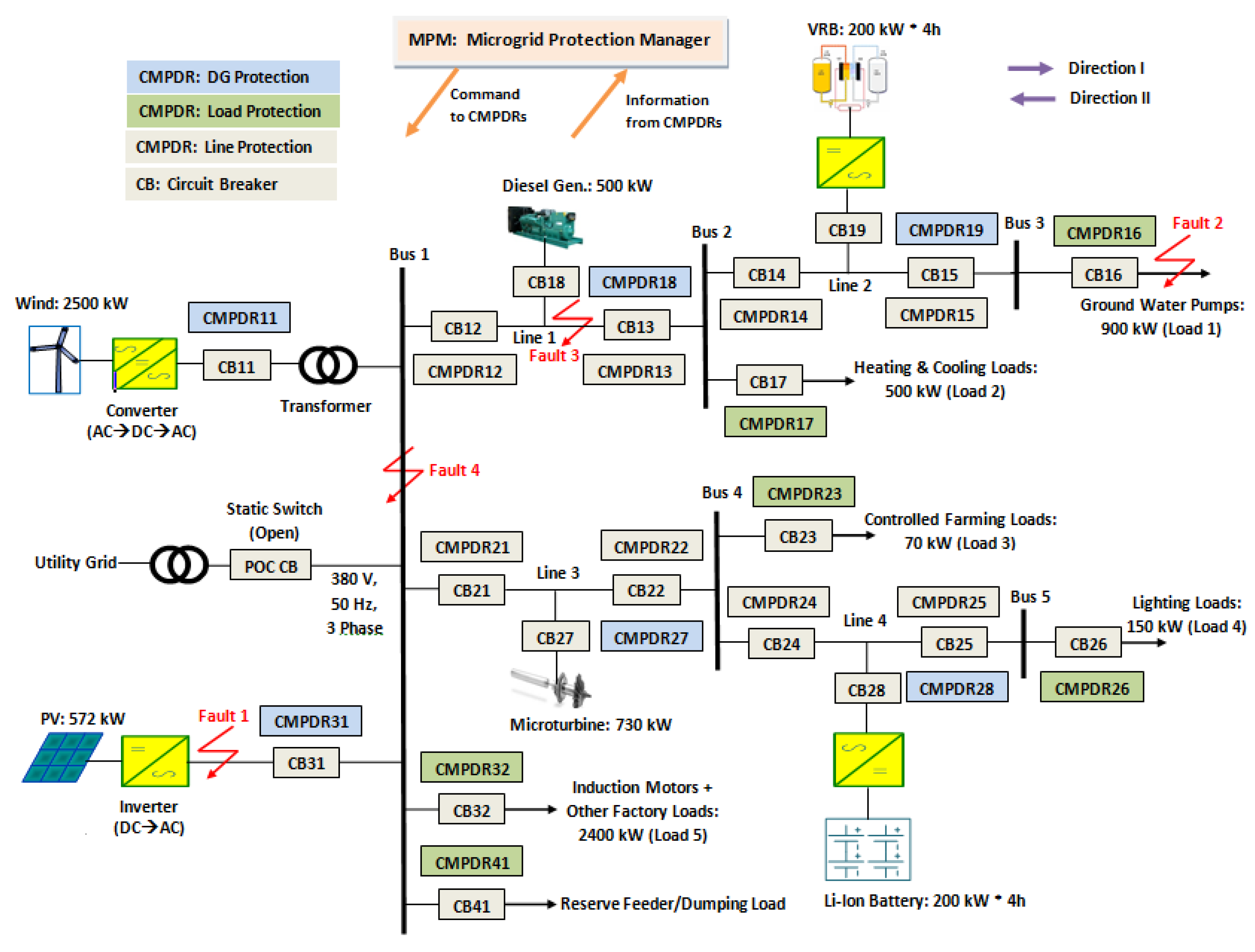
To demonstrate its applicability, the proposed protection strategy is presented to and discussed under the framework of the microgrid of Figure 3. The microgrid of Figure 3 is a realistic operational industrial microgrid (Goldwind Smart Microgrid System), in Beijing, China. The microgrid network supplies the energy demands of an industrial park (Goldwind Science and Technology. Co., Ltd., Beijing, China) with an aggregate peak capacity of 4MVA.
As shown in Figure 3, the islanded microgrid contains five power electronics converter-interfaced DGs (PEC-DGs) and one synchronous machine-based DGs (SM-DGs). The PEC-DGs are of the photovoltaic, wind, microturbine and energy storage (two batteries: vanadium redox flow battery (VRB) and lithium-ion (Li-Ion) battery) types, and can supply a maximum total power of 4202 kW; the PEC-DGs type and rated capacity are shown in Figure 3. A maximum aggregate power of 500 kW is also supplied by the SM-DG (diesel generator); the type and rated capacity of the SM-DG is also indicated in Figure 3. The wind energy based DG is coupled with the network via Δ/GY (delta/grounded wye) transformer. Henceforth, the islanded microgrid of Figure 3 is said to be the “case study microgrid.”
Table 2 summarizes characteristics and values of the parameters of the components of the case study microgrid system.
A dual control mode has been employed to regulate the network voltage and frequency in this paper. The renewable sources (wind and PV) should always operate in PQ control mode to extract the maximum possible power from these sources. However, either the energy storage batteries or SM-DGs should be able to operate in U/f control mode to set the voltage and frequency reference values of the islanded microgrid system. The choice of DGs for the U/f operation mode is based on the power capacity of the DGs, and required power mismatch to stabilize the voltage and frequency of the microgrid network. The details of the control strategies of the DGs for microgrid operation can be found in [35].
As described in Section 2, each CMPDR dispatches two signals, the FDS and D signals, to the MPM. The MPM protection algorithm investigates the signal information sent by all CMPDRs and finds out the exact fault location. Subsequently, the tripping signal(s) will be commanded to the associated circuit breaker(s) to isolate the faulty part of the microgrid network after a predetermined time delay. Table 3 presents the CMPDRs that are employed for the main and backup protections to detect and isolate faults within the case study microgrid. When fault impacts the microgrid network, the D and FDS signals of the responsible CMPDR(s) will be sent to the MPM. A fault is taken as a forward fault when both FDS and D signals are unity.
To validate the effectiveness of the proposed islanded microgrid protection scheme and its relay, the case study islanded microgrid, shown in Figure 3, has been modeled and simulated in the PSCAD/EMTDC software environment [36]. For the fault protection simulation, the CMPDR/MPDR settings and delay times have been determined based on the IEEE recommended practices for protection of industrial power systems [31]. For CMPDRs in the main protection, the delay time is assumed to be 100 ms. This gives enough time for the CMPDR Park-transformed disturbance voltage detection based protection module not to send solid fault detection signal to the tripping module, due to short-duration incidence of voltage sags in the microgrid network. The delay time of CMPDRs/MPDRs for the backup protection is taken as 400 ms from the fault occurrence to offer a possibility to the downstream protection devices (such as fuses) to act first and send breaker trip failure signal to nearby breakers if there is failure of main circuit breaker(s). It requires 20 ms for the breakers to open or close. The CMPDRs are configured with dual setting directional elements, and thus can offer both main and backup protections whenever necessary.
Similarly, the reverse delay times of CMPDRs are set based on common practices and the methods presented in Zamani et al. [13], and may have different values from the forward delay times as there can be different configuration of DGs and loads in the reverse direction. The q-axis reference voltage and threshold disturbance voltage settings of the CMPDRs in this paper have been set with reasonable values based on common practices. The q-axis reference voltage is assumed to be the q-axis nominal voltage. The threshold disturbance voltage is assumed to be 50% of the nominal voltage for double-phase-to-ground (DLG), three-phase-to-ground (3LG) and phase-to-phase (LL) faults, while a threshold of 20% of the nominal voltage has been assumed for single-phase-to-ground (LG) faults.
The paper employed the Daubechies D-8 (denoted as Db8) wavelet, since it has been verified to perform accurately and to meet the aforementioned conditions of the HIF detection module. The DWT sampling frequency was taken as 6 kHz, and the MRA filter banks resolution level was taken as unity.
The simulations contain faults at different locations of the case study microgrid; Fault 1, Fault 2, Fault 3, and Fault 4 (shown in Figure 3) that represent faults on the DG, load, transmission line, and busbar, respectively. All faults types (LG, DLG, LL, 3LG faults, and HIFs) have been included. HIFs are simulated in this paper based on the technique discussed in [11]. Most studies have used a 40 Ω resistance, as the largest reasonable value of resistance, between the ground and a fallen electric conductor. This value is also used by several utilities [37]. In this paper, however, an 80 Ω resistance has been used for HIFs, to simulate a further serious condition.
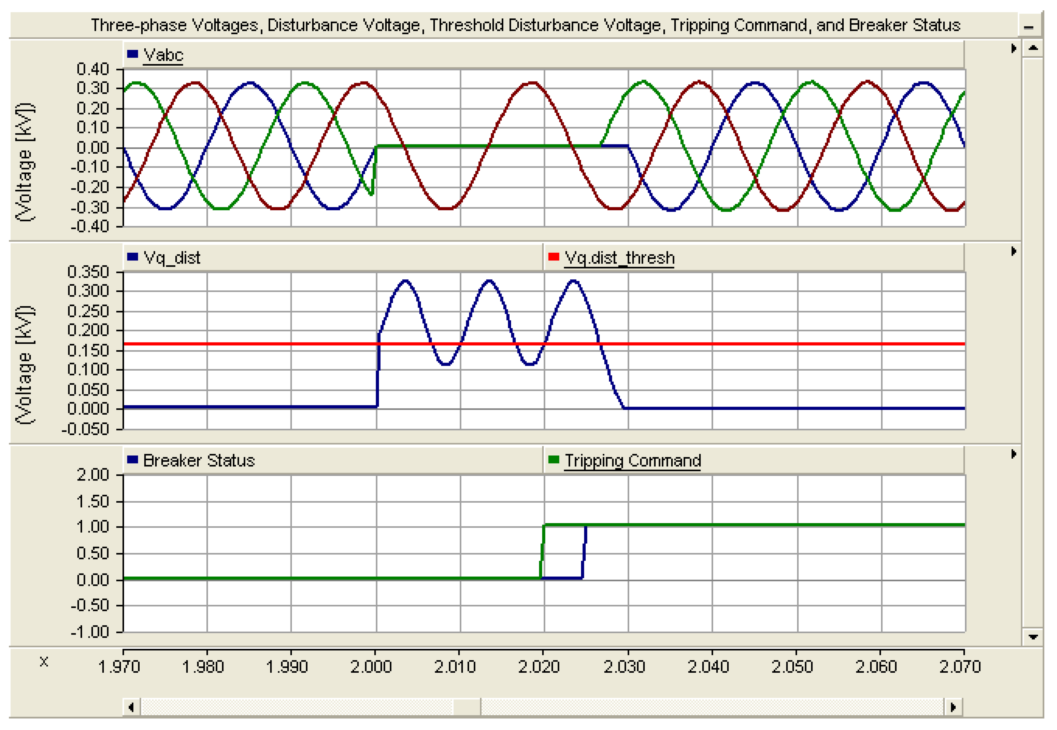
For DG (PV), the main protection is offered by CMPDR31 when Fault 1 (very close to the PV terminal) occurs. Figure 4 shows the three phase voltages and Park-transformed disturbance voltage measured at circuit breaker (CB) 31 (at the pole connected to the PV side), when Fault 1 (3LG) happens. From the results, it can be observed that the disturbance voltage changes significantly when the fault has occurred, and exceeds the specified threshold value. It is shown that the disturbance voltage is a pure DC component, constant, when 3LG fault happens. For possible PSCAD close-up view of the pre-fault, on-fault, and post-fault conditions using a single curve, the relay time delays and the breaker action times are slightly changed from the time setting values discussed in Section 3, for simulation purpose. As shown in Figure 4, the fault has occurred at 2 s and stayed for 0.05 s. The CMPDR has detected the fault based on the significant change in the value of the disturbance voltage, and has issued a tripping signal at 2.02 s. The CB has opened at 2.025 s to disconnect the PV and isolate it from the rest of the microgrid network. The fault has cleared/disappeared at 2.05 s and the circuit breaker has reclosed at 2.07 s. This auto-reclosing action of the proposed protection strategy is very important to circumvent generation power insufficiency, due to DG outages under impermanent fault circumstances in the islanded microgrid. As seen in Figure 4, the microgrid network voltage has regained its steady-state operating value immediately after the clearance of the fault by the reclosing action of the proposed relay. This shows the rapidness capability of the proposed protection strategy and its fast communication ability with the stability control and load management systems of the microgrid.
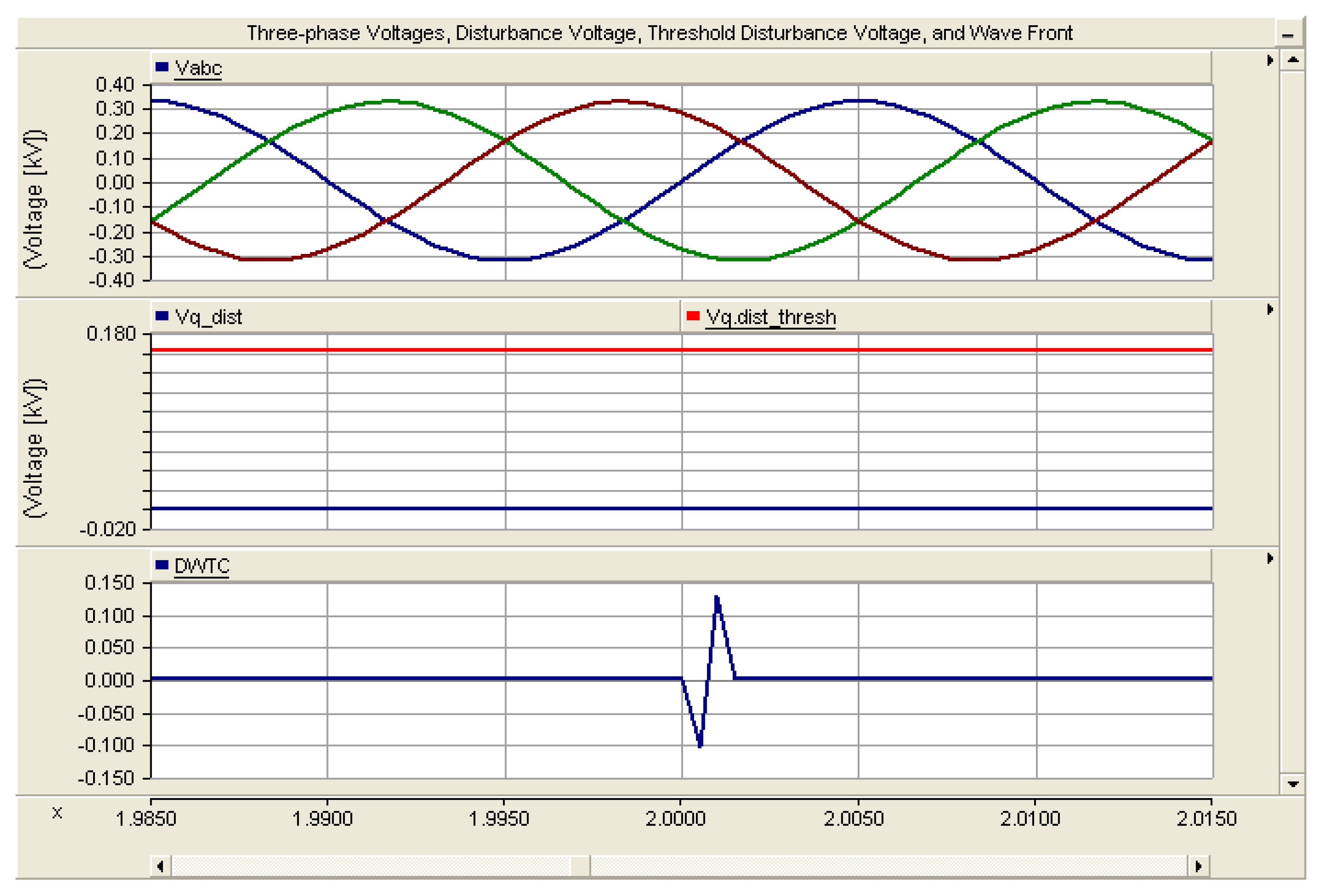
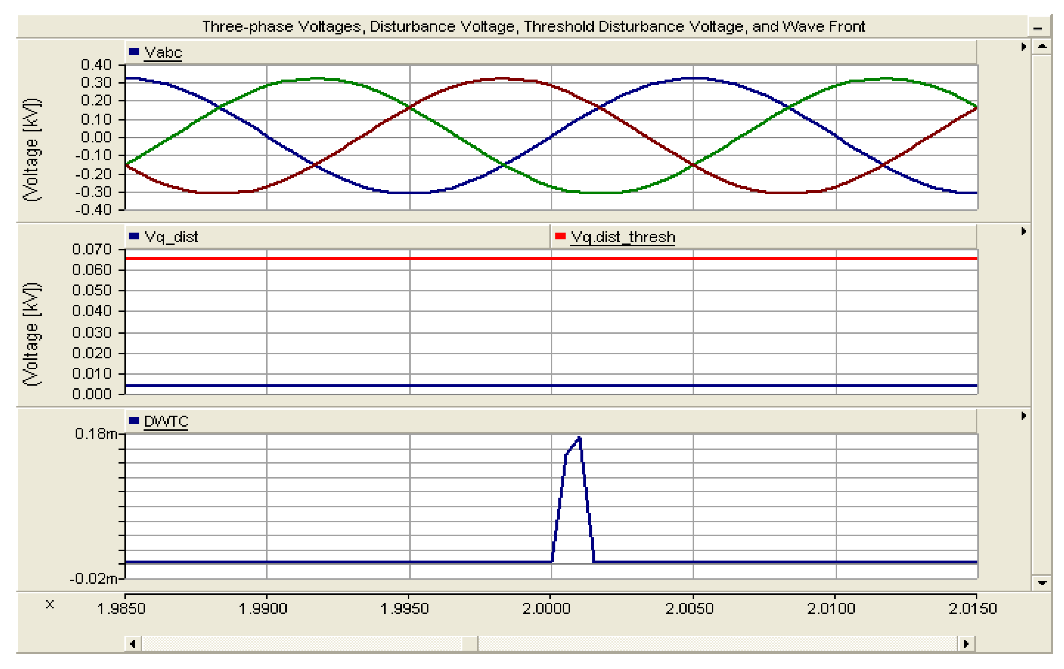
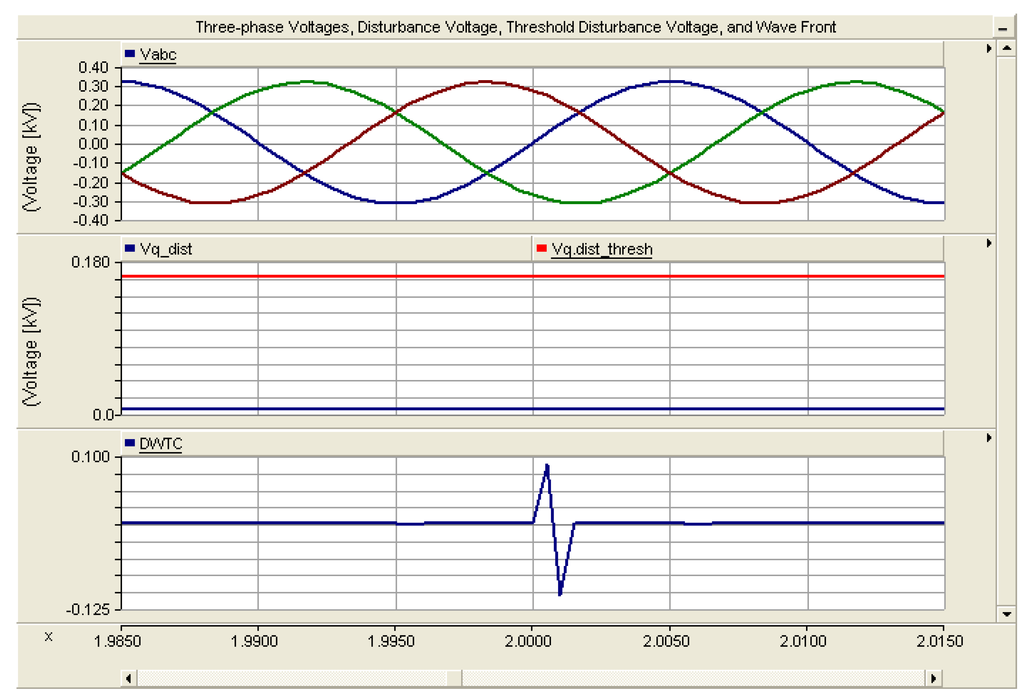
Figure 5 shows the three phase voltages, disturbance voltage, and DWTC (wave front) of current transients measured at CB31, when Fault 1 (3LG HIF) happens. From the results, it can be seen that the disturbance voltage changed slightly when the 3LG HIF has occurred. It is less than the specified threshold value. Thus, this Park-transformed disturbance voltage is not adequate to actuate the CMPDR and trip the corresponding CB. However, the DWTC has shown a significant change (exceeds the zero threshold value) when the 3LG HIF has occurred. The fault has occurred at 2 s. The CMPDR has detected the fault based on the significant change in the value of the DWTC. A tripping signal is issued at 2.02 s, and the CB has opened at 2.025 s to disconnect the PV and isolate it from the rest of the microgrid network. The fault has cleared/disappeared at 2.05 s and the CB has reclosed at 2.07 s.
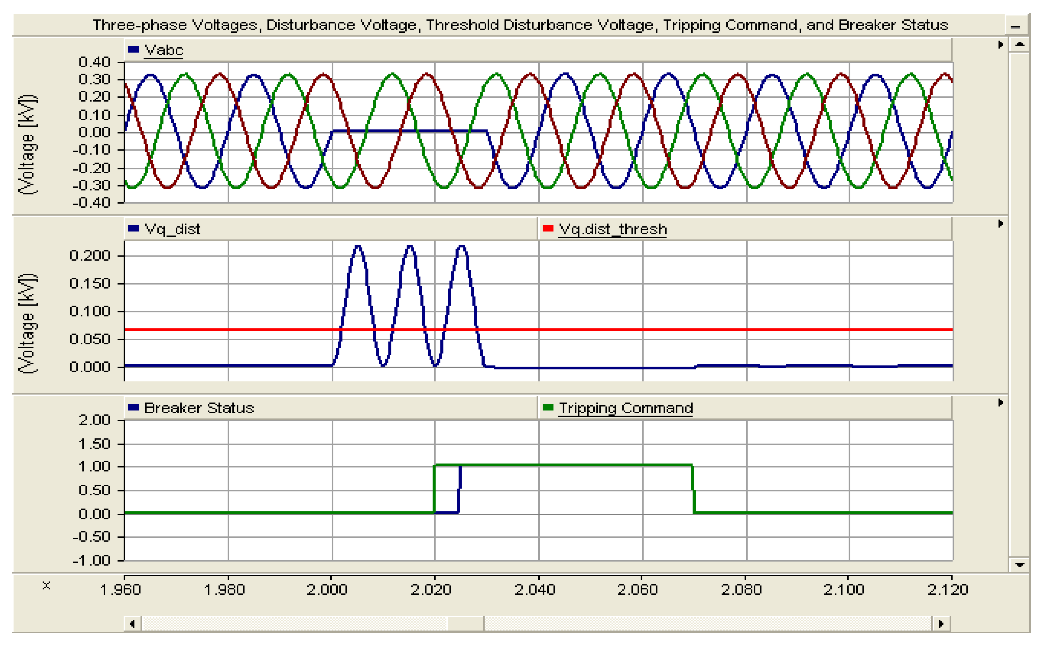
For Load 1 feeder, in the direction I the main protection is offered by CMPDR16 and backup protection by CMPDR15 when Fault 2 occurs. Figure 6 shows the three phase voltages and disturbance voltage measured at CB16 (at the pole connected to Bus3), when Fault 2 (DLG) occurs. From the result, it can be seen that the disturbance voltage changes considerably when the fault has occurred, and exceeds the specified threshold value. It is shown that the disturbance voltage is a DC voltage plus an oscillating voltage component with twice of the fundamental frequency when DLG fault happens. In this case, the fault has occurred at 2 s. The CMPDR has detected the fault and issued tripping signal at 2.02 s, and the CB has opened at 2.025 s to disconnect Load 1 and isolate it from the rest of the microgrid network. The fault persists (not temporary) and the reclosing action is not successful.
As mentioned in Section 3, the MPM of proposed protection strategy has the capability to communicate with the microgrid stability control and load management systems. In this paper, Faults 2 is simulated as permanent fault to illustrate the interaction/coordination between the proposed protection system with the stability control and load management systems of the microgrid. In this case, Faults 2 persists in the whole simulation period.
The MPM still receives a fault detection signal from CMPDR16 though CB16 has been opened. Hence, the MPM knows that Fault 2 is permanent (it persists) and the auto-reclosing action is not issued to CB16, since auto-reclosing and resynchronization are only possible if the fault is temporary and immediately cleared after the isolation of the faulty part. The MPM then sends information to the microgrid stability control and load management systems to inform it that Load 1 has been dropped-off. The stability control system then adjusts the generation power level(s) of the DG(s) (i.e., either the power output magnitude of the diesel generator, microturbine, VRB, Li-ion battery or a combination of them) by the corresponding amount of power of the dropped-off load. Instead of the stability control system action, the load management system could either switch on the dumping load by an equal amount of Load 1’s power to compensate the power unbalance resulting from Load 1 outage. It could also be done by a combined action of both the stability control and load management systems. These all actions are performed based on the operation strategy of the microgrid stability control and load management systems, in real-time following the received information from the MPM.
Figure 7 shows the three phase voltages, disturbance voltage, and DWTC of current transients measured at CB16, when Fault 2 (DLG HIF) happens. From the results, it can be seen that the DWTC has shown a significant change (exceeds the zero threshold value) when the DLG HIF has occurred. The fault incident and clearing time properties are similar with the DLG solid fault discussed above, and the same conclusions can be drawn except the Park-transformed disturbance voltage in this case is not the fault detection signal.
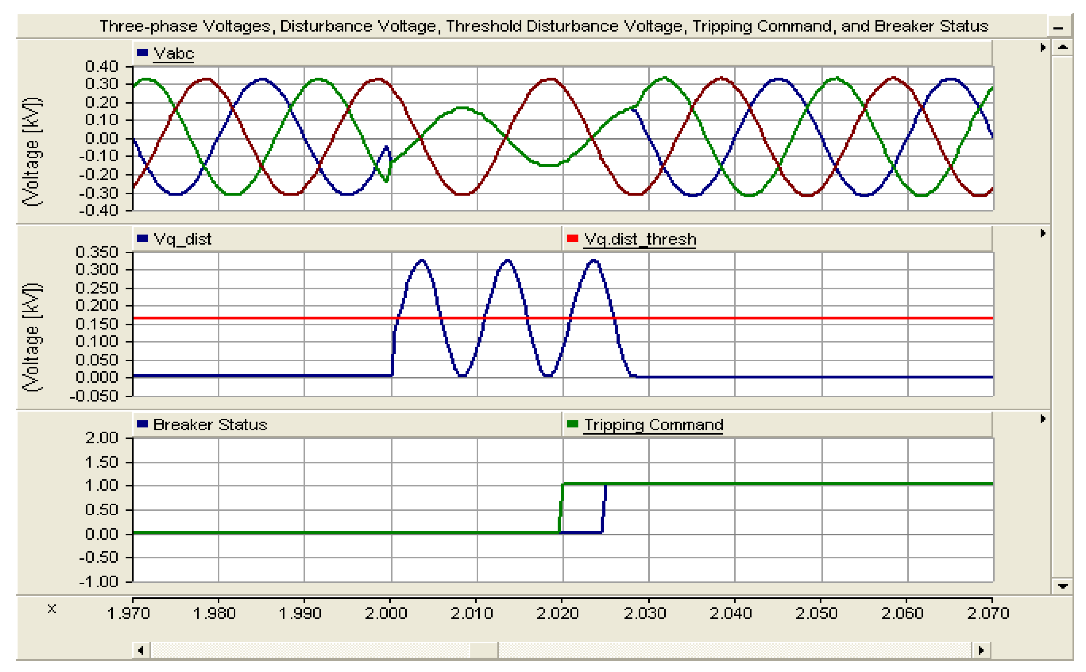
CMPDR12 in direction I and CMPDR13 in direction II are responsible for main protection of Line 1 when Fault 3 occurs. CMPDR21 for CMPDR12 and CMPDR14 for CMPDR13 are the associated backup protections in direction II. Figure 8 shows the three phase voltages and disturbance voltage measured at CB13 (at the pole connected to Bus2), when Fault 3 (LG) occurs. The same result can also be obtained at CB12 (at the pole connected to Bus1). From this result, it can be observed that the disturbance voltage changes significantly when the fault has occurred, and exceeds the specified threshold value. It is shown that the disturbance voltage is a DC voltage plus an oscillating voltage component with twice of the fundamental frequency when LG fault happens. The fault has occurred at 2 s and stayed for 0.05 s. Both CMPDRs have detected the fault and issued tripping signals at 2.02 s. The CBs have opened at 2.025 s to disconnect Line 1and isolate it from the rest of the microgrid network. The fault has disappeared at 2.05 s and the circuit breakers have reclosed at 2.07 s.
Figure 9 shows the three phase voltages, disturbance voltage, and DWTC of current transients measured at CB13, when Fault 3 (LG HIF) happens. The same result can also be obtained at CB12. From the results, it can be seen that the DWTC exceeds the zero threshold value when the LG HIF has occurred. The fault incident and clearing time properties are similar to the LG solid fault discussed above, and the same conclusions can be outlined, except the Park-transformed disturbance voltage in this case is not the fault detection signal.
CMPDR12, CMPDR21, CMPDR32, and CMPDR41 are responsible for main protection of Bus 1 when Fault 4 occurs. Here, the protection schemes of these relays, in direction II, are no more backup protection for nearby lines; instead, they operate as instantaneous main protection for Bus 1. The MPM identifies a bus fault based on the received directional signals from all the CMPDRs connected with the bus in the same group. In the event of Fault 4, the wind DG protection, CMPDR11, and the PV DG protection, CMPDR31, also operate to protect the respective DGs, not to contribute for the bus fault current.
The MPM determines the occurrences of a bus fault if all the directional signals (Ds) received from all the relays connected with the bus are minus unity (−1). Then, tripping signals will be issued to all the circuit breakers associated with these relays. Figure 10 shows the three phase voltages and disturbance voltage measured at CB21 (at the pole connected to Bus1), when Fault 4 (LL) occurs. The same results can also be obtained at CB12, CB32 and CB41 (at the poles connected to Bus1). From these results, it can be seen that the disturbance voltage changes considerably when the fault has occurred, and exceeds the specified threshold value. It is shown that the disturbance voltage is a DC voltage plus an oscillating voltage component with twice of the fundamental frequency when an LL fault occurs. In this case, the fault has occurred at 2 s. The CMPDRs have detected the fault and issued tripping signals at 2.02 s. The CBs have opened at 2.025 s to disconnect Bus 1 and isolate it from the rest of the microgrid network. The fault persists and the reclosing action is not successful.
Here, as with the case of Fault 2 discussed above, Fault 4 is also simulated as a permanent fault to illustrate the interaction/coordination between the proposed protection system with the stability control and load management systems of the microgrid. Fault 4 persists in the whole simulation period. The MPM still receives fault detection signals from CMPDR11, CMPDR12, CMPDR21, CMPDR31, CMPDR32, and CMPDR41 though CB11, CB12, CB21, CB31, CB32 and CB41 have been opened. Hence, the MPM knows that Fault 4 unfortunately persists and the auto-reclosing actions are not issued to CB11, CB12, CB21, CB31, CB32 and CB41. The MPM then sends information to the microgrid stability control and load management systems to inform the wind DG, PV DG, Load 5 and reserve feeder/dumping load are dropped-off. The stability control system then adjusts the generation power level(s) of the DG(s) (i.e., either the power output magnitude of the diesel generator, microturbine, VRB, Li-ion battery or a combination of them) by the corresponding amount of power of the dropped-off DGs and load. Instead of the stability control system action, the load management system could either shed some of the non-critical loads by an equal amount of the dropped-off DGs’ and load’s power to compensate the power unbalance resulted from the DGs and Load 5 outages. It could also be done by a combined action of both the stability control and load management systems. These all actions are performed based on the operation strategy of the microgrid stability control and load management systems in real-time following the received information from the MPM.
Figure 11 shows the three phase voltages, disturbance voltage, and DWTC of current transients measured at CB21, when Fault 4 (LL HIF) happens. The same result can also be obtained at CB12, CB32 and CB41. From the results, it can be seen that the DWTC exceeds the zero threshold value when the LL HIF has occurred. The fault incident and clearing time properties are similar with the LL solid fault discussed above and the same conclusions can be outlined except the Park-transformed disturbance voltage in this case is not the fault detection signal.
5. Conclusions
This paper proposed a new communication-supported strategy for fast and reliable protection of converter-interfaced islanded microgrids. The strategy uses the Park-transformed system voltage and wavelet coefficients of modal current transients to detect the occurrences of solid and high-impedance faults respectively. The strategy addresses the problems caused by the small-magnitude in potential fault currents associated with islanded operation of power electronics dominated microgrids. It has been demonstrated that the strategy provides an alternative means of protection to the traditional overcurrent protection for scenarios, which contribute to small fault currents. A backup protection scheme was also presented to deal with malfunction of the main protection devices and failure of the communication medium. The primary and secondary protection algorithms can be integrated into commercially accessible digital relays with directional modules. The proposed microgrid protection digital relay which enables the proposed protection strategy comprises five modules, namely, directional, Park-transformed disturbance voltage detection, HIF detection, tripping, and auto-reclosing modules. The relay can distinguish between the different types of fault from the characteristics of the Park-transformed disturbance voltage. The strategy does not need adaptive components. Above all, it is effective regardless of the location, size, and type of the microgrid DGs. It is also effective for any fault current magnitudes, fault impedances, and fault types and locations. Several simulations were conducted using PSCAD/EMTDC software environment for different case studies and fault scenarios, to prove the effectiveness of the presented strategy and its digital relay.
Author Contributions
Dehua Zheng and Abinet Tesfaye Eseye modeled the microgrid system, designed and implemented the protection algorithm, and simulated the microgrid system with the embedded relays; Jianhua Zhang performed the supervision, professional advices and continuous follow up for the successful completion of the work; all authors have read and approved the final manuscript.
Acknowledgments
This work is supported financially and technically by the Microgrid Research Group of Goldwind Science and Technology Co., Ltd., and the School of Electrical & Electronic Engineering of North China Electric Power University, and the Faculty of Engineering & Technology of Mettu University.
Conflicts of Interest
The authors declare no conflict of interest.
List of Symbols and Abbreviations
| DG | distributed generator |
| PSCAD | power system computer-aided design |
| EMTDC | electro-magnetic transient including direct current |
| HIF | high impedance fault |
| dq | d-axis ~ q-axis reference frame |
| ESS | electrical energy storage |
| 50/51 | conventional overcurrent relay |
| MPDR | microgrid protection digital relay |
| CMPDR | communication-supported microgrid protection digital relay |
| abc | three phase reference frame |
| αβ | alpha-beta reference frame |
| MRA | multi-resolution analysis |
| DWT | discrete wavelet transform |
| PT | potential transformer |
| Va, Vb and Vc | phase a, b and c voltages, respectively |
| Vα and Vβ | alpha and beta axis voltages, respectively |
| Vd and Vq | d-axis and q-axis voltages, respectively |
| Vq.dist | disturbance voltage signal |
| Vq.ref | q-axis reference voltage |
| Vm | peak phase voltage |
| n | harmonic order |
| ω | angular frequency of system voltage |
| f | frequency |
| ϕ | initial phase angle of the system voltage |
| ωr | angular frequency of the stator voltages |
| θ | rotor angle of rotation |
| DC | direct current |
| V0 | zero-sequence voltage |
| V’a, V’b and V’c | three phase voltage for a, b, and c phases, excluding zero sequence component |
| VPm and VNm | peak values of the positive- and negative-sequence fundamental voltages |
| ϕP and ϕN | initial phase angle values of the positive- and negative-sequence voltages |
| SFDS | solid fault detection signal |
| DWTC | discrete wavelet transform coefficient |
| HIFDS | high impedance fault detection signal |
| FDS | fault detection signal |
| D | main directional signal |
| D0, D2, D1 | zero-, negative-, and positive-sequence directional signals, respectively |
| CB | circuit breaker |
| MPM | microgrid protection manager |
| LAN | local area network |
| IEEE | institute of electrical and electronic engineers |
| IEC | international electro-technical commission |
| MVA | mega volt ampere |
| PEC-DG | power electronics converter-interfaced DG |
| SM-DG | synchronous machine-based DG |
| VRB | vanadium redox flow battery |
| Li-Ion | lithium-ion |
| Δ/GY | delta/grounded wye |
| PQ | active-reactive power |
| U/f | voltage/frequency |
| PV | photovoltaic |
| ms | milli second |
| LG | single-phase-to-ground |
| DLG | double-phase-to-ground |
| LL | phase-to-phase |
| 3LG | three-phase-to-ground |
| Db8 | Daubechies 8 wavelet |
| kHz | killo herz |
| Ω | ohm |
| s | second |
| Vq.dist_thresh | threshold disturbance voltage signal |
| Vabc | three phase voltages |
| Iabc | three phase currents |
| V012 | zero-, positive-, and negative-sequence voltages |
| I012 | zero-, positive-, and negative-sequence currents |
| Vd.ref | d-axis reference voltage |
| Iα | alpha-axis current |
| Iβ | beta-axis current |
| I0 | zero current |
| DWT Iα | discrete wavelet transform of alpha-axis current |
| DWT Iβ | discrete wavelet transform of beta-axis current |
| DWTI0 | discrete wavelet transform of zero current |
| Max | maximum |
| Vabc_healthy | three phase voltages of non-fault-impacted or healthy section |
| Δ|V| | voltage magnitude deviation |
| Δf | frequency deviation |
| Δθ | phase angle deviation |
| 25 | synchronism-check Element |
| 67 | directional relay |
References
- Katiraei, F.; Iravani, M.R.; Lehn, W. Micro-grid Autonomous Operation During and Subsequent to Islanding Process. IEEE Trans. Power Deliv. 2005, 20, 248–257. [Google Scholar] [CrossRef]
- Lasseter, R.H. Microgrids. In Proceedings of the Power Engineering Society Winter Meeting, New York, NY, USA, 27–31 January 2002; Volume 1, pp. 305–308. [Google Scholar]
- Han, L.; Abinet, T.E.; Jianhua, Z.; Zheng, D. Optimal Energy Management for Industrial Microgrids with High-penetration Renewables. Prot. Control Mod. Power Syst. 2017, 2, 12. [Google Scholar] [CrossRef]
- Di Manno, M.; Varilone, P.; Verde, P.; de Santis, M.; di Perna, C.; Salemme, M. User friendly smart distributed measurement system for monitoring and assessing the electrical power quality. In Proceedings of the 2015 AEIT International Annual Conference (AEIT), Naples, Italy, 14–16 October 2015; pp. 1–5. [Google Scholar] [CrossRef]
- Walling, R.A.; Saint, R.; Dugan, R.C.; Burke, J.; Kojovic, L.A. Summary of Distributed Resources Impact on Power Delivery Systems. IEEE Trans. Power Deliv. 2008, 23, 1636–1644. [Google Scholar] [CrossRef]
- Butler-Purry, K.L.; Funmilayo, H.B. Overcurrent Protection Issues for Radial Distribution Systems with Distributed Generators. In Proceedings of the Power & Energy Society General Meeting, Calgary, AB, Canada, 26–30 July 2009; pp. 1–5. [Google Scholar] [CrossRef]
- Dewadasa, M.; Ghosh, A.; Ledwitch, G.; Wishart, M. Fault Isolation in Distributed Generation Connected Distribution Networks. IET J. Gener. Transm. Distrib. 2011, 5, 1053–1061. [Google Scholar] [CrossRef] [Green Version]
- Nikkhajoei, H.; Lasseter, R. Microgrid Protection. In Proceedings of the Power Engineering Society General Meeting, Tampa, FL, USA, 24–28 June 2007; pp. 1–6. [Google Scholar]
- Tumilty, R.M.; Brucoli, M.; Green, T.C. Approaches to Network Protection for Inverter Dominated Electrical Distribution Systems. In Proceedings of the 3rd IET International Conference on Power Electronics, Machines and Drives, Dublin, Ireland, 4–6 April 2006; pp. 622–626. [Google Scholar]
- Al-Nasseri, H.; Redfern, M.; Li, F. A Voltage Based Protection for Micro-grids Containing Power Electronic Converters. In Proceedings of the IEEE Power Engineering Society General Meeting, Montreal, QC, Canada, 18–22 June 2006; pp. 1–7. [Google Scholar]
- Sortomme, E.; Venkata, S.S.; Mitra, J. Microgrid Protection Using Communication-assisted Digital Relays. IEEE Trans. Power Deliv. 2010, 25, 2789–2796. [Google Scholar] [CrossRef]
- Jayawarna, N.; Jones, C.; Barnes, M.; Jenkins, N. Operating Micro-Grid Energy Storage Control during Network Faults. In Proceedings of the IEEE International Conference on System of Systems Engineering, San Antonio, TX, USA, 16–18 April 2007; pp. 1–7. [Google Scholar]
- Zamani, M.A.; Sidhu, T.S.; Yazdani, A. A Protection Strategy and Microprocessor-based Relay for Low-voltage Microgrids. IEEE Trans. Power Deliv. 2011, 26, 1873–1883. [Google Scholar] [CrossRef]
- Wan, H.; Li, K.K.; Wong, K.P. An Adaptive Multiagent Approach to Protection Relay Coordination with Distributed Generators in Industrial Power Distribution System. IEEE Trans. Ind. Appl. 2010, 46, 2118–2124. [Google Scholar] [CrossRef]
- Perera, N.; Rajapakse, A.D.; Buchholzer, T.E. Isolation of Faults in Distribution Networks with Distributed Generators. IEEE Trans. Power Deliv. 2008, 23, 2347–2355. [Google Scholar] [CrossRef]
- Li, B.; Li, Y.; Bo, Z.; Kilmek, A. Design of Protection and Control Scheme for Microgrid Systems. In Proceedings of the 44th International University Power Engineering Conference, Glasgow, UK, 1–4 September 2009; pp. 1–5. [Google Scholar]
- Zamani, M.A.; Sidhu, T.S.; Yazdani, A. A Strategy for Protection Coordination in Radial Distribution Networks with Distributed Generators. In Proceedings of the IEEE Power and Energy Society General Meeting, Providence, RI, USA, 25–29 July 2010; pp. 1–8. [Google Scholar]
- Hou, C.; Hu, X. A Study of Voltage Detection Based Fault Judgment Method in Micro-grid with Inverter Interfaced Power Source. In Proceedings of the 2009 6th International Conference on Electrical Engineering, Shenyang, China, 6–9 May 2009; pp. 1–5. [Google Scholar]
- Zamani, M.A.; Yazdani, A.; Sidhu, T.S. A Communication-assisted Protection Strategy for Inverter-based Medium-voltage Microgrids. IEEE Trans. Smart Grid 2012, 3, 2088–2099. [Google Scholar] [CrossRef]
- De Santis, M.; Noce, C.; Varilone, P.; Verde, P. Analysis of the origin of measured voltage sags in interconnected networks. Electr. Power Syst. Res. 2018, 154, 391–400. [Google Scholar] [CrossRef]
- Lai, K.; Illindala, M.S.; Haj-ahmed, M.A. Comprehensive Protection Strategy for an Islanded Microgrid Using Intelligent Relays. In Proceedings of the IEEE Industry Applications Society Annual Meeting, Addison, TX, USA, 18-22 October 2015; pp. 1–11. [Google Scholar]
- Kexing, L.; Illindala, M.S.; Haj-ahmed, M.A. Comprehensive Protection Strategy for an Islanded Microgrid Using Intelligent Relays. IEEE Trans. Ind. Appl. 2017, 53, 47–55. [Google Scholar]
- Clarke, E. Circuit Analysis of AC Power Systems; Wiley: New York, NY, USA, 1950; Volume 1, p. 81. [Google Scholar]
- Park, R. Two-reaction Theory of Synchronous Machines: Generalized Method of Analysis—Part I. Trans. AIEE 1929, 48, 716–727. [Google Scholar]
- Christie, R.C.; Zadehgol, H.; Habib, M.M. High Impedance Fault Detection in Low Voltage Networks. IEEE Trans. Power Deliv. 1993, 8, 1829–1836. [Google Scholar] [CrossRef]
- Aucoin, B.M.; Russell, B.D. Distribution High Impedance Fault Detection Utilizing High Frequency Current Components. IEEE Trans. Power Appl. Syst. 1982, PAS-101, 1596–1606. [Google Scholar] [CrossRef]
- Jeerings, D.I.; Linders, J.R. Unique Aspects of Distribution System Harmonics due to High Impedance Ground Faults. IEEE Trans. Power Deliv. 1990, 5, 1086–1094. [Google Scholar] [CrossRef]
- Perera, N.; Rajapakse, A.D.; Muthumuni, D. Wavelet Based Transient Directional Method for Busbar Protection. In Proceedings of the International Conference on Power Systems Transients (IPST2011), Delft, The Netherlands, 14–17 June 2011. [Google Scholar]
- Meyer, B. Directional Ground and Sensitive Ground Fault Settings. Cooper Power Syst. Cooper Ind. 2004, 1–17. Available online: http://studylib.net/doc/13718297/directional-ground-and-sensitive-ground-fault-settings--r (accessed on 23 May 2017).
- Zeineldin, H.H.; Sharaf, H.M.; Ibrahim, D.K.; Abou EI-Zahab, E.E.D. Optimal Protection Coordination for Meshed Distribution Systems with DG Using Dual Setting Directional Over-current Relays. IEEE Trans. Smart Grid. 2015, 6, 115–123. [Google Scholar] [CrossRef]
- IEEE. IEEE Recommended Practice for Protection and Coordination of Industrial and Commercial Power Systems; IEEE Std. 242; IEEE: Piscataway, NJ, USA, 1986. [Google Scholar]
- Parikh, P.P.; Kanabar, M.G.; Sidhu, T.S. Opportunities and Challenges of Wireless Communication Technologies for Smart Grid Applications. In Proceedings of the2010 IEEE Power and Energy Society General Meeting, Providence, RI, USA, 25–29 July 2010; pp. 1–7. [Google Scholar]
- IEEE. IEEE Standard for Information Technology, Telecommunications and Information Exchange between Systems, Local and Metropolitan Area Networks; IEEE Std. 802.11; IEEE: Piscataway, NJ, USA, 2007. [Google Scholar]
- Outdoor. Long Range Industrial Wireless Ethernet Bridge. AFAR Communications Inc.. Available online: http://www.afar.net/wireless/ethernet-bridge/ (accessed on 24 March 2018).
- Zamani, M.A.; Yazdani, A.; Sidhu, T.S. Acontrol Strategy for Enhanced Operation of Inverter-based Microgrids under Transient Disturbances and Network Faults. IEEE Trans. Power Deliv. 2012, 27, 1737–1747. [Google Scholar] [CrossRef]
- PSCAD/EMTDC, version 4.5; Manitoba HVDC Research Center: Winnipeg, MB, Canada, 2012.
- Ekles, S. Detecting High-Impedance Faults, Utility Automation; Electric Light & Power El-Paso Electric Co.: El Paso, TX, USA, 2009. [Google Scholar]
Figure 1.
Simplified schematic diagram showing the functional units of the CMPDR.

Figure 2.
Flowchart of the proposed protection strategy.

Figure 3.
Single-line diagram of the case study islanded industrial microgrid with integrated CMPDRs.
Figure 3.
Single-line diagram of the case study islanded industrial microgrid with integrated CMPDRs.

Figure 4.
Three-phase voltages, disturbance voltage, breaker status, and tripping command at CB31 for Fault 1 (3LG) at the PV terminal.
Figure 4.
Three-phase voltages, disturbance voltage, breaker status, and tripping command at CB31 for Fault 1 (3LG) at the PV terminal.

Figure 5.
Three-phase voltages, disturbance voltage, and DWTC of current transient at CB31 for Fault 1 (3LG HIF) at the PV terminal.
Figure 5.
Three-phase voltages, disturbance voltage, and DWTC of current transient at CB31 for Fault 1 (3LG HIF) at the PV terminal.

Figure 6.
Three-phase voltages, disturbance voltage, breaker status, and tripping command at CB16 for Fault 2 (DLG) on Load 1 feeder.
Figure 6.
Three-phase voltages, disturbance voltage, breaker status, and tripping command at CB16 for Fault 2 (DLG) on Load 1 feeder.

Figure 7.
Three-phase voltages, disturbance voltage, and DWTC of current transient at CB16 for Fault 2 (DLG HIF) on Load 1 feeder.
Figure 7.
Three-phase voltages, disturbance voltage, and DWTC of current transient at CB16 for Fault 2 (DLG HIF) on Load 1 feeder.

Figure 8.
Three-phase voltages, disturbance voltage, breaker status, and tripping com. at CB13 for Fault 3 (LG) on Line 1.
Figure 8.
Three-phase voltages, disturbance voltage, breaker status, and tripping com. at CB13 for Fault 3 (LG) on Line 1.

Figure 9.
Three-phase voltages, disturbance voltage, and DWTC of current transient at CB13 for Fault 3 (LG HIF) on Line 1.
Figure 9.
Three-phase voltages, disturbance voltage, and DWTC of current transient at CB13 for Fault 3 (LG HIF) on Line 1.

Figure 10.
Three-phase voltages, disturbance voltage, breaker status, and tripping command at CB21 for Fault 4 (LL) on Bus 1.
Figure 10.
Three-phase voltages, disturbance voltage, breaker status, and tripping command at CB21 for Fault 4 (LL) on Bus 1.

Figure 11.
Three-phase voltages, disturbance voltage, and DWTC of current transient at CB21 for Fault 4 (HIF LL) on Bus 1.
Figure 11.
Three-phase voltages, disturbance voltage, and DWTC of current transient at CB21 for Fault 4 (HIF LL) on Bus 1.


Table 1.
Comparison of microgrid protection schemes.
| Protection Scheme | Principle of Fault Detection | Pros/Cons |
|---|---|---|
| Admittance based protection [7] | Apparent impedance is computed by dividing the voltage at the relaying point by the measured current. Fault is detected when the calculated/measured impedance is less than the reach point | + Effective fault detection for longer distribution lines − Unreliable for measuring the exact line admittance value for various fault types and locations; especially for short distribution lines |
| Voltage based protection [9,10,18] | Utilizes Park-transformation of disturbance voltage at the terminal of DER | + Effective for solid fault detection − Does not ensure protection against HIFs |
| Differential current based protection [11] | Fault is detected when the differential current (difference between input and output currents) is higher a preset threshold value | + Successful for detecting almost all fault types − Expensive, and disregards the error and differences among current transformers |
| Electrical energy storage (EES) based protection [12] | Deployment of large capacity ESS for large fault current contribution | + Allows utilization of conventional overcurrent protections even in the islanded operation mode − Costly and require adaptive protective devices, and unable to guarantee reliable protection of an islanded microgrid |
| Microprocessor based protection [13] | Microprocessor implementable scheme for protecting low voltage microgrids, with embedded fault detection algorithms | + Does not need communication infrastructures − Takes a relatively longer time to detect a fault within a large sized medium voltage microgrid, due to the definite-time grading approach it applies |
| Communication-aided protection [19] | Rapid communication-assisted protection strategy and digital relay for protecting big size medium voltage microgrids, with embedded fault detection algorithms | + Applicable for protection of bigger sized medium voltage microgrids, and quick and accurate fault clearance in a coordinated way for both modes of the microgrid operation − Based on undervoltage protection scheme, and neither ensures protection against symmetrical HIFs, nor provides methods for busbar protection |
| Comprehensive protection [21,22] | Complete protection scheme for microgrids operating in the islanded mode, by employing microprocessor based intelligent relays. | + Provide solutions for microgrid protection problems resulting from HIFs and unnecessary outages of important DGs and loads − Relies on adaptive relays |
Table 2.
Characteristics and parameter values of the case study microgrid system.
| Component | Type | Rated Capacity | Unit |
|---|---|---|---|
| Wind | PEC-DG | 2500 | kW |
| PV | PEC-DG | 572 | kW |
| Microturbine | PEC-DG | 730 | kW |
| Diesel generator | SM-DG | 500 | kW |
| VRB | PEC-DG | 800 | kWh |
| Li-Ion battery | PEC-DG | 800 | kWh |
| Load 1 | 900 | kW | |
| Load 2 | 500 | kW | |
| Load 3 | 70 | kW | |
| Load 4 | 150 | kW | |
| Load 5 | 2400 | kW |
Table 3.
Relays for fault detection and isolation within the case study microgrid.
| Fault Location | Direction I | Direction II | |||
|---|---|---|---|---|---|
| Main | Backup | Main | Backup | ||
| DG | Wind | CMPDR11 | |||
| PV | CMPDR31 | ||||
| Diesel Gen. | CMPDR18 | ||||
| Microturbine | CMPDR27 | ||||
| VRB | CMPDR19 | ||||
| Li-Ion Battery | CMPDR28 | ||||
| Load/Feeder | Load 1 | CMPDR16 | CMPDR15 | Not applicable | |
| Load 2 | CMPDR17 | CMPDR13 | Not applicable | CMPDR14 | |
| Load 3 | CMPDR23 | CMPDR22 | Not applicable | CMPDR24 | |
| Load 4 | CMPDR26 | CMPDR25 | Not applicable | ||
| Load 5 | CMPDR32 | Not applicable | Not applicable | CMPDR12 CMPDR21 | |
| Reserve/Dump | CMPDR41 | Not applicable | Not applicable | CMPDR12 CMPDR21 | |
| Line | Line 1 | CMPDR12 | Not applicable | CMPDR13 | CMPDR21 CMPDR14 |
| Line 2 | CMPDR14 | CMPDR13 | Not applicable | ||
| Line 3 | CMPDR21 | Not applicable | CMPDR22 | CMPDR12 CMPDR24 | |
| Line 4 | CMPDR24 | CMPDR22 | Not applicable | ||
| Bus | Bus 1 | Not applicable | CMPDR12 CMPDR21 | CMPDR13 CMPDR22 | |
| Bus 2 | CMPDR13 | CMPDR12 | CMPDR14 | Not applicable | |
| Bus 3 | CMPDR15 | CMPDR14 | Not applicable | ||
| Bus 4 | CMPDR22 | CMPDR21 | CMPDR24 | Not applicable | |
| Bus 5 | CMPDR25 | CMPDR24 | Not applicable | ||
© 2018 by the authors. Licensee MDPI, Basel, Switzerland. This article is an open access article distributed under the terms and conditions of the Creative Commons Attribution (CC BY) license (http://creativecommons.org/licenses/by/4.0/).
Share and Cite
MDPI and ACS Style
Zheng, D.; Eseye, A.T.; Zhang, J. A Communication-Supported Comprehensive Protection Strategy for Converter-Interfaced Islanded Microgrids. Sustainability 2018, 10, 1335. https://doi.org/10.3390/su10051335
AMA Style
Zheng D, Eseye AT, Zhang J. A Communication-Supported Comprehensive Protection Strategy for Converter-Interfaced Islanded Microgrids. Sustainability. 2018; 10(5):1335. https://doi.org/10.3390/su10051335
Chicago/Turabian StyleZheng, Dehua, Abinet Tesfaye Eseye, and Jianhua Zhang. 2018. "A Communication-Supported Comprehensive Protection Strategy for Converter-Interfaced Islanded Microgrids" Sustainability 10, no. 5: 1335. https://doi.org/10.3390/su10051335
Note that from the first issue of 2016, this journal uses article numbers instead of page numbers. See further details here.