Study on Adaptive-Passive and Semi-Active Eddy Current Tuned Mass Damper with Variable Damping


1
Research Institute of Structural Engineering and Disaster Reduction, Tongji University, Shanghai 200092, China
2
State Key Laboratory of Disaster Reduction in Civil Engineering, Tongji University, Shanghai 200092, China
*
Author to whom correspondence should be addressed.
Sustainability 2018, 10(1), 99; https://doi.org/10.3390/su10010099
Submission received: 24 November 2017
/
Revised: 27 December 2017
/
Accepted: 30 December 2017
/
Published: 3 January 2018
(This article belongs to the Section Sustainable Engineering and Science)
Abstract
:Tuned mass damper (TMD) is a widely used vibration control device, consisting of a mass, some springs and damping elements. Viscous damper is mostly used as a damping element; however, it has many unsustainable problems, e.g., poor durability, sensitive to the change of temperature, difficult to adjust the damping, oil leakage etc. In this paper, a new sustainable adaptive-passive eddy current tuned mass damper (ECTMD) with variable damping, which is very easy to be further upgraded to a semi-active one, is proposed. Four important parameters, e.g., adsorption position of permanent magnets, thickness of the conductive plate, thickness of the extra steel plate and the air gap between permanent magnets and the conductive plate are investigated by a parametric study. Two new evaluation indexes are put forward to indicate the damping mechanism of the proposed device. The relationship between effective damping coefficient and air gap is fitted through a quadratic function. Then, the corresponding design method of the proposed adaptive–passive ECTMD is presented. At last, the previous adaptive–passive ECTMD is upgraded to a semi-active one, which can adjust its eddy current damping through adjusting its air gap in real-time, based on the linear-quadratic-Gaussian algorithm. The effectiveness of semi-active ECTMD is evaluated through harmonic excitations and human-induced excitations. The results show that the semi-active ECTMD with variable damping has a better vibration control effect than the optimized passive one.
1. Introduction
Tuned mass damper (TMD) is one of the most traditional vibration control devices; it consists of a mass, some springs and damping elements [1,2,3,4,5,6]. For its purpose, it can be divided into vertical TMD and pendulum TMD. The vertical TMD is usually used in controlling human-induced vibration of footbridges and large-span floors [7,8,9,10,11,12], and the pendulum TMD is usually used in controlling wind-induced vibration of tall buildings [13]. However, a viscous damper is mostly used as the damping element of TMD, which would lead to some unsustainable problems [14,15]. Firstly, it has poor durability; the damping ratio may be changed as time going by and it is sensitive to the change of temperature. Secondly, it is difficult to adjust its damping ratio, both in the construction phase and in the serviceability phase. Last but not least, oil leakage is also a problem.
Compared to viscous damping, eddy current damping would be an alternative choice. Eddy current in the conductive plate is induced by the relative motion between the permanent magnet and the conductive plate [16,17]. The Lorentz force in the conductive plate will hinder the relative motion, and the vibration energy is dissipated by the heat of the conductive plate. Lu et al. [18] studied the improving performance of a super tall building using a new eddy current tuned mass damper (ECTMD). Bourquin et al. [19] introduced the magnetically tuned mass dampers for optimal vibration damping of large structures. Bae et al. [20] introduced the vibration suppression of a cantilever beam using eddy current damper. Sodano et al. [21,22,23] studied an active eddy current damper for vibration suppression of a beam. Amjadian et al. [24] introduced a passive electromagnetic eddy current friction damper through theoretical and analytical modeling. Maddah et al. [25] studied the reduction of magneto rheological dampers stiffness by incorporating an eddy current damper. Chen et al. [26] studied the robustness of ECTMD. Wang et al. [27] studied the vibration control of ECTMD on a submerged pipeline model.
One obvious advantage of an ECTMD device over a viscous damper is its sustainability. Firstly, it would not cause environmental problems like oil leakage that exists in viscous dampers, and it is friendlier to the environment. Secondly, it is suitable for assembly production. Thirdly, permanent magnets and conductive plates are not more expensive than silicon oil, hence it is economical. At last, it is easy to adjust the damping ratio not only passively but also semi-actively. It is possible to develop a new semi-active ECTMD with variable damping elements.
Semi-active TMD, either with variable stiffness or variable damping [28,29], has been studied by many researchers. Li et al. [30] introduced the hybrid active TMD for structures under ground acceleration. Lin et al. [31] presented the experimental verification of seismic vibration control using semi-active friction TMD. Nagarajaiah et al. [32,33] introduced the short time Fourier transform algorithm for wind response control of buildings with variable stiffness TMD. Lin et al. [34] studied the semi-active control of building structures with semi-active TMD. Sun et al. [35] presented the study on semi-active TMD with variable damping and stiffness under seismic excitations. Lin et al. [36] studied the vibration control performance of TMD with resettable variable stiffness. Emiliano et al. [37] introduced the robust design of mass-uncertain rolling-pendulum TMDs for the seismic protection of buildings. Chang et al. [38] presented the experimental study on adjustable TMD to reduce floor vibrations due to machinery. Berardengo et al. [39] introduced the modelling and control of an adaptive TMD based on shape memory alloys and eddy currents. Rizos et al. [40] presented the structural identification of a prototype pre-stressable leaf-spring based adaptive TMD. Pietrosanti et al. [41] presented the optimal design and performance evaluation of systems with tuned mass damper inerter (TMDI). Brzeski et al. [42] studied the effects of inerter nonlinearities on the performance of tuned mass damper. Marian et al. [43] introduced the optimal design of a novel tuned mass-damper-inerter (TMDI) passive vibration control configuration for stochastically support-excited structural systems. Giaralis et al. [44] presented the wind-induced vibration mitigation in tall buildings using the tuned mass-damper-inerter. Lazar et al. [45] introduced the vibration suppression of cables using tuned inerter dampers.
This paper firstly presents a new adaptive–passive eddy current tuned mass damper with variable damping, that it is further upgraded to a semi-active one. The contents of the paper are arranged as follows: Section 2 introduces the modelling method of the new adaptive–passive ECTMD based on Opera3D (Oxford, UK) [46], a finite element analysis software of electromagnetic field. Section 3 presents the parametric study of this adaptive–passive ECTMD on four important parameters, e.g., adsorption of permanent magnets, thickness of conductive plates, thickness of extra steel plates and air gaps. Section 4 presents a corresponding design method of this proposed adaptive–passive ECTMD based on the aforementioned discussion. Section 5 presents an upgraded semi-active ECTMD with variable damping elements, which can adjust its eddy current damping through adjusting its air gap in real-time, based on the linear-quadratic-Gaussian (LQG) algorithm. The effectiveness of semi-active ECTMD is evaluated through harmonic excitations and human-induced excitations.
2. Mechanical Analysis of Adaptive-Passive ECTMD
2.1. Mechanical Model of Adaptive-Passive ECTMD
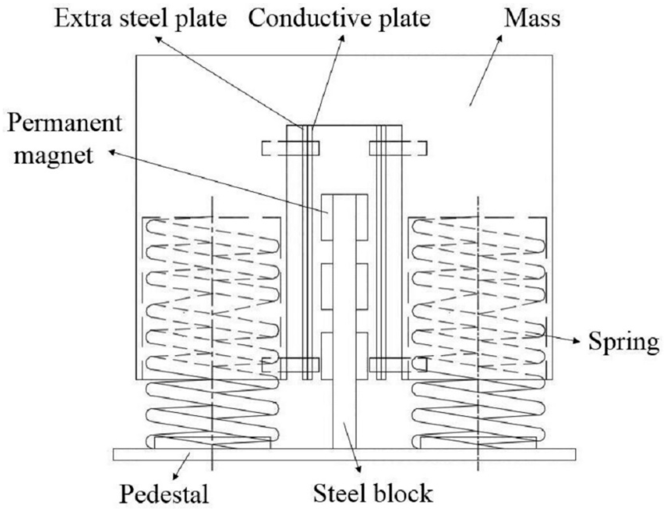
To make it easy for assembly production, convenient for adjusting the eddy current damping and magnetic shielding, a new adaptive-passive ECTMD configuration is proposed, with its schematic diagram shown in Figure 1.
As can be seen from Figure 1, a steel block is fixed with the pedestal, which is used to adsorb permanent magnets. There is a notch pass through the mass, and there are four channels in both sides wall of the groove, which are used to insert screws. Therefore, conductive plates and extra steel plates, which also have four channels in the corresponding position, can set into screws. The eddy current damping can be adjusted easily through adjusting the air gap between conductive plates and magnets.
The eddy current damping is caused by the relative motion between the magnet and the conductive plate. If the charge motion on conductive surface is ignored, the electric current density can be written as [15]:
where is the conductive coefficient of the conductive plate, is the relative velocity between the magnets and conductive plates and is magnetic induction intensity.
The damping force is calculated by the Lorentz equation [13]:
When the conductive plate’s movement direction is perpendicular to the direction of the magnetic induction intensity , the value of the Lorentz force can be written as:
where is the thickness of the conductive plate, and can be simplified as the area which the magnet is projected onto the conductor plate. Finally, a linear damping coefficient can be defined as:
In Equation (4), it is difficult to determine the magnetic induction intensity because it is depended on the magnets’ adsorption position, material and thickness of the conductive plate, and thickness of the extra steel plate. Consequently, the finite element model is built in Opera3D, a finite element analysis software of electromagnetic field.
2.2. Finite Element Model of Adaptive-Passive ECTMD
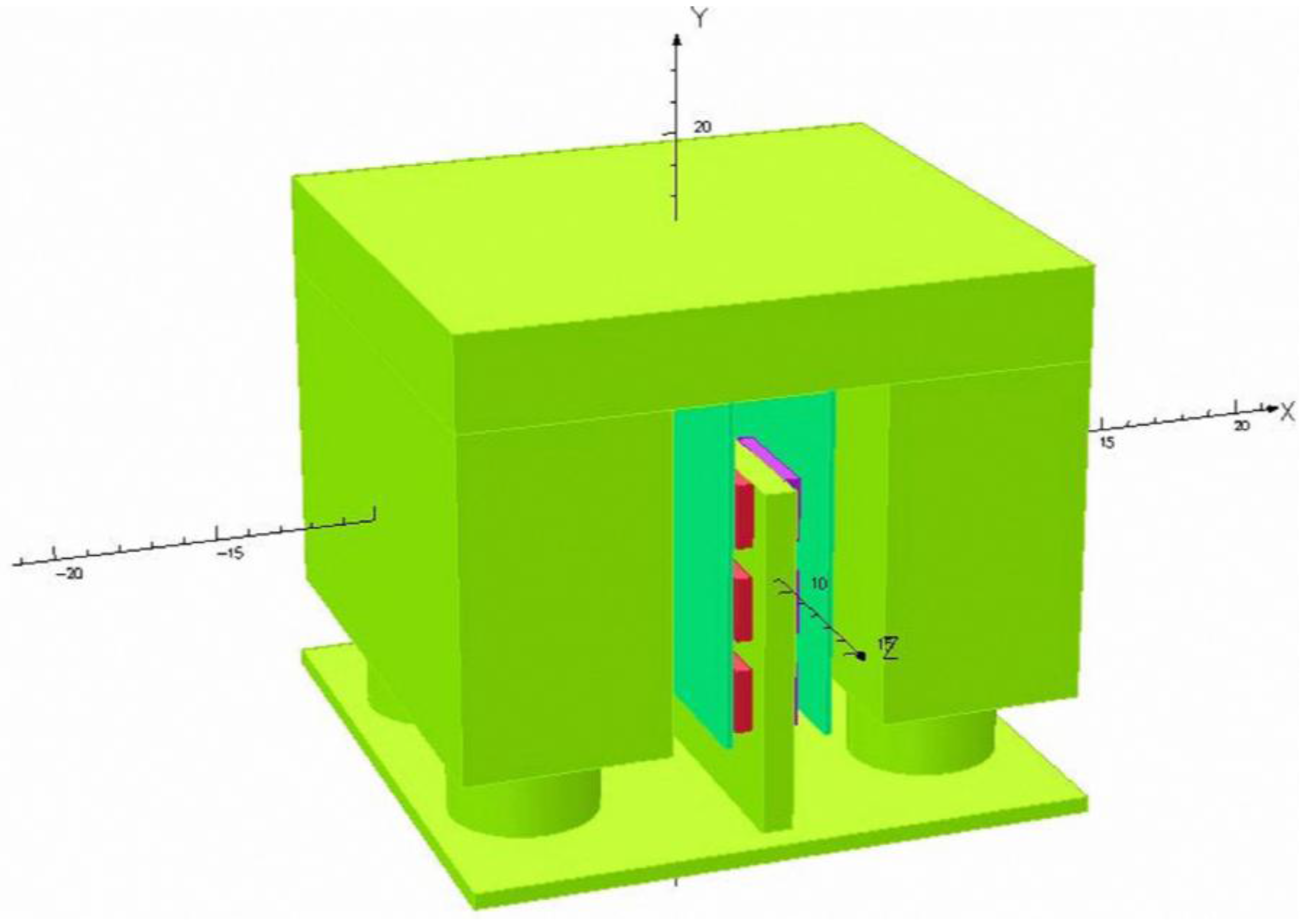
In Opera3D, the mass of adaptive-passive ECTMD is 20 kg, with the size being 200 mm in length, 200 mm in width and 175 mm in height. The frequency of this device is 2.0 Hz. The permeant magnet is composed of N35 (NdFeB) material, with its size being 40 mm in length, 20 mm in width and 5 mm in height. Material of the conductive plate is copper, and it is 180 mm in length and 110 mm in width. The finite element model of the adaptive–passive ECTMD is shown in Figure 2.
The magnetic induction intensity is very important and is mainly depended on the magnets’ adsorption position, thickness of the conductive plate, thickness of the extra steel plate and air gaps. Therefore, these four important parameters will be investigated in detail in Section 3 through a parametric study.
3. Parametric Study
3.1. Effect of the Magnets’ Adsorption Position
Considering the size compatibility of magnets and steel block, nine alternative positions are designed and they are shown in Figure 3.
In this section, 2 mm thickness copper plates are chosen and the air gap is set to be 5 mm. It is obvious that the larger magnetic induction intensity is, the larger linear damping coefficient will be. The eddy current is produced by the whole conductive plate, on which the magnetic induction intensity is not distributed uniformly. Consequently, it is more meaningful to study the surface integral magnetic induction intensity and the average magnetic induction intensity. To compare the effects of adsorption position of permanent magnets on magnetic induction intensity , nine cases are set in Table 1. The corresponding magnetic induction intensity is shown in Table 2.
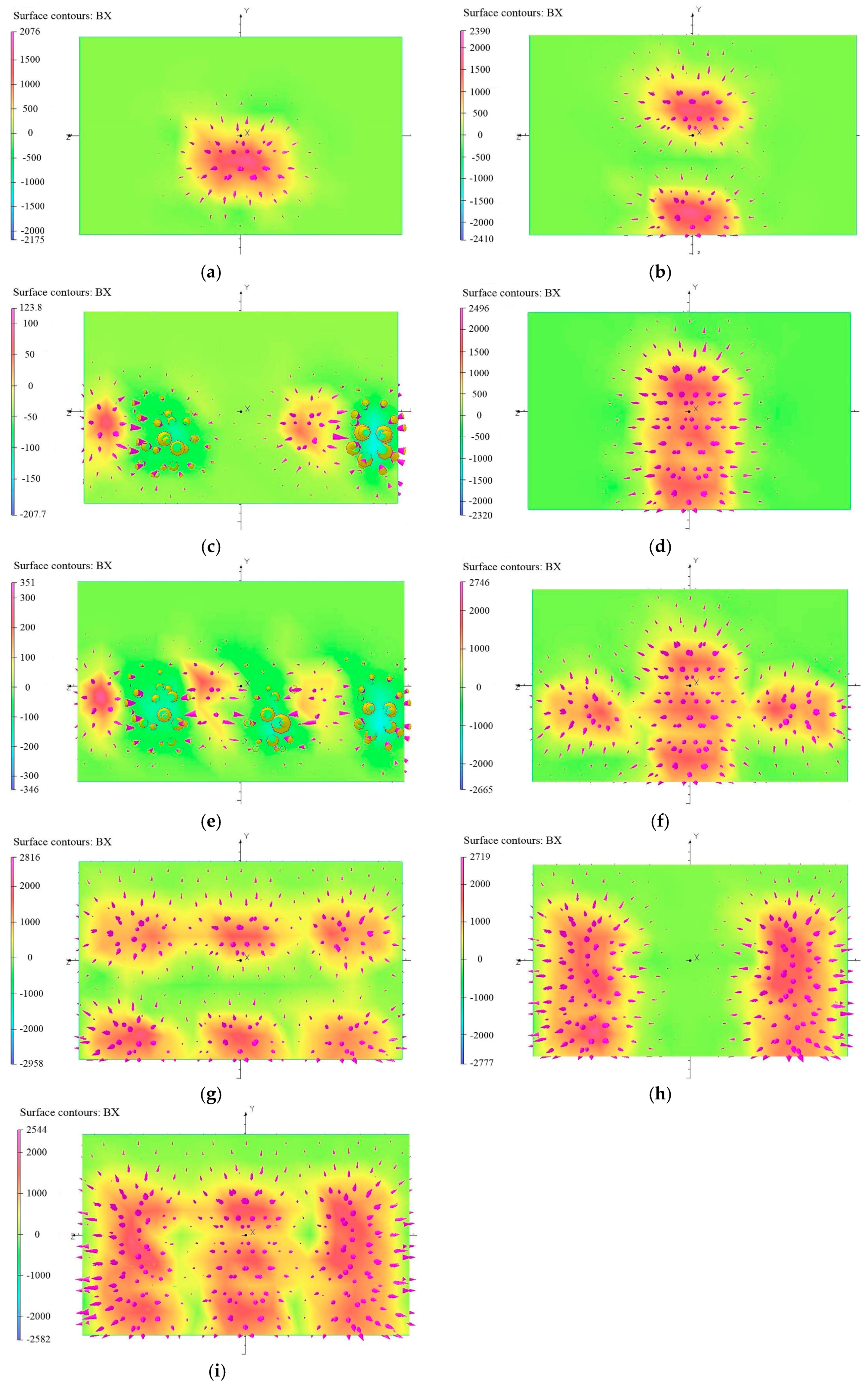
To further study the results in Table 2, the following evaluation indexes are defined [47]. If the sign of local magnetic induction intensity is the same as the average value, then this kind of local magnetic induction intensity is called “beneficial magnetic induction intensity” and this area is called “beneficial area”. Otherwise, they will be called “adverse magnetic induction intensity” and “adverse area”. From the average values in nine cases, it is clear that case 9 is the best; however, the distribution of magnetic induction intensity in the copper plate is also very important, and they are shown in Figure 4.
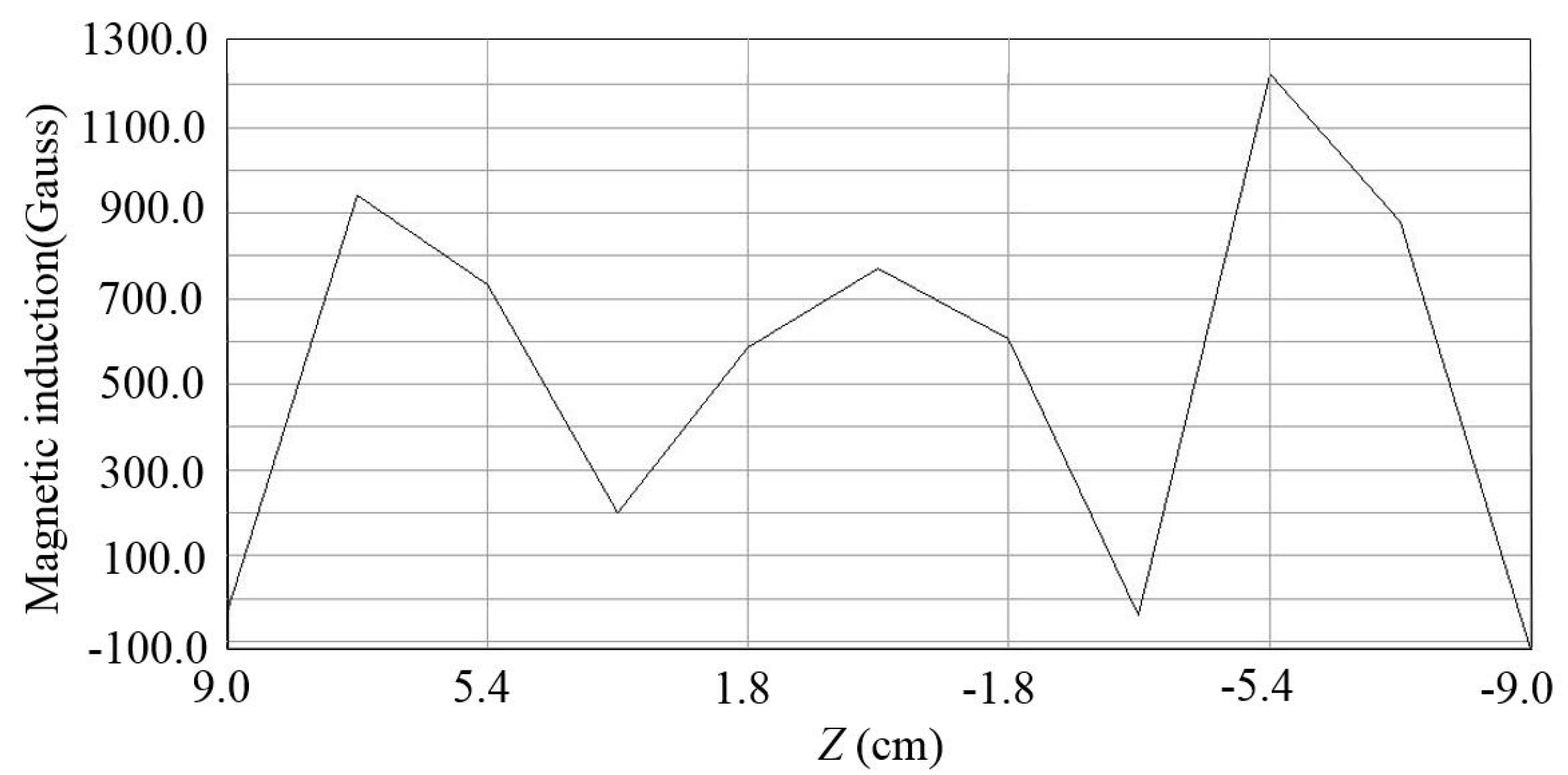
In Table 2, the average values of case 3 and case 5 are negative. As can be seen in Figure 4c,e, the adverse area is almost the same as the beneficial area; therefore, the resultant value is very small, which means that the magnetic induction intensity is small, leading to litter damping effects. The principle of how to choose the adsorption position of permanent magnets is to make the beneficial magnetic induction intensity far larger than the adverse magnetic induction intensity, and the beneficial area far larger than the adverse area. It can also be seen from Figure 4 that the area which the magnet is projected onto the copper plate has larger magnetic induction intensity than its surrounding area, and the magnetic induction intensity decreases sharply in surrounding areas. To illustrate more clearly, take case 9 as an example, the line distribution of magnetic induction intensity in the midline of long side direction is shown in Figure 5. It can be seen that the positions of three crests are the positions which the magnets are projected onto the copper plate, and in the surrounding areas; the magnetic induction intensity decreases sharply.
3.2. Effect of Thickness of Conductive Plates and Extra Steel Plates
In this section, thickness of copper plates and extra steel plates are discussed based on case 9. Thickness of copper plates are 2 mm, 4 mm, 6 mm and 8 mm. The extra steel plate is close to the back of the copper plate and thickness of extra plates are 0 mm (no extra steel plate), 2 mm, 4 mm, 6 mm and 8 mm. The air gap is set to be 5 mm.
Considering the eddy current damping is a linear damping, the mass is given a 20 mm/s vertical velocity. The total Lorentz force and instantaneous eddy power are calculated. The total damping coefficient is calculated from Lorentz force. The vibration energy of adaptive–passive ECTMD is dissipated by the heat of the copper plate; therefore, the damping coefficient calculated from instantaneous eddy power is named the effective damping coefficient . The new evaluation index “damping loss coefficient” is defined as:
The parametric study results of 20 conditions are shown in Table 3.
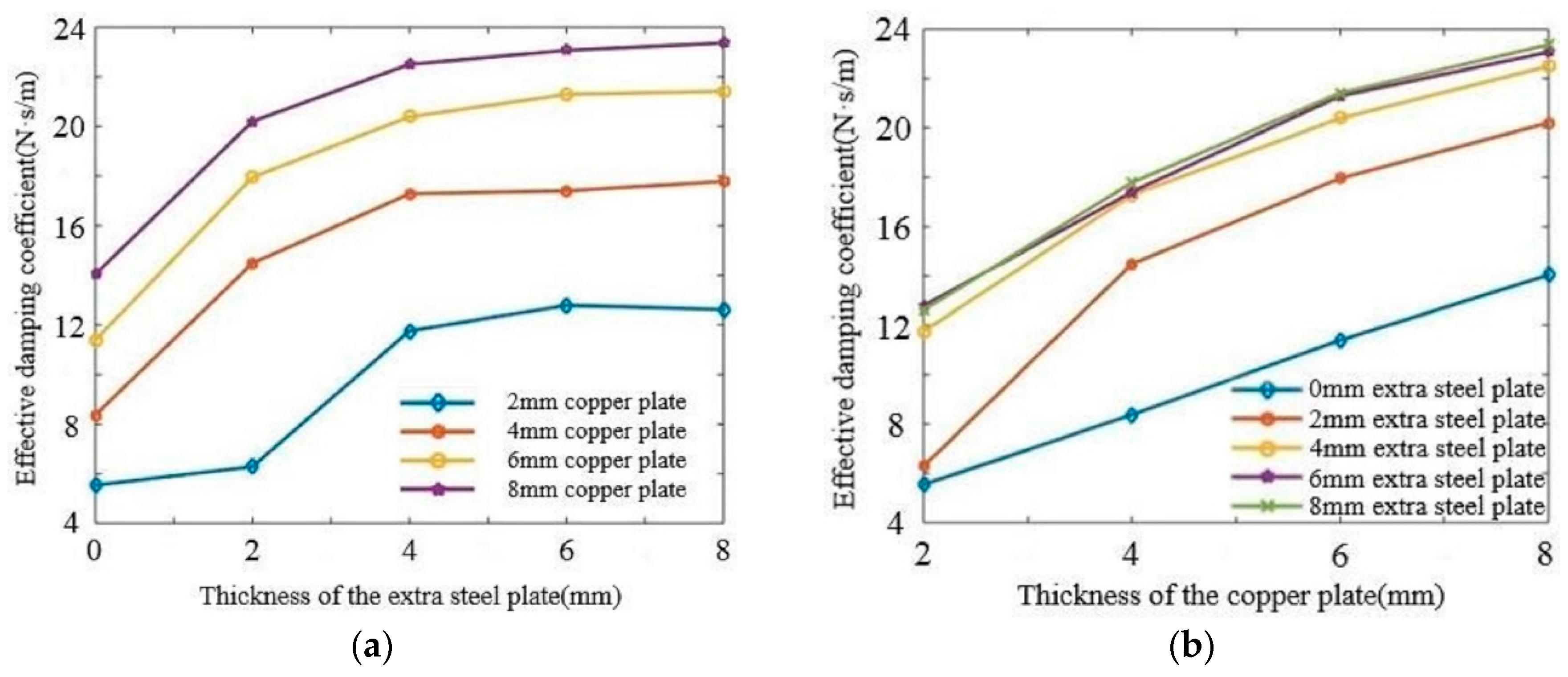
In an ideal condition, the total damping coefficient is equal to the effective damping coefficient . However, because of the mutual interference and offset between eddy current in the copper plate, there is a damping loss ineluctably. To illustrate more clearly, the effective damping coefficient as a function of the thickness of extra steel plates and conductive copper plates is shown in Figure 6.
It can be seen from Figure 6a that with a certain copper plate, effective damping coefficient increases with the increasing of thickness of the extra steel plate, and the result of 6 mm extra steel plate is almost the same as 8 mm extra steel plate. From Figure 6b, it is clear that with a certain extra steel plate, effective damping coefficient increases with the increasing of thickness of the copper plate, and the result of 4 mm extra steel plate, 6 mm extra steel plate and 8 mm extra steel plate are very close. Consequently, from the results of Figure 6, for case 9, combination of 8 mm copper plate and 6 mm extra steel plate, are chosen for the next simulation condition.
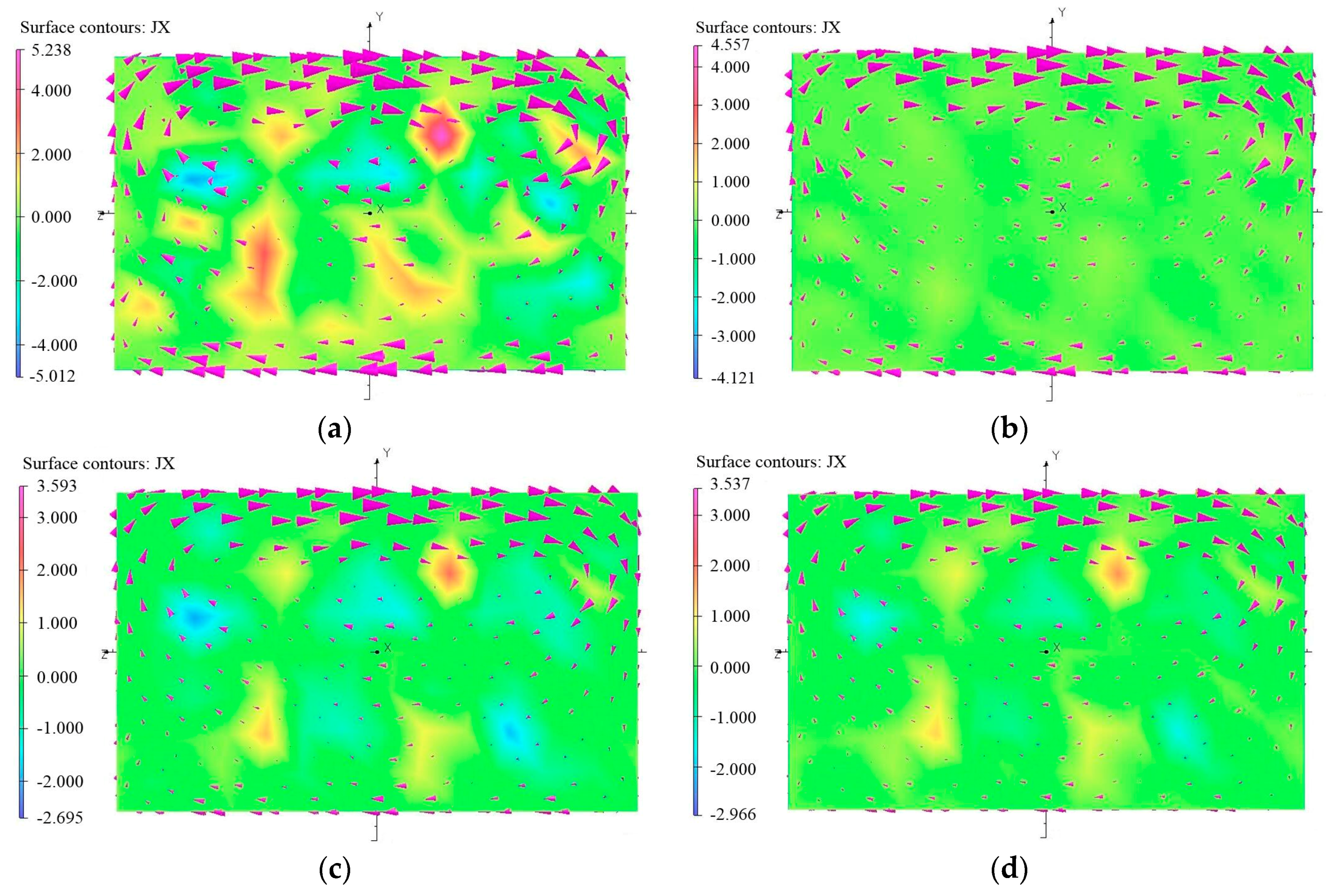
The vibration energy of adaptive–passive ECTMD is dissipated by the heat of the conductive plate, which may be a waste of energy, and it would be better to develop a kind of power recovery unit to recover the eddy current. The variation of temperature in the conductive plate is very small and the heat will dissipate into the air very quickly. Figure 7 shows the distribution of eddy current in the copper plate. It can be seen that there are large eddy currents around the copper plate. In the copper plate, there is some small eddy current and they will join in the large eddy current. The maximum electric current density of these four cases are incremental, while the minimum electric current density and damping loss coefficient are degressive. Consequently, it could be concluded that the more uniform the distribution of electric current density, the smaller the damping loss coefficient will be.
3.3. Effect of the Air Gap
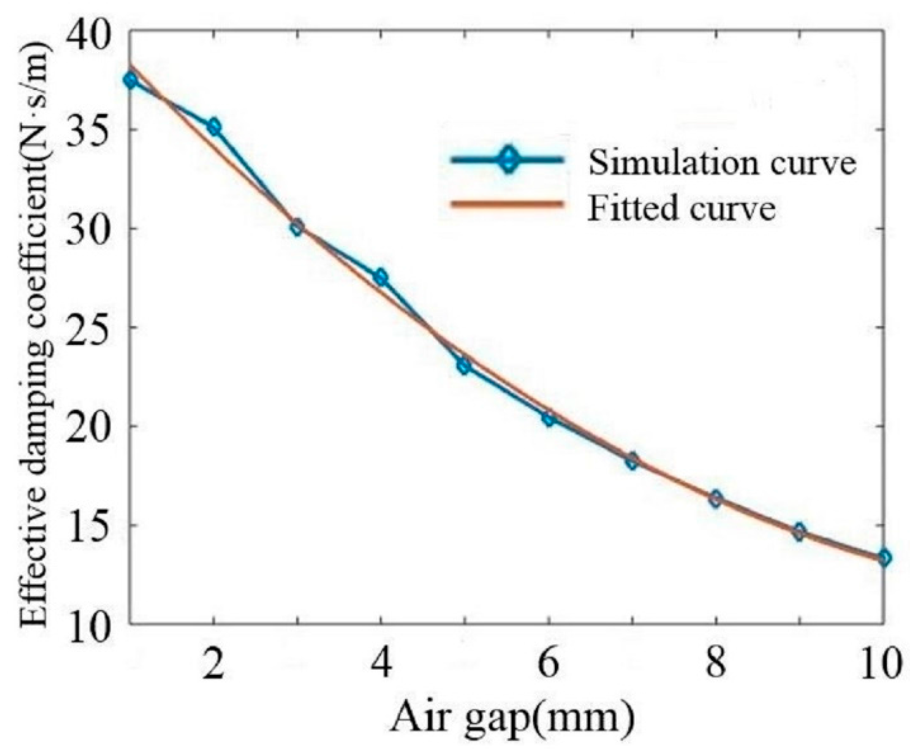
In this section, air gaps are chosen to be from 1 mm to 10 mm with a 1 mm increment. The mass is given a 20 mm/s vertical velocity and the results of effective damping coefficients are shown in Table 4:
The relationship between the effective damping coefficient and air gap is fitted through a quadratic function:
where is the air gap.
The effective damping coefficient as a function of air gap and the fitting curve are shown in Figure 8. As can be seen from Figure 8, they are fitted well. With this fitting function, the damping ratio of the proposed device can be adjusted passively easily through adjusting the air gap.
The maximum and minimum damping coefficient are obtained from Table 4, and the maximum damping coefficient is 37.500 N·s/m while the minimum is 13.325 N·s/m. The mass and frequency of the ECTMD are 2000 kg and 2.0 Hz, respectively, which have been introduced in Section 2.2. The damping ratio is calculated by:
Therefore, the damping ratio adjustment range of this ECTMD is from 2.65% to 7.46%, in which the 7.46% damping ratio corresponds to the air gap being 1 mm, and the 2.65% damping ratio corresponds to the air gap being 10 mm.
4. Design Method of Adaptive-Passive ECTMD
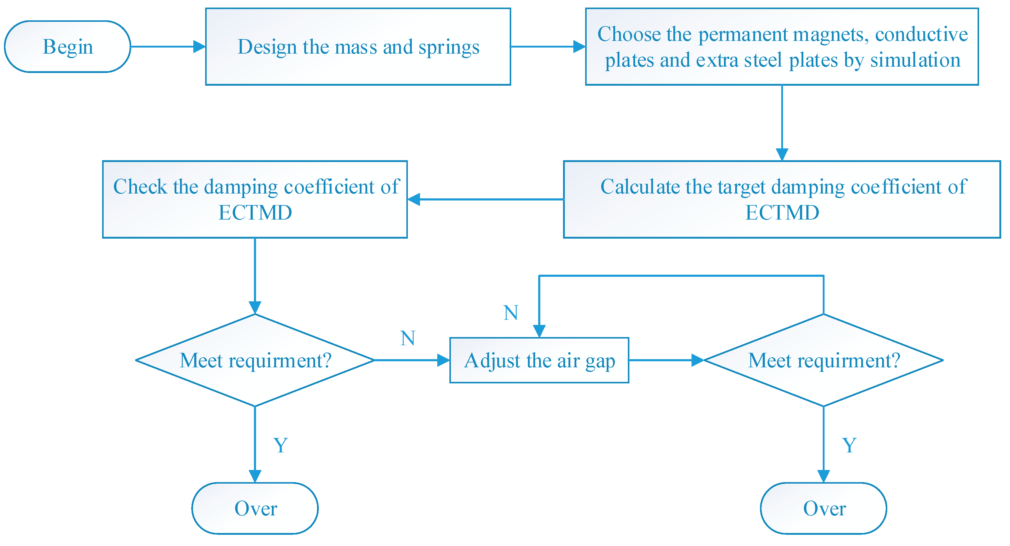
The design method flow chart of adaptive-passive ECTMD is shown in Figure 9. Firstly, a medium size ECTMD, e.g., 1000 kg mass and 2.0 Hz frequency is preliminary designed. Then, certain important parameters should be determined based on the parametric study introduced in Section 3, that is, the position of magnets, thickness of conductive plate and thickness of extra steel plate are set. At the same time, a fitting function (just as Equation (8)) has been obtained and the ECTMD has a damping ratio adjustment range. If the needed size of ECTMD is different from the preliminary one, the height of mass and springs can be changed to meet the requirement, and the damping ratio can be changed through adjusting the air gap easily. The damping ratio adjustment range can be expanded through expanding the notch which passes through the mass. Consequently, this design method of adaptive–passive ECTMD is easy to be implemented and has a great potential in engineering applications.
5. Semi-Active ECTMD with Variable Damping Element
5.1. Control Algorithm
Based on the aforementioned discussion, the previous adaptive–passive ECTMD is now upgraded to a semi-active one in this section, which is capable of adjusting its eddy current damping through adjusting its air gap in real-time.
As for the semi-active ECTMD, there will be two acceleration sensors, one is put at the mass of ECTMD, and the other is put at the middle span of the footbridge. There will be an actuator behind the extra steel plate on both sides, which is controlled by a microcontroller. The microcontroller receives acceleration sensors’ signal and controls actuator in real-time. Therefore, the actuator can adjust the air gap between conductive plates and magnets in real-time through pushing and pulling the extra steel plate. In this way, the eddy current damper is adjusted in real-time. Schematic diagram of the semi-active ECTMD is shown in Figure 10.
The dynamic equation of a linear system under the control force and an external excitation can be written as:
where is the mass matrix. is the damping matrix. is the stiffness matrix. is the external force. is the control force. is the position vector of control force. is the displacement vector and the over-dot indicates the derivative with respect to time.
Then the state equation can be written as:
where the state vector . , , . The control force is calculated according to the linear-quadratic-Gaussian (LQG) control algorithm.
The LQG control algorithm has been widely used for active control design of civil structures [48,49]. One of the advantages of LQG control is that the external excitation will drop out of the state feedback control design [50,51]. The external force is assumed to be a zero-mean white noise process with Gaussian distribution and constant covariance [52]. According to the LQG algorithm, the control force is determined by minimizing the following quadratic expression of the cost function [53]:
where is the cost function. is a positive semi-definite weighting matrix. is a positive weighting matrix. is the total time of calculation.
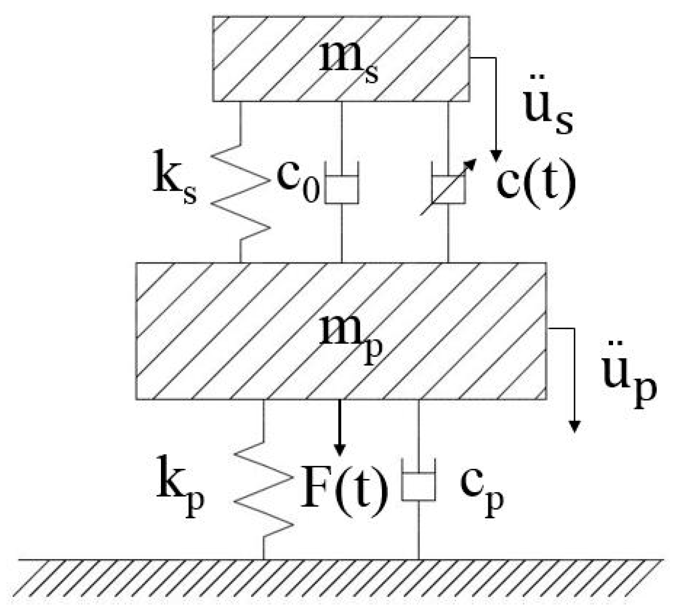
Because the footbridge’s first vertical mode is dominant and can be simplified as a single-degree-of-freedom (SDOF) structure, the dynamic system is consisted of a SDOF primary structure and the semi-active ECTMD, which is shown in Figure 11.
The motion equations of the dynamic system under an external excitation can be written as:
where and are the mass of the primary system and semi-active ECTMD respectively. and are the viscous damping coefficient of the primary system and constant viscous damping coefficient of semi-active ECTMD respectively. and represent the stiffness coefficient of the primary system and semi-active ECTMD respectively. and mean the absolute displacement of the primary system and semi-active ECTMD respectively. means the variable viscous damping coefficient of semi-active ECTMD.
In this system, the control force is provided by . Therefore, can be calculated as:
where , .
Considering that the needed control force calculated from LQG algorithm may exceed the range that the semi-active ECTMD can afford, the following boundary is set:
where is the maximum of the variable damping coefficient, and is the minimum of the variable damping coefficient.
5.2. Case Study
Vertical TMDs are widely used in controlling human-induced vibrations of footbridges and floors [54,55,56,57,58,59]. In this section, the proposed upgraded semi-active ECTMD with 20 kg mass, 2.0 Hz frequency and an adjustable damping coefficient ranging from 13.325 N·s/m to 37.500 N·s/m (which are obtained from Table 4), which means that its constant damping coefficient is 13.325 N·s/m and the variable damping coefficient is from 0 to 24.175 N·s/m, and is simulated to control a footbridge model with 2000 kg mass, 2.0 Hz frequency and 2.00% damping ratio.
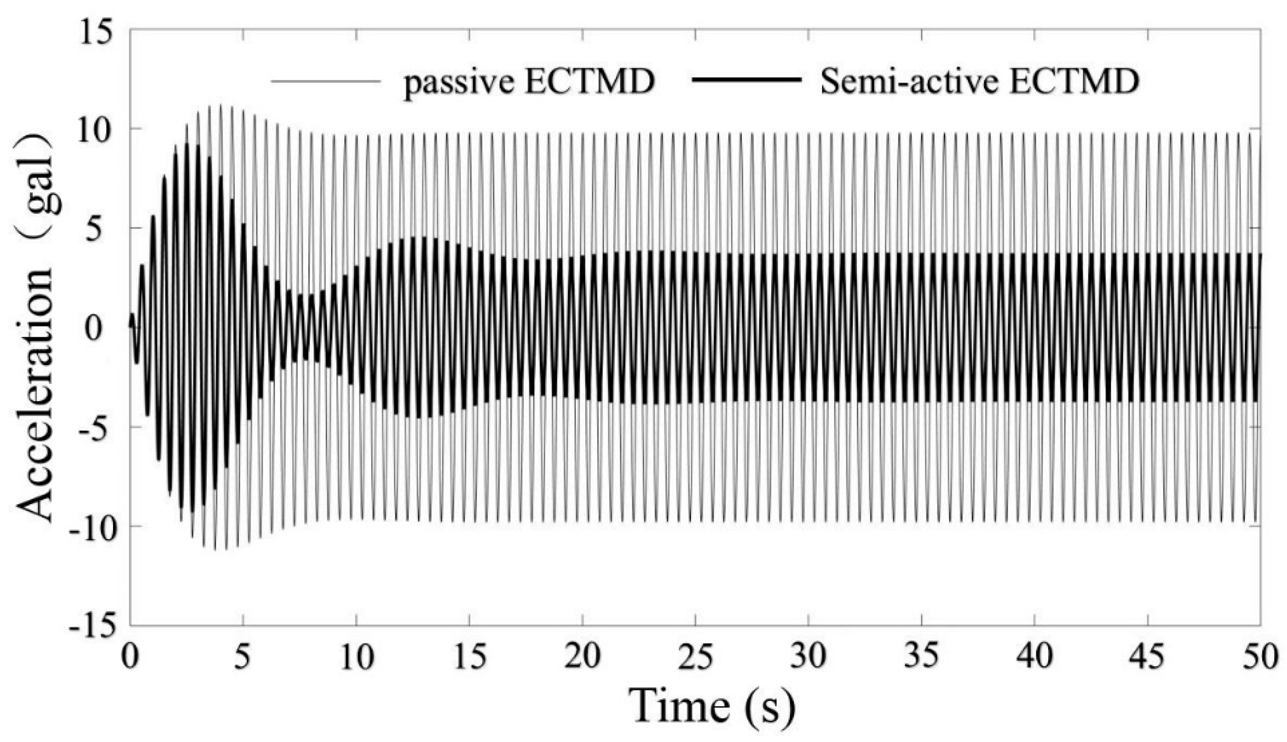
First of all, the footbridge model is excited by three harmonic excitations with 1.8 Hz, 2.0 Hz and 2.2 Hz frequencies. The comparison of structural response under 2.0 Hz harmonic excitation is shown in Figure 12. The passive ECTMD is an optimal one, with 20 kg mass, 2.0 Hz frequency and 6.09% damping ratio (corresponding to 30.611 N·s/m damping coefficient). Note that the unit of acceleration “gal” means “1 cm/s2”.
As can be seen from Figure 12, in steady state, compared to passive ECTMD, the semi-active ECTMD can decrease the structural peak acceleration to a great extent.
In order to verify the effect of semi-active ECTMD further, human-induced vibrations of 1.8 Hz, 2.0 Hz and 2.2 Hz are simulated. According to [60,61], a vertical force is often modelled as a sum of a static and a dynamic component as Equation (16).
where is the fundamental walking or running frequency, is the body weight, and are the amplitude and the phase angle of the ith harmonic excitation, respectively. Table 5, adapted from [62], shows the first three dynamic load factors, and for walking, running, and jumping, respectively, in Equation (16).
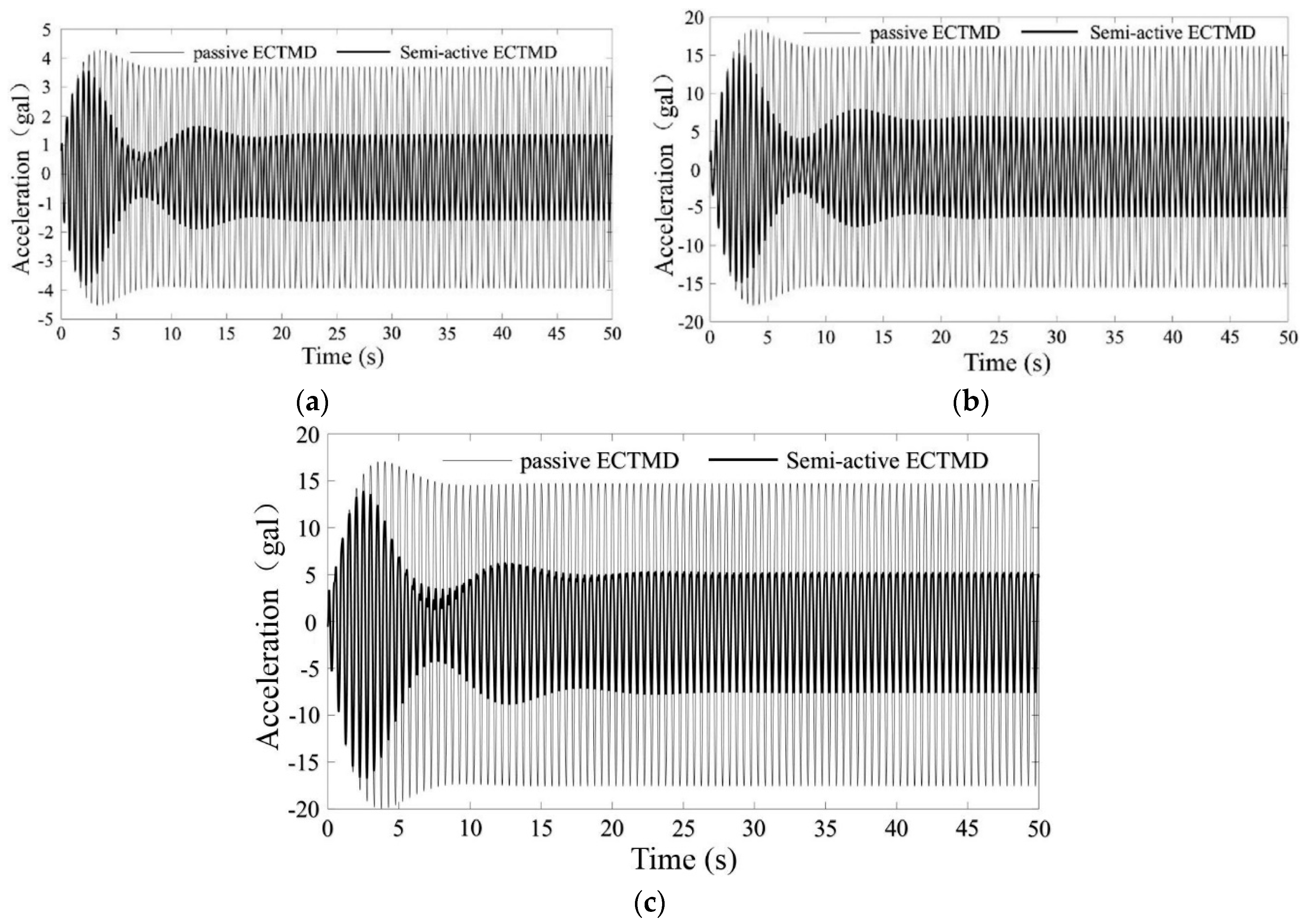
The comparisons of structural response under 2.0 Hz walking, running and jumping excitations are shown in Figure 13. The detailed results of the harmonic and human-induced excitation simulations are shown in Table 6.
From Figure 13 and Table 6, it is clear that under the three 2.0 Hz resonance harmonic and human-induced excitations, the structural peak accelerations are the largest and the reductions of semi-active ECTMD are also the largest comparing to the passive ECTMD scenario. Under the other two frequencies of harmonic and human-induced excitations, the semi-active ECTMD also has better effects on controlling peak accelerations.
Furthermore, an extended harmonic excitation frequency ranging from 1 Hz to 3 Hz is discussed in Table 7.
As can be seen from Table 7, when the harmonic excitation frequency deviates from the resonance range around 2.0 Hz, the amplitude of footbridge model is small and the semi-active ECTMD also behaves better than the passive one.
Consequently, by incorporating certain control algorithm into the proposed adaptive–passive ECTMD, in which the adjusting mechanism for air gap is very easy to be implemented, the vibration control effects can be further increased. In real projects, both the passive ECTMD and the upgraded semi-active one can be applied based on the client’s requirements.
6. Conclusions
The traditional tuned mass damper (TMD) with viscous damper has many unsustainable problems such as poor durability, sensitive to the change of temperature, difficulty to adjust the damping, oil leakage, etc. Eddy current damper is green and sustainable, which is induced by the relative motion between the permanent magnet and the conductive plate, and the vibration energy is dissipated by the heat of the conductive plate. In this paper, a new adaptive–passive eddy current tuned mass damper (ECTMD) is proposed and studied through Opera3D. Then, the corresponding design method with an easy implementation is presented and at last, the previous adaptive–passive ECTMD is upgraded to a semi-active one, which can adjust its eddy current damping through adjusting its air gap in real-time, based on the LQG algorithm. The effectiveness of semi-active ECTMD is studied through harmonic excitations and human-induced excitations. The following conclusions can be drawn:
- The proposed adaptive–passive ECTMD has the advantages of being friendly to the environment, suitable for assembly production, economical, free of additional stiffness, etc. The most important advantage is that the damping ratio can be adjusted very easily through adjusting the air gap between conductive plates and magnets. Therefore, it meets the sustainability requirement.
- Four important parameters, e.g., adsorption position of permanent magnets, thickness of the conductive plate, thickness of the extra steel plate and the air gap between permanent magnets and the conductive plate, influence the damping effects. However, the absorption position of permeant magnets has a relatively larger influence on the magnetic induction intensity.
- The proposed two new evaluation indexes (beneficial magnetic induction intensity and adverse magnetic induction intensity) are useful indications of the damping mechanism of the device. The effective damping coefficient as a function of the air gap and the fitting function can easily be obtained. With this fitting function, the damping ratio of the proposed ECTMD can be adjusted both passively and semi-actively easily through adjusting the air gap.
- The passive ECTMD can be conveniently upgraded to a semi-active one because the adjusting mechanism for air gap is very easy to be implemented. By using the LQG control algorithm, this semi-active ECTMD has much better control effects over the optimized passive one under harmonic and human-induced excitations. Both devices can be used in engineering projects based on the client’s demands.
Acknowledgments
This project was supported as a project of the National Natural Science Foundation of China (Grant No. 51478361).
Author Contributions
Weixing Shi proposed the idea, Liangkun Wang carried out the numerical simulations and wrote the paper. Zheng Lu conceived the analytical method, provided valuable discussions and revised the paper. Hui Gao carried out the parametric study.
Conflicts of Interest
The authors declare no conflict of interest.
References
- Lu, Z.; Chen, X.; Zhang, D.; Dai, K. Experimental and analytical study on the performance of particle tuned mass dampers under seismic excitation. Earthq. Eng. Struct. Dyn. 2017, 46, 697–714. [Google Scholar] [CrossRef]
- Lu, Z.; Wang, D.; Masri, S.F.; Lu, X. An experimental study of vibration control of wind-excited high-rise buildings using particle tuned mass dampers. Smart Struct. Syst. 2016, 18, 93–115. [Google Scholar] [CrossRef]
- Dai, K.; Wang, J.; Mao, R.; Lu, Z.; Chen, S. Experimental investigation on dynamic characterization and seismic control performance of a TLPD system. Struct. Des. Tall Spec. Build. 2017, 26, e1350. [Google Scholar] [CrossRef]
- Lu, Z.; Wang, Z.; Masri, S.F.; Lu, X. Particle impact dampers: Past, Present, and Future. Struct. Control Health Monit. 2018, 25, e2508. [Google Scholar] [CrossRef]
- Lu, Z.; Chen, X.; Zhou, Y. An equivalent method for optimization of particle tuned mass damper based on experimental parametric study. J. Sound Vib. 2017. [Google Scholar] [CrossRef]
- Lu, Z.; Huang, B.; Zhou, Y. Theoretical study and experimental validation on the energy dissipation mechanism of particle dampers. Struct. Control Health Monit. 2017. [Google Scholar] [CrossRef]
- Brownjohn, J.; Fok, P.; Roche, M.; Moyo, P. Long span steel pedestrian bridge at Singapore Changi Airport—Part 1: Prediction of vibration serviceability problems. Eng. Strict. 2004, 82, 21–27. [Google Scholar]
- Li, Q.; Fan, J.; Nie, J.; Li, Q.; Chen, Y. Crowd-induced random vibration of footbridge and vibration control using multiple tuned mass dampers. J. Sound Vib. 2010, 329, 4068–4092. [Google Scholar] [CrossRef]
- Domaneschi, M.; Martinelli, L. Refined optimal passive control of buffeting-induced wind loading of a suspension bridge. Wind Struct. Int. J. 2014, 18, 1–20. [Google Scholar] [CrossRef]
- Domaneschi, M.; Martinelli, L.; Po, E. Control of Wind Buffeting Vibrations in a Suspension Bridge by TMD: Hybridization and robustness issues. Comput. Struct. 2015, 155, 3–17. [Google Scholar] [CrossRef]
- Domaneschi, M.; Martinelli, L. Earthquake resilience-based control solutions for the extended benchmark cable-stayed bridge. J. Struct. Eng. 2016, 142, C4015009. [Google Scholar] [CrossRef]
- Domaneschi, M.; Perotti, F.; Martinelli, L. Wind and earthquake protection of cable-supported bridges. Bridg. Eng. 2016, 9307, 1–15. [Google Scholar] [CrossRef]
- Casciati, F.; Giuliano, F. Performance of multi-TMD in the towers of suspension bridges. J. Vib. Control 2009, 15, 821–847. [Google Scholar] [CrossRef]
- Wang, Z.; Chen, Z.; Wang, J. Feasibility study of a large-scale tuned mass damper with eddy current damping mechanism. Earthq. Eng. Eng. Vib. 2012, 11, 391–401. [Google Scholar] [CrossRef]
- Hu, Y.; Liu, L.; Rahimi, S. Seismic vibration control of 3D steel frames with irregular plans using eccentrically placed MR dampers. Sustainability 2017, 9, 1255. [Google Scholar] [CrossRef]
- Pluk, K.; Beek, T.; Jansen, J.; Lomonova, E. Modeling and measurements on a finite rectangular conducting plate in an eddy current damper. IEEE Trans. Ind. Electron. 2014, 61, 4061–4072. [Google Scholar] [CrossRef]
- Ebrahimi, B.; Khamesee, M.; Golnaraghi, M. Design and modeling of a magnetic shock absorber based on eddy current damping effect. J. Sound Vib. 2008, 315, 875–889. [Google Scholar] [CrossRef]
- Lu, X.; Zhang, Q.; Weng, D.; Zhou, Z.; Wang, S.; Mahin, S.; Ding, S.; Qian, F. Improving performance of a super tall building using a new eddy current tuned mass damper. Struct. Control Health Monit. 2017, 24, e1882. [Google Scholar] [CrossRef]
- Bourquin, F.; Caruso, G.; Peigney, M.; Siegert, D. Magnetically tuned mass dampers for optimal vibration damping of large structures. Smart Mater. Struct. 2014, 23, 85009. [Google Scholar] [CrossRef]
- Bae, J.; Kwak, M.; Inman, D. Vibration suppression of a cantilever beam using eddy current damper. J. Sound Vib. 2005, 284, 805–824. [Google Scholar] [CrossRef]
- Sodano, H.; Inman, D. Non-contact vibration control system employing an active eddy current damper. J. Sound Vib. 2007, 305, 596–613. [Google Scholar] [CrossRef]
- Sodano, H.; Inman, D. Modeling of a new active eddy current vibration control system. J. Dyn. Syst. Meas. Control 2008, 130, 21009. [Google Scholar] [CrossRef]
- Sodano, H.; Bae, J.; Inman, D.; Belvin, W. Concept and model of eddy current damper for vibration suppression of a beam. J. Sound Vib. 2005, 288, 1177–1196. [Google Scholar] [CrossRef]
- Amjadian, M.; Agrawal, A. A passive electromagnetic eddy current friction damper (PEMECFD): Theoretical and analytical modeling. Struct. Control Health Monit. 2017, 24, e1978. [Google Scholar] [CrossRef]
- Maddah, A.; Hojjat, Y.; Karafi, M.; Ashory, M. Reduction of magneto rheological dampers stiffness by incorporating of an eddy current damper. J. Sound Vib. 2017, 396, 51–68. [Google Scholar] [CrossRef]
- Chen, J.; Lu, G.; Li, Y.; Wang, T.; Wang, W.; Song, G. Experimental study on robustness of an eddy current-tuned mass damper. Appl. Sci. 2017, 7, 895. [Google Scholar] [CrossRef]
- Wang, W.; Dalton, D.; Hua, X.; Wang, X.; Chen, Z.; Song, G. Experimental study on vibration control of a submerged pipeline model by eddy current tuned mass damper. Appl. Sci. 2017, 7, 987. [Google Scholar] [CrossRef]
- Eason, R.P.; Sun, C.; Dick, A.J.; Nagarajaiah, S. Attenuation of a linear oscillator using a nonlinear and a semi-active tuned mass damper in series. J. Sound Vib. 2013, 332, 154–166. [Google Scholar] [CrossRef]
- Sun, C.; Nagarajaiah, S.; Dick, A.J. Family of smart tuned mass damper with variable frequency under harmonic excitation and ground motions: Closed-form evaluation. Smart Struct. Syst. 2014, 13, 319–341. [Google Scholar] [CrossRef]
- Li, C.; Cao, B. Hybrid active tuned mass dampers for structures under the ground acceleration. Struct. Control Health Monit. 2015, 22, 757–773. [Google Scholar] [CrossRef]
- Lin, G.; Lin, C.; Lu, L.Y.; Ho, Y. Experimental verification of seismic vibration control using semi-active friction tuned mass damper. Earthq. Eng. Struct. Dyn. 2012, 41, 813–830. [Google Scholar] [CrossRef]
- Nagarajaiah, S. Adaptive passive, semi-active, smart tuned mass dampers: Identification and control using empirical mode decomposition, Hilbert transform, and short-term Fourier transform. Struct. Control Health Monit. 2009, 16, 800–841. [Google Scholar] [CrossRef]
- Nagarajaiah, S.; Varadarajan, N. Short time Fourier transform algorithm for wind response control of buildings with variable stiffness TMD. Eng. Struct. 2005, 27, 431–441. [Google Scholar] [CrossRef]
- Lin, P.Y.; Chung, L.L. Semi-active control of building structures with semi-active tuned mass damper. Comput. Aided Civ. Infrastruct. Eng. 2005, 20, 35–51. [Google Scholar] [CrossRef]
- Sun, C.; Nagarajaiah, S. Study on semi-active tuned mass damper with variable damping and stiffness under seismic excitations. Struct. Control Health Monit. 2014, 21, 890–906. [Google Scholar] [CrossRef]
- Lin, G.; Lin, C.; Chen, B.; Soong, T. Vibration control performance of tuned mass dampers with resettable variable stiffness. Eng. Struct. 2015, 83, 187–197. [Google Scholar] [CrossRef]
- Emiliano, M.; Alessandro, D. Robust design of mass-uncertain rolling-pendulum TMDs for the seismic protection of buildings. Mech. Syst. Signal Process. 2009, 23, 127–147. [Google Scholar]
- Chang, M.; Lin, C.; Ueng, J.; Hsieh, K.; Wang, J. Experimental study on adjustable tuned mass damper to reduce floor vibrations due to machinery. Struct. Control Health Monit. 2013, 21, 890–906. [Google Scholar] [CrossRef]
- Berardengo, M.; Cigada, A.; Guanziroli, F.; Manzoni, S. Modelling and control of an adaptive tuned mass damper based on shape memory alloys and eddy currents. J. Sound Vib. 2015, 349, 18–38. [Google Scholar] [CrossRef]
- Rizos, D.; Feltrin, G.; Motavalli, M. Structural identification of a prototype pre-stressable leaf-spring based adaptive tuned mass damper: Nonlinear characterization and classification. Mech. Syst. Signal Process. 2011, 25, 205–221. [Google Scholar] [CrossRef]
- Pietrosanti, D.; Angelis, M.; Basili, M. Optimal design and performance evaluation of systems with tuned mass damper inerter (TMDI). Earthq. Eng. Struct. Dyn. 2017, 46, 1367–1388. [Google Scholar] [CrossRef]
- Brzeski, P.; Perlikowski, P. Effects of play and inerter nonlinearities on the performance of tuned mass damper. Nonlinear Dyn. 2017, 88, 1027–1041. [Google Scholar] [CrossRef]
- Marian, L.; Giaralis, A. Optimal design of a novel tuned mass-damper-inerter (TMDI) passive vibration control configuration for stochastically support-excited structural systems. Probab. Eng. Mech. 2014, 38, 156–164. [Google Scholar] [CrossRef]
- Giaralis, A.; Petrini, F. Wind-induced vibration mitigation in tall buildings using the tuned mass-damper-inerter. J. Struct. Eng. 2017, 143, 4017127. [Google Scholar] [CrossRef]
- Lazar, I.; Neild, S.; Wagg, D. Vibration suppression of cables using tuned inerter dampers. Eng. Struct. 2016, 122, 62–71. [Google Scholar] [CrossRef]
- OPERA-3D User Guide; QUENCH Code; Cobham Technical Services, Vector Fields Limited: Kidlington, UK, 2013.
- Lu, Z.; Masri, S.; Lu, X. Studies of the performance of particle dampers attached to a two-degree-of-freedom system under random excitation. J. Vib. Control 2011, 17, 1454–1471. [Google Scholar]
- Ni, Y.; Chen, Y.; Ko, J.; Cao, D. Neuro-control of cable vibration using semi-active magneto-rheological dampers. Eng. Struct. 2002, 24, 295–307. [Google Scholar] [CrossRef]
- Zhu, W.; Luo, M.; Dong, L. Semi-active control of wind excited building structures using MR/ER dampers. Probab. Eng. Mech. 2004, 19, 279–285. [Google Scholar] [CrossRef]
- Montazeri, A.; Poshtan, J.; Choobdar, A. Performance and robust stability trade-off in minimax LQG control of vibrations in flexible structures. Eng. Struct. 2009, 31, 2407–2413. [Google Scholar] [CrossRef]
- Dong, X.; Yu, M.; Liao, C.; Chen, W. Comparative research on semi-active control strategies for magneto-rheological suspension. Nonlinear Dyn. 2010, 59, 433–453. [Google Scholar] [CrossRef]
- Gu, Z.; Oyadiji, O. Application of MR damper in structural control using ANFIS method. Comput. Struct. 2008, 86, 427–436. [Google Scholar] [CrossRef]
- Ozbulut, O.; Bitaraf, M.; Hurlebaus, S. Adaptive control of base-isolated structures against near-field earthquakes using variable friction dampers. Eng. Struct. 2011, 33, 3143–3154. [Google Scholar] [CrossRef]
- Lu, Z.; Wang, D.; Zhou, Y. Experimental parametric study on wind-induced vibration control of particle tuned mass damper on a benchmark high-rise building. Struct. Des. Tall Spec. Build. 2017, 26, e1359. [Google Scholar] [CrossRef]
- Casciati, F.; Casciati, S.; Faravelli, L. A contribution to the modelling of human induced excitation on pedestrian bridges. Struct. Saf. 2017, 66, 51–61. [Google Scholar] [CrossRef]
- Zivanovic, S.; Pavic, A.; Reynolds, P. Vibration serviceability of footbridges under human-induced excitation: A literature review. J. Sound Vib. 2005, 279, 1–74. [Google Scholar] [CrossRef] [Green Version]
- Díaz, I.; Reynolds, P. Acceleration feedback control of human-induced floor vibrations. Eng. Struct. 2010, 32, 163–173. [Google Scholar] [CrossRef]
- Lu, X.; Ding, K.; Shi, W.; Weng, D. Tuned mass dampers for human-induced vibration control of the Expo Culture Centre at the World Expo 2010 in Shanghai, China. Struct. Eng. Mech. 2012, 43, 607–621. [Google Scholar] [CrossRef]
- Lu, Z.; Chen, X.; Li, X.; Li, P. Optimization and application of multiple tuned mass dampers in the vibration control of pedestrian bridges. Struct. Eng. Mech. 2017, 62, 55–64. [Google Scholar] [CrossRef]
- Occhiuzzi, A.; Spizzuoco, M.; Ricciardelli, F. Loading models and response control of footbridges excited by running pedestrians. Struct. Control Health Monit. 2010, 15, 349–368. [Google Scholar] [CrossRef]
- Racic, V.; Brownjohn, J.M.W.; Pavic, A. Reproduction and application of human bouncing and jumping forces from visual marker data. J. Sound Vib. 2010, 239, 3397–3416. [Google Scholar] [CrossRef]
- Shi, W.; Wang, L.; Lu, Z. Study on self-adjustable tuned mass damper with variable mass. Struct. Control Health Monit. 2017. [Google Scholar] [CrossRef]
Figure 1.
Schematic diagram of the adaptive-passive ECTMD.

Figure 2.
The finite element model of the adaptive–passive ECTMD.

Figure 3.
Adsorption position of permanent magnets (mm).
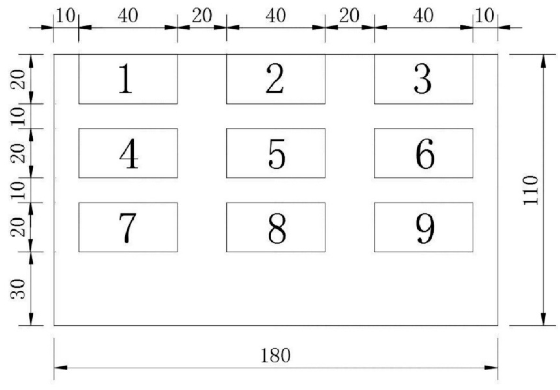
Figure 4.
The distribution cloud pictures of magnetic induction intensity (Gauss). (a) Case 1; (b) Case 2; (c) Case 3; (d) Case 4; (e) Case 5; (f) Case 6; (g) Case 7; (h) Case 8; (i) Case 9.
Figure 4.
The distribution cloud pictures of magnetic induction intensity (Gauss). (a) Case 1; (b) Case 2; (c) Case 3; (d) Case 4; (e) Case 5; (f) Case 6; (g) Case 7; (h) Case 8; (i) Case 9.

Figure 5.
The line distribution of magnetic induction intensity.

Figure 6.
Effective damping coefficient as functions of the thickness of extra steel plates/copper plates using different copper plates/extra steel plates. (a) Using different copper plates; (b) Using different extra steel plates.
Figure 6.
Effective damping coefficient as functions of the thickness of extra steel plates/copper plates using different copper plates/extra steel plates. (a) Using different copper plates; (b) Using different extra steel plates.

Figure 7.
The distribution cloud pictures of electric current density (A/cm2). (a) Case 4; (b) Case 9; (c) Case 14; (d) Case 19.
Figure 7.
The distribution cloud pictures of electric current density (A/cm2). (a) Case 4; (b) Case 9; (c) Case 14; (d) Case 19.

Figure 8.
Effective damping coefficient as a function of air gap and the fitting curve.

Figure 9.
The design method flow chart of adaptive-passive ECTMD.

Figure 10.
Schematic diagram of the semi-active ECTMD.
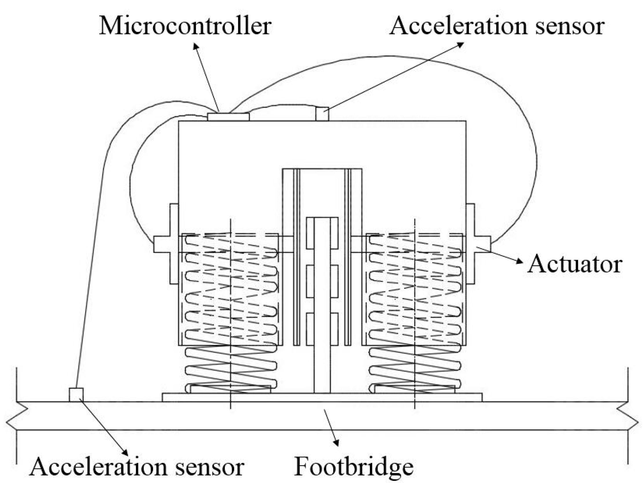
Figure 11.
The dynamic system coupled with semi-active ECTMD under an external excitation.

Figure 12.
The comparison of structural response under 2.0 Hz harmonic excitation.

Figure 13.
The comparisons of structural responses under 2.0Hz human-induced excitations. (a) Under walking excitation; (b) Under running excitation; (c) Under jumping excitation.
Figure 13.
The comparisons of structural responses under 2.0Hz human-induced excitations. (a) Under walking excitation; (b) Under running excitation; (c) Under jumping excitation.


Table 1.
Adsorption position condition table of permanent magnets.
| Case | Position |
|---|---|
| 1 | 5 |
| 2 | 2, 8 |
| 3 | 4, 6 |
| 4 | 2, 5, 8 |
| 5 | 4, 5, 6 |
| 6 | 2, 4, 5, 6,8 |
| 7 | 1, 2, 3, 7, 8, 9 |
| 8 | 1, 4, 7, 3, 6, 9 |
| 9 | 1, 2, 3, 4, 5, 6, 7, 8, 9 |
Table 2.
The magnetic induction intensity corresponding to the position of permanent magnets.
| Case | Minimum/Gauss | Maximum/Gauss | Surface Integral/Gauss·cm2 | Average/Gauss |
|---|---|---|---|---|
| 1 | −234.2 | 1852.6 | 17,631.6 | 89.048 |
| 2 | −118.5 | 1952.1 | 34,816.4 | 175.840 |
| 3 | −207.7 | 123.8 | −920.8 | −4.651 |
| 4 | −224.3 | 1999.1 | 52,860.2 | 266.971 |
| 5 | −195.4 | 136.5 | −1779.9 | −8.989 |
| 6 | −525.5 | 2266.9 | 84,455.9 | 426.545 |
| 7 | −342.6 | 20,004.6 | 92,551.0 | 467.429 |
| 8 | −843.5 | 2104.2 | 92,216.6 | 465.740 |
| 9 | −971.2 | 2019.0 | 132,199.2 | 667.673 |
Table 3.
Electromagnetic field analysis results of 20 conditions.
| Case | Thickness of Copper Plate/mm | Thickness of Extra Steel Plates/mm | Lorentz Force/N | Instantaneous Eddy Power/×103 W | Total Damping Coefficient /(N·s/m) | Effective Damping Coefficient /(N·s/m) | Damping Loss Coefficient /% |
|---|---|---|---|---|---|---|---|
| 1 | 2 | 0 | 0.127 | 2.216 | 6.350 | 5.540 | 12.756 |
| 2 | 2 | 2 | 0.245 | 2.515 | 12.250 | 6.288 | 48.673 |
| 3 | 2 | 4 | 0.280 | 4.702 | 14.000 | 11.755 | 16.036 |
| 4 | 2 | 6 | 0.302 | 5.116 | 15.100 | 12.790 | 15.298 |
| 5 | 2 | 8 | 0.299 | 5.050 | 14.950 | 12.625 | 15.552 |
| 6 | 4 | 0 | 0.194 | 3.348 | 9.700 | 8.370 | 13.711 |
| 7 | 4 | 2 | 0.337 | 5.794 | 16.850 | 14.485 | 14.036 |
| 8 | 4 | 4 | 0.395 | 6.913 | 19.750 | 17.283 | 12.494 |
| 9 | 4 | 6 | 0.396 | 6.962 | 19.800 | 17.405 | 12.096 |
| 10 | 4 | 8 | 0.405 | 7.111 | 20.250 | 17.778 | 12.209 |
| 11 | 6 | 0 | 0.260 | 4.556 | 13.000 | 11.390 | 12.385 |
| 12 | 6 | 2 | 0.409 | 7.181 | 20.450 | 17.953 | 12.213 |
| 13 | 6 | 4 | 0.459 | 8.155 | 22.950 | 20.388 | 11.166 |
| 14 | 6 | 6 | 0.478 | 8.517 | 23.900 | 21.293 | 10.910 |
| 15 | 6 | 8 | 0.481 | 8.567 | 24.050 | 21.418 | 10.946 |
| 16 | 8 | 0 | 0.314 | 5.616 | 15.700 | 14.040 | 10.573 |
| 17 | 8 | 2 | 0.451 | 8.082 | 22.550 | 20.205 | 10.400 |
| 18 | 8 | 4 | 0.498 | 9.001 | 24.900 | 22.503 | 9.629 |
| 19 | 8 | 6 | 0.509 | 9.227 | 25.450 | 23.068 | 9.361 |
| 20 | 8 | 8 | 0.516 | 9.344 | 25.800 | 23.360 | 9.457 |
Table 4.
Effective damping coefficient as function of the air gap.
| Case | Air Gap/mm | Effective Damping Coefficient /(N·s/m) |
|---|---|---|
| 1 | 1 | 37.500 |
| 2 | 2 | 35.120 |
| 3 | 3 | 30.110 |
| 4 | 4 | 27.500 |
| 5 | 5 | 23.068 |
| 6 | 6 | 20.478 |
| 7 | 7 | 18.260 |
| 8 | 8 | 16.383 |
| 9 | 9 | 14.668 |
| 10 | 10 | 13.325 |
Table 5.
Coefficients of the Fourier decomposition.
| Walking | 0.4 | 0 | 0.1 | 1.57 | 0.1 | 1.57 |
| Running | 1.6 | 0 | 0.7 | 0.00 | 0.2 | 0.00 |
| Jumping | 1.7 | 0 | 1.1 | 1.73 | 0.5 | 1.73 |
Table 6.
Performance assessment for harmonic and human-induced vibration simulations.
| Simulation Conditions | Case | 1.8 Hz | 2.0 Hz | 2.2 Hz |
|---|---|---|---|---|
| Harmonic Excitations | Passive ECTMD/gal | 5.47 | 9.86 | 6.64 |
| Semi-active ECTMD/gal | 5.06 | 3.81 | 6.18 | |
| Reduction/% | 7.50 | 61.36 | 6.93 | |
| Walking excitations | Passive ECTMD/gal | 2.26 | 3.94 | 2.97 |
| Semi-active ECTMD/gal | 2.14 | 1.61 | 2.74 | |
| Reduction/% | 5.31 | 59.14 | 7.74 | |
| Running excitations | Passive ECTMD/gal | 8.88 | 16.20 | 11.17 |
| Semi-active ECTMD/gal | 8.37 | 6.91 | 10.53 | |
| Reduction/% | 5.74 | 57.35 | 5.73 | |
| Jumping excitations | Passive ECTMD/gal | 10.47 | 17.57 | 12.98 |
| Semi-active ECTMD/gal | 9.86 | 7.63 | 12.28 | |
| Reduction/% | 5.83 | 56.57 | 5.39 |
Table 7.
Performance assessment for harmonic excitation simulations.
| Case | 1.0 Hz | 1.5 Hz | 2.0 Hz | 2.5 Hz | 3.0 Hz | |
|---|---|---|---|---|---|---|
| Without TMD/gal | 0.35 | 1.71 | 25.12 | 3.80 | 2.07 | |
| Passive ECTMD/gal | 0.34 | 1.36 | 9.86 | 3.10 | 1.92 | |
| Semi-active ECTMD/gal | 0.33 | 1.32 | 3.81 | 2.93 | 1.83 | |
| Reduction/% | Comparing to without TMD | 5.71 | 22.81 | 84.83 | 22.89 | 11.59 |
| Comparing to passive ECTMD | 2.94 | 2.94 | 61.36 | 5.48 | 4.69 | |
© 2018 by the authors. Licensee MDPI, Basel, Switzerland. This article is an open access article distributed under the terms and conditions of the Creative Commons Attribution (CC BY) license (http://creativecommons.org/licenses/by/4.0/).
Share and Cite
MDPI and ACS Style
Shi, W.; Wang, L.; Lu, Z.; Gao, H. Study on Adaptive-Passive and Semi-Active Eddy Current Tuned Mass Damper with Variable Damping. Sustainability 2018, 10, 99. https://doi.org/10.3390/su10010099
AMA Style
Shi W, Wang L, Lu Z, Gao H. Study on Adaptive-Passive and Semi-Active Eddy Current Tuned Mass Damper with Variable Damping. Sustainability. 2018; 10(1):99. https://doi.org/10.3390/su10010099
Chicago/Turabian StyleShi, Weixing, Liangkun Wang, Zheng Lu, and Hui Gao. 2018. "Study on Adaptive-Passive and Semi-Active Eddy Current Tuned Mass Damper with Variable Damping" Sustainability 10, no. 1: 99. https://doi.org/10.3390/su10010099
Note that from the first issue of 2016, this journal uses article numbers instead of page numbers. See further details here.