New Approach for an Easily Detachable Electric Drive Unit for Off-the-Shelf Bicycles


1
TUM CREATE Ltd., 1 CREATE Way, #10-02 CREATE Tower, Singapore 138602, Singapore
2
Institute of Automotive Technology, Technical University of Munich, Boltzmannstr. 15, 85748 Garching, Germany
*
Author to whom correspondence should be addressed.
World Electr. Veh. J. 2018, 9(3), 37; https://doi.org/10.3390/wevj9030037
Submission received: 4 June 2018
/
Revised: 6 July 2018
/
Accepted: 6 August 2018
/
Published: 23 August 2018
(This article belongs to the Special Issue Selected Papers from The 30th International Electric Vehicles Symposium and Exhibition (Stuttgart, Germany))
Abstract
:While an increasing number of electric bicycles are sold, the majority is still conventional, i.e., pedal powered.Electric bicycles could raise the share of people cycling in place of more inefficient modes of transportation. This paper investigates and proposes a new approach for an electric drive unit that can easily be attached and detached to a large majority of existing off-the-shelf bicycles to convert them into legal electric assisted bicycles (pedelecs). Different drive mechanisms were investigated and a design with a friction roller at the rear wheel showed the greatest potential. A good solution is achieved with a single unit that incorporates batteries, electronics, motors and sensors in a single enclosure to minimize the mounting time. With a fastening on the seat stay tube using a simple clamp mechanism it can assist the cyclist on most existing bicycles. The legally-required pedal detection is done with an integrated proximity sensor. A prototype is built to prove a simple and nonspecific installation and convenient usage.
1. Introduction
With the ongoing problems of urbanization, which results in increased traffic congestion, bicycles offer a more efficient mode of transportation compared to other vehicles—not only in terms of energy consumption, but also from the space occupation perspective [1]. Bicycles with an electrically-assisted powertrain can increase the usable radius and acceptance, therefore, enabling this transportation mode for even more commuters. However, currently, most bicycles being sold are still conventional despite a strong trend towards electrically-assisted bikes, especially in Europe [2]. Reasons for that are mainly the higher initial purchase costs, but also the effort for charging in an urban environment and the insecure parking situation of an expensive asset outside [3]. In addition, many people still own a conventional bicycle, which continues to be suitable and they would, therefore, not intend to replace it despite having an interest in e-bikes [3]. Due to this, a reasonable idea to investigate is to equip existing bicycles with a drive unit, which converts the bike into an electric one. Such a conversion should be achieved as easily and simply as possible. Otherwise, commuters might not accept such a solution, as many cyclists might not have the required skills and tools for installation. Furthermore, the unit must be easily removable so that it can be brought indoors. This enables easier charging and, additionally, the financially-relevant device is then protected against theft. The major challenge for such a retrofitted solution is the large variety of bicycle frames and add-ons and, therefore, a wide compatibility is difficult to accomplish.
This paper explores how such a retrofitted solution could be designed to fulfil the various requirements, especially under consideration of the different frame geometries. To do that, first, the existing ideas and products are evaluated to understand the still-limited relevance of conversion kits. Different geometries are described, for which additional components on common bicycles are also considered. An study is conducted, where different new ideas to retrofit a powertrain are investigated and quickly prototyped to various stages. The most promising concept is further prototyped and more thoroughly analysed to obtain more results. With this, a high-potential candidate is identified, which can enable bicycle electrification in an easy manner. Further developed prototypes are then used for testing and evaluation.
2. State of the Art
The overall idea of adding an additional motor on a bicycles is as old as the idea of motorbikes itself, since the first motorbikes actually were retrofitted bikes and, later, motorbikes still kept many similarities with bicycles for the whole first decade of sales [4]. Furthermore, later, various products commercialized the idea of a conversion, which, at that time, still used internal combustion engines. A famous example here would be the Rex Motors from Rex Motorenwerk GmbH (Munich, Germany), which could be retrofitted to the front fork and it then used a belt to propel the front wheel [5]. Due to developments in power electronics and battery technologies, electric power trains became a usable option for all kind of micro-mobility solutions. This also created a new class of vehicles, where bicycles were designed with electric motors to assist the rider, called e-bikes or pedelecs [6]. Due to the simplicity, electrical conversion ideas were also conceptualized, which convert conventional bicycles into electrically-assisted bikes. These solutions can be found at different stages of development: some are readily available on the market, for some the inventors are still seeking funding, while others are just concepts or patents. Since every bicycle frame is different, the number of models for which they are applicable can be limited.
An important part to be considered are the legislative requirements for such vehicles. While some countries, like the United States of America, have less strict rules on electric bikes [7], many countries follow the EN15194 standard [8] to decide if an electric bicycle is still accounted as such or is considered as a small motorbike. For an e-bike, most of the time a driving license is not required, nor is a helmet or a registration (number plate) of the vehicle. To follow this standard, the main elements are a power limitation (max. 250 W), an assisting speed limitation (max. 25 km/h) and a recognition of the pedal movement, so that the electric assistance is only available while the pedals are moving and not with the signal from a throttle or similar other manual input [8]. This ensures that the e-bike is driven in a very similar way like a conventional bike with similar acceleration, speed and moving pattern.
On a scientific level, little can be found in the direction for conversion kits for bicycles. While the electrical powertrain and required energy storages are widely explored, bicycles form a small niche, which seems not relevant enough so far to be investigated thoroughly. A few patents exist in the direction of how and where to apply the force. On the other hand, commercialized ideas can be found or on platforms, where people seek funding to commercialize their ideas, various solutions are presented. A small overview and a comparison shall be given here.
Different solutions have different conversion mechanisms and they can mainly be differentiated by how the assisting force is engaged. One solution is to have a conversion kit where the force of the motor is directly applied to the crankshaft [9,10]. This is a very balanced mounting position, as the weight is in the middle and rather low. In addition, the information of pedal movement is directly available. However, an extended effort is required for the installation including the use of special tools to replace the existing crankshaft and the energy storage can hardly be combined directly with the motor, as the mounting space is limited between the pedals. Since the battery has to be mounted, additionally, at least this part can be designed modular enough to be detachable. In addition, a sensor for the wheel is needed to ensure the motor is not assisting beyond the allowed maximum 25 km/h. This results in many different components be mounted and wired on the bike and sometimes even requires permanent and destructive alteration of the bicycle (for example, on chain guards). Due to a complex installation, many cyclists would want to involve a professional mechanic. However, this would increase the initial costs and a professional has to be careful with the liability, since such an alternation makes them the producer of the final e-bike and, therefore, they can be prosecuted in case of malfunctions. Even without installation, the systems are on the more expensive side, up to EUR 2000 [10]. Additional wear of the drivetrain and rear wheel will be noticed.
Easier to install solutions can be wheel hub motors, where the torque is directly applied at the axle of the wheel. Both the front and rear wheels are possible and an easy assembly is achieved by just replacing the whole wheel [11]. The weight distribution is out of the centre, which can have a particularly negative impact on the driving dynamics for front wheel-mounted motors. Additional equipment, like the motor controller and the battery, normally has to be mounted somewhere else on the bike with wires reaching the wheel hubs, which will enable a modular battery, but make the installation much more complicated. To overcome this problem, researchers at Massachusetts Institute of Technology (MIT, Cambridge, MA, USA) first came up with the idea to combine all the components in the rear wheel [12], which was later converted into a commercial product [13]. Thus, an easy installation is enabled with swapping a single wheel. Pedalling sensing is possible as the chain movement can be directly sensed at the rear wheel. Others used this idea and implemented similar solutions [14,15] in either the front or rear wheel, while the front implementation requires additional pedalling sensors. The problem for this solution is that the kit must be ordered very specifically for one single bicycle as the wheel size, brake type, and sprockets must match. Additionally, detaching is difficult, as a spare wheel would then be required. Because of this, the battery is not removable, which can make charging rather challenging if there is no power plug available close to the bicycle parking location. The propelled tire will additionally see some increased wear.
Yet another approach is the usage of a friction roller, which enables a very high flexibility amongst different bicycle variations. Most concepts would apply some force on the rear wheel and push it with a roller with a rough surface [16,17]. These units have to be permanently mounted similar to the crankshaft systems, and require additional mounted equipment, like batteries, which, on the other hand, can be modular. In one specific solution, all components are already integrated and a detachment for the bike is quite possible, besides a small mounting bracket [18]. However, these solutions still have requirements regarding the bicycle geometry and may not be compatible anymore if there are attachments, for example, mudguards and luggage carriers, mounted on the bike. This is requiring irreversible modification of the bike. Additionally they require pedalling sensing, which is mostly done with a cadence sensor installed at the bottom bracket. This results in additional efforts in installing and wiring it up. Also, there will be remaining parts left on the bike after detachment. Additional wear of the tire can be seen, which, in general, should wear down the surface in about half of the normal time due to the double contact.
In summary it can be stated that there is no concept which incorporates a simple attachment/detachment mostly independent from the geometry and with all components, including a pedalling sensor, in one enclosure. An overview is given in Table 1.
3. Approach
To design a more suitable solution, the market situation was analysed first. This was primarily done to estimate current and future bicycle sales numbers, but also, on the other hand, to get an idea of what a “standard” bicycle looks like and what kind of attachments can be expected. It was found that there is a strong trend towards e-bikes [19] with a compound annual growth rate (CAGR) of 55% in Europe, 33% in ASEAN countries and 38% in the USA [20]. Despite the rapid increase of sold electric bicycles, the majority (94.4% in 2014) of the bicycles sold are still non-electric off-the-shelf bicycles [2]. In addition, due to a rather long average service life, the existing and future bicycle population will still mainly consist of conventional bikes and it will take a long time to change that significantly [21]. Therefore, the availability of electrification kits has a relevance and they could electrify additional shares of the bicycle population.
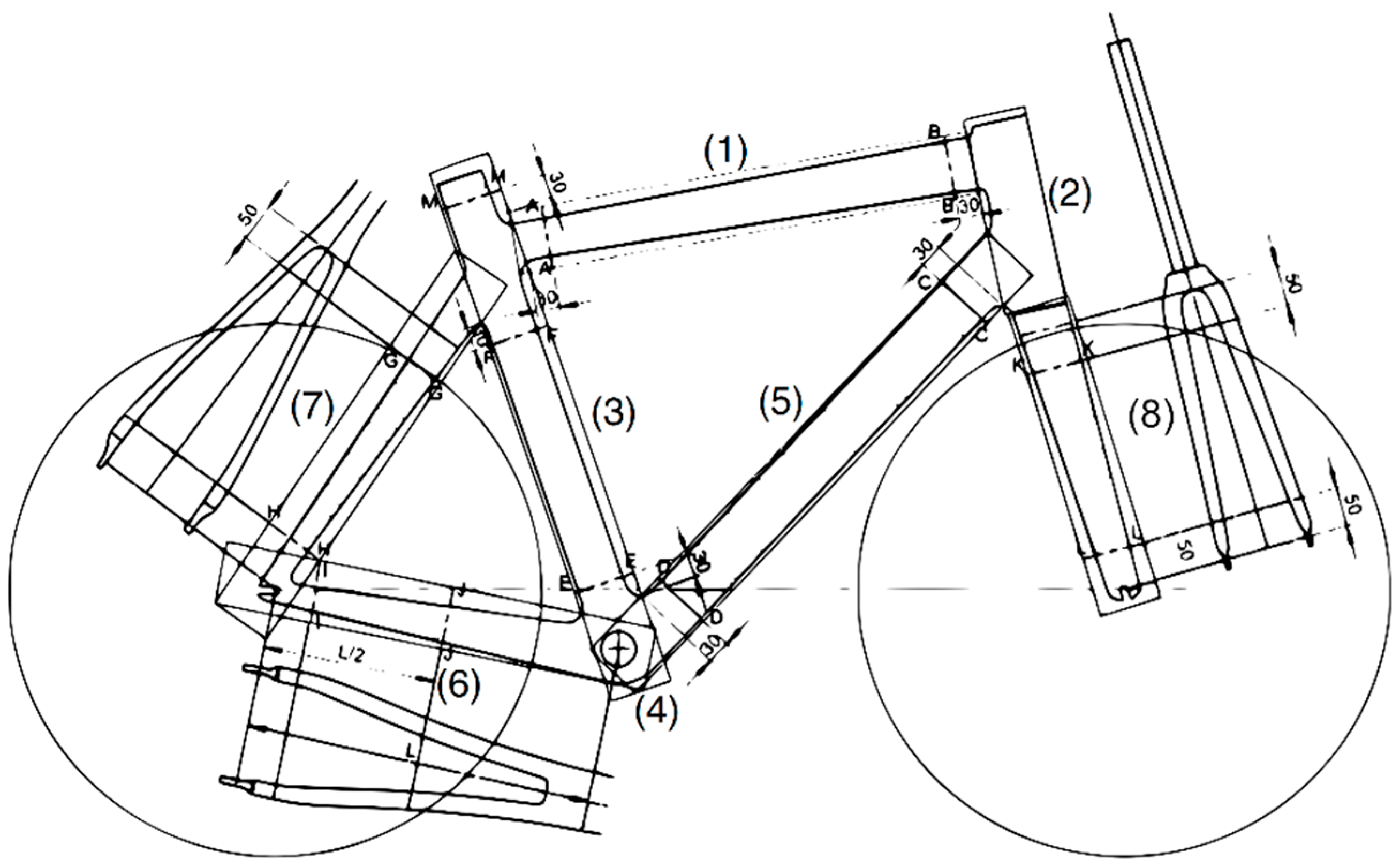
For the frame geometry, it was observed that the most common frame [21] is the so-called “diamond” frame shape which is defined by the Union Cycliste Internationale (UCI, Aigle, Switzerland) [22] and visible in Figure 1. It consists of a top tube (1) which is connected to the head tube (2) for the steering and the seat tube (3), where the seat post and saddle is mounted. At the bottom of the seat tube, the crankshaft (4) can be found and an additional down tube (5) connects it to the head tube as well. The rear wheel is mounted with the chain stays (6) at the bottom and the seat stays (7) at the top (one at each side). The front wheel is attached to the fork arms (8), which, itself, is attached to the head tube. This kind of shape can be found on more than 94% of bicycles, including the variation that the top tube is lowered to enable easier mounting [21]. Wheel size diameters are normally in the range of 24 to 29 inches with a tire width between 30 and 60 mm [23].
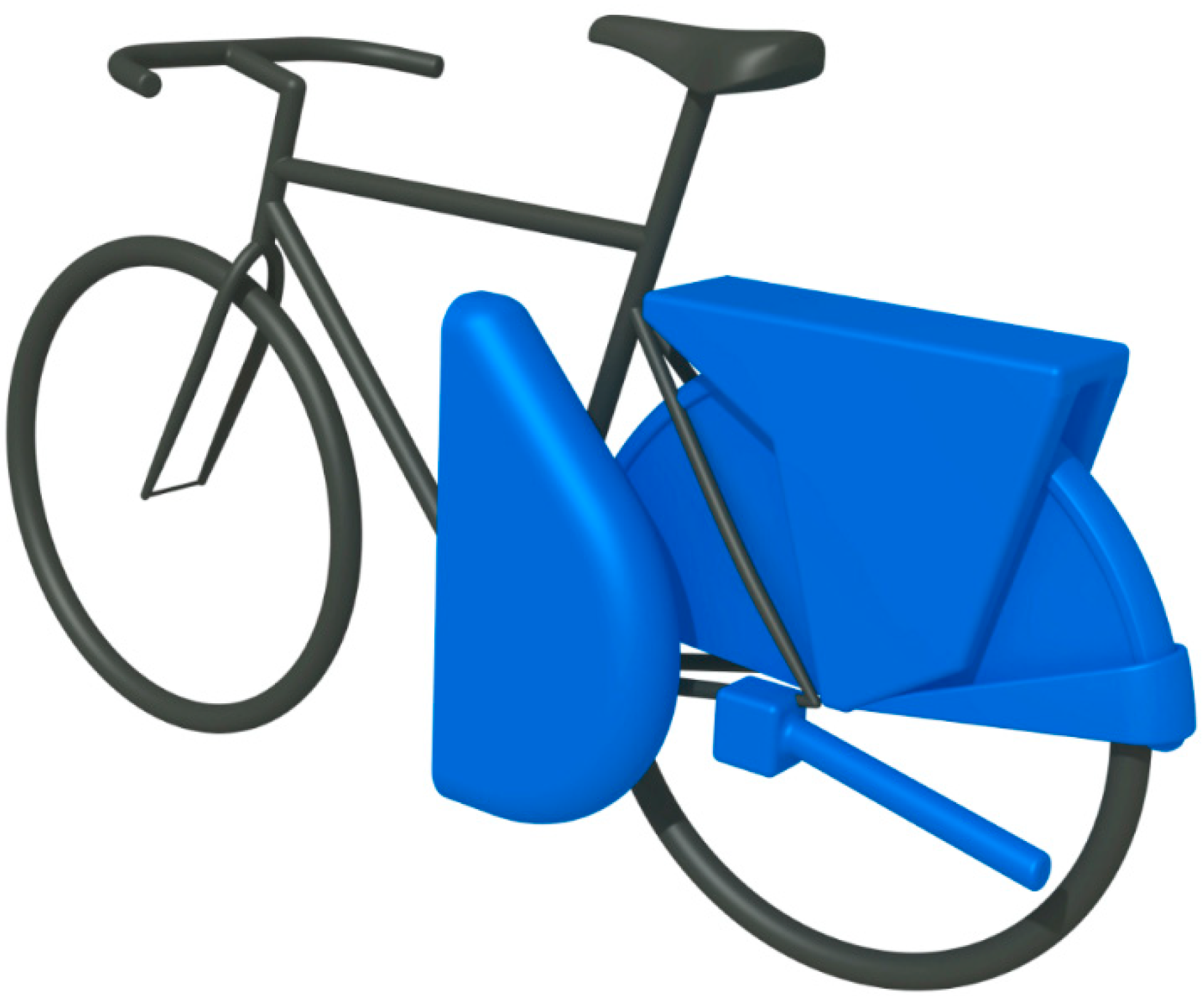
Additionally, there can be various add-ons, like mudguards, spoke guards, pannier rack, a side-stand or other devices mounted on a bicycle, but also the space in which the cyclist’s legs are moving is not usable. For this, no clear numbers for a distribution can be found, but an average case can be assumed. With a simple observation and measurement of about twenty bicycles, areas were defined on the rear wheel, which are normally occupied, as is it illustrated in Figure 2. Only the rear wheel and centre was selected and the front area discarded, as a mounting on the rear would have the lowest impact on the driving dynamics.
The next step was to define a target customer group based on their requirements. It was concluded that an electrification solution is more appropriate for commuters and entry-level leisure cyclists, as other users would be willing to spend higher amounts to obtain a bicycle that is more suitable for their individual applications. Within this group, customer expectations and wishes where analysed from existing publications. It was found that a major reason for people not to buy electric bicycles is that they are too expensive. In addition, the image that it is a support for the elderly, efforts for charging, and no charging place were named [3]. All these aspects can be addressed with a conversion kit, where only the unit has to be paid for, the bicycle style can follow individual preferences and it easily can be detached and brought home for charging. Another publication indicated that an ease of use, ease of transport, and high reliability are important to the targeted customers [24].
In conclusion, it was defined that the target customers already own a bicycle, are interested to ride (partially) electrically for low or medium distances with ease of use. For current e-bikes, they dislike the high purchasing prices or low quality, which are often too heavy and are not safe to park. Current conversion kits are not popular as they are too complex to install and mostly permanent mounted.
With this data, idea generation was started regarding how a unit could work, which would fulfil the requirements of this target customer group. The initial stage was to find different mechanisms of how the propulsive forces of a conversion kit can be engaged to accelerate a bicycle. These were thought of with a strong emphasis on integration for the majority of bicycle frames. Initial ideas focused at the rear tire, sprockets, chain, crank, pedals, and the road itself to design a suitable propulsive mechanism. Seven initial concepts were prototyped in a simple way to develop a better understanding, especially on the usability and driving dynamics behaviour, as these are otherwise difficult to evaluate:
- Friction roller at the rear wheel
- Trailer wheel on the road behind the bicycle
- Sprocket drive with extra chain
- Sprocket drive with matching counter sprocket
- Sprocket drive with wheel chain ring
- Chain drive with second, inverse form-fit chain
- Chain drive with extra sprockets
However, the large variety of frames and limited unobstructed areas decrease the options drastically. All the chain-driven options, even though initially promising, could not be investigated further, as such a solution would not work with derailleur gears, which can be found on a large share of bikes. A replacement of the wheels would be too permanent and cannot solve the charging problem. Moreover, solutions at the crankshaft and sprockets are always difficult to mount, as the resulting force requires a fitting bracket and, therefore, becomes permanent. To fulfil the other aspects of the target customer, the battery and electronics must be integrated. In addition, the sensor for pedal movement must be within the unit without the typical crankshaft-mounted cadence sensor, as used for many other conversion kits. Moreover, the agility of the bike should not be compromised.
4. Implementation
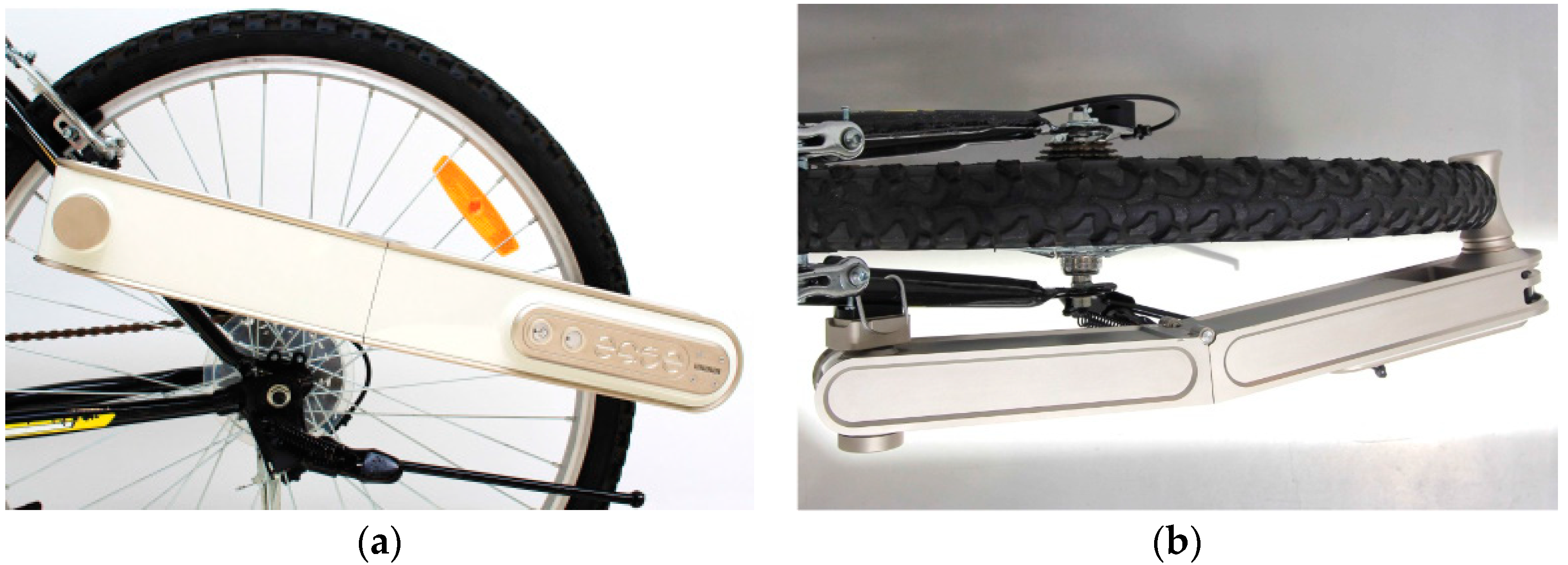
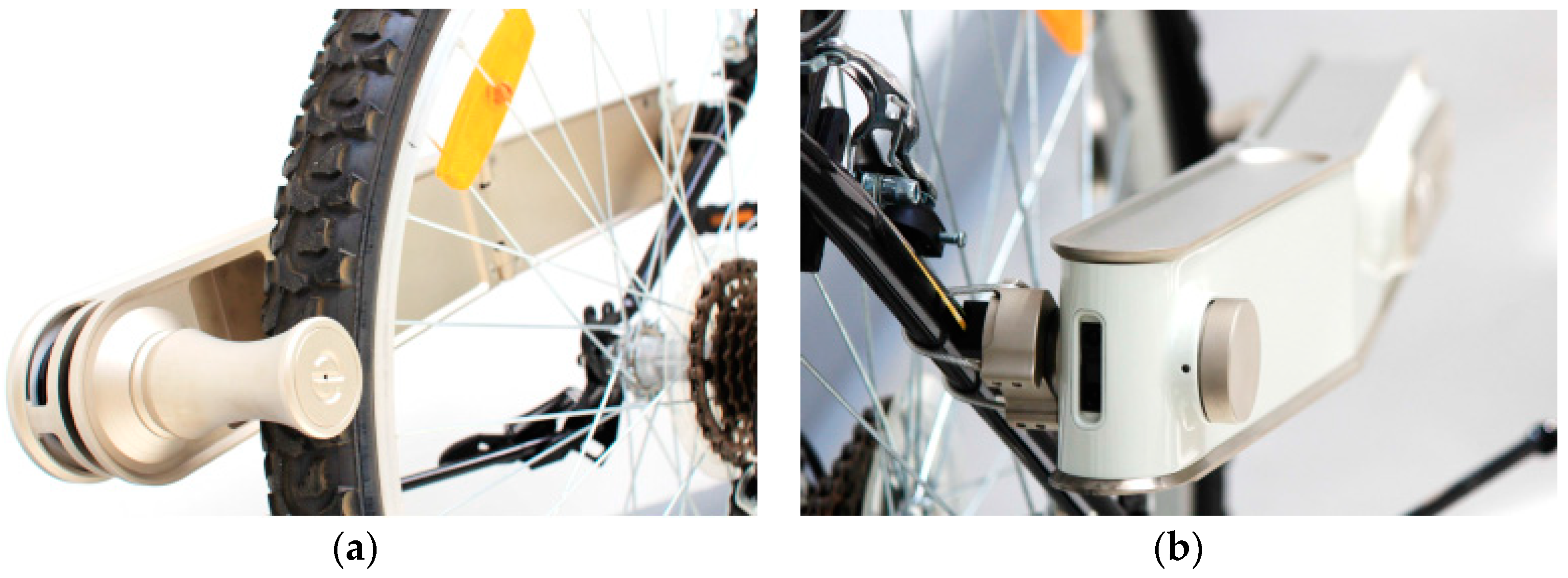
An evaluation with the factors of the target customer as a reference showed that a design with a friction roller on the rear wheel behind the ending of a possible mudguard (Option 1) was the most suitable approach amongst the ideas as this area is usually accessible. A one-sided application (Figure 3a) was identified as beneficial as it would make the mounting easier for a single person and also requires less alignment. Mounting can be achieved on one of the seat stays as long as the bike is following the most common “diamond” frame shape. With a symmetric design, the mounting side can be chosen in case one side has an uncommon attachment, like a lock. For bikes with a luggage carrier there is an additional space requirement between the wheel and the unit to allow additional structural tubes from the luggage carrier. This is accommodated by a slight curve/bending of the unit (Figure 3b). In this design configuration, the roller pulls itself towards the tire surface and, thus, enhances the contact pressure and friction. This mechanism, therefore, minimizes the slip between the tire and the roller without the need of an additional added weight of the unit to increase friction (Figure 4a).
The required sensing of pedal movement is implemented with a sensor, which measures the distance from a fixed point on the device to the cyclist’s leg over time. With the intended mounting position as shown in Figure 3 and Figure 4, this is made possible with a proximity sensor located at the very front of the device as seen in Figure 4b. The nature of the sensor does not require any special label or marking on the cyclist’s leg and works over a wide range of reflectivity values. With this configuration, a pedal movement, including its frequency, can be determined with high accuracy and is used to provide an input signal for the motor controller and, therefore, the assisting motor power.
The prototype consists of a unit that is foldable in the middle. In the front part, there is one battery pack with three Li-polymer pouch bag batteries in series, the mounting unit, and the proximity sensor. The mounting unit consists of a rubber sleeved cable loop that can be hooked around the seat stay. By turning a knob, the circumference of the cable loop can be adjusted to tighten the mounting, as shown in Figure 2a. This mechanism thereby allows the unit to be mounted on any kind of tube, independent of its cross-section and shape. The mounting unit also has the ability to rotate to accommodate different seat stay tube angles and to ease the installation process. The rotation could allow the unit to ‘bounce’ off the tire in certain situations such as driving down a curb. To minimize this effect, a rotational damper is included on the axis of the mounting unit.
The rear part holds a second identical battery pack with another three cells in series, and the motor, including the friction wheel and the electronics. All six battery cells are connected in series to achieve a nominal voltage of 22.2 V and a total capacity of 10 Ah. A battery management system controls several battery functions and can switch off the energy supply in case of a safety-inflicting situation. In addition, the integrated electronic hardware consists of a DC/DC converter to supply all auxiliaries and a microcontroller platform based on an ATmega328 created by Atmel (San Jose, CA, USA). A rear light, which also functions as a brake light if a certain deceleration value is reached, is located at the very rear of the housing. An inertial measurement unit (IMU) is used to recognize on which side of the bicycle the unit is mounted.
The motor is a standard brushless DC (BLDC) electric motor in an “outrunner” configuration, where the rotor with the magnets is turning around the static coils. Its integrated cooling features are enabled with openings at the rear part of the housing, where fresh air can be drawn from the opening for the mounting unit when folded and hot air is blown out through a gap next to the rear light (Figure 4a). The power for the three-phase motor comes from a microcontroller-enabled three-phase full bridge MOSFET inverter. The power electronics are integrated behind a separated metal structure to ensure the waste heat is dissipated to the ambient environment without warming up the main housing and, therefore, the batteries. This ensures longer battery life.
The friction roller is mounted directly on the rotor of the motor and is not coupled to any gears. Two additional bearings support the loads on the motor axle. The roller itself has a blank surface, as the friction is enabled through the forces that pull the roller on the tire. With the avoidance of a special surface, wear and tear can be minimised. The roller profile is designed to be of a concave cylinder shape, which allows the roller to self-center on the round surface of the tire. As the chosen motor works more efficiently at higher speeds, smaller diameters of the roller are preferred. In this case, a roller diameter of 30 mm is selected.
The normal operation pattern for this conversion kit would first be to mount it on the bicycle and then switching it on. The device would then be ready and awaits the cyclist to start pedaling. A feedback from the motor lets the controller know at what speed the bike is moving. This is independent from the wheel size as the speed of the outside of the roller is the same as the road speed—as long as there is no slip. Only once a minimum speed of 2 km/h is reached the controller starts to read the signal from the distance sensor to fully avoid false powering. The reading of the sensor is analyzed over time using a Fast Fourier Transformation (FFT) to identify typical pedaling patterns by calculating the control parameters mean, standard deviation, and frequency. The mean value is used for detecting the relative position to the sensor, while the standard deviation is an important parameter for a fast detection when pedaling is stopped. The frequency of a periodic movement correlates to the speed of the pedal movement. If these values are within a defined range, a pedal movement has a very high probability. The details of this detection are too extensive for this publication and are treated separately. If pedaling is detected, the motor is powered according to the current speed and level of assistance. If the speed is over 25 km/h or the pedaling stops, the motor is switched off immediately. With the measurement of current and voltage, it can also be ensured that the mean motor power is within the legally-allowed 250 W.
Through this design approach, a functional prototype proved to be easy to install, complying with the legal requirements and being able to be used on most existing off-the-shelf bicycles. Therefore, the principal requirements of the target customer are fulfilled.
5. Experiments and Testing
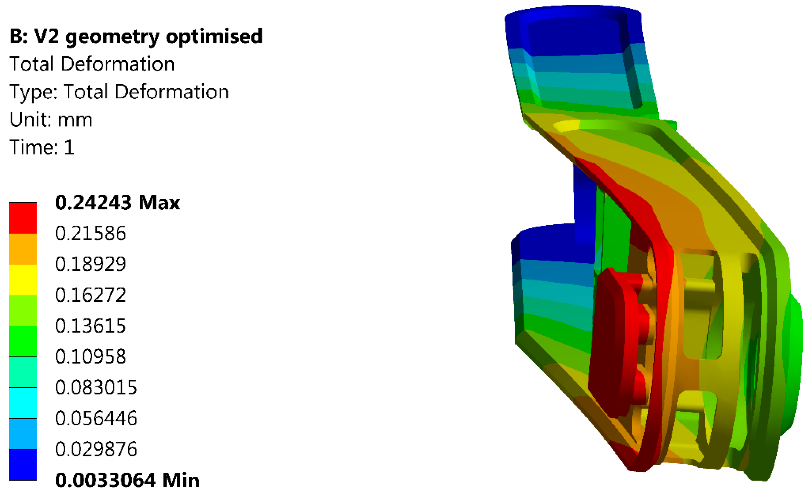
With a functional prototype, several requirements can be fully tested. Nevertheless, due to the lack of a proper test stand for bicycles, some tests have to be conducted in a simulated environment. A major concern is the stiffness and structural strength of the enclosure, since it has to bear the weight of the battery and it is only supported at the mounting point and the tire. There will be additional stresses on the enclosure when the motor is active, as this pulls the unit down along the tire. Here, simulations with the finite element method (FEM) using ANSYS Workbench (Canonsburg, PA, USA) are conducted to visualize the deformation and, therefore, the stress. Simulations have shown that the deformation is not in a critical range for an aluminum, C-shaped housing with a high factor of safety (FOS) of more than eight, as can be seen in Figure 5.
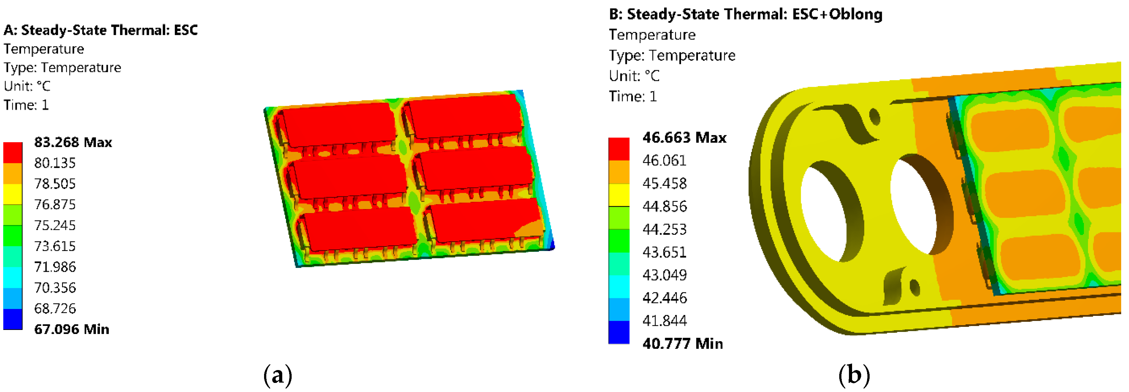
Another topic analyzed with simulations is the thermal stress caused by the power electronics, which are located behind the separated metal structure on the outer surface. With the installed power MOSFETs under maximum electrical load, a total loss of 2.33 W was calculated using the data provided in the datasheet [25]. With another ANSYS Workbench simulation, a crucial heat up of the electronics of more than 80 °C in an ambient temperature of 25 °C was calculated (Figure 6a). While this temperature is still acceptable for the MOSFETs, it would also heat up the batteries next to it, which age faster at higher temperatures. However, with a thermal coupling of the electronics to the heatsink, the simulation shows a more moderate heating of less than 47 °C, as seen in Figure 6b.
To ensure legal usage, the three main requirements from EN15194 have to be covered as well [8]. The legal speed of 25 km/h is ensured with the motor feedback, which has a very high resolution due to the small diameter of the roller compared to the wheel. This was verified by the usage of a speedometer, where the motor switches off if the bicycle is driven faster manually, as is required in the standard. The average input motor power is measured by the controller with the battery voltage and current consumption over the current sensor (). As the standard EN15194 defines the motor power output to be less than 250 W, due to efficiency losses if the input is 250 W, the output must always be less and, therefore, fulfils the standard. More challenging is the pedal detection, which requires that the cut-off distance, when the cyclist stops pedaling, shall not exceed 2 m. For a bicycle, driving at 25 km/h, this equals a cut-off time of 0.288 s in the worst case. However, with an external cadence sensor it is possible to verify that the controller would always switch off the motor within the required time using the mentioned sensing approach.
An often-mentioned problem with friction rollers is the additional abrasion of rubber on the tire. Here the surface of the roller on the tire and its shape are critical parameters. For many rollers from existing products, the surface is made rough by an added or engraved surface. In addition to the fact that this is shortening the required maintenance intervals of the roller, as such a surface is wearing off, it also increases the abrasion of the tire. Nevertheless, for many units it is required, as the roller is not pressing itself on the tire strong enough to ensure the friction. In the case of the demonstrated concept it is not required as the unit is pulling itself against the tire during motor operation. In spite of that, a smooth roller surface still causes some additional abrasion, mainly due to a not totally perpendicular running of the roller, which causes relative velocities (not all areas of the roller running at the exact same speed as the tire due to the varying diameter of the required concave shape and, therefore, rub each other). This is solved by a concave design of the roller with a tilted motor axis of 9° and a 2° conical shape as seen in Figure 7a,b.
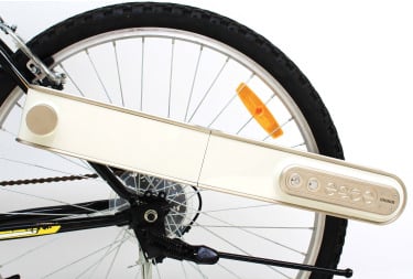
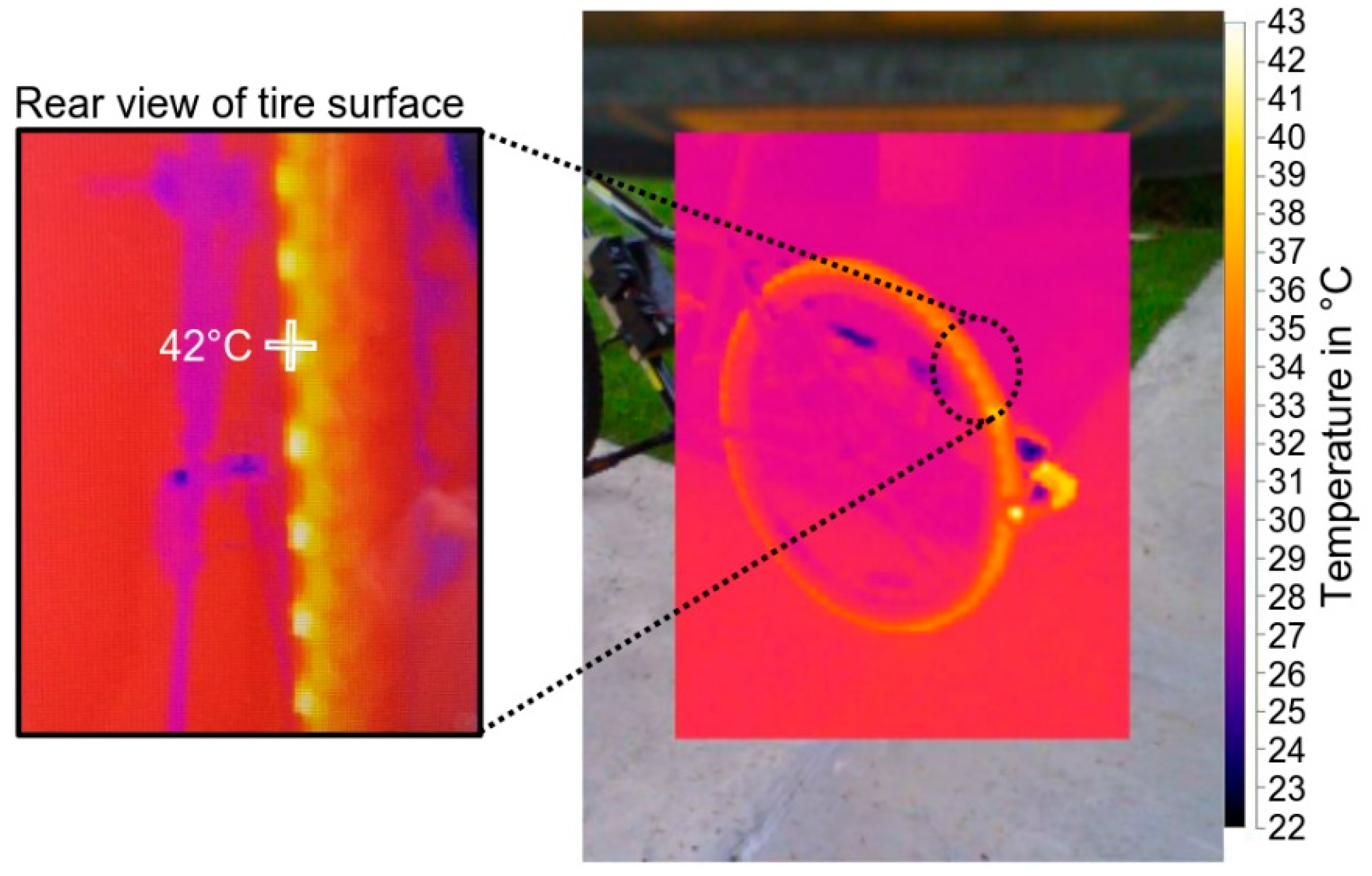
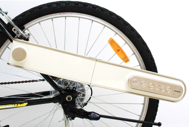
To verify the abrasion of the friction roller with a smooth surface, the temperature of the tire surface is measured. With different rollers, the same distance with no pedal support is driven and, afterwards, the temperature of the tire is measured (Figure 8). With the optimized shape, the lowest temperature increment is seen. It has to be mentioned that the tire must be properly inflated. With an air pressure much lower than rated, the unit presses itself so strongly against the surface that the tire deforms. This causes relative velocities again, which heat up the tire and, therefore, cause abrasion.
The last experiments were conducted to analyze the slippage of the wheel if the friction parameters are changed due to moisture or particles (sand, dust) on the tire. Here it was noticeable that sometimes the roller is losing friction in specific situations, like wet sand. This causes the unit to no longer be pressed against the tire, which, again, causes the motor to spin faster. At the maximum allowed roller speed, the motor is switched off and, therefore, gains friction again, which creates a self-retaining function. Detailed measurements for this behavior are not yet conducted due to the lack of a proper bicycle test stand.
6. Results
With the current implementation, it is possible to realize an electrification kit that can be mounted on most conventional bicycles. The prototype was tested on about 30 different bicycle types. The results showed that the prototype worked on the majority of the tested bicycles, even including unconventional bikes, like tandems. Problems were, however, faced with very small bikes, like foldable bicycles. Firstly, the length of the unit is too long, and also very often the frame comes in unusual shapes, not following the diamond shape. A solution for this could be to work with a different mounting mechanism, which can clamp around the seat post, but this is not implemented or tested. Also verified is the usage of different attachments, like brakes, additional cables, mudguards, skirt protectors, and bags. Only in one case a luggage carrier with a special extension for a child seat was standing out too widely during the tests and, therefore, made mounting inapplicable. The friction roller was able to run with different tire surfaces. Even tires with rough profiles for off-road usage worked, but resulted in an audible noise generation. Slippage was not noticeable, even on wet tires, and only with additional sand it would slip, but self-retain due to the speed limit of the motor.
The pedal detection was found to be working sufficiently well for a prototype. While the initial detection takes two to three rotations of the pedal before the activation of the motor, for stopping, the motor switches off within the required 288 ms. Due to the various requirements and verifications by the algorithm it is not possible to falsely trigger the activation with hand movement or similar. Further improvement is possible with better algorithms on the detection in order to activate even faster. Additionally force/effort detection could provide increased electrical assist while cycling up steep slopes. Currently, the support uphill might be felt insufficient, while during a downhill ride, the rider reaches the speed limit of 25 km/h too fast.
For such a solution to be successfully implemented on the market, costs would play an important role. A first complete prototype was built for less than 2000 EUR in terms of material costs. This is still largely influenced by the expensive, individual 3D-printed and milled housing parts along with the components that were sourced from expensive retail sellers. If the quantity for the same prototype with the same components is raised to a small series of 100 pieces, the component price per piece can be reduced below 640 EUR according to offers from suppliers of the components. With an analysis of the current market in Germany as a reference, the average price for bicycles in 2015 was 685 EUR [3] including the higher-priced electric bicycles. This price region should be considered as a maximum target price, as the unit should not be more expensive than the average bicycle. Thus, the defined requirements for the target customer can all be fulfilled with the proposed concept.
7. Conclusions
A fully-functional prototype unit with the project name “ease” is built up so that it can be tested. It weighs around 3.5 kg and is suitable for a range of up to 50 km. A patent is applied for and currently in a pending status. It is proven that the system is working in a legal way without any additional attachments, e.g. sensors, mounting brackets, etc., and can be attached/detached in a few seconds. In addition, it was possible to test the device on many bicycles to ensure compatibility. Friction losses in the form of slipping are minimal due to the special geometry of the unit. Therefore, it could enable more people to equip existing bicycles with an electric support without purchasing a completely new bike. This could make more people use bicycles instead of other modes of transportation for their daily commutes, which could have a positive impact on traffic congestion in larger cities.
Author Contributions
F.R. was mainly responsible for developing the concept and authoring the article. M.M. and S.S. were the executing force of the development and implementation of the concept and their work contributed to the article. M.L. supervised and evaluated the manuscript.
Funding
This work was financially supported by the Singapore National Research Foundation under its Campus for Research Excellence and Technological Enterprise (CREATE) programme.
Conflicts of Interest
The authors declare no conflict of interest.
References
- Pfaffenbichler, P.C. Verkehrsmittel und Strukturen [Transportation and Structures]. Verkehr Mob. 2001, 3, 35–41. (In German) [Google Scholar]
- Confederation of the European Bicycle Industry. European Bicycle Industry Market Profile (BIMP): 2014 Statistics. 2015. Available online: www.conebi.eu (accessed on 24 June 2017).
- Sinus Markt- und Sozialforschung GmbH. Fahrrad-Monitor Deutschland 2015: Ergebnisse Einer Repräsentativen Online-Befragung [Bicycle Survey GERMANY 2015: Results of a Representative Online Survey]. 2015. Available online: https://www.bmvi.de/SharedDocs/DE/Anlage/VerkehrUndMobilitaet/Fahrrad/fahrrad-monitor-deutschland-2015.pdf?__blob=publicationFile (accessed on 24 June 2017). (In German).
- Witt, P. Motorräder [Motorbikes], 1st ed.; Verlag Technik: Berlin, Germany, 1989; p. 7. ISBN 3-341-00657-5. (In German) [Google Scholar]
- Tragatsch, E. The Illustrated Encyclopedia of Motorcycles; New Burlington Books; Quarto Publishing: London, UK, 1988; p. 260. ISBN 0-906286-07-7. [Google Scholar]
- Brüsch, S. Pedelecs: Fahrzeuge der Zukunft [Pedelecs: Vehicles of the Future]; Heidelberg University: Heidelberg, Germany, 1999. (In German) [Google Scholar]
- Hurst, D.; Gartner, J. Executive Summary: Electric Bicycles: Global Market Opportunities, Barriers, Technology Issues, and Demand Forecasts for E-Bicycles, Pedal-Assist Bicycles, and E-Bicycle Batteries and Motors. 2013. Available online: http://www.navigantresearch.com/wp- assets/uploads/2013/03/EBIKE-13-Executive-Summary.pdf (accessed on 24 June 2017).
- Deutsches Institut fuer Normung (DIN). prEN 15194: Cycles—Electrically Power Assisted Cycles—EPAC Bicycles; Deutsches Institut fuer Normung (DIN): Berlin, Germany, 2015. [Google Scholar]
- Zichner, M. Electric Bicycle Drive. U.S. Patent D750,999, 8 March 2016. [Google Scholar]
- Drive & Innovation GmbH & Co. KG. RELO. 2013. Available online: http://relodrive.com/ (accessed on 24 June 2017).
- Muetze, A.; Tan, Y.C. Electric Bicycles—A performance evaluation. IEEE Ind. Appl. Mag. 2007, 13, 12–21. [Google Scholar] [CrossRef]
- Outram, C.; Ratti, C.; Biderman, A. The Copenhagen Wheel: An innovative electric bicycle system that harnesses the power of real-time information and crowd sourcing. In Proceedings of the Exhibition on Ecologic Vehicles & Renewable Energies (EVER), Monte-Carlo, Monaco, 25–28 March 2010. [Google Scholar]
- Superpedestrian Inc. Copenhagen Wheel: The Bicycle Revolution Is Coming to Your Streets. 2015. Available online: https://superpedestrian.com/ (accessed on 24 June 2017).
- Burtov, M.; Decker, D.; Coltof, G. Self-Powered Planetary Orbital Wheel Assemblies. U.S. Patent App. 14/843,706, 3 October 2016. [Google Scholar]
- Zhao, S.Y. UrbaNext. 2017. Available online: https://www.kickstarter.com/projects/934648866/urbanx-convert-any-bike-to-an-electric-bike-in-60 (accessed on 24 June 2017).
- GP Motion GmbH. Add-e. 2015. Available online: http://www.add-e.at/en/home/ (accessed on 24 June 2017).
- Go-e GmbH. Go-e ONwheel. 2015. Available online: http://go-e.bike/en/ (accessed on 24 June 2016).
- Nemanis, G. Electric Friction Bicycle Drive. WO Patent App. PCT/LT2014/000,010, 15 January 2015. [Google Scholar]
- International Nickel Study Group. The Global E-bike Market. In INSG Insight 23. 2014. Available online: http://www.insg.org/docs/INSG_Insight_23_Global_Ebike_Market.pdf (accessed on 25 April 2016).
- Weiss, E.; Illek, G. Mobil und Sicher mit Elektrofahrrädern: Endbericht [Agile and Safe with Electric Bicycles: Final Report]. 2013. Available online: https://www.bmvit.gv.at/verkehr/ strasse/sicherheit/fonds/vsf/downloads/21_mobil_sicher_ef.pdf (accessed on 25 April 2016). (In German).
- Zweirad-Industrie-Verband e.V. Zahlen—Daten—Fakten zum Deutschen Fahrradmarkt 2015 [Numbers—Data —Facts about the German Bicycle Market 2015]; ZIV Wirtschaftspressekonferenz: Berlin, Germany, 2016. (In German) [Google Scholar]
- Union Cycliste Internationale. Clarification Guide of the UCI Technical Regulation. 2016. Available online: http://www.uci.ch/mm/Document/News/Rulesandregulation/16/51/61/ClarificationGuideoftheUCITechnicalRegulation-15.01.2016-ENG_English.pdf (accessed on 5 May 2016).
- Schwalbe North America: Tire Dimensions. 2016. Available online: http://www.schwalbetires.com/tech_info/ tire_dimensions (accessed on 5 May 2016).
- Budde, A.; Neupert, H. ExtraEnergy: Pedelc E-Bike Magazin[e]. 2015. Available online: https://issuu.com/extraenergy/docs/magazin-12_v1_3-web (accessed on 5 June 2016).
- International Rectifier. Data Sheet No. PD-60043 Rev.O IR2101(S)/IR2102(S)& (PbF) High and Low Side Driver. 2004. Available online: http://www.irf.com/product-info/datasheets/data/ir2101.pdf (accessed on 5 November 2016).
Figure 1.
General illustration of the positioning of frame elements by the Union Cycliste Internationale for competition bicycles [22].
Figure 1.
General illustration of the positioning of frame elements by the Union Cycliste Internationale for competition bicycles [22].

Figure 2.
Potential obstructed area (blue) on a reference bicycle model.

Figure 3.
(a) Side view of the prototype; and (b) top view of the prototype.

Figure 4.
(a) Friction roller engagement; and (b) mounting and proximity sensor.

Figure 5.
Contour plot showing the total deformation of the two housing parts in millimeters, if the unit is fixed at its mounting location and loaded with the maximum expected stress.
Figure 5.
Contour plot showing the total deformation of the two housing parts in millimeters, if the unit is fixed at its mounting location and loaded with the maximum expected stress.

Figure 6.
(a) Contour plot of temperature for bare electronics in degrees Celsius at thermal equilibrium; and (b) contour plot with the heatsink.
Figure 6.
(a) Contour plot of temperature for bare electronics in degrees Celsius at thermal equilibrium; and (b) contour plot with the heatsink.

Figure 7.
(a) Cross-section of tire (red) and roller (blue) indicating the shape and angle for the roller. (b) Relative velocities of the conical shape, showing a 2° conicity and a 9° tilted motor axis.
Figure 7.
(a) Cross-section of tire (red) and roller (blue) indicating the shape and angle for the roller. (b) Relative velocities of the conical shape, showing a 2° conicity and a 9° tilted motor axis.

Figure 8.
Temperature distribution at the rear tire surface with non-optimal roller geometry measured at an ambient temperature of 31 °C and causing an increase tire temperature to 42 °C.
Figure 8.
Temperature distribution at the rear tire surface with non-optimal roller geometry measured at an ambient temperature of 31 °C and causing an increase tire temperature to 42 °C.

Table 1.
Summary of the comparison of the different existing e-bike conversion solutions based on the information found in the quoted sources in the text.
Table 1.
Summary of the comparison of the different existing e-bike conversion solutions based on the information found in the quoted sources in the text.
| Coverage | Install. | Sensor | Efficient | Detach. | Battery | Reliab. | Price | |
|---|---|---|---|---|---|---|---|---|
| Crankshaft | o | -- | - | + | - | + | + | - |
| Wheel hub motor | - | - | - | + | - | + | + | o |
| Wheel hub unit | - | o | + | + | - | - | + | o |
| Friction roller | o | -- | - | o | - | + | o | o |
| Friction unit | o | + | - | o | + | + | o | o |
© 2018 by the authors. Licensee MDPI, Basel, Switzerland. This article is an open access article distributed under the terms and conditions of the Creative Commons Attribution (CC BY) license (http://creativecommons.org/licenses/by/4.0/).
Share and Cite
MDPI and ACS Style
Roemer, F.; Mrosek, M.; Schmalfuss, S.; Lienkamp, M. New Approach for an Easily Detachable Electric Drive Unit for Off-the-Shelf Bicycles. World Electr. Veh. J. 2018, 9, 37. https://doi.org/10.3390/wevj9030037
AMA Style
Roemer F, Mrosek M, Schmalfuss S, Lienkamp M. New Approach for an Easily Detachable Electric Drive Unit for Off-the-Shelf Bicycles. World Electric Vehicle Journal. 2018; 9(3):37. https://doi.org/10.3390/wevj9030037
Chicago/Turabian StyleRoemer, Felix, Marius Mrosek, Simon Schmalfuss, and Markus Lienkamp. 2018. "New Approach for an Easily Detachable Electric Drive Unit for Off-the-Shelf Bicycles" World Electric Vehicle Journal 9, no. 3: 37. https://doi.org/10.3390/wevj9030037