Vehicle Level Control Analysis for Voltec Powertrain
by
 ,
,
Namdoo Kim
1,* ,
,
Sungwook Choi
2,
Jongryeol Jeong
1,
Ram Vijayagopal
1,
Kevin Stutenberg
1 and
Aymeric Rousseau
1 1
Argonne National Laboratory, 9700 South Cass Avenue, Lemont, IL 60439-4815, USA
2
School of Mechanical Engineering, Sungkyunkwan University, 25-2 Suwon-si, Seoul 03063, Korea
*
Author to whom correspondence should be addressed.
World Electr. Veh. J. 2018, 9(2), 29; https://doi.org/10.3390/wevj9020029
Submission received: 2 May 2018
/
Revised: 3 July 2018
/
Accepted: 20 July 2018
/
Published: 2 August 2018
(This article belongs to the Special Issue Selected Papers from The 30th International Electric Vehicles Symposium and Exhibition (Stuttgart, Germany))
Abstract
:The next generation of the Volt vehicle with the new “Voltec” extended-range propulsion system was introduced into the market in 2016. The second-generation Volt’s powertrain architecture provides five modes of operation, including two electric vehicle operations and three extended-range operations. Vehicle testing was performed on a chassis dynamometer set within a thermal chamber at the Advanced Powertrain Research Facility at Argonne National Laboratory. The study first focused on assessing the improvement of the new Voltec system by comparing the system efficiency with the previous system. Second, control behavior and performance were analyzed under normal ambient temperature to understand the supervisory control strategy on the Voltec system based on the test data. The analysis focused on the engine on/off strategy, powertrain operation mode, energy management, and engine operating conditions. Third, test data from the control analysis were used to summarize the vehicle control logic.
1. Introduction
This paper presents an analysis of the powertrain system and the vehicle level control strategies of the 2016 Chevrolet Volt based on dynamometer test data. Argonne National Laboratory (Argonne) has been working with the U.S. Department of Energy (DOE) and the automotive industry to provide informative analysis results of advanced vehicles to the public [1,2,3,4,5,6]. For this purpose, Argonne’s Advanced Powertrain Research Facility (APRF) is equipped with two-wheel and four-wheel drive dynamometers, and vehicle performance characteristics, such as fuel economy and emissions, are evaluated at the bench dynamometers. For many years, Argonne has tested, analyzed, and validated the models for conventional, hybrid electric, plug-in hybrid electric, and battery electric vehicles (EVs), including their thermal aspects, and is continuing its efforts to provide more analysis results for advanced vehicles.
The Volt vehicle is the first electric range-extended vehicle to be manufactured on a large scale; it went on sale in December 2010. Its successful introduction to the worldwide vehicle market, especially in the U.S. market, has resulted in the world’s all-time best-selling plug-in hybrid vehicle as of December 2016. The latest version of the vehicle, the second generation, was debuted at the January 2015 North American International Auto Show and was available in the market in October 2015, as a 2016 model year (MY) [7].
This paper presents an analysis of the second generation of the Volt powertrain system, called the new Voltec system, by comparing its system efficiency with the previous system. The supervisory control strategy on the MY 2016 Volt is introduced by an analysis of test results. In order to understand control behavior, the supervisory control concepts are divided into three parts—mode decision, energy management, and component control. This study was limited to the control analysis of the 2016 Volt, and the modeling techniques for model validation are not included in this paper, although vehicle modeling is also one of the strengths of Argonne [8]. Instead, additional studies extended to the modeling and validation are available for the vehicle.
2. The Second-Generation Volt Powertrain
Table 1 presents the main changes in the powertrain component of the MY 2016 Volt. The engine and energy storage in the new version have higher power and energy values than the powertrain components in the previous versions. Although a full comparative study between the MY 2011 and MY 2016 Volt is beyond the scope of this study, a published paper has shown that the improvement in fuel economy was due to significant design improvements, including reductions in accessory load, reduced aerodynamic, and a new propulsion system [7]. The most significant change in the powertrain configuration of the MY 2016 Volt compared to the previous version is that the vehicle has a new transaxle configuration and operation modes.
In the MY2011 Volt, two clutches (CL1, CL2) and one brake (BK) are applied in the powertrain system, which allows for multiple driving modes for the vehicle. The engine and Electric machine 2 (MG2) are connected through CL1, and the MG2 is connected to the ring gear through CL2. The ring gear is also connected to the sun gear, and the carrier is connected to the final reduction gear. By setting the engagement and disengagement of the clutches and brake, the propulsion system is driven in four modes: EV1, EV2, series, and output power-split mode.
In the MY 2016 Volt, each of the two electric machines is geared to a common main transmission shaft using an individual planetary gear set, as shown in the schematic diagram. Each electric machine is connected with a sun gear, and clutches can provide reaction torque by holding the ring gear of each planetary gear set. When the brake (BK1) and one-way clutch (OWC) are active, both electric machines can provide maximum output torque and EV acceleration as a two-motor EV mode (EV2 mode).
The second-generation Volt contains an additional planetary gear set, which is also required for a fixed gear ratio or compound power-split mode in extended-range operation. In extended-range operation, both planetary gear sets are used for input split, fixed gear and compound split mode, depending on whether the clutch or the brake in the transmission is activated. The second planetary gear set multiplies the torque from the input and both electric machines during input-split operation. The brake (BK1) activates the input-split mode and low-speed torque multiplication by holding the ring gear of the second planetary gear set. By engaging both the brake (BK1) and the clutch (CL1), the propulsion system is driven in the fixed gear ratio mode and the engine is physically connected to the wheels via fixed reduction gear. The clutch (CL1) is a rotating clutch that activates the compound-split mode by connecting the sun of the first planetary gear set to the ring of the second gear set.
2.1. Transmission Efficiency of Electrically Variable Transmission Operation
To briefly compare the new transmission system with the previous one before analyzing the test data and developing detailed models, the efficiency of the electrically variable transmission (EVT) was analyzed as a function of input speed, input torque, and speed ratio by the method introduced in our previous study [9]. This analysis is limited to when the engine is used as a power source to increase the vehicle’s range (i.e., during extended-range operation)
The power-split configurations have both all-mechanical and electromechanical paths combining the planetary gear set and two electric machines. In one path (the all-mechanical path), the power from the internal combustion engine is directly transmitted to the wheels. In the other path (the electromechanical path), the power from the engine is converted into electricity by a generator to drive the electric motor or to charge the battery. In this analysis, it is assumed that there is no power loss through the all-mechanical path and only electric machine loss is considered by using the efficiency maps of electric machines. A simplified transmission efficiency model was obtained by inserting the efficiency values of electric machines [10], assuming no battery power.
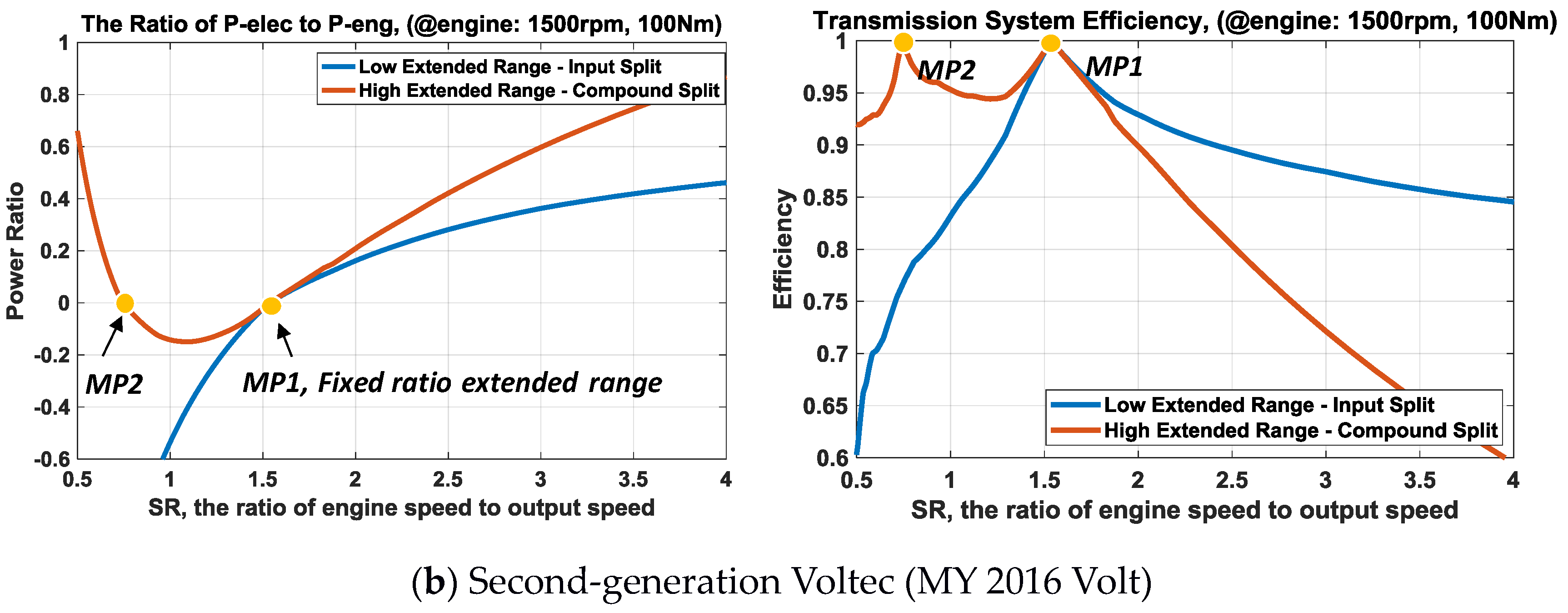
In Figure 1, the electromechanical power ratio and the transmission efficiency are plotted with respect to the speed ratio (SR) for both transaxle configurations. The power ratio is defined as the ratio of the electromechanical power to the input power, and the SR is defined as the ratio of the input speed to output speed in the transmission system. The lower the power ratio, the more power is transmitted to the all-mechanical path. Because of the high efficiency of the all-mechanical path, the system efficiency increases as more power is transmitted to the all-mechanical path. The positive sign of the power ratio means that the flow of power is transmitted from MG2 to MG1, and the negative sign is opposite.
In the first-generation Voltec, the transmission efficiency of the high SR range is relatively low because the electrical machines have relatively low efficiency. This low efficiency can be avoided by propelling the vehicle with the series mode instead of the out-split mode during extended-range operation.
In the second-generation Voltec, the electromechanical power ratio becomes zero at both mechanical points (MP1, MP2). The input-split mode is maintained until the speed ratio reaches MP1. At this point, the shift from the input-split mode to the compound split mode is carried out by the clutch and brake operations. The first mechanical point provides the ability to restrain both continuous electric machine power during cruising and peak motor power during acceleration. The fixed gear ratio (FG) comes from locking up the input-split mode, so the speed, torque, and power from the engine go through the torque multiplication of the planetary gear sets. The two-mode power-split system with one fixed gear ratio point is able to lower the requirement for electric machine power, thus allowing a further decrease in component size while still providing the power capability to achieve vehicle performance targets.
2.2. Mode Shift Strategy
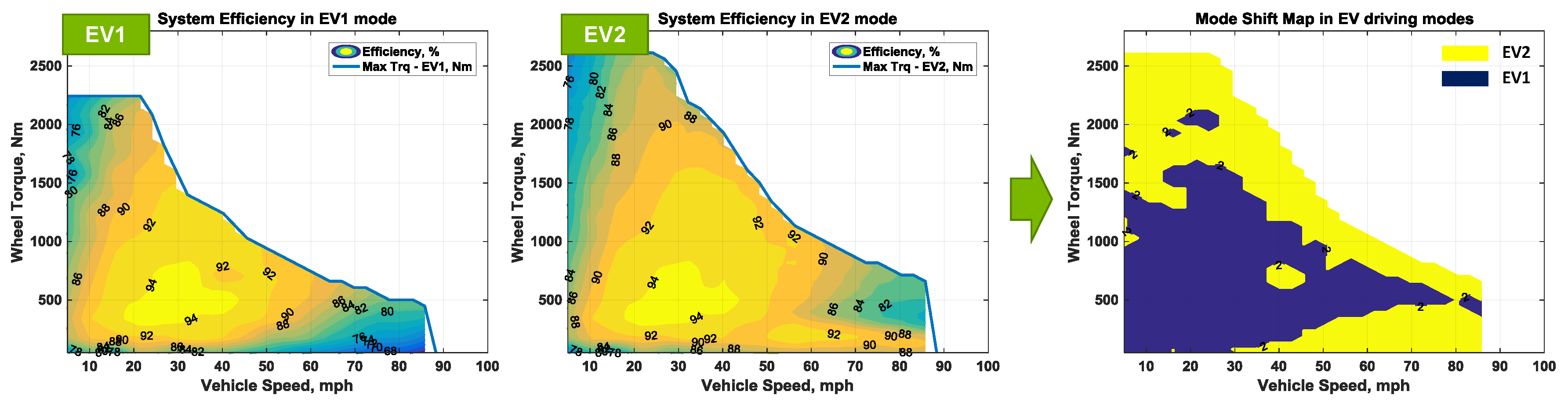
In the second-generation Voltec, the simplified system efficiency for EV drive mode was calculated by using efficiency values of electric machines as shown in Figure 2. The efficiency of the wheel torque and vehicle speed domain is defined as the traction power delivered to the axle divided by the electric power input. In EV1 operation, the vehicle is propelled using Electric machine 1 only, so the system efficiency is determined by the efficiency map of Electric machine 1 (MG1).
When operating the EV2 drive, the most efficient combination of motor input torque can be selected to meet the output speed and torque. The system efficiency for the EV2 drive is shown in the middle graph of Figure 2. With this two-motor arrangement, motor torque can be adjusted continuously for greatest tractive effort or greatest overall efficiency. Given that power is speed times torque, the power split between the two motors used to drive the vehicle is controlled by varying the motor torque. The optimal mode selection during EV driving is shown in the far right graph in Figure 2 by comparing the efficiency of EV drive modes. Although EV1 drive could cover typical driving conditions, at high torque, rising losses make it more efficient to use both electric motors to produce torque. Therefore, in EV operation, the Voltec powertrain can automatically reconfigure its power-flow between two EV modes.
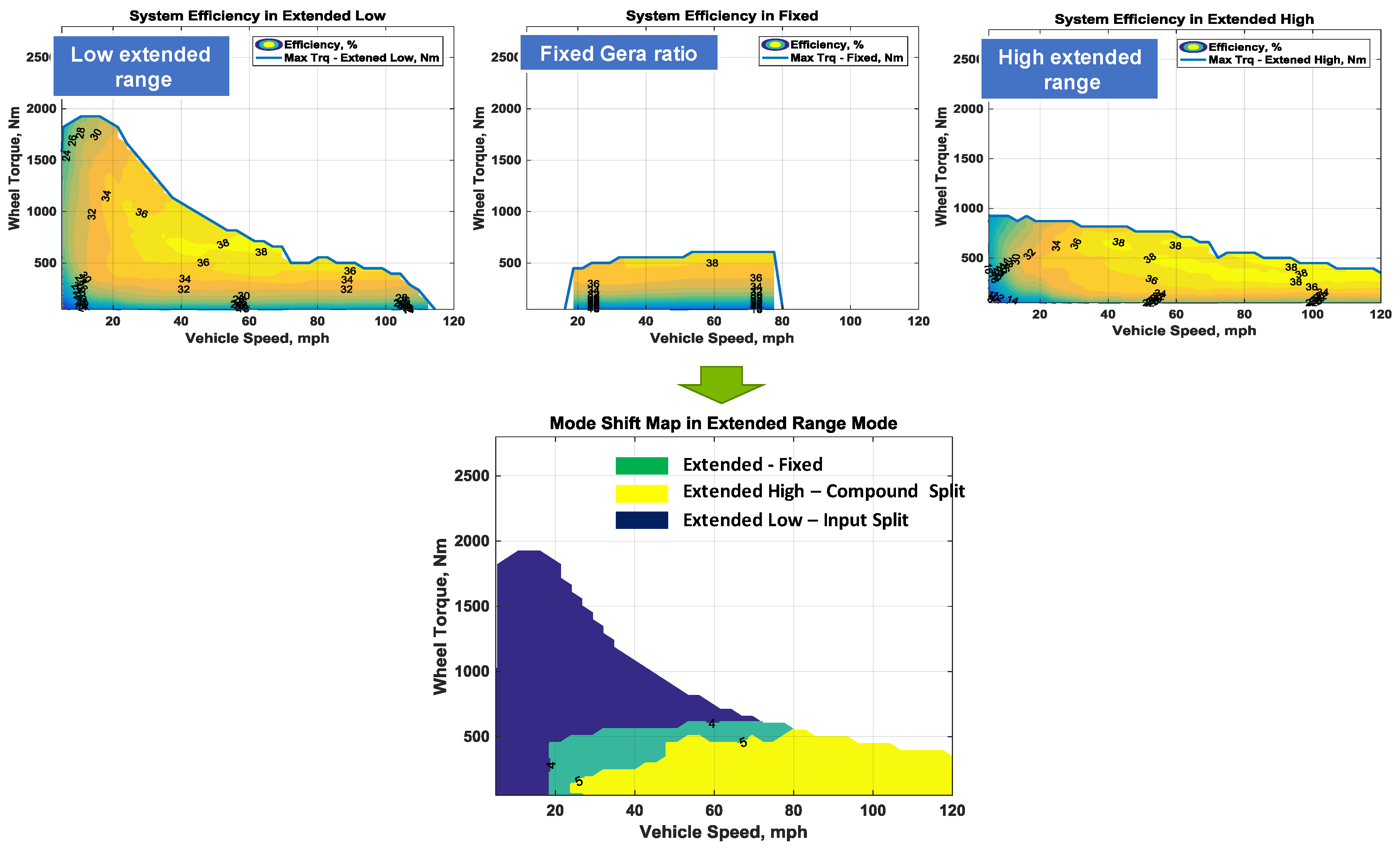
During extended-range operation, the best engine operation minimizing fuel consumption can be determined with the transmission efficiency introduced in Section 2.1. It is the optimal trade-off between engine efficiency and transmission efficiency based on engine-only operation. Among the various powertrain operations that produce the required speed and torque at the output, the most efficient one can give the information of the optimal mode selection. Figure 3 depicts the optimal mode selections for various output load conditions. In tractive effort space, the figure shows the regions in which each of the modes is typically utilized. The fixed gear ratio mode supplements the low extended mode and appears in the transition area between the low and high extended modes. Although we neglected the reactive torque control losses and hydraulic actuator losses, the process provides a general insight and can include the detailed power loss models when they are present.
3. Vehicle Testing Analysis
The APRF has conducted more than 40 driving tests on different cycles and under different thermal conditions. The test procedure was designed to consider different operating conditions. The vehicle was located in the thermal chamber, where the ambient temperature of the facility is well controlled by three different conditions—cold ambient at −7 °C, normal ambient at 21 °C, and hot ambient at 35 °C. However, in this paper, we first focus on analyzing vehicle operation in normal conditions—warmed-up vehicle; 21 °C ambient temperature; and heating, ventilation, and air-conditioning (HVAC) not used. Therefore, all our analysis figures are the result of test data under normal ambient temperature.
To understand the supervisory control concept, we introduce four main analysis results—engine on/off control, transmission mode control strategy, state of charge (SOC) balancing control, and detailed component control concepts. The engine on/off determines the operation mode, and the SOC balancing determines the power management between the engine power and the battery power. The component control, finally, shows how the powertrain components are controlled in detail.
3.1. Engine On/Off Control
The Volt is an EV with extended range, which can operate with full vehicle performance on battery power alone, without using its engine, so long as the battery pack has energy available; this is called the charge-depleting (CD) mode. After the battery SOC decreases to a certain point, the engine is turned on more often and the battery SOC is maintained within a narrow range; this is the charge-sustaining (CS) mode. Figure 4 shows the points when the vehicle driving mode changes from CD to CS mode under normal ambient temperature from the test data for the first- and second-generation Voltec systems. In the first-generation Voltec, engine operation does not occur until the battery SOC drops below 23%. However, in the case of the second-generation Voltec, the vehicle is driven in CD mode down to 18% of battery SOC. Not only has the battery pack energy in the second-generation pack increased by 12% [6], but the operating range of battery SOC has also been expanded.
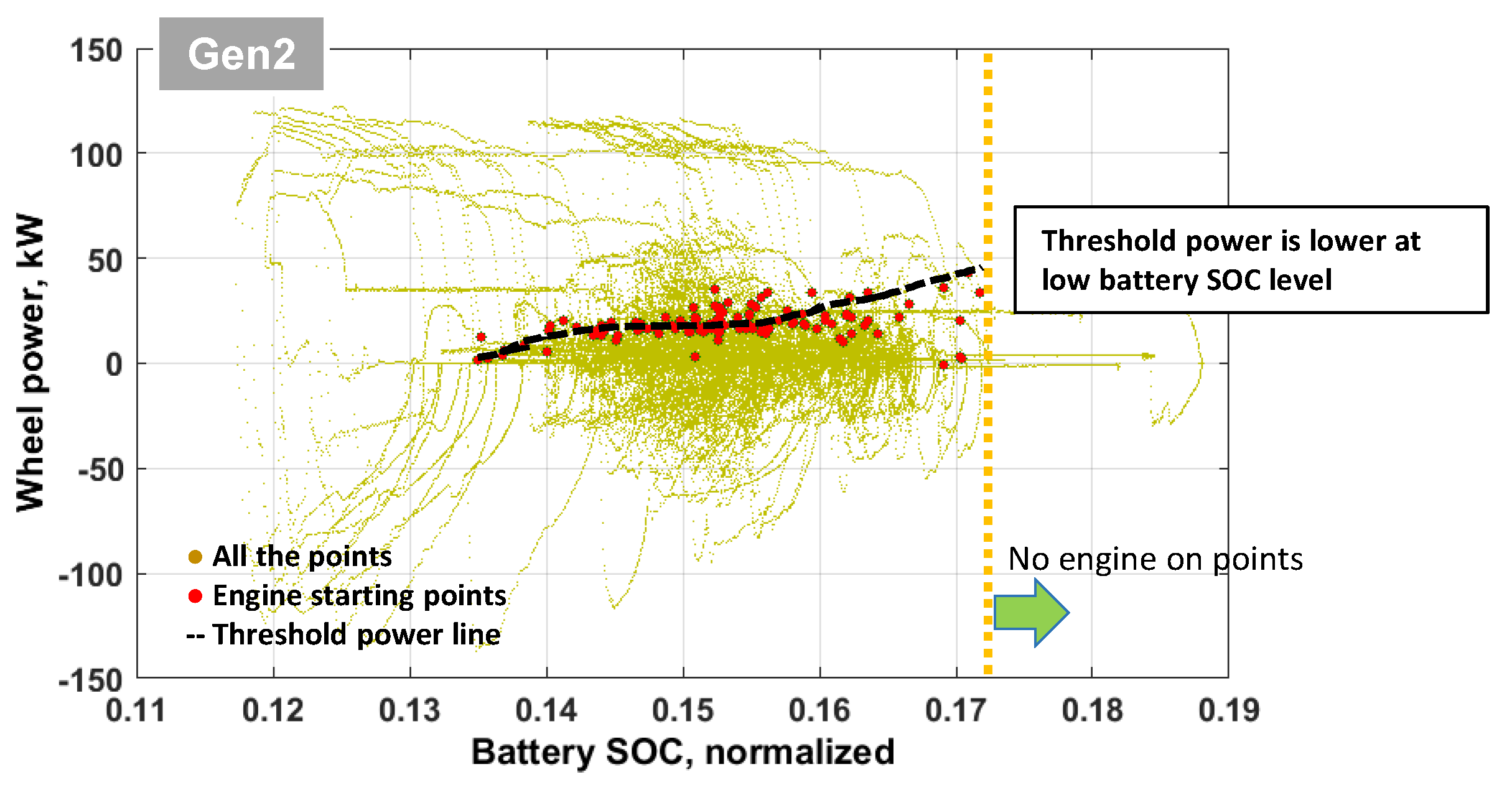
To determine the engine turning-on points for the second-generation Voltec, we plotted the filtered points in the same domain shown in Figure 5. In the figure, we only show the engine starting points when the engine coolant temperature is above 70 °C; it is assumed that the points are obtained under normal operating conditions. In general, we can conclude that the engine-on threshold power is a function of battery SOC. The results show that the engine is turned on early if the SOC is too low, in order to preserve the battery SOC.
On the other hand, it is not easy to determine the engine power threshold for the engine-off condition because the requested power is rapidly reduced when the driver suddenly takes their foot off the pedal. In Figure 6, the wheel power for the engine-off condition does show a trend; the figure shows that the engine is always turned off when the wheel power is negative. The condition that determines whether the engine is completely shut off or fuel cutoff is the vehicle speed, as shown in Figure 6. The engine is not turned off, but instead, stays on idle speed with no fuel if the vehicle speed is higher than about 40 mph. The fuel cutoff occurs mostly in the fixed gear ratio and high extended modes. If the engine speed is not sustained in the idle speed, the electric machine operates at too high a speed to turn on the engine properly. Although the system consumes additional energy because of the friction torque of the engine, this control helps the engine become ready to be turned on rapidly during highway driving.
3.2. Driving Mode Control
The second-generation Voltec provides five driving modes, including two EV operations and three extended-range operations. In EV operations, the transitions from the EV1 mode to EV2 mode are easier compared to the previous system, as the clutch engagement or disengagement is not required. Figure 7a shows that the EV2 mode is used to start the vehicle and the EV2 mode is selected when Electric machine 1 reaches its maximum torque in EV1 mode, to cover the short demand of wheel torque by using both electric machines.
Figure 7 shows that the fixed gear ratio mode supplements the low extended mode when the vehicle speed is over 30 mph. As assessed the system efficiency in Section 2.2, the fixed gear ratio mode appears in the transition area between the low and high extended modes. The high extended mode is used when vehicle speed is over about 40 mph at light loads. However, at higher loads and high speed, the mechanical/electric energy conversion losses in the high extended mode can be reduced by selecting the parallel drive mode.
The driving mode selection rule is also defined in a different domain as shown in Figure 6 (right). The fixed gear ratio mode (blue line) is used if the speed ratio is around 1.53, which means that the system is changing from low extended mode to fixed gear ratio mode to avoid low system efficiency. In a low-speed ratio (<1.53) or high vehicle speed range, the compound power-split mode can be selected since the compound mode has a relatively higher efficiency at around the second mechanical point (MP2), as shown in Figure 1b.
3.3. Power Management Control
When it comes to the supervisory control, the driving mode decision strategy discussed in Section 3.2 is an important control concept. In addition to the mode control, one other important control concept is to split the torque between the two electric machines in EV2 mode or split the power between the mechanical power source and the electrical power source when the engine is turned on. In this section, the control strategies for power management are analyzed for each operation mode.
3.3.1. Torque Distribution in EV2 Operation
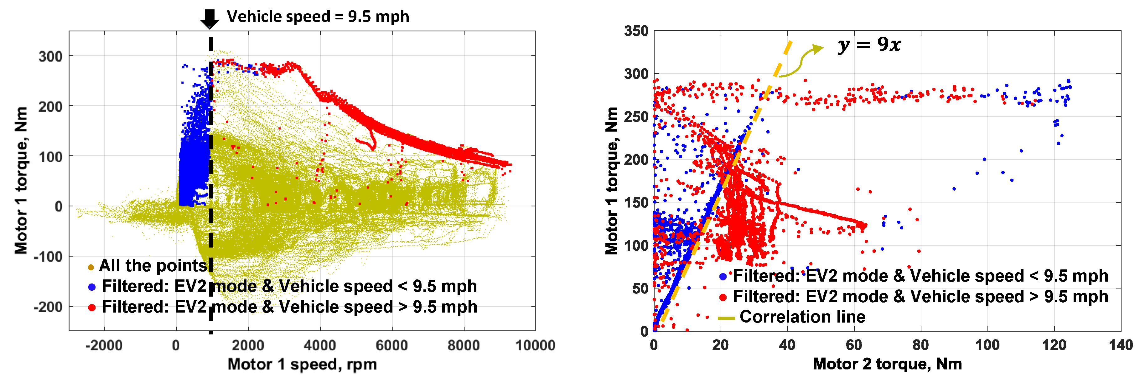
As mentioned earlier, the system can operate in either EV1 or EV2 modes depending on the level of torque demand. When operating the EV1 drive, Electric machine 1 alone is capable of producing torque because it is sized to cover the typical driving conditions. When operating the EV2 drive, the most efficient combination of motor input torque can be selected to meet the output speed and torque, since the powertrain has two degrees of freedom in EV2 mode. Figure 8 shows that there is a boundary of vehicle speed at around 9.5 mph for torque distribution in EV2 mode. When the vehicle speed is lower than 9.5 mph, Electric machine 2 provides only about 10% of demand torque, and Electric machine 1 produces the rest of demand torque in Figure 8 (right). When the vehicle speed is higher than 9.5 mph, Electric machine 1 provides an almost maximum torque that can be generated at that speed, and Electric machine 2 covers the short demand torque to propel the vehicle.
3.3.2. Power Management in Low Extended Mode
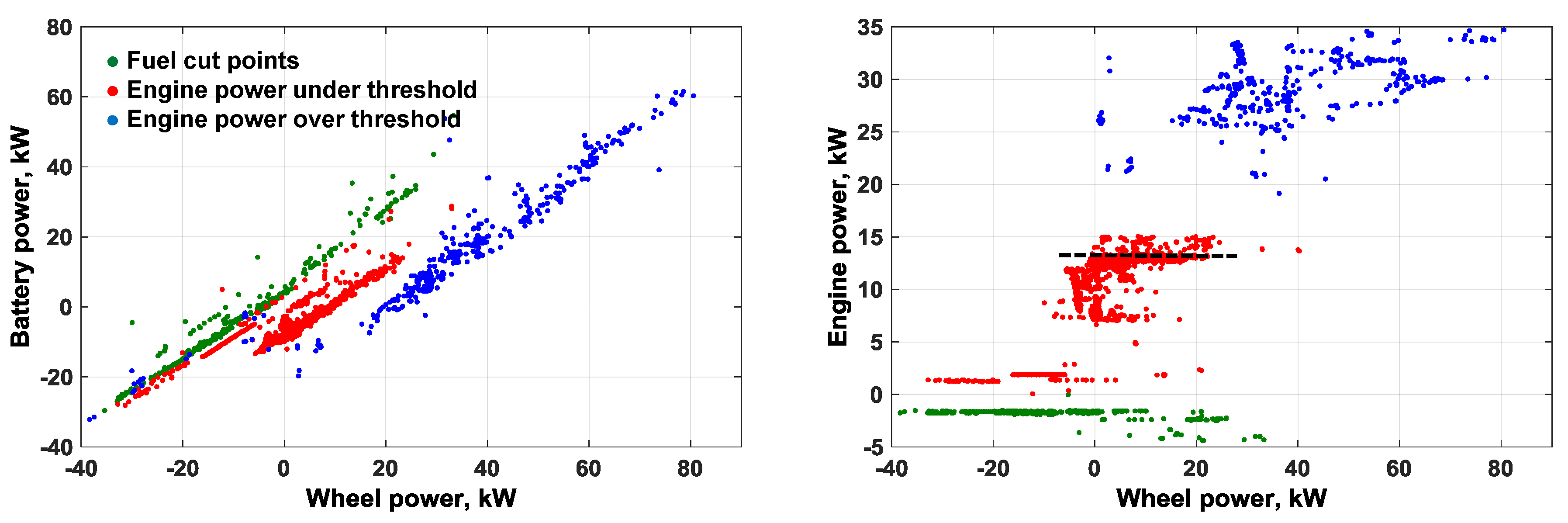
Once the vehicle operation mode, including engine and clutch/brake conditions is specified, one other important control concept is to split the power between the mechanical power source and the electrical power source when the engine is turned on. In the MY 2016 Volt, the main idea of the energy management strategy is that the operation points of the engine are supposed to be controlled in an appropriate range. While the power threshold for the engine starting is a function of SOC, the engine produces surplus power if the wheel power demand is below a certain point. Figure 9 shows filtered operating points when the engine is turned on in low extended mode. In order to obtain the filtered points, we only selected the points when the engine is turned on and is hot enough, and the accelerating demand is not too high. The figure shows a clear trend and indicates that the engine operation is controlled at its best efficiency range, rather than using a wide range. If the required driving power is lower than about 15 kW, the engine operates on its best efficient area and keeps the power level steady. When the required driving power is more than about 15 kW, the engine power increases slightly as the wheel power increases within a narrow range.
3.3.3. Power Management in Fixed Gear Ratio Mode
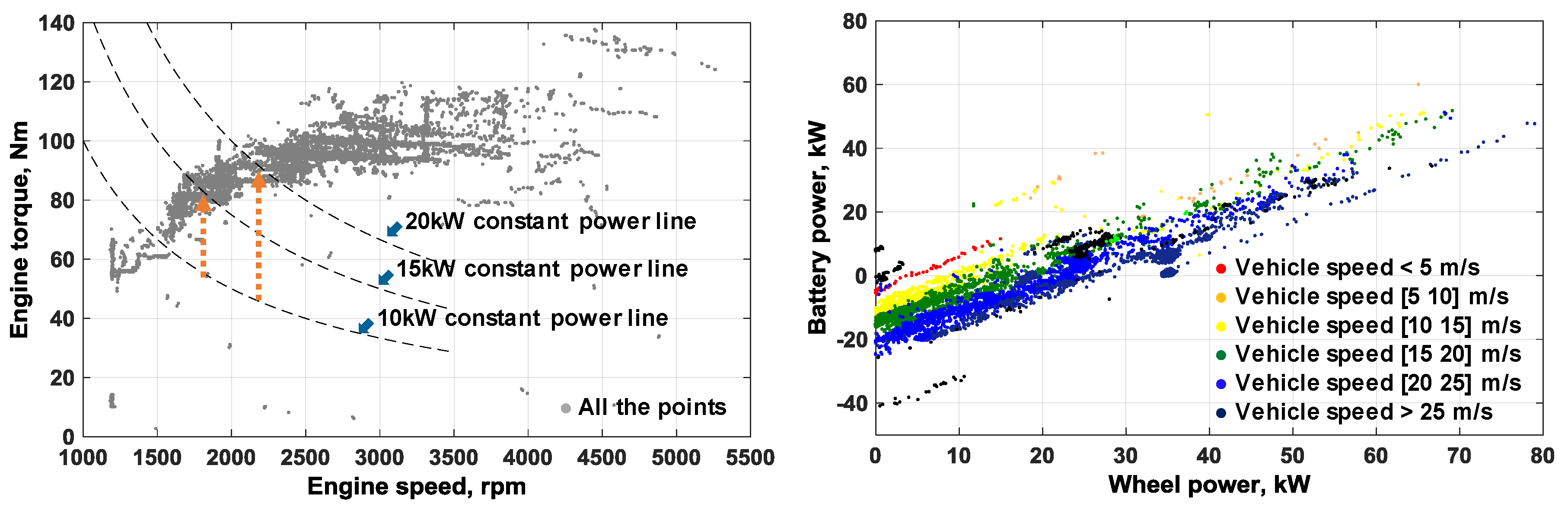
In fixed gear ratio mode, the engine speed is uniquely fixed if the vehicle speed is determined, since the engine is physically connected to the wheels via fixed reduction gear. The relationship between engine speed and torque during operation in parallel mode is shown as grey points in Figure 10 (left). Although, in fixed gear ratio mode, the engine cannot always be operated on its optimal operating torque target line, the engine load adjustment by charging or discharging the high-voltage battery is performed in this mode to fix engine operating points in a highly efficient area. Figure 10 (right) shows that the battery power is proportional to the wheel power but has different gains according to vehicle speed, which means that the higher the vehicle or engine speed, the greater the amount of battery charging at light loads to trace the optimal target speed of the engine.
3.3.4. Power Management in High Extended Mode
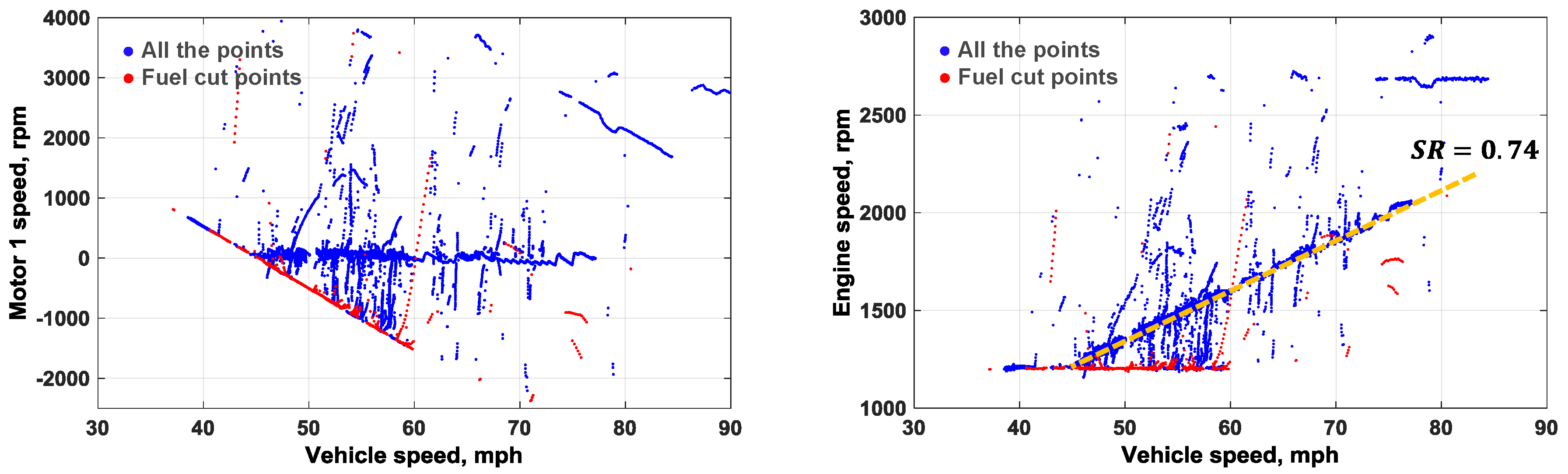
In high extended mode, there is no restriction regarding the rotational speed of the vehicle and the engine as in low extended mode, since they have no physical connection with each other. Therefore, engine speed can be determined arbitrarily without any relationship with vehicle speed. However, Figure 11 shows that Electric machine 1 operates around zero speed to keep the system on the second mechanical points (at speed ratio = 0.74) in high extended mode. When the speed ratio is 0.74, the electromechanical power ratio becomes zero, as shown in Figure 1b, and all the power can be transmitted through the mechanical part to avoid energy conversion losses.
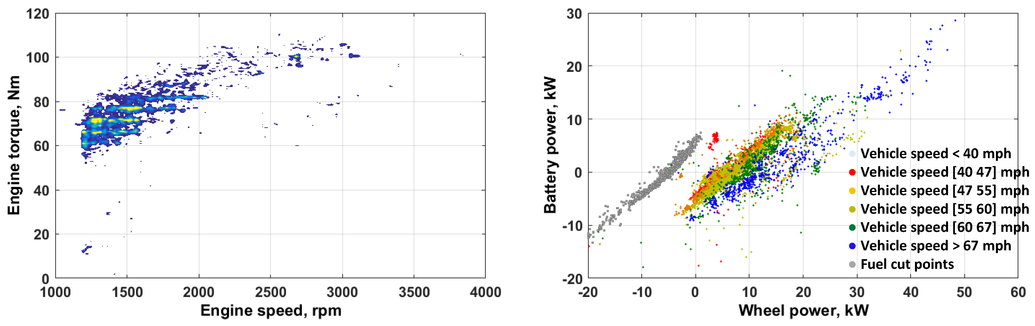
Figure 12 (left) shows the relationship between engine speed and torque during operation in high extended mode. Although, in high extended mode, the engine can be controlled on its optimal operating torque target line, the engine operating points are spread somewhat similar to the parallel mode. As mentioned above, the engine speed is controlled to keep the speed ratio of 0.74 of the second mechanical point, and the system operates at around fixed gear ratio like the parallel mode. Therefore, the engine load should be increased or decreased by charging or discharging the high-voltage battery in order to move the engine operating point toward the higher efficiency point. Figure 12 (right) shows that the battery power is proportional to the wheel power with different gains according to vehicle speed, which is very similar to the power management strategy of the fixed gear mode. As the vehicle speed increases, the engine operating point is adjusted by controlling the amount of battery charging or discharging to maximize fuel efficiency.
4. Conclusions
Information has been provided to aid in understanding the control behaviors of the MY 2016 Volt. In addition to the supervisory control concept, we have presented an assessment of the improvement of the new powertrain system by comparing system efficiency with the previous system. Although a number of sophisticated control concepts were necessarily added to the supervisory control concepts, the main control flow of the vehicle based on test data can be summarized as shown in Supplementary.
First, the engine on/off control is determined by the rule explained in Section 3.1. During EV driving, the use of two electric machines allows for two EV driving modes to provide maximum output torque or increased efficiency by torque distribution. If the engine is on after most of the battery energy has been depleted by EV driving, the operational state of the clutch or brakes is defined to select the extended-range mode. Energy management between the engine and the battery is controlled depending on the powertrain operation mode. Once the operation mode is chosen, the battery power demand is determined by the proportional control power, which also determines the engine power demand by subtracting the battery power demand from the driver power demand. Finally, each component operates according to an optimal target based on engine target and battery power demand.
Although the analysis of the control strategy, especially the energy management of the vehicle, was conducted under normal temperature conditions, this study provides the overall control behaviors of the second generation of the Volt powertrain system. Thus future researchers can use the concepts as a basis for control concept.
5. Future Work
Vehicle components, such as the engine, battery, electric machine, wheel or tire, are affected by temperature. The impact of component temperature on their efficiency will be analyzed. Thermal conditions affect not only the efficiency of components, but also vehicle control. The control strategy and the performance will also be analyzed under various thermal conditions such as cold or hot ambient temperature and soaked or warmed-up vehicle.
The vehicle model and controller will be redesigned in Autonomie to mimic the control behavior when temperatures of components are cold or hot, and the performance degradation of the components will be applied to the mathematical models based on the analysis. Finally, we will integrate the redesigned supervisory controller into a vehicle system, and the vehicle model will be validated with the test data.
Supplementary Materials
The following are available online at https://www.mdpi.com/2032-6653/9/2/29/s1, Summary of control analysis.
Author Contributions
Conceptualization, N.K. and J.J.; Vehicle Testing, K.S.; Analysis, S.C., J.J. and N.K.; Writing-Original Draft Preparation, S.C.; Writing-Review & Editing, N.K.; Project Administration, R.V. and A.R.
Funding
This work was supported by the U.S. Department of Energy’s Vehicle Technologies Office under the direction of Mr. David Anderson. The submitted manuscript has been created by UChicago Argonne, LLC, Operator of Argonne National Laboratory (“Argonne”). Argonne, a U.S. Department of Energy Office of Science laboratory, is operated under Contract No. DE-AC02-06CH11357. The U.S. Government retains for itself, and others acting on its behalf, a paid-up nonexclusive, irrevocable worldwide license in said article to reproduce, prepare derivative works, distribute copies to the public, and perform publicly and display publicly, by or on behalf of the Government.
Conflicts of Interest
The authors declare no conflicts of interest.
Abbreviations
| APRF | Argonne’s Advanced Powertrain Research Facility |
| BK | brake |
| CD | charge depleting |
| CL | clutch |
| CS | charge sustaining |
| DOE | the U.S. Department of Energy |
| EV | electric vehicles |
| EVT | electrically variable transmission |
| FG | fixed gear ratio |
| HVAC | heating, ventilation, and air-conditioning |
| MG | electric machine |
| MP | mechanical point |
| MY | model year |
| OWC | one-way clutch |
| PHEV | plug-in hybrid electric vehicle |
| SOC | state of charge |
| SR | speed ratio |
References
- Kim, N.; Duoba, M.; Kim, N.; Rousseau, A. Validating Volt PHEV Model with Dynamometer Test Data Using Autonomie. SAE Int. J. Passeng. Cars Mech. Syst. 2013, 6, 985–992. [Google Scholar] [CrossRef]
- Kim, N.; Jeong, J.; Rousseau, A.; Lohse-Busch, H. Control Analysis and Thermal Model Development for Plug-In Hybrid Electric Vehicles. SAE Int. J. Altern. Powertrains 2015, 4, 260–268. [Google Scholar] [CrossRef]
- Jeong, J.; Karbowski, D.; Rousseau, A.; Rask, E. Model Validation of the Honda Accord Plug-In. In Proceedings of the SAE 2016 World Congress and Exhibition, Detroit, MI, USA, 12–14 April 2016. SAE Technical Paper 2016-01-1151. [Google Scholar] [CrossRef]
- Jeong, J.; Lee, W.; Kim, N.; Stutenberg, K.; Rousseau, A. Control Analysis and Model Validation for BMW i3 Range Extender. In Proceedings of the WCX™ 17: SAE World Congress Experience, Detroit, MI, USA, 4–6 April 2017. SAE Technical Paper 2017-01-1152. [Google Scholar] [CrossRef]
- Lohse-Busch, H.; Duoba, M.; Rask, E.; Stutenberg, K.; Gowri, V.; Slezak, L.; Anderson, D. Ambient Temperature (20°F, 72°F and 95°F) Impact on Fuel and Energy Consumption for Several Conventional Vehicles, Hybrid and Plug-In Hybrid Electric Vehicles and Battery Electric Vehicle. In Proceedings of the SAE 2013 World Congress & Exhibition, Detroit, MI, USA, 16–18 April 2016. SAE Tech. Pap. 2013-01-1462. [Google Scholar] [CrossRef]
- The Downloadable Dynamometer Database (D3) Offers Publicly available Testing Data Regarding Advanced Technology Vehicles. Available online: http://www.anl.gov/energy-systems/group/downloadable-dynamometer-database (accessed on 3 May 2018).
- Conlon, B.; Blohm, T.; Harpster, M.; Holmes, A.; Palardy, M.; Tarnowsky, S.; Zhou, L. The Next Generation “Voltec” Extended Range EV Propulsion System. SAE Int. J. Altern. Powertrains 2015, 4, 248–259. [Google Scholar] [CrossRef]
- Argonne National Laboratory. Autonomie. 2017. Available online: http://www.autonomie.net (accessed on 3 May 2018).
- Kim, N.; Kwon, J.; Rousseua, A. Trade-off between Multi-mode Powertrain Complexity and Fuel Consumption. In Proceedings of the 25th World Battery, Hybrid and Fuel Cell Electric Vehicle Symposium & Exhibition, Shenzhen, China, 5–9 November 2010. [Google Scholar]
- Jurkovic, S.; Rahman, K.; Patel, N.; Savagian, P. Next Generation Voltec Electric Machines; Design and Optimization for Performance and Rare-Earth Mitigation. SAE Int. J. Altern. Powertrains 2015, 4, 336–342. [Google Scholar] [CrossRef]
Figure 1.
Power characteristics.
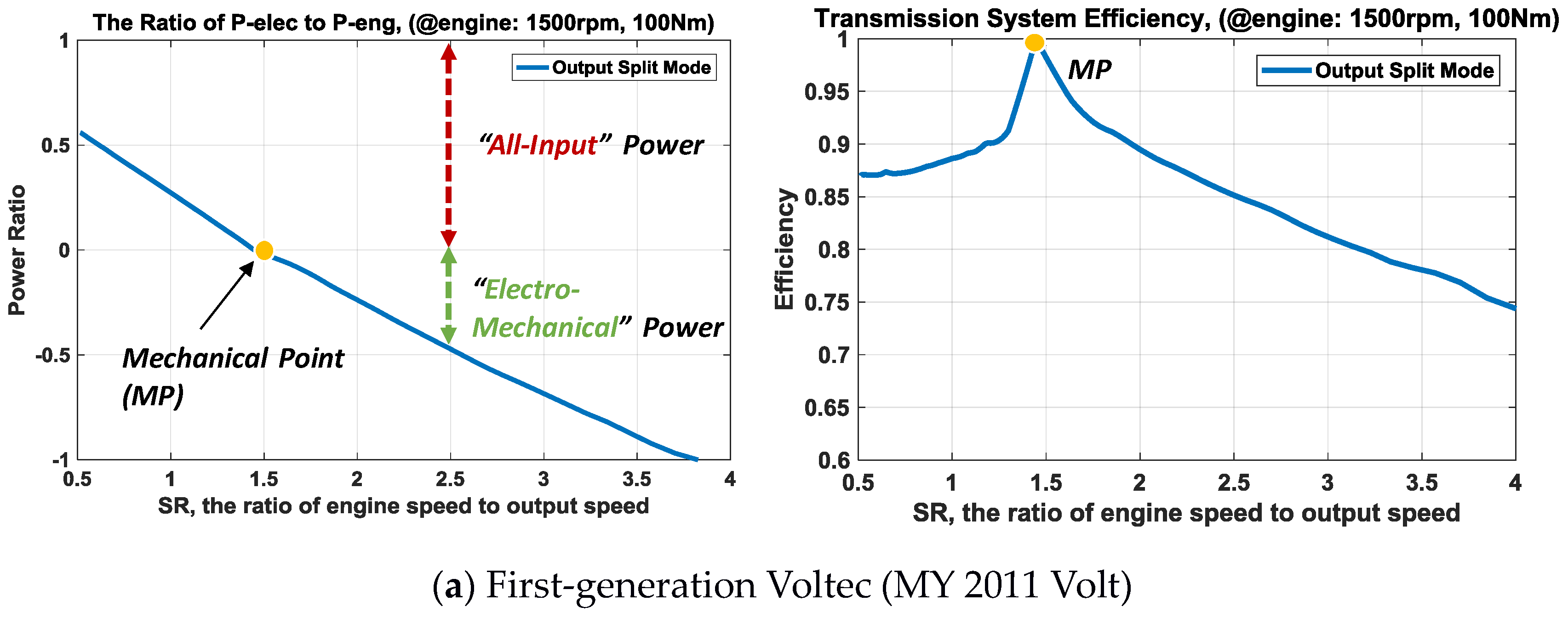

Figure 2.
EV drive efficiency maps and mode selection during EV operation.

Figure 3.
Mode shift map for engine-only operation.

Figure 4.
Wheel power according to battery SOC with or without the engine on.
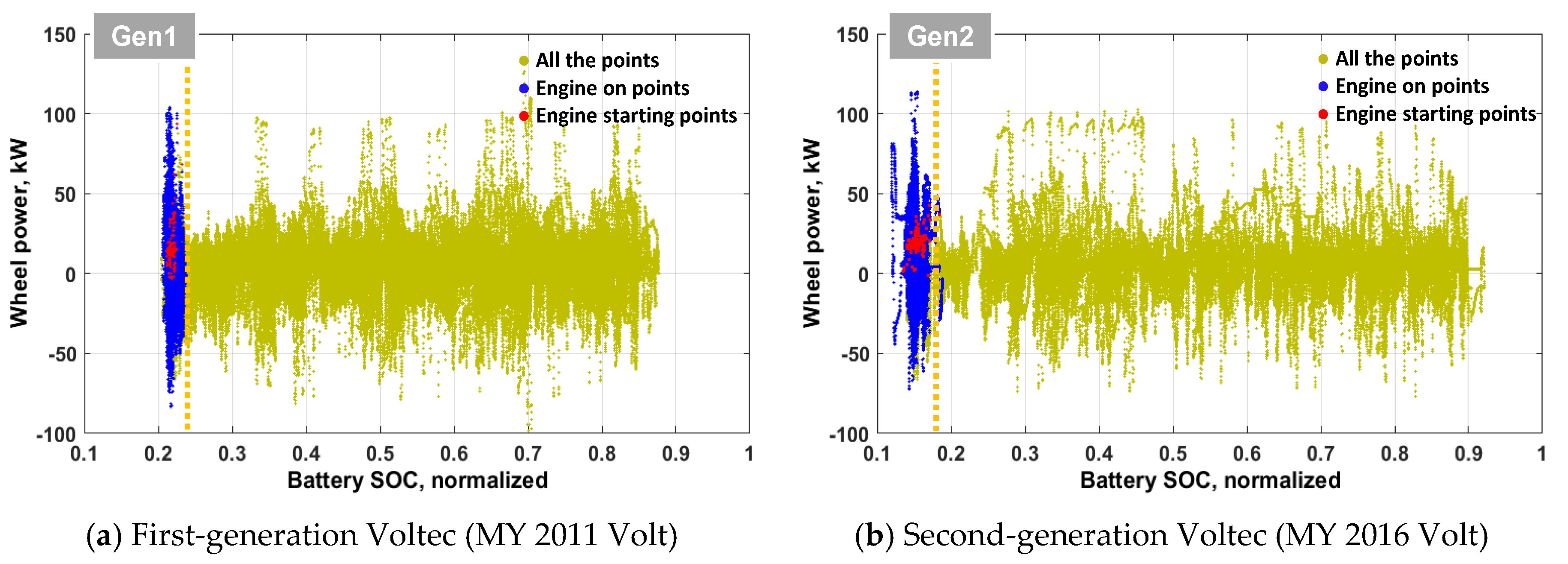
Figure 5.
Wheel power according to battery SOC when the engine is turned on.

Figure 6.
Wheel power and engine speed according to vehicle speed when the engine is turned off.

Figure 7.
Wheel torque according to vehicle speed for each driving mode.
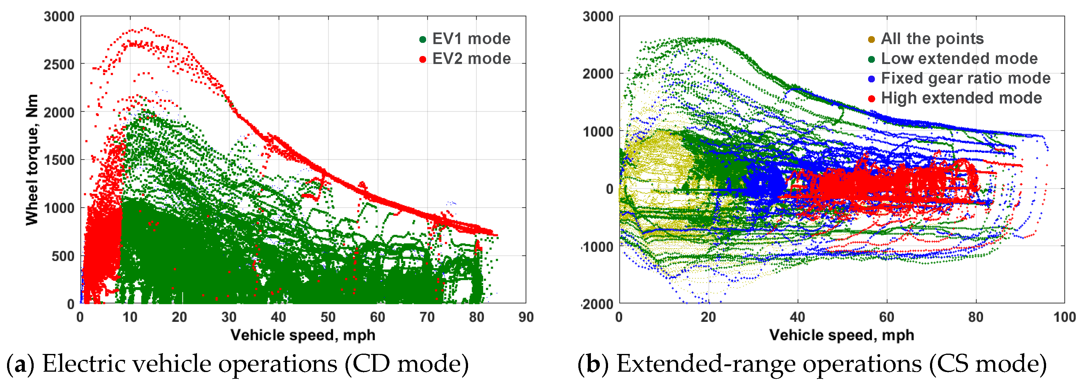
Figure 8.
Torque distribution in EV2 operation mode.

Figure 9.
Battery power and engine power according to wheel power in low extended mode.

Figure 10.
Engine operating points and battery power according to wheel power in fixed gear ratio mode.
Figure 10.
Engine operating points and battery power according to wheel power in fixed gear ratio mode.

Figure 11.
Electric machine 1 speed and engine speed according to vehicle speed in high extended mode.
Figure 11.
Electric machine 1 speed and engine speed according to vehicle speed in high extended mode.

Figure 12.
Engine operating points and battery power according to wheel power in high extended mode.
Figure 12.
Engine operating points and battery power according to wheel power in high extended mode.


Table 1.
Differences between MY 2011 Volt and MY 2016 Volt.
| MY 2011 | MY 2016 | |
|---|---|---|
| Configuration (system operation mode) |  |  |
| Engine | 1.4 L, 63 kW | 1.5 L, 75 kW |
| Battery | Li-Ion, 16.5 kWh, 110 kW | Li-Ion, 18.4 kWh, 120 kW |
| Motor1(MG1) | 111 kW | 87 kW |
| Motor2(MG2) | 55 kW | 48 kW |
| PGs ratio | 3.24 | 2.87, 3.08 |
| Final drive | 2.16 | 2.64 |
© 2018 by the authors. Licensee MDPI, Basel, Switzerland. This article is an open access article distributed under the terms and conditions of the Creative Commons Attribution (CC BY) license (http://creativecommons.org/licenses/by/4.0/).
Share and Cite
MDPI and ACS Style
Kim, N.; Choi, S.; Jeong, J.; Vijayagopal, R.; Stutenberg, K.; Rousseau, A. Vehicle Level Control Analysis for Voltec Powertrain. World Electr. Veh. J. 2018, 9, 29. https://doi.org/10.3390/wevj9020029
AMA Style
Kim N, Choi S, Jeong J, Vijayagopal R, Stutenberg K, Rousseau A. Vehicle Level Control Analysis for Voltec Powertrain. World Electric Vehicle Journal. 2018; 9(2):29. https://doi.org/10.3390/wevj9020029
Chicago/Turabian StyleKim, Namdoo, Sungwook Choi, Jongryeol Jeong, Ram Vijayagopal, Kevin Stutenberg, and Aymeric Rousseau. 2018. "Vehicle Level Control Analysis for Voltec Powertrain" World Electric Vehicle Journal 9, no. 2: 29. https://doi.org/10.3390/wevj9020029