Dimensioning and Optimization of Hybrid Li-Ion Battery Systems for EVs


1
Institute for Power Electronics and Electrical Drives (ISEA), RWTH Aachen University, Jaegerstr. 17/19, 52066 Aachen, Germany
2
Juelich Aachen Research Alliance, JARA-Energy, 52425 Juelich, Germany
3
Institute for Power Generation and Storage Systems (PGS), E.ON Energy Research Center, RWTH Aachen University, Mathieustr. 10, 52074 Aachen, Germany
*
Author to whom correspondence should be addressed.
World Electr. Veh. J. 2018, 9(2), 19; https://doi.org/10.3390/wevj9020019
Submission received: 31 May 2018
/
Revised: 24 June 2018
/
Accepted: 25 June 2018
/
Published: 28 June 2018
(This article belongs to the Special Issue Selected Papers from The 30th International Electric Vehicles Symposium and Exhibition (Stuttgart, Germany))
Abstract
:Commercial electric vehicles nowadays are powered by a battery system containing one kind of lithium-ion battery cell. Due to the fixed ratio of the cells’ maximum power to nominal energy, the possibilities for designing power and energy of the battery pack independently are limited. The battery system’s energy and maximum power can only be scaled by adapting the number of cells and modules, and the parameters furthermore depend on the characteristics of the cells used. Additional power electronics in the form of one or more dc/dc converters can be used to form a hybrid battery system comprised of more than one pack and different cell technologies. This allows for individually designing each battery pack and thus optimizing the overall battery system specification. This work presents a battery dimensioning and optimization approach for single pack and hybrid battery systems. It is based on an evolutionary optimization algorithm and a detailed, modular Matlab-Simulink vehicle model. Studies on the advantages of hybrid batteries for different vehicle classes were carried out. Results indicate that optimized hybrid battery systems can lead to weight and volume savings and further advantages in total cost of ownership, for example, by enhanced battery life time or reduced investment costs. On the other hand, they require more complex control logic, which is also discussed in this paper.
1. Introduction
Electric vehicles (EVs) still suffer from slow market penetration in Germany and worldwide, although German politics have sought for a quick ramp-up since 2011 [1] and are currently supporting purchases of new EVs with a monetary reward. The main hurdles still in place are the lower mobility flexibility when using EVs due to their limited range compared to combustion driven vehicles, as well as their higher investment costs—at least, if not significantly funded. One of the main cost drivers of EVs is the battery system, although cell prices have decreased over the last years [2]. A sophisticated dimensioning and design of the battery system is thus essential for the successful electrification of vehicles. Otherwise, battery systems may be dimensioned conservatively in terms of initial energy to guarantee a certain range at the end of life. This may lead to systems outside the economical and ecological optimum.
This work presents an approach to address the above-mentioned challenges in the design and dimensioning process of vehicle traction battery systems. The key idea is to equip electric vehicles with a hybrid battery system consisting of different battery cell types instead of using only one type of cell. The background leading to this approach is explained in the following.
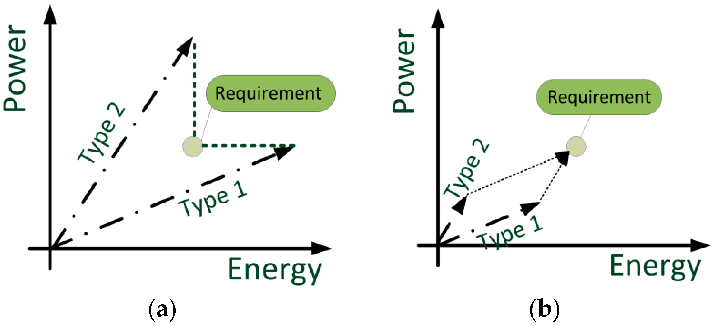
A typical battery cell used in current EVs is neither a cell designed towards very high energy (apart from Panasonic cells used by Tesla), nor is the cell designed for high power as in the case for hybrid electric vehicles. It is not possible to increase the energy density while maintaining the power density of the cell. Typically, higher energy densities of battery cells are gained by increasing the thickness of the active material layers or by reducing the thickness of copper and aluminum sheets. Both measures decrease the power capability of the cell. Further measures on material level usually also lead to disadvantages in terms of power capability or other characteristics—e.g., cycle life time of the cell. Thus, a typical automotive battery cell is designed as a trade-off between enabling driving agility through maximum electrical power of the battery and range of the vehicle, influenced by the battery’s energy content. This leads to an over-dimensioning of the battery system if the available cell types do not reflect the desired power-to-energy ratio, which is schematically shown in Figure 1a.
The battery system’s energy and power can be linearly scaled following the arrow of battery cell type 1 using additional cells (e.g., connecting more cells in parallel). Note that this is a simplification, since the number of battery cells cannot be freely modified by one cell. Instead, one has to respect the allowed voltage range when connecting additional cells serially, and that the number of cells is doubled when connecting an additional cell in parallel. These boundary conditions increase the complexity when dimensioning battery systems. In the case shown in Figure 1a, the usage of battery type 1 leads to an over-dimensioning in terms of energy to meet the power requirements. On the other hand, the shown battery type 2, with a higher power-to-energy ratio than type 1, leads to significantly more power than required to meet the energy demand. Note that in most of the commercial battery systems on the market, a battery manufacturer would use type 1, since additional energy in the battery system translates to additional range or longer lifetime with reduced stress on each cell. However, this is not the cost-optimal solution, as the battery is larger than required.
In contrast to this single-pack approach, a hybrid battery system using two different cell types enables an exact dimensioning of both power and energy, as shown in Figure 1b. Here, a certain part of the required energy is provided by using the respective number of cells of type 1. In the simplified case in Figure 1b, the number can be determined by parallel shifting of the arrow of cell type 2 until the combination of both arrows exactly matches the requirement, i.e., when forming a parallelogram. The number of required cells of type 2 is then simply determined by the length of the type 2 arrow. As mentioned before, in reality, one has to respect the boundary conditions of adding and subtracting cells and still maintaining the allowed string voltage range. However, in many cases, this hybrid battery approach leads to lower mass, volume, and costs of the complete system, as discussed in the analysis of this work.
Current battery systems in EVs are well suited for one type of EV, but it is difficult to scale them to different vehicle classes and models like it is done with sizing of combustion engines for more powerful models. Hybrid battery systems, on the other hand, can be dimensioned rather freely in terms of energy and power. An OEM (original equipment manufacturer) might therefore use modules of a high-energy (HE) pack across his models’ portfolio and add further high-power (HP) modules for more powerful vehicle models and classes. Such an approach supports the economy of scales effect and thus may contribute to decreasing EV investment costs.
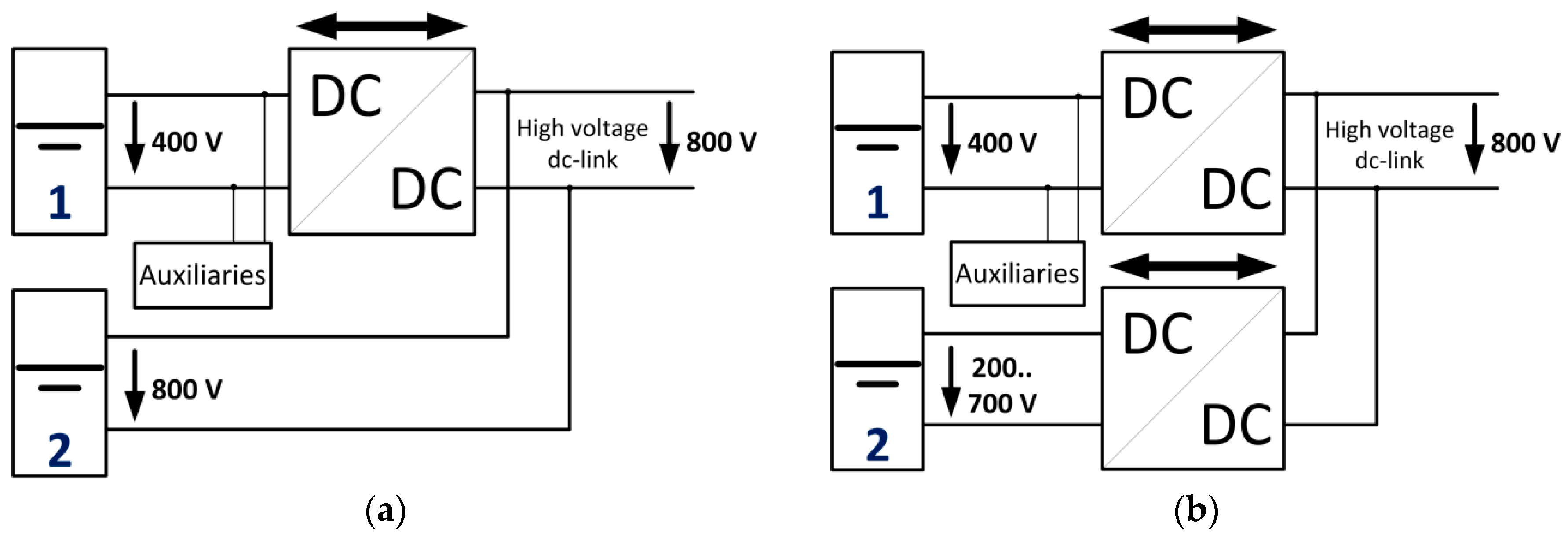
Hybrid battery systems require additional power electronics to adapt the different cell characteristics—e.g., pack voltage levels and voltage curves. In the easiest case, this can be one dc/dc converter attached to the clamps of one pack, as shown in Figure 2a.
Such a system topology enables the use of different voltage levels in the drivetrain simultaneously, e.g., using 800 V traction inverters (not shown in the figure) for high-power drives and one battery pack at 400 V nominal voltage and a second one at either 800 V dc-link voltage (Figure 2a) or a completely different voltage (Figure 2b). A dc-link voltage of 800 V has the advantage that the charging power can be fed into the car with lower current than with 400 V system voltage, and thus allows higher power with the same cable diameter [3]. The topology shown in Figure 2b allows dimensioning both packs completely independently in terms of used cell types, as well as number of serially connected cells. The resulting pack voltages are translated to one dc-link voltage by the two dc/dc converters. Furthermore, decoupling both battery packs from the dc link (and thus the traction inverter(s)) may bring additional advantages in terms of efficiency, since the dc-link voltage can be controlled, dependent on the speed, as discussed in [4]. Due to these reasons, the topology shown in Figure 2b was used in the methodology and analyses described in this work.
Hybrid battery systems have been analyzed in literature for many applications, from consumer electronics [5] to stationary and mobile applications, using many different types of energy storage technologies. Most of the combinations use supercapacitors to increase the system’s maximum electrical power [6,7,8]. Supercapacitors, however, have a low energy density compared to lithium-ion (Li-ion) batteries and a very high cyclic stability in combination with a very high power capability. The latter properties are not required in the application of hybrid battery systems for full electric vehicles. Furthermore, the voltage of capacitors is linearly dependent on the state of charge and thus requires a wider operating range of the connected power electronics (e.g., inverter) compared to a battery with a rather flat state-of-charge-voltage curve. This work consequently focuses on the combination of different types of Li-ion batteries in one EV. Li-ion batteries cover a wide field of energy-to-power ratios. One distinguishes between high-power cells and high-energy cells. High-power cells are used in applications focusing more on power than on range or run time. Today, they typically consist of lithium titanate oxide anodes (LTO) in combination with a nickel manganese cobalt oxide (NMC) cathode, or lithium iron phosphate cathodes (LFP) in combination with a graphite anode. High-energy cells, on the other hand, consist of silicon-doped graphite anodes and transition metal cathodes, like in Tesla’s battery packs or in consumer products. As mentioned before, the amount of active material is higher in high-energy cells, with the disadvantage of lower power capability.
The dimensioning process for hybrid battery systems is even more difficult than it is for single-pack battery systems, as described in Section 2.3. Due to the complex solution space, the optimization process cannot be performed manually. Optimization goals can be chosen amongst or be a combination of cost minimization, weight and volume reduction, or minimization of environmental impact. The optimization methodology and results for specific vehicle types are presented in the next sections.
2. Description of the Battery Optimization Methodology
The overall goal of the methodology is to find well-suited battery system solutions for defined vehicle requirements, such as speed, range, acceleration, load capacity, and life time. This requires evaluating how a certain battery system covers these requirements when used in the vehicle. The requirements of the car are thus not translated to battery requirements, which are very complex in some cases, since there is a circular dependency of battery parameters and vehicle requirements: The weight of the battery influences acceleration of the vehicle, which sets the requirement for electrical power of the battery. To analyze and compare different battery systems quantitatively, a detailed vehicle model was created and implemented in Matlab-Simulink in the frame of the research project “HV-ModAL”. It is explained in Section 2.1. The specification and modularization of the battery is enabled by an external scaling possibility and the choice amongst a certain cell portfolio, which is described in Section 2.2. The optimization tool itself is shown schematically in Figure 3 in the right column. It has functional interfaces to the vehicle model to feed in parameter sets—most of all, the specification of the battery systems which are evaluated. The interface is further used to receive the simulation results. The optimization tool itself (left in Figure 3) is implemented in Matlab and makes use of an evolutionary optimization algorithm. This main part of the tool is explained in Section 2.4.
The optimization process is initiated by setting battery parameters, which are then fed into the vehicle model. The vehicle model is then executed in certain driving cycles to analyze the battery’s performance under real-life conditions. The optimization tool receives the results of these scenarios and automatically assesses the battery system currently under investigation. The steps of evaluating the simulation results and feeding new, optimized battery specifications (parameters) into the vehicle model is repeated several (thousand) times, depending on the optimization performance, until a solution is found which fulfills the requirements and a stopping condition of the optimization is reached. The vehicle model, as well as the actual battery optimization tool, are described in the following sections.
2.1. Vehicle Model
The vehicle model is implemented in Matlab-Simulink. It contains submodels of all relevant drivetrain components of an EV (batteries, dc/dc converters, inverters, and machines), as well as a chassis and a driver model.
The chassis model calculates the vehicle speed, resulting from the applied torque of the machine(s). The quantity and type of each component is not static but can be chosen prior to every simulation start within certain boundaries. It is possible to evaluate a vehicle with just one battery, one inverter, and one electrical machine and compare it to a topology with four different machines, four inverters, and five different battery packs with dc/dc converters. The whole model is fed with speed and slope over time profiles, representing logged and standard driving profiles, like WLTP (Worldwide Harmonized Light-Duty Vehicles Test Procedure) [9] or acceleration tests. The requirements for each vehicle type have been determined by the OEMs and Tier 1 suppliers in the consortium and are motivated by current and future electric vehicle perspectives.
2.2. Battery Model
The majority of the battery model is part of the vehicle model. However, some parts of the model do not influence the driving behavior—e.g., the cost or environmental model. The implemented battery model is described in the following.
The chosen battery cells for this exemplary portfolio were characterized on the test benches of the Institute for Power Electronics and Electrical Drives (ISEA) of RWTH Aachen University. Their characteristics are summarized in Table 1.
There are no explicit favors towards any of the cell manufacturers or products. Amongst the cells, all three major cell formats are present: prismatic cells (like in BMW i3), pouch bag cells (like in Smart electric drive [10]), and cylindrical cells (like in Tesla Model S [11]). The portfolio contains very high energy cells as well as very high power cells, as can be seen from the gravimetric energy and power densities. This also motivates the differing anode and cathode combinations ranging from common NMC (nickel manganese cobalt oxide) cathodes to NCA (nickel cobalt aluminum oxide) and LFP on the cathode side and common graphite to silicon-doped graphite and LTO on the anode side. The different cell characteristics significantly influence the cell costs relative to their nominal energy content. These were determined using a bottom-up cost model, based on the “BatPac” approach by Argonne National Laboratory [12,13,14,15] and the Tesla Battery Report [16]. This approach theoretically designs each cell with its specific parameters: the electrodes are defined by their material, the thickness of their active and passive material, and by the length of the electrodes (in the case of cylindrical cells or folded electrodes) or the number of layers (in the case of stacked electrodes). The separator is specified by its thickness, which leads to a certain amount on the cell level, where all anode and cathode layers are separated. Furthermore, there are parameters for the housing material. The material amounts were extracted from measured data from a post-mortem analysis carried out at the institute, as well as from adapted assumptions from the “BatPac” tool. Based on the material amounts and assumptions for producing the cells in high volumes, the individual cell costs have been determined. The electrical parameters are not based on the theoretical model but measured in real experiments and then fed into models. The measurements cover the determination of the voltage-state-of-charge curve and pulse measurements to determine the internal resistance at different temperatures and different states of charge. The results are stored in 3D lookup tables.
The total costs of ownership (TCO) of an EV are significantly influenced by the aging of the battery system. If the aging effect exceeds a certain limit, the battery system has to be over-dimensioned initially to compensate for the decrease in capacity and power capability. Key figures in this context often are 70% remaining capacity after 8 years or 100,000 km [17,18,19]. To evaluate the aging effect of dedicated battery packs in each vehicle, a straightforward battery-aging model was included. The used data was adapted from a battery-aging study and model by Ecker et al. [20] and Schmalstieg et al. [21] and transferred to the cells in this portfolio. The relative aging factors shown in Table 1 do not all reflect measured data, as battery-aging characterization is very time consuming. An aging rate of 1.4 (assumed for the Kokam cell by the South Korean manufacturer Kokam Co., Ltd.) means that the capacity fade after one equivalent full cycle is 1.4 times the capacity decrease after one equivalent full cycle of the reference (SB LiMotive cell in this cell portfolio). LTO anodes are assumed to have a very good cyclic stability, since volumetric expansion and contraction seen in graphite anodes does not occur in this material. Furthermore, these battery cells do not suffer from Li plating [22], which, in addition to posing safety issues, also leads to capacity fade in cells with graphite anodes. Thus, the Toshiba cell’s aging rate is assumed to be 20% of the automotive grade SB LiMotive cell.
The aging model itself analyses the cyclic-aging stress on the batteries through the car usage in the specified aging driving cycles (micro- and macrocycles), as well as the stress through calendric aging. The latter mainly depends on the average voltage and temperature of the battery system. Note that, due to performance reasons of the tool chain, the complete vehicle life of eight years is not simulated. Instead, the aging driving cycles are simulated once for each battery system under investigation to determine the above-mentioned stress factors. Furthermore, it is assumed that both aging factors (cyclic and calendric) can be expressed with a linear behavior in the relevant time frame (eight years and approximately 100,000 km) [23]. Using that extrapolation approach, the capacity decrease and resistance increase can be approximated for the cycle life so that the battery system can also be evaluated at the point in time where the battery has been used for 100,000 km of driving and eight years. The complete aging model was implemented in Matlab with an interface to the Simulink vehicle and battery model to feed in the “aged” battery parameters.
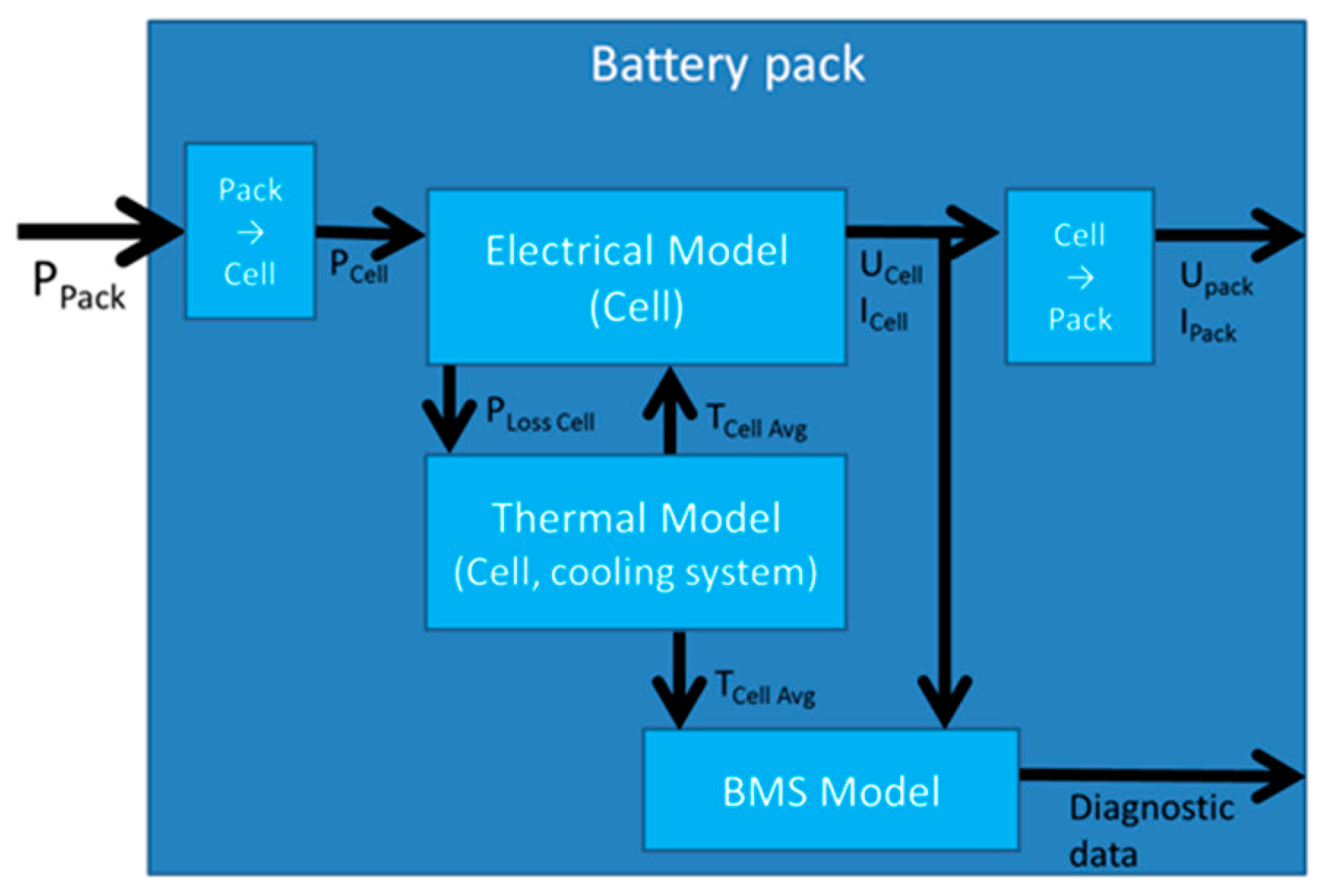
The generic battery model, as part of the Matlab Simulink vehicle model, internally consists of an electrical model interacting with a thermal model and a battery management model. The structure of this “online” model is shown in Figure 4 and explained in the following. Note that the vehicle model has five instances of this library to simulate a maximum number of five completely different battery pack types. An instantaneous power (PPack) is input to each pack at every time step. This is the power extracted from the individual pack or fed back into the pack during recuperation. This power is scaled down to one cell and then further processed in the electrical model. The electrical model consists of an open circuit voltage part, a serial resistor, and an RC element (parallel connection of a resistor and a capacitor), and is parameterized by electrical cell tests at different temperatures, as mentioned above. Differences in cell behavior in one string, which do occur in real battery systems, were neglected in order to maximize computing efficiency. A cell voltage balancing system was thus not modeled. The electrical model calculates the voltage response to a certain power, which is fed into the battery pack, or vice versa. It further computes the thermal loss power according to the electrical power and the measured and modeled internal resistances, which is then fed into the thermal model.
The thermal model can represent a battery pack with pure passive cooling, with active air cooling, or with active liquid cooling. The type of cooling system is chosen before the simulation is started. Each component of the battery system is assumed to have a homogenous temperature distribution within. Temperature gradients inside the system model can thus only exist between components, e.g., between cell and cooling channel or surrounding air. The temperature of the individual components is calculated based on the heat transfers into ( and out of the component (), the component’s initial temperature (, its mass (, and thermal capacity ( according to Equation (1). This leads to an efficient simulation with limited computational errors.
The battery model further consists of a battery management model. Besides other values, it outputs the battery’s state-dependent maximum available power and also controls the cooling system of the pack, depending on the actual temperature and the individual temperature boundary conditions of each cell type.
At least one instance of the above-described combination of electrical-thermal and battery management model has to be available and active in the vehicle model. In the case of hybrid battery systems, there can be up to five instances of battery models, each one parameterized individually prior to simulation. This approach enables the tool chain to automatically find the most suitable combination of cell types and dimension of the individual packs, as described in Section 2.4.
As mentioned above, the tool assumes that in the case of a hybrid battery system, each pack is connected via one suitable dc/dc converter to the dc link. The dc/dc converter was chosen according to the maximum power of the individual pack. The investment costs for the dc/dc converters in the near future were assumed to be 6 $/kW in this work.
2.3. Power Distribution in Hybrid Battery Systems
In the case of just one battery pack, the complete power for the drivetrain and auxiliaries is extracted from this pack. Hybrid battery systems, on the other hand, require a sophisticated power distribution logic, continuously determining which portion of traction power is taken out of which pack, respectively, and fed into which pack during recuperation. In the model, this task is done by a central control software called “energy management”, as shown in Figure 5.
The energy management has a communication link to the batteries to determine each battery pack’s state, as well as a communication link to each dc/dc converter to actually control the power flow. In the literature, one can find many solutions for distributing power amongst different energy sources, ranging from rule based [24,25,26], through stochastic methods [27], up to complex methods, all of which try to predict future traction power profiles based on navigational data [28].
However, none of the described methods suits the power distribution for five batteries required here, which are only distinguished and characterized based on the communication link between battery and energy management.
2.3.1. Implemented Power Distribution Algorithm for a Generic Hybrid Battery System
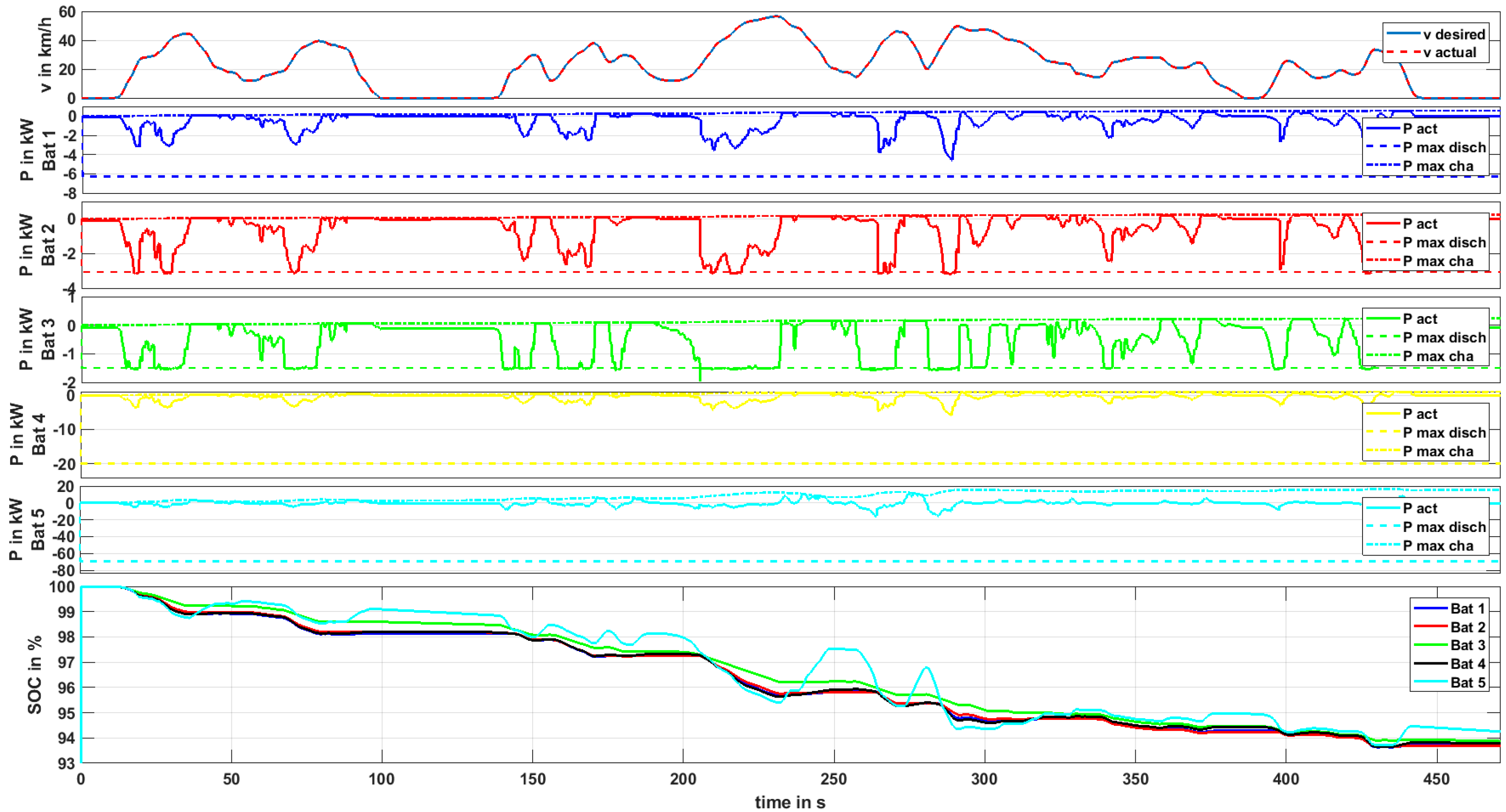
Due to the above-mentioned reasons, a straightforward power distribution algorithm was implemented in this work: it primarily seeks to equalize the state of charge (SoC) of all packs and simultaneously maintains each pack’s individual power limitations. Figure 6 shows an exemplary result using the implemented power distribution logic for five different battery packs in a driving scenario. The power distribution is explained using this excerpt of the scenario.
The uppermost graph in Figure 6 shows the reference speed and the actual vehicle speed controlled by the driver. One can see that the reference speed is met in this example. It is reached by applying a certain drivetrain power, depending on the vehicle’s properties (e.g., front area, chassis mass, tire friction, etc.) and the actual mass of the drivetrain—in many cases, dominated by the battery system. The latter is the reason why, in this tool chain, every new battery system has to be evaluated in the vehicle model, as the battery mass directly influences the vehicle’s traction power requirements.
The very theoretical example in Figure 6 makes use of five equally dimensioned battery packs, each containing cells with a nominal pack energy of approximately 1 kWh. The first pack contains SB LiMotive cells, the second pack contains Kokam cells, the third contains Panasonic cells, the fourth contains A123 cells, and the fifth contains Toshiba cells—all described in Table 1. The different cell characteristics can be clearly seen by the output maximum discharge and charge power limits, indicated by the dashed lines in plots 2–6 in Figure 6. These values are predicted in real time by the modeled battery management systems’ power predictions and thus are cell type and state dependent. High states of charge, for example, lead to a reduction of maximum charging power, in most cases, to prevent overcharging or lithium-plating. The power distribution algorithm works in a way that these limits are never exceeded, while distributing the power to each battery so that the states of charge of all batteries are equalized as much as possible. This strategy can be recognized in the instances of long and powerful recuperation, e.g., at t = 250 s in Figure 6. Battery 5, containing the Toshiba cells (providing a very high charging capability), is charged with a higher current rate than the other packs in this instance. Consequently, the SoC of this pack rises more than the SoC of the other packs. To compensate this mismatch, the power distribution strategy tries to assign relatively more discharge power to this pack in the next acceleration phases. One can see in the bottom plot in Figure 6 that this strategy works well in this scenario, although the packs have such different characteristics—the states of charge can diverge temporarily but are leveled out afterwards. The power distribution algorithm was implemented in Simulink Stateflow and is part of the energy management software. It is used for the tool chain described in this paper. The algorithm is fully generic in a way that up to five batteries can be handled. If fewer batteries are available, the algorithm adapts itself automatically based on missing availability signal of the unavailable packs. If just one pack is in the vehicle, the complete power distribution algorithm is bypassed to save computational effort.
2.3.2. Alternative Power Distribution Algorithms for Defined Hybrid Battery Systems
The implemented power distribution logic is not necessarily the most suitable if the battery system is defined. This means that if one has dimensioned a certain hybrid battery system, the power distribution may be optimized towards a specified objective, knowing the used battery cells and the application in detail. The objective might address an optimization of overall system efficiency. The latter was, for example, investigated for fuel-cell/high power storage hybrids in [29]. Then, a model predictive control-based strategy, which optimizes the system efficiency, was developed for a plug-in EV with a hybrid battery system in [30]. In [31,32], power distribution strategies for hybrid storages were developed utilizing basic filter approaches. Another optimization objective might address the minimization of battery aging. In [31,33,34,35], high-energy storage/supercapacitor hybrids were analyzed for automotive applications. The authors showed that current peaks and, moreover, the root-mean-square current load on the high-energy storage can be reduced. Thereof, they concluded that battery aging can be reduced. Nevertheless, the latter conclusion was not validated by aging measurements utilizing realistic driving-related load profiles.
The optimized power distribution for hybrid battery systems comprising two battery parts was subject to complementary work described in detail in [27,36]. In addition, beneficial aspects of hybrid battery systems comprising a high-energy solid-state lithium metal polymer battery were discussed in [37]. Mainly two types of energy management strategies were introduced in [27]: firstly, a reference solution was calculated offline, gaining the global optimal power distribution for a given driving mission and EV hybrid battery system. The procedure is based on a deterministic dynamic programming algorithm [38]. Secondly, two online energy management strategies were established that allow for an optimized power distribution, though there is no exact knowledge of the future driving mission. One of these strategies considers a stochastic model of the vehicle’s drive mission. The other strategy is based on an instantaneous minimization of battery system energy losses. An equivalence term was added, taking into account a charge-sustaining operation of the high-power battery part. Overall, it was shown that the online energy management approaches allow for a near-optimal power distribution, which is comparable to the offline reference solutions. For example, the stochastic online strategy only shows a maximum of around 8.5% higher battery system energy losses (including dc/dc converters) when comparing it to the offline reference solution.
Moreover, in [36], it was particularly analyzed whether a hybrid battery system can be utilized in order to reduce battery aging. Results were gained from elaborate cycle aging measurements and analysis on the battery cell level. The underlying hybrid battery system comprises the Li-ion cells in presented this work; i.e., the Panasonic high-energy and the Toshiba high-power cells. In comparison to the Panasonic cell, the Toshiba high-power LTO cell showed subordinate aging. Hence, aging investigations were focused on the Panasonic high-energy cell. For real world driving cycle profiles, it was found that the distance-related aging effects on the high-energy cell are largely independent of the level of energy throughput and short duration load profile power peaks for the given test conditions (Panasonic cell, constant 60% depth of discharged energy range, charge protocol, 23 °C cell surface temperature, load profile sequences). Nevertheless, it was then found that increasing recuperation pulse durations caused an acceleration of aging. This result leads to hybrid battery system operation recommendations addressing aging minimization: long time recuperation on the HE battery part should be avoided. In other words, recuperation phases exceeding a charging current rate of 1 C on the cell level and exceeding a duration of 30 s shall be avoided. In fact, these recuperation loads can be shifted to the less sensitive high-power battery part. On the other hand, discharging currents within the high-energy battery’s specifications can be applied on the HE battery without varying its aging behavior.
2.4. Battery Optimization Framework
The design process of a battery system is complex because the dependencies of characteristics spread across the complete development chain: the choice of cell type(s) influences the necessary number of cells for given application requirements, which influences the weight and volume of the pack. The resulting weight and loss power of the cells directly influence acceleration and range characteristics of the vehicle. The cooling system has to be well adapted to the chosen cells and application requirements to maintain the battery cells in their valid temperature range in worst case conditions, while not over-dimensioning the cooling system. Thus, the design process for an EV battery system shows circular dependencies. For a hybrid battery system, the design is even more complex. Assuming that an OEM may choose amongst five different cell technologies or types and also combines them to hybrid systems, the solution space for possible battery systems becomes huge. However, finding the best solution is a complex task. An evolutionary optimization approach (“Covariance Matrix Adaption Evolution Strategy” (CMAES), developed by Hansen et al. [39]) was chosen in this work to solve this multidimensional and nonlinear optimization problem. Evolutionary optimization algorithms work similar to biological evolution: the best individuals of each generation are chosen to create new generations of individuals based on genetic operators. From generation to generation, the best individuals better fit the searched optimum. A major advantage of the chosen optimization approach by Hansen et al. compared to, e.g., genetic algorithms, is the significantly reduced number of parameters that have to be set in order to use the optimization algorithm for a specific problem, since the optimization algorithm adapts itself to the optimization problem. The migration towards the optimum solution is reached by mathematical methods, i.e., adapting the covariance matrix.
In the following, one specific hybrid battery configuration can be, for example, the combination of a pack made of 20 kWh of Panasonic cells and a second pack made of 3 kWh of Toshiba cells. Such a battery configuration is called an individual in the context of evolutionary optimization. In this work, the individual is coded by the energy of each cell type in the five packs:
[ESB LiMotive; EKokam; EPanasonic; EA123; EToshiba]—each given in Wh.
The above-mentioned individual would thus be coded as [0; 0; 20,000; 0; 3000]. The optimizer evaluates a certain number of such individuals in the very first step, called the first generation. The best individuals are then chosen for the next generation of individuals, i.e., the covariance matrix is adapted. Similar to evolutionary theory, the new generations contain individuals which are closer to the problem’s optimum. The key and major task in this process is the individuals’ evaluation. This is done inside the cost function. Besides what the name suggests, it not only calculates the direct costs of the particular individual (i.e., the battery costs) but also assigns penalty points or “costs” if certain requirements of the vehicle are not fulfilled with the chosen battery configuration. Inside the cost function, the vehicle model is used to determine the vehicle’s acceleration, maximum speed, and range for the specified individual under different conditions (warm, cold, beginning of life, after eight years). Simulink’s Rapid-Accelerator mode was used in order to maximize simulation speed. In this mode, an executable is built which contains all components of the model itself, as well as the equation solver. Thus, the model is not interpreted as it is in the case in the Simulink “Normal Mode”. In order to use the executable without modification, the particular settings for each individual—i.e., the battery specifications—are fed into the model using the concept of tunable parameters. This enables very fast simulations and furthermore parallelization of evaluations on multicore CPUs using the same executable with different parameters. If the specified vehicle requirements cannot be reached with the particular battery configuration (e.g., vehicle acceleration too low due to insufficient battery power), then penalty “costs” are assigned (e.g., X $ for every second (s) of acceleration time from standstill to 100 km/h, which is higher than the required acceleration time).
Weight, volume, and investment “costs” can be directly calculated in the cost function without simulation in the vehicle model. While investment costs are calculated in a currency, weight and volume are also converted using a linear penalty “cost” approach. All penalty “cost” factors can be parameterized in accordance to their particular relevance. If, for certain applications, the weight is of higher importance than the volume, the weight penalty “cost” factor can be increased relative to the volume “cost” factor and thus has higher influence on the individual’s evaluation.
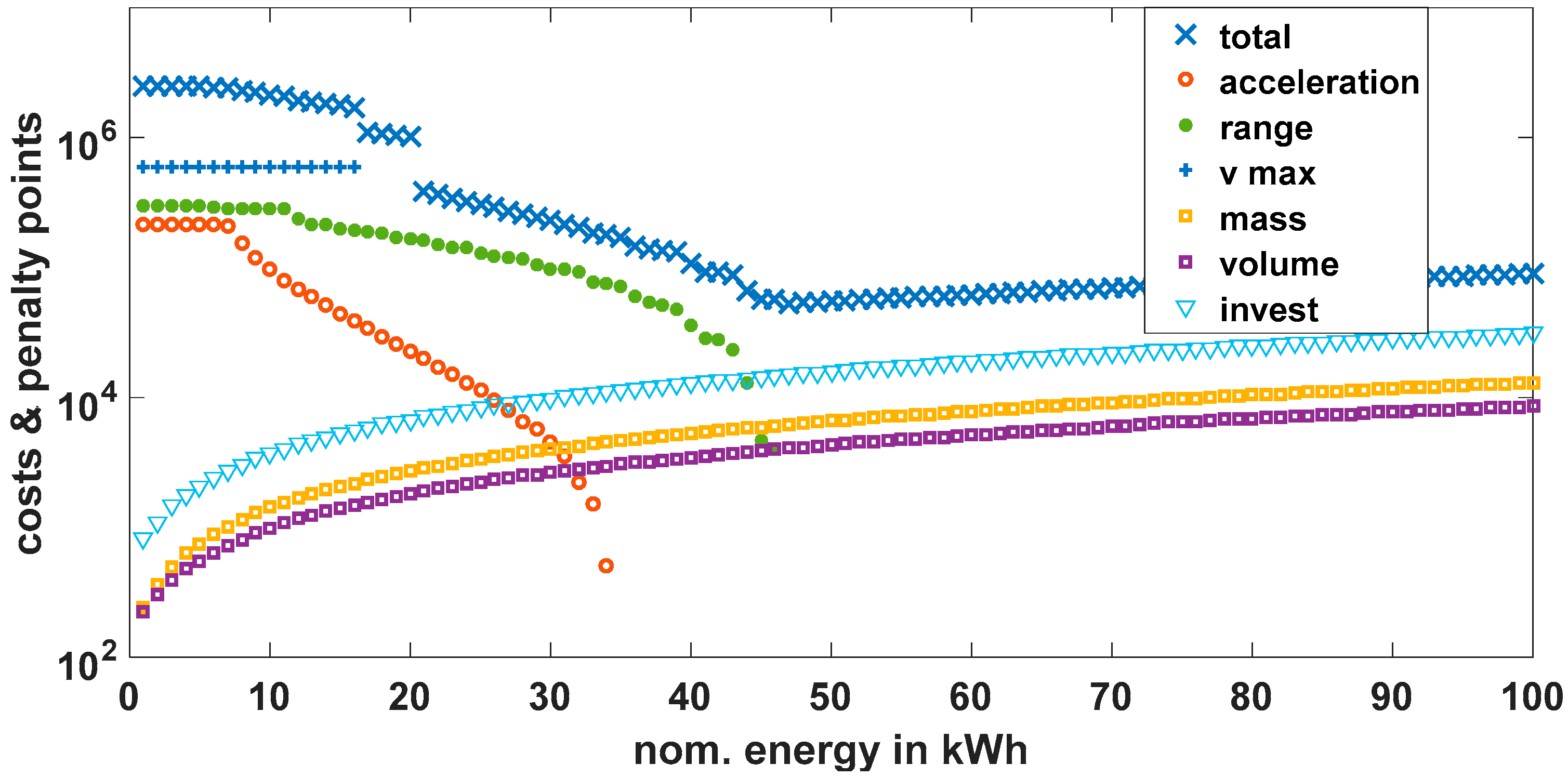
The components of the cost function which are summed to the total costs are visualized in Figure 7 for an example of a single-pack battery system which is iteratively increased in its nominal energy size by 1 kWh steps (x-axis).
Note that the y-axis is logarithmic. Very small battery systems generate very high penalty points, since they cannot fulfill the performance requirements in the vehicle. One can see that from 35 kWh nominal energy upwards, the penalty points for acceleration vanish, meaning that these battery configurations enable the vehicle to accelerate fast enough. Also, from 45 kWh onwards, the penalty points for the range criterion are zero. The total costs thus have a minimum in this range of energy for this particular cell type and vehicle. For even higher energy capacity, the mass and volume increase, which generates higher penalty points again—additional to higher investment costs.
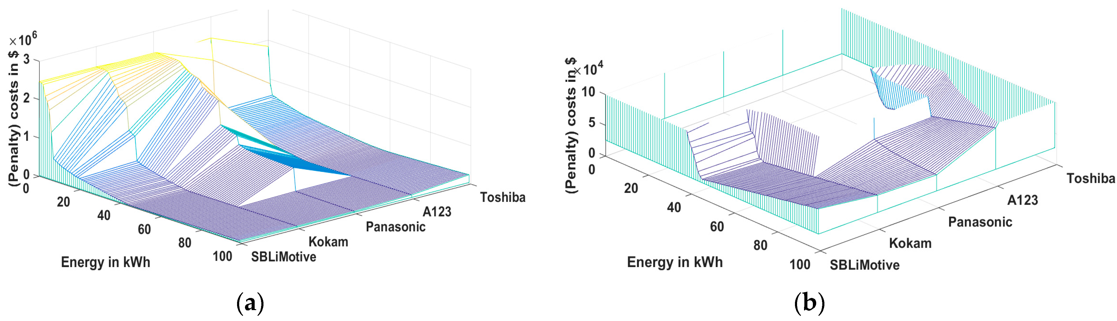
Figure 8 shows the result of the cost evaluation for the five different cell types with different sizing of the packs. The particular cost components (as shown in Figure 7) are not visualized but only the total costs. Similar to Figure 7, one can see a global cost minimum in the range of 50 kWh for packs with SB LiMotive, Kokam, and A123 cells. Due to the limited power of the Panasonic cell, significantly higher energy content is required with this cell type in order to fulfill the acceleration requirement, which is mainly influenced by the cells’ maximum electrical power. Battery systems only containing the Toshiba cell show comparatively high mass and volume figures, which leads to high costs over the complete energy range. A visualization of the cost function’s results for differently sized battery packs, as shown in Figure 8, is only possible for single-pack battery systems, since a combination of cell types leads to a more dimensional solution space. Furthermore, the computational effort to analyze all cell combinations with all sizes (brute force optimization) increases significantly in a hybrid battery approach. This is why a systematic optimization approach was developed in this work and used for different vehicles.
3. Dimensioning Results
To evaluate the concept of hybrid battery systems and compare the approach to the state of the art single battery pack approach, the developed tool chain was used for five different EVs:
- a reference vehicle of the current generation—similar to the first version of the BMW i3—with 150 km range, called “Compact 150 km”;
- a reference vehicle having the same chassis properties as “Compact 150 km” but with 300 km range, called “Compact 300 km”;
- a sportive compact vehicle with chassis properties similar to a BMW M3, with 350 km range and 3.9 s acceleration time from zero to 100 km/h, called “Medium Sport”;
- an upper class vehicle with 400 km range and 5.1 s acceleration time, called “High Class“;
- a large, electrified sports utility vehicle (SUV) with a range of 500 km, accelerating in 5.1 s from standstill to 100 km/h.
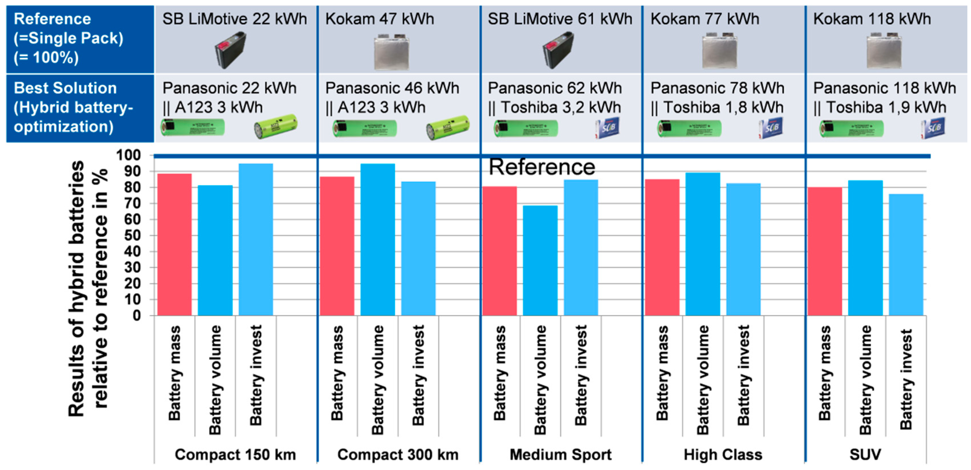
For each of these vehicles, an individual reference battery system was optimized using the full cell portfolio from Table 1. This reference battery was formed out of a certain cell type that best suits the individual vehicle’s requirements. The hybrid battery solutions, described later, are all compared to the individual single-pack reference battery systems. The cell type and battery pack size of these reference packs in terms of energy is indicated in the upper row in Figure 9 for each analyzed vehicle type. The resulting mass, volume, and investment costs of these reference battery systems formed out of one cell type are considered as 100% in the following comparison and in Figure 9 (blue horizontal line). One can observe that in the case of vehicles with a rather high power-to-energy requirement, the SB LiMotive cell turns out to be the best choice for a single-cell battery system (“Compact 150 km” and “Medium Sport”). In the case of the other three vehicles with higher range, and thus higher energy requirements, the Kokam cell with slightly higher energy density is better suited and was chosen by the optimization tool.
Now, after knowing the properties of the reference battery system, the heuristically optimal hybrid battery system was obtained for each vehicle, using the developed hybrid battery dimensioning tool chain. The resulting battery configurations and sizes in terms of energy are indicated in the second row in Figure 9 for each vehicle. The resulting mass, volume, and investment costs of these hybrid battery solutions are finally shown in the lower part of Figure 9, relative to the above-explained reference battery systems. It becomes clear that, in all analyzed cases, the mass, volume, and investment costs of the hybrid batteries are lower compared to the best single-pack system (reference), although these solutions require at least one additional dc/dc converter, as shown in Figure 2. As mentioned before, the solutions shown in this work were obtained using two dc/dc converters, as shown in Figure 2b. Furthermore, the results show that the combination of a HE Panasonic cell and a high-power cell leads to the best combinations for all vehicles. In the case of the vehicles with moderate acceleration performance, the A123 cell turns out to be the better option, in combination with the Panasonic cell. In the case of the vehicles with higher mass or higher specified acceleration power, the Toshiba cell is better suited.
The highest reduction potential in battery mass through hybridization is obtained in the case of the large electric SUV (20%). The battery volume reduction compared to the reference is the largest in the case of the Medium Sport vehicle (31%). The highest cost reduction potential is again gained in the case of the SUV (24%). The lowest mass reduction effects through battery hybridization are obtained with the two compact EVs, both in the range of 11–13%, the lowest volume reduction with the “Compact 300 km” (5%), and the lowest cost reduction with the “Compact 150 km” (5%). The results are discussed in the following section.
4. Discussion
As shown in the previous section, the hybridization of battery systems with a high-energy and a high-power part may result in considerable weight, volume, and cost savings, although at least one additional dc/dc converter is required, as indicated in Figure 2. This is due to the fact that the significantly higher energy density of the high-energy battery cell and the higher power density of the high-power cell overcompensate for the disadvantages of the additional converter. The overall energy density of the hybrid battery systems (including the power electronics) is higher than the energy density of the reference battery systems. At the same time, the hybrid battery systems fulfill the power requirements, since the high-power part of the system shows very high peak power capabilities.
Furthermore, the hybrid battery approach allows tailoring of the battery system’s energy and power capability exactly to the requirements for each vehicle. This fact plays a further important role as soon as OEMs begin electrifying a wider range of their offered vehicle fleet. Then, two types of battery cells may, in the best case, qualify for the complete range of vehicles in differently scaled versions of high-energy and high-power packs, as shown in the previous section and in Figure 9. Note that the corresponding optimization results for the analyzed vehicles using just the Panasonic and the Toshiba cell type (instead of the A123 cell for the two compact vehicles) were very close to the optimum results shown here.
It is foreseeable that new battery technologies with even higher energy density will follow the current Li-ion cell technology, e.g., Li-sulfur or solid-state batteries [37]. Using such cells will presumably further decrease the battery system costs (per energy). These new cells will, on the other hand, suffer from some disadvantages—most probably, lower power capability, at least in some operating points. Nevertheless, such cells may be perfectly suited for vehicle applications when combined with a high-power battery pack, as discussed in this work. Then, the peak power is delivered or absorbed by the high-power pack. Moreover, the shift of loads to a high-power battery pack might lead to a reduction of cycle aging on the high-energy battery pack, which is based on new battery technologies.
Since hybrid battery systems require additional power electronics, these batteries are more complex to control than systems with just one battery type. Possible ways to control the power between the available packs are described in this work. In addition to the higher complexity, power electronic systems may also suffer from failures, which increases the failure probability of the battery system in the first place. However, the overall availability of the hybrid battery system may even be better than a single-pack system, since a proper setup may allow an emergency or limp-home mode if one of the packs or converters fails. This has to be quantified in further research by combining failure rates of cells, battery strings, and topologies [40], as well as power electronic devices in the context of modularized battery systems. Availability of battery systems will certainly become one of the most important figures in future highly automated electric vehicles.
In general, the hybrid battery approach can be extended to other applications besides vehicles. It is well suited in cases with significantly varying electrical power demands, where the high-energy part can be discharged at a rather constant rate and the high-power part delivers or absorbs the higher loads. Such applications can be electric railways running without catenary system, marine systems, or airborne systems.
Finally, it has to be noted that the hybrid battery approach does not solve the “problem” of fast charging batteries to drive vehicles over longer distances with minimal stops for recharging. Although the system can absorb high electric loads for short times due to the high-power part (e.g., lithium titanate oxide), the energy which can be fast charged is more or less limited to the high-power part. This part usually will be significantly smaller in terms of energy, which can be seen in Figure 9. Consequently, the charging duration for a full charge of the hybrid systems indicated in the previous section may be the same or even longer than the charging duration of the reference systems, since the hybrid systems discussed in this work make use of consumer cells, which are not optimized for high-power charging but for high energy densities.
5. Conclusions
This work describes a methodology for the optimization of hybrid battery systems for automotive applications. These battery systems can consist of different battery cell technologies, which are connected by dc/dc converters on the pack level. The combination may consist of cells of different electrode materials and thus different voltage characteristics.
After defining the requirements for a certain vehicle (e.g., acceleration, maximum speed, and range), as well as setting a cell portfolio, the developed tool automatically searches for the battery system solution, which generates the least penalty points for weight, volume, and the least investment costs. The optimization criteria can be prioritized according to the set penalty points for each evaluation criterion by adjusting the penalty cost factor for each property. The search algorithm makes use of the evolutionary optimization approach “Covariance Matrix Adaption Evolution Strategy” (CMAES).
The obtained results show that the hybrid battery approach can generate significant advantages concerning weight, volume, and investment costs for the investigated vehicle classes. The concept allows exact dimensioning of both energy and power simultaneously, while using the best properties of two battery technologies. With the developed tool, the hybrid approach was evaluated by optimizing two types of battery systems for five different vehicle types. The best single pack approach—serving as a reference—as well as the best hybrid battery approach were determined for each vehicle. It was observed that the weight advantage of the hybrid battery system was at least 11% for the smaller cars but up to 20% for the high-range and high-power SUV. Similar results were obtained for the volume reduction potential (5% for the compact car with 300 km range and up to 31% for the medium sport vehicle). The cost-saving potential using hybrid battery systems ranges from a negligible 5% for the compact vehicle up to 24% for the SUV. The results show that in the investigated cases, the weight, volume, and cost advantages compensate for the additional weight, volume, and costs of the required power electronics, which are included in the given numbers. The analysis also shows that the cells and the energy content of each battery pack must be carefully chosen and dimensioned for the investigated vehicles.
Future extensions of the analysis have to cover the best modularization for multivehicle usage of battery types, e.g., cross-platform for a complete fleet of vehicles. Furthermore, the analysis has to be extended to other vehicle classes, like electric buses and light trucks or even different applications, e.g., railway.
Author Contributions
Conceptualization, J.B.; Formal analysis, T.N.; Methodology, J.B., T.N., R.W. and D.U.S.; Supervision, D.U.S.; Writing-original draft, J.B. and R.W.; Writing-review & editing, T.N. and D.U.S.
Funding
This research “HV-ModAL” was funded by the Federal Ministry of Education and Research (BMBF).
Acknowledgments
The authors would like to thank the Federal Ministry of Education and Research (BMBF) for funding the research project “HV-ModAL” and the project partners AVL Software Functions GmbH, AVL Trimerics GmbH, BMW AG, Robert Bosch GmbH, Daimler AG, Fraunhofer Institute for Integrated Systems and Device Technology IISB, Chair of Electrical Drives and Actuators (EAA) at UniBwM, Infineon Technologies AG, Institute for Drive Systems and Power Electronics at IAL for their excellent collaboration on the topics of modular drive trains.
Conflicts of Interest
The authors declare no conflict of interest. The founding sponsors had no role in the design of the study; in the collection, analyses, or interpretation of data; in the writing of the manuscript, and in the decision to publish the results.
References
- National Platform for Electromobility (NPE). Second Report of the National Platform for Electromobility; Federal Government Joint Unit for Electromobility Scharnhorststr: Berlin, Germany, 2011; pp. 34–37. [Google Scholar]
- Ciez, R.E.; Whitacre, J. Comparison between cylindrical and prismatic lithium-ion cell costs using a process based cost model. J. Power Sources 2017, 340, 273–281. [Google Scholar] [CrossRef]
- Reber, V. e-Power—New Possibilities with 800-Volt Charging. Porsche Eng. Mag. 2017, 367, 216–227. [Google Scholar]
- Kowal, M.; Blank, T.; Senol, M.; Sauer, D.U.; De Doncker, R.W. Optimized voltage range for future electric and hybrid-electric vehicles. In Proceedings of the International Conference and Exhibition Automotive Power Electronics, La Ferme du Manet, Montigny Le Bretonneux, France, 6 April 2011. [Google Scholar]
- Simonite, T. Gadgets Could Get Longer Lives by Combining Batteries. Available online: https://www.technologyreview.com/s/541861/gadgets-could-get-longer-lives-by-combining-batteries/ (accessed on 27 June 2018).
- Catherino, H.A.; Burgel, J.F.; Shi, P.L.; Rusek, A.; Zou, X. Hybrid power supplies: A capacitor-assisted battery. J. Power Sources 2006, 162, 965–970. [Google Scholar] [CrossRef]
- Dougal, R.A.; Liu, S.; White, R.E. Power and life extension of battery–ultracapacitor hybrids. IEEE Trans. Compon. Packag. Technol. 2002, 25, 120–131. [Google Scholar] [CrossRef]
- Rosario, L.; Luk, P.-K. Applying management methodology to electric vehicles with multiple energy storage systems. In Proceedings of the 2007 International Conference on Machine Learning and Cybernetics, Hong Kong, China, 19–22 August 2007; pp. 4223–4230. [Google Scholar]
- Tutuianu, M.; Marotta, A.; Steven, H.; Ericsson, E.; Haniu, T.; Ichikawa, N.; Ishii, H. Development of a World-Wide Worldwide Harmonized Light Duty Driving Test Cycle (WLTC); Technical Report, UN/ECE/WP.29/GRPE/WLTP-IG; DHC Subgroup. 2013. Available online: http://www.unece.org.net4all.ch/fileadmin/DAM/trans/doc/2014/wp29grpe/GRPE-68-03e.pdf (accessed on 27 June 2018).
- Kutscher, J.; Le, K.-B.; Spelten, W. The New Smart Electric Drive—Perfect Drive for the Perfect City Car; Technical Report, Daimler Communications; 2017. Available online: http://media.daimler.com/marsMediaSite/ko/en/15575961 (accessed on 27 June 2018).
- Fisher, T. What Goes into A Tesla Model S Battery–And What It May Cost; 2013. Available online: http://www.greencarreports.com/news/1084682_what-goes-into-a-tesla-model-s-battery--and-what-it-may-cost (accessed on 27 June 2018).
- Gaines, L.; Cuenca, R. Costs of Lithium-Ion Batteries for Vehicles; Technical Report; Argonne National Laboratory: Argonne, IL, USA, 2000.
- Nelson, P.A.; Santini, D.J.; Barnes, J. Factors Determining the Manufacturing Costs of Lithium-Ion Batteries for PHEVs; Center for Transportation Research, Argonne National Laboratory: Stavanger, Norway, 2009.
- Nelson, P.; Gallagher, K.; Bloom, I. BatPaC: A Lithium-Ion Battery Performance and Cost Model for Electric-Drive Vehicles; Technical Report; Chemical Science and Engineering Division, Argonne National Laboratory: Argonne, IL, USA, 2015.
- Nelson, P.A.; Gallagher, K.G.; Bloom, I.; Dees, D.W. Modeling the Performance and Cost of Lithium-Ion Batteries for Electric-Drive Vehicles, 2nd ed.; Technical Report; Argonne National Laboratory, U.S. Department of Energy Office of Scientific and Technical Information: Oak Ridge, TN, USA, 2012.
- Menahem, A. The Tesla Battery Report; Technical Report; Total Battery Consulting, Inc.: Oregon House, CA, USA, 2014. [Google Scholar]
- BMW USA. i3s with Range Extender Standard Features. 2018. Available online: https://www.bmwusa.com/vehicles/bmwi/bmw-i3/bmw-i3s-with-range-extender.html (accessed on 27 June 2018).
- Giuliani, S. VW e-Golf. 2014. Available online: https://www.adac.de/_ext/itr/tests/Autotest/AT5134_VW_e_Golf/VW_e_Golf.pdf (accessed on 27 June 2018).
- Renault Press. Renault ZOE—Technical Specification; Technical Report; 2016. Available online: https://media.group.renault.com/global/en-gb/download/84850 (accessed on 27 June 2018).
- Ecker, M.; Nieto, N.; Käbitz, S.; Schmalstieg, J.; Blanke, H.; Warnecke, A.; Sauer, D.U. Calendar and cycle life study of Li(NiMnCo)O2-based 18650 lithium-ion batteries. J. Power Sources 2014, 248, 839–851. [Google Scholar] [CrossRef]
- Schmalstieg, J.; Käbitz, S.; Ecker, M.; Sauer, D.U. A holistic aging model for Li(NiMnCo)O2 based 18650 lithium-ion batteries. J. Power Sources 2014, 257, 325–334. [Google Scholar] [CrossRef]
- Ecker, M.; Käbitz, S.; Gerschler, J.; Sauer, D.U. Modeling of Lithium Plating in Lithium-Ion Batteries; Meeting Abstracts MA2010-02; 2010. Available online: http://ma.ecsdl.org/content/MA2010-02/4/201.abstract (accessed on 27 June 2018).
- Warnecke, A.J. Degradation Mechanisms in NMC-Based Lithium-Ion Batteries. Ph.D. Dissertation, RWTH Aachen University, Aachen, Germany, 2017. [Google Scholar]
- Zhang, Y.; Jiang, Z. Dynamic power sharing strategy for active hybrid energy storage systems. In Proceedings of the 2009 IEEE Vehicle Power and Propulsion Conference, Dearborn, MI, USA, 7–10 September 2009; pp. 558–563. [Google Scholar]
- Takeda, K.; Takahashi, C.; Arita, H.; Kusumi, N.; Amano, M.; Emori, A. Design of hybrid energy storage system using dual batteries for renewable applications. In Proceedings of the 2014 IEEE PES General Meeting|Conference Exposition, National Harbor, MD, USA, 27–31 July 2014; pp. 1–5. [Google Scholar]
- Carter, R.; Cruden, A. Strategies for control of a battery/supercapacitor system in an electric vehicle. In Proceedings of the 2008 International Symposium on Power Electronics, Electrical Drives, Automation and Motion, Ischia, Italy, 11–13 June 2008; pp. 727–732. [Google Scholar]
- Wegmann, R.; Döge, V.; Becker, J.; Sauer, D.U. Optimized operation of hybrid battery systems for electric vehicles using deterministic and stochastic dynamic programming. J. Energy Storage 2017, 14, 22–38. [Google Scholar] [CrossRef]
- Qiao, Z.; Deng, W.; Wu, J.; Ju, F.; Li, J. Development of Battery/Supercapacitor Hybrid Energy Management System for Electric Vehicles Based on a Power Sharing Strategy Using Terrain Information; SAE Technical Paper; SAE 2016 World Congress and Exhibition: Detroit, MI, USA, 2016. [Google Scholar]
- Odeim, F.; Roes, J.; Wülbeck, L.; Heinzel, A. Power management optimization of fuel cell/battery hybrid vehicles with experimental validation. J. Power Sources 2014, 252, 333–343. [Google Scholar] [CrossRef]
- Zhang, S.; Xiong, R.; Sun, F. Model predictive control for power management in a plug-in hybrid electric vehicle with a hybrid energy storage system. Appl. Energy 2017, 185, 1654–1662. [Google Scholar] [CrossRef]
- Castaings, A.; Lhomme, W.; Trigui, R.; Bouscayrol, A. Comparison of energy management strategies of a battery/supercapacitors system for electric vehicle under real-time constraints. Appl. Energy 2016, 163, 190–200. [Google Scholar] [CrossRef]
- Simmons, K.; Guezennec, Y.; Onori, S. Modeling and energy management control design for a fuel cell hybrid passenger bus. J. Power Sources 2014, 246, 736–746. [Google Scholar] [CrossRef]
- Shen, J.; Dusmez, S.; Khaligh, A. Optimization of sizing and battery cycle life in battery/ultracapacitor hybrid energy storage systems for electric vehicle applications. IEEE Trans. Ind. Inform. 2014, 10, 2112–2121. [Google Scholar] [CrossRef]
- Shen, J.; Khaligh, A. A supervisory energy management control strategy for a battery/ultracapacitor hybrid energy storage system. IEEE Trans. Transp. Electrif. 2015, 1, 223–231. [Google Scholar] [CrossRef]
- Zhang, S.; Xiong, R.; Cao, J. Battery durability and longevity based power management for plug-in hybrid electric vehicle with hybrid energy storage system. Appl. Energy 2016, 179, 316–328. [Google Scholar] [CrossRef]
- Wegmann, R.; Döge, V.; Sauer, D.U. Assessing the potential of a hybrid battery system to reduce battery aging in an electric vehicle by studying the cycle life of a graphite∣NCA high energy and a LTO∣metal oxide high power battery cell considering realistic test profiles. Appl. Energy 2018, 226, 197–212. [Google Scholar] [CrossRef]
- Wegmann, R.; Döge, V.; Sauer, D.U. Assessing the potential of an electric vehicle hybrid battery system comprising solid-state lithium metal polymer high energy and lithium-ion high power batteries. J. Energy Storage 2018, 18, 175–184. [Google Scholar] [CrossRef]
- Bellman, R. Dynamic Programming, 1st ed.; Princeton University Press: Princeton, NJ, USA, 1957. [Google Scholar]
- Hansen, N.; Kern, S. Evaluating the CMA Evolution Strategy on Multimodal Test Functions; Springer: Berlin/Heidelberg, Germany, 2004; pp. 282–291. [Google Scholar]
- Lehner, S. Reliability Assessment of Lithium-Ion Battery Systems with Special Emphasis on Cell Performance Distribution. Ph.D. Thesis, RWTH Aachen University, Aachen, Germany, 2017. [Google Scholar]
Figure 1.
Dimensioning of a battery system. (a) Using just one type of cell; (b) using a hybrid approach with two kinds of cells.
Figure 1.
Dimensioning of a battery system. (a) Using just one type of cell; (b) using a hybrid approach with two kinds of cells.

Figure 2.
Hybrid battery system topologies using dc/dc converters. (a): Only one of the packs is connected with a dc/dc converter to the dc link. The voltage of the dc link is determined by the clamp voltage of pack 2. (b): Both packs are equipped with a dc/dc converter, which allows setting the dc-link voltage independently of the pack voltages.

Figure 3.
Concept of battery optimization methodology in combination with the vehicle model.
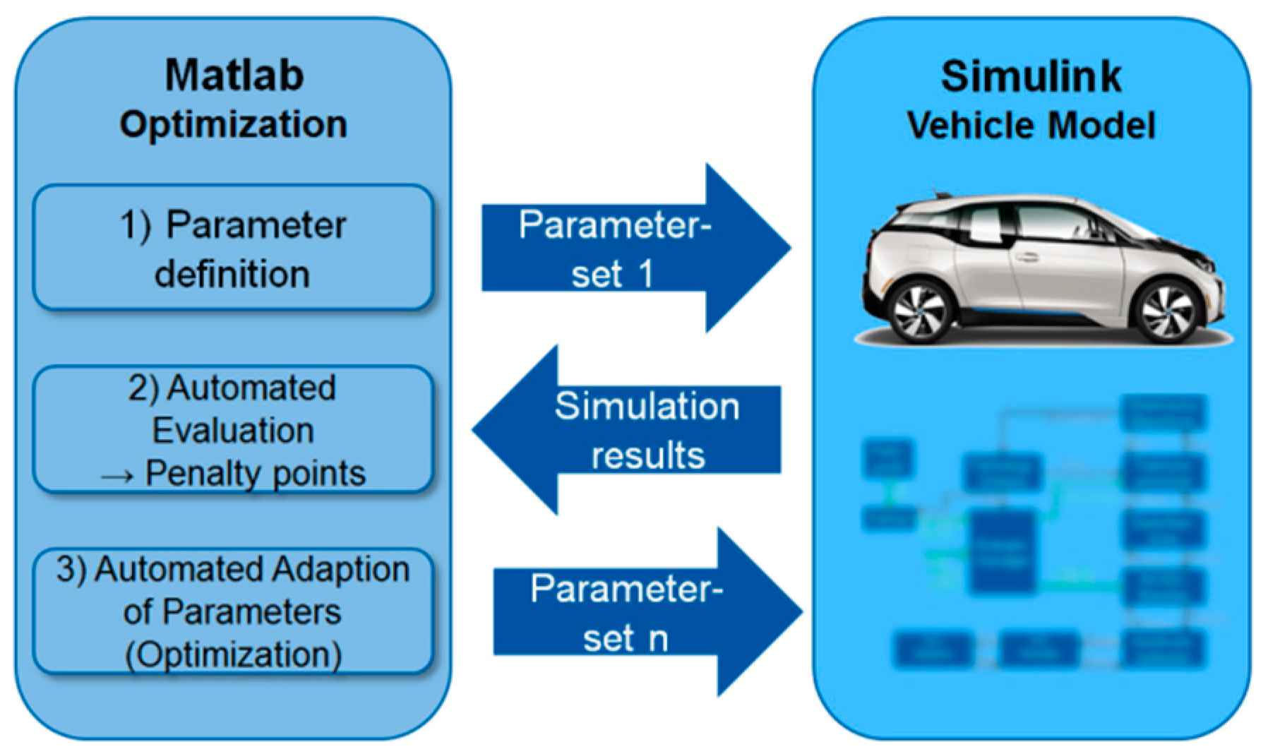
Figure 4.
Battery model structure.

Figure 5.
Energy management controlling the power distribution to the individual battery packs.
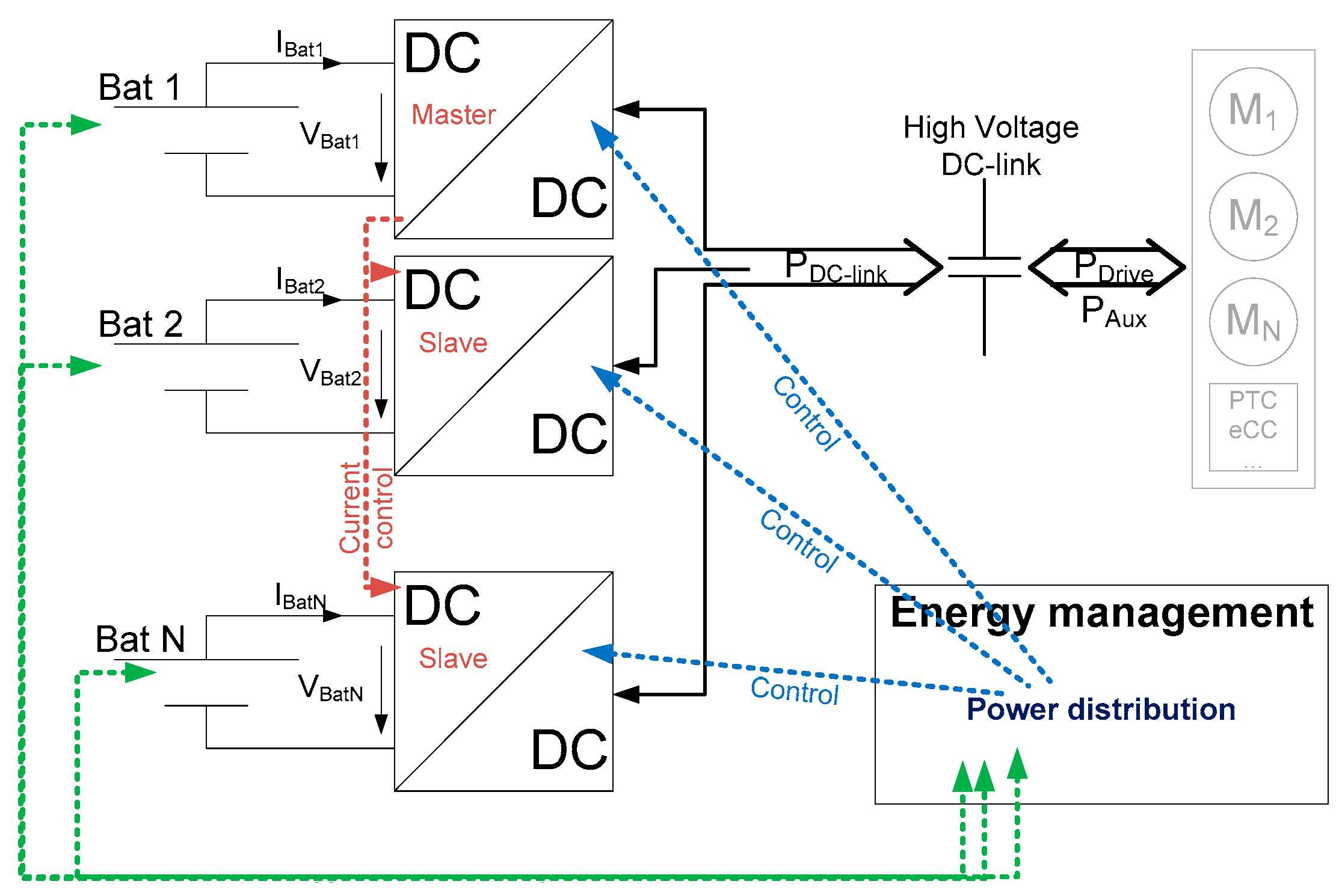
Figure 6.
Example of the implemented power distribution for five different battery packs, each with 1 kWh of different cells.
Figure 6.
Example of the implemented power distribution for five different battery packs, each with 1 kWh of different cells.

Figure 7.
Costs and penalty points evaluated in the cost function of the battery optimization tool box for a single-cell battery system of different sizes.
Figure 7.
Costs and penalty points evaluated in the cost function of the battery optimization tool box for a single-cell battery system of different sizes.

Figure 8.
Costs for different single-pack battery systems with different cell types and different energy content for (a) full cost range; (b) only the relevant cost range—irrelevant configurations are not shown.
Figure 8.
Costs for different single-pack battery systems with different cell types and different energy content for (a) full cost range; (b) only the relevant cost range—irrelevant configurations are not shown.

Figure 9.
Battery optimization results for different vehicle types for single-type battery systems (reference) and hybrid battery systems.
Figure 9.
Battery optimization results for different vehicle types for single-type battery systems (reference) and hybrid battery systems.

Table 1.
Battery cell types of the used cell portfolio.
| CharacteristicCell Type | SB LiMotive | Kokam 46 Ah | Panasonic NCR18650B | A123 26650 M1B | Toshiba 2.9 Ah |
|---|---|---|---|---|---|
| Cell format | prismatic | pouch bag | cylindrical | cylindrical | prismatic |
| HE/HP 1 | HE/HP | HE | HE | HP | HP |
| Electrode composition (cathode vs. anode) | NMC/LMO-blend vs. graphite | NMC vs. graphite | NCA vs. (silicon doped) graphite | LFP vs. graphite | LMO vs. LTO |
| Nom. capacity | 60 Ah | 46 Ah | 3.25 Ah | 2.5 Ah | 2.9 Ah |
| Nom. voltage | 3.75 V | 3.7 V | 3.6 V | 3.3 V | 2.4 V |
| Grav. energy density | 123 Wh/kg | 144 Wh/kg | 241 Wh/kg | 109 Wh/kg | 46 Wh/kg |
| Grav. power density 2 | 860 W/kg | 433 W/kg | 362 W/kg | 2170 W/kg | 3200 W/kg |
| Relative costs | 304 $/kWh | 264 $/kWh | 153 $/kWh | 360 $/kWh | 899 $/kWh |
| Cyclic aging rate relative to reference (in terms of equivalent full cycles) | 1 | 1.4 | 1.6 | 1.33 | 0.2 |
1 HE: high energy, HP: high power; NMC: nickel manganese cobalt oxide; NCA: nickel cobalt aluminum oxide; LFP: lithium iron phosphate; LTO: lithium titanate oxide. 2 In discharge direction at high state of charge (SoC) and with 10 s pulses.
© 2018 by the authors. Licensee MDPI, Basel, Switzerland. This article is an open access article distributed under the terms and conditions of the Creative Commons Attribution (CC BY) license (http://creativecommons.org/licenses/by/4.0/).
Share and Cite
MDPI and ACS Style
Becker, J.; Nemeth, T.; Wegmann, R.; Sauer, D.U. Dimensioning and Optimization of Hybrid Li-Ion Battery Systems for EVs. World Electr. Veh. J. 2018, 9, 19. https://doi.org/10.3390/wevj9020019
AMA Style
Becker J, Nemeth T, Wegmann R, Sauer DU. Dimensioning and Optimization of Hybrid Li-Ion Battery Systems for EVs. World Electric Vehicle Journal. 2018; 9(2):19. https://doi.org/10.3390/wevj9020019
Chicago/Turabian StyleBecker, Jan, Thomas Nemeth, Raphael Wegmann, and Dirk Uwe Sauer. 2018. "Dimensioning and Optimization of Hybrid Li-Ion Battery Systems for EVs" World Electric Vehicle Journal 9, no. 2: 19. https://doi.org/10.3390/wevj9020019