Article

Towards Horizontal Architecture for Autonomic M2M Service Networks

1
VTT Technical Research Centre of Finland, Kaitoväylä 1, Oulu, Finland
2
LAAS-CNRS, 7 Av, C. Roche, 31077 Cedex 04, Toulouse, France
3
Gemalto, 6 rue de la Verrerie, Meudon 92197, France
4
Bull SAS, 207 Cours du Medoc, Bordeaux 33000, France
5
Thales Communications & Security S.A., 160 Boulevard de Valmy, BP 82. 92704, Colomber, France
6
Atos Origin, Diagonal 200, 08018, Barcelona, Spain
7
Polar Elektro Oy, Professorintie 5, Kempele, Finland
*
Author to whom correspondence should be addressed.
Future Internet 2014, 6(2), 261-301; https://doi.org/10.3390/fi6020261
Submission received: 9 January 2014 / Revised: 13 March 2014 / Accepted: 8 April 2014 / Published: 6 May 2014
(This article belongs to the Special Issue Toward people aware IoT)

Abstract

:
Today, increasing number of industrial application cases rely on the Machine to Machine (M2M) services exposed from physical devices. Such M2M services enable interaction of physical world with the core processes of company information systems. However, there are grand challenges related to complexity and “vertical silos” limiting the M2M market scale and interoperability. It is here expected that horizontal approach for the system architecture is required for solving these challenges. Therefore, a set of architectural principles and key enablers for the horizontal architecture have been specified in this work. A selected set of key enablers called as autonomic M2M manager, M2M service capabilities, M2M messaging system, M2M gateways towards energy constrained M2M asset devices and creation of trust to enable end-to-end security for M2M applications have been developed. The developed key enablers have been evaluated separately in different scenarios dealing with smart metering, car sharing and electric bike experiments. The evaluation results shows that the provided architectural principles, and developed key enablers establish a solid ground for future research and seem to enable communication between objects and applications, which are not initially been designed to communicate together. The aim as the next step in this research is to create a combined experimental system to evaluate the system interoperability and performance in a more detailed manner.

1. Introduction

The number of embedded devices has continuously increased in recent years. Traditionally, such devices have worked locally in an independent way and provided services for human users. Advances in radio communication technologies have enabled even mobile connectivity for the referred devices over the Internet. These trends are now visible as the increasing number of application cases which rely on the services exposed from physical equipment, such as sensors, actuators, RFID (Radio Frequency Identification) tags, machines, vehicles and industrial embedded devices. Such service systems are here called as Machine to Machine (M2M) service networks, which can also be called as Internet of Things (IoT) or Cyber-Physical Systems [1]. Usually such systems include capabilities for remote measurements and remote control of embedded devices. Remote measurements consist of sensing physical phenomenon, storing, sending, receiving and processing of measured information. Remote control of devices includes access control, mutual exclusion, sending, receiving and processing of control commands. The basic enabler of such functionality is M2M connectivity, where various kinds of embedded devices are connected into the Internet. The added value is created by the enabled M2M services based on the use of the measured information in a smart way, and reasoning and execution of smart remote control actions with the M2M asset devices.
There are many research challenges related to details of such system and processes, for example identification, sensing/actuation, low-power communication, distributed intelligence, information semantics, data confidentiality, privacy, trust, etc. [1]. However, it is here estimated that even bigger challenge for the society arise from the complexity and fragmented vertical M2M markets. The origin for the complexity is due to the number of embedded devices, connectivity means, service platforms, information management and especially their heterogeneity. In addition, establishing and maintaining an interactive system capable for interoperation with the human user is here expected to go soon beyond human capabilities. M2M market is fragmented to multiple vertical industries, and the resulting systems are usually domain or vendor specific closed systems, also be called as “vertical silos”. In addition, the natural needs of businesses to protect themselves seem to lead such systems which require special access rights for each specific system, resulting in vendor specific closed systems. This has caused problems for example in residential home environments and prevented the emergence of home automation in large extent. Smart grid solutions cannot interoperate with infrastructure and buildings/homes, even if it would be strongly required to reach higher level energy efficiency. Therefore, it is observed here that the technological complexity and vertical M2M silos are the reason of a grand research challenge for development of a modern ecosystem. Because most of the existing vertical systems have difficulty in scaling, it has been seen that enabling horizontal model is important for realizing embedded M2M [2]. Therefore, it is assumed here that solving this grand challenge requires first to have clear principles for the horizontal system architecture; otherwise, the detailed solutions could be applicable only for specific vertical application cases and have thus difficulty in scaling.
There are different technical architectural approaches for M2M systems such as e.g., end-to-end Internet approach [3,4], and M2M gateway based approach [5,6]. It is possible to establish an Internet connection from an Internet node to the M2M asset device without any additional intermediate node making transformation into the messages in the end-to-end Internet based approach, if there is at least tiny Internet protocol (IP) stack also in small embedded devices. This is possible to be done even for such small devices by relying power efficient physical layer and Internet Engineering Task Force (IETF) IPv6 Low Power wireless Area Networks (6LowPAN) adaptation layer enabling universal Internet connectivity, the IETF Routing Over Low power and Lossy networks (ROLL) routing protocol enabling availability, and IETF Constrained Application Protocol (CoAP) enabling seamless transport and support of Internet applications [7,8,9,10,11,12,13,14,15]. However, the challenge is that also the embedded devices which are not Internet capable would be required to connect into the Internet. M2M gateway based approach may enable also their connectivity, however, the challenge may be dynamic behavior of wireless systems and need to adapt with different kinds of service back-end systems. For example, M2M service capability layer aims to solve the heterogeneity challenge of the service systems by providing a standard based set of M2M service capabilities, which could be applied by multiple application domains [16,17,18]. In this model, devices and applications communicate via an M2M service platform, exposing a number of services which, in addition to boosting interoperability, will simplify and reduce the cost of M2M applications development. However, there is heterogeneity also in the technologies related to communication, information layers, security and device management. For example, there are standards such as Open Mobile Alliance Device Management (OMA-DM) [19], Device data model of Broadband Forum (BBF-069) [20], Universal Plug and Play (UPnP) [21], Device Profile for Web Services (DPWS) [22], Open Building for information exchange (oBix) [23], Open productivity and connectivity (OPC) [24], Web Ontology language (OWL) [25], and Open Geospatial Consortium Sensor Web Enablement (OGC-SWE) [26,27,28,29,30,31] dealing with M2M information, service and devices. There are communication technologies, such as e.g., Simple mail transfer protocol (SMTP), Extensible Messaging and Presence Protocol (XMPP) [32,33,34], MQ Telemetry Transport (MQTT), and Session Initiation Protocol (SIP). Security is often addressed using proprietary solutions and the business party in charge of the application deployment is typically assuming the task of credential distribution. There are separate solutions for security in Local Area Network (LAN) device domains, network security to enable secure network access and security technologies applicable for application layer [35,36,37]. In addition, there are a number of forums focused to specify means to be applied within a single application domain and/or with specific type of devices, e.g., video devices, sensors, smart energy meters, medical devices, user interfaces, building automation, automation in the smart grids, etc. And different kinds of approaches for autonomic computing are discussed in e.g., [38,39,40,41,42,43,44,45,46,47,48,49,50]. A detailed comparison of the referred technologies has been provided in [5]. As the result of the referred comparison, it is seen that principles for the architecture are needed in order to establish a solid basis for multiple stakeholder system for M2M service networks. It is assumed in this work, that both end-to-end Internet approach, and M2M gateway based approach are needed to enable horizontally capable M2M service networks. In addition, architecture principles for solving the heterogeneity of technologies are needed to enable communication between objects and applications, which are not initially been designed to communicate together.
The key novel contribution of this paper is related to the architectural principles for the autonomic M2M service networks relying on the horizontal approach, created key enablers called as autonomic M2M manager, M2M service capabilities, M2M messaging system, M2M gateways towards energy constrained M2M asset devices and creation of trust to enable end-to-end security for M2M applications and their experimental based evaluation with three different cases dealing with smart metering, car sharing and electric bike systems. The same type of challenges have also been focused e.g., within FI-Ware [51] Public Private Partnership (PPP) project, which has created an IoT platform, architecture and a set of generic elements related to cloud hosting, data/context management, IoT services enablement, application/services ecosystem and delivery framework, security and Interface to Networks and Devices (I2ND). However, it is seen that the approaches are different in the sense that we rely more on open standards and have an open multiple stakeholder system as the goal, and FI-Ware is more relying on open application programming interface (API) based implementations of specific industrial companies. There are also other projects which are/have been working in the area such as e.g., Hydra [52], Runes [53], IoT-A [54], iCore [55] and Sofia [56]. Each of these projects has specific contributions to be added, however, they have still not solved the described grand challenges related to the technological complexity and vertical M2M silos.
The rest of this article is organized as follows. The architectural principles are defined in Section 2. The key building blocks are described in Section 3. Experimental evaluations are discussed in Section 4. Finally, conclusions are provided in Section 5.

2. Architectural Principles
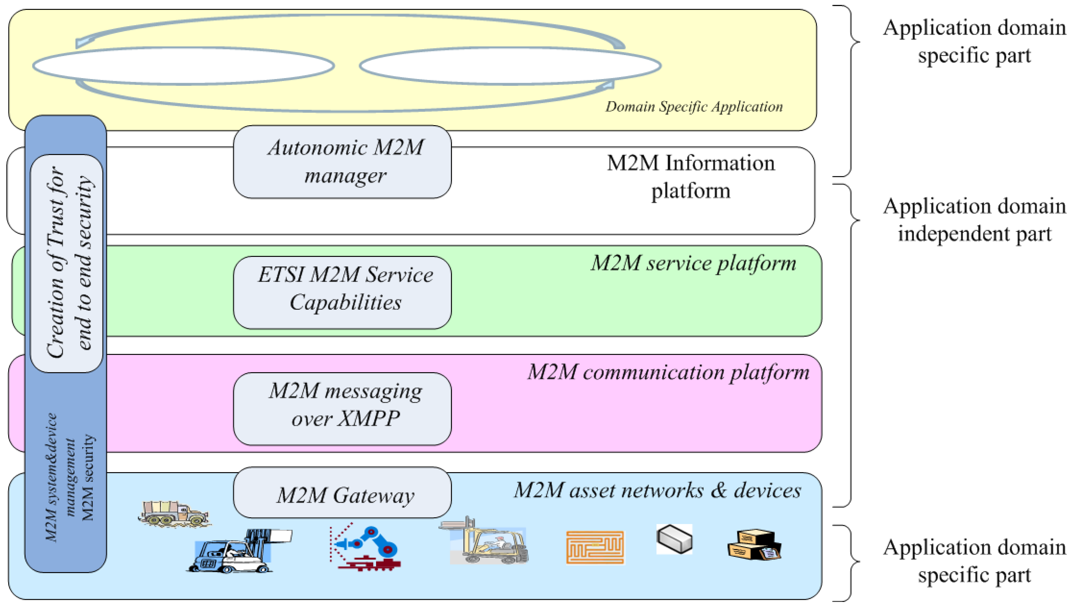
2.1. Horizontal M2M

M2M service networks are inherently multiple stakeholder systems. Some parts of the system are highly dependent on the application domain, and some parts can be evolving in different timescales. For example, the generations of cellular radio systems may evolve 10 years, while novel M2M applications may born even every month. However, the M2M service system lifecycles are required to be even longer than 20 years. If a part of the system is dependent on a single provider, then it is a strong risk for system being operational for such a long lifecycle. Therefore, the system shall be based on open standards, and horizontal layering shall be kept clear. If autonomic M2M solutions are developed for the system where horizontal layers are mixed, the challenge with such solutions is that their application likely to be limited to the special case only. Therefore, the following high level architectural principles for horizontal M2M system have here been defined (see Figure 1, in which the main principles are visualized):
  • Application domain specific part shall be separated from application domain independent parts;
  • The system horizontal layers, evolving in different timescales shall be clearly separated from each other;
  • Each system horizontal layers, shall be possible to have multiple providers;
  • The system interfaces shall apply open and standard based technologies;
  • The functions of the horizontal layers shall not be mixed. A single technology shall focus only into its’ basic functions in a single horizontal layer. For example:
    • M2M Information layer shall focus only for the information and its meaning;
    • M2M service platform shall focus only to enabling the service capabilities, and it should be transparent for the (a);
    • M2M communication shall focus only to transport of messages/data between entities, and being transparent for (a) and (b);
    • M2M radio accesses shall focus only to enabling communication links over the media, and being transparent for the (a), (b) and (c);
    • Creation of trust between entities shall be transparent for (a), (b), (c) and (d). Based on the resulting security credentials, end to end security between M2M applications and encryption/decryption in each of (a), (b), (c) and (d) can be done;
    • Each of (a), (b), (c), (d) and (e) shall provide management and service interface to be used by upper layer and/or M2M applications.
The key provided building blocks, capable to enable the referred principles, selected for the evaluation are the following autonomic M2M manager, ETSI M2M service capabilities, M2M messaging over XMPP, M2M gateways capable for making protocol mapping towards constrained M2M devices and creation of trust to enable end-to-end security for M2M applications, Figure 1, These selections and enablers are shortly clarified in the following.
Figure 1. Machine to Machine (M2M) architecture principles.
Futureinternet 06 00261 g001
The selected approach for handling the M2M system complexity is making the decisions in information abstraction layer with the aid of autonomic manager. Such autonomic manager is able to monitor the system in information level, analyze the situation, plan the required actions, and execute the control events towards the system automatically or at least semi-automatically. European Telecommunication Standards Institute (ETSI) M2M service capability layer (SCL) assumes that M2M applications know all details of the device installation and data interpretation. This is challenging for M2M application developers, and therefore, autonomic service capabilities are being created for SCL, to connect it smoothly with autonomic manager and information management.
ETSI M2M SCL has been specified to work with Representational State Transfer (REST) style of transport, such as Hypertext Transfer Protocol (HTTP). However, usually, M2M applications are based on messaging with M2M devices. Traditionally, such messaging is done with short message service (SMS) or Email systems. It is seen that more real-time messaging, capabilities to handle not always on mobile devices and capabilities for more dynamic topologies are needed. Therefore, XMPP technology has been selected to enable real-time M2M messaging, presence management and dynamic topologies. To enable the interoperation of ETSI M2M SCL with XMPP, development of required interworking proxy is under work.
The challenge related to the constrained embedded M2M devices can be solved with the aid of M2M gateway. Such a gateway can take care of mapping of protocols to be more applicable for embedded capillary networks and devices, and enable interoperability between various proprietary networks. For example, M2M gateway (may also be called as a border router) can translate HTTP to CoAP, IPv6 to 6LowPan, XMPP to Bluetooth Smart and 6LowPan to Bluetooth Smart messages.
Traditionally, creation of trust can be established in hop by hop manner between M2M asset devices and M2M applications. This kind of model can be challenging in M2M systems, because of M2M information content may be business critical and it may contain high privacy requirements. Therefore, it is here proposed that creation of trust and M2M data distribution can be separated from each other, and divided to distinct stakeholders, if it is required by the case. Mechanisms and a new model for credential management have been provided in this work to enable end to end security for M2M applications with a separate trust provider and authentication server.

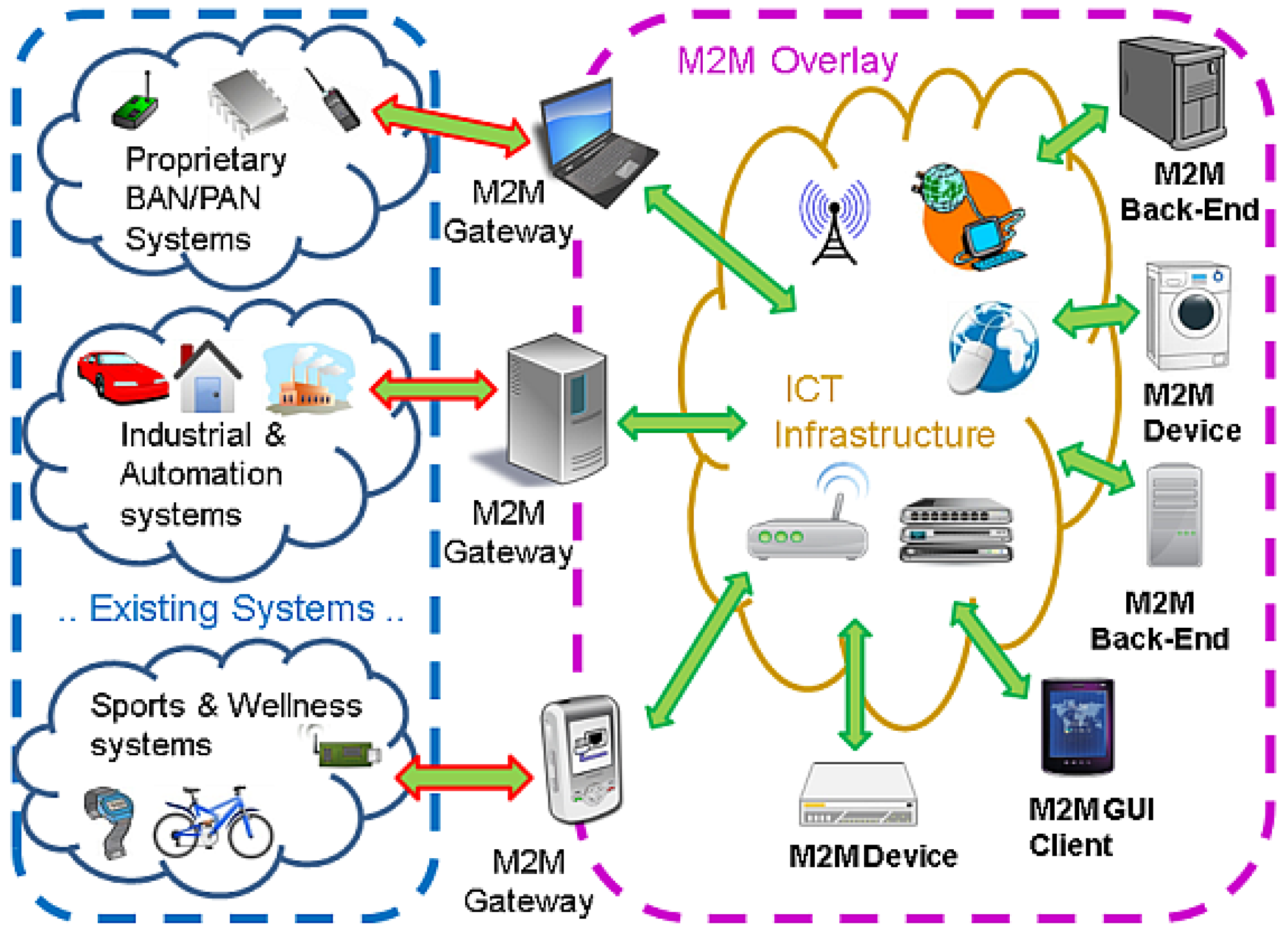
2.2. M2M Gateway for Interoperability

Interoperability with existing systems and resource constrained embedded devices are usually approached via gateways of some sort. For example, the functional architecture designed by ETSI M2M [57], Cisco [58], AnyBridge [59], Systech [60], Alcatel Lucent [61] and IOT-A relies on the use of a kind of M2M gateway mainly because of challenges related to communication with constrained devices. Such a M2M gateway can handle e.g., the issues related to communicating with a system based on an incompatible communication protocol, low-power devices which are unable to communicate with the rest of the system directly due to limited resources or capabilities, or communication with a domain in which the access is otherwise restricted by some service provider. Thus, the gateway can act as a translating and security element, which can interconnect two systems having different protocols and data formats and perhaps belonging to different security domains. Such gateway component may not be optimal from communication point of view, but it is required in some cases because of interoperability and security.
A gateway may also prevent message flooding from devices to the backbone network, enable management of M2M asset devices in groups, make maintenance and configuration smooth, enable usage of unlicensed frequency bands and/or optimized radio technologies for specific M2M asset devices. Typically, a gateway is then connected to a back-end server which is taking care of data storages, management, centralized control and enforcement of security policies. The use of back-end servers have a crucial role in combatting the various scalability and reliability issues found in pure peer-to-peer and ad-hoc -type systems [62,63,64].
The role of the M2M gateway as the enabler of interoperation between different M2M systems such as body area network (BAN)/personal area network (PAN), Industrial and Automation and Sport and Wellness systems is visualized in Figure 2. These different M2M systems can establish their own small (local and/or wide area) M2M ecosystem, which can then be connected with the rest of the system via M2M gateways. The overlay communication between the different M2M gateways, M2M asset devices (those that are not behind the M2M gateways) and back-end servers enables establishment of bigger M2M ecosystem with interoperable messaging enabled by the communication overlay.
Figure 2. The M2M Gateway as an enabler of interoperability.
Futureinternet 06 00261 g002
There are multiple communication options for M2M gateways: M2M gateway as an Internet protocol (IP) router, M2M gateway as a service gateway and direct connection to M2M devices without any M2M gateway. When M2M gateway is acting as an IP router, it makes possible to establish end-to-end IP connectivity if M2M asset devices are supporting IP. In that case, the local radio access technology needs to have mapping to IP communication. If M2M asset devices are not supporting IP, then there is need to have M2M service gateway, which is able to act as a bridge/protocol translator between M2M asset network and M2M infrastructure.
The service capable M2M gateway is able to make protocol adaptation between proprietary protocol stack, and ETSI M2M SCL. Communication with constrained M2M devices can apply any of the options. However, there are several practical challenges which require optimization within the local M2M asset network. The first challenge is related to application of web services within constrained local M2M asset network. To solve this problem, IETF Constrained Restful Environments (CoRE) working group has specified CoAP standard with the goal of supporting REST-like applications inside constrained environments. The second challenge is related to the sizes of IP packets and headers. To solve this problem, IETF has created the 6lowPAN, which describes an adaptation layer between IPv6 and a layer 2 protocol, such as (but not limited to) IEEE 802.15.4, to handle maximum transmission unit (MTU) sizes and compress IPv6 headers from 60 bytes to 7 bytes. The third challenge is related to power consumption of the radio access protocols. For example, Bluetooth special interest group (SIG) has specified special low power Bluetooth (Bluetooth low energy (LE, also called as Bluetooth smart). In addition, IETF is working with mapping of 6LowPan with Bluetooth Smart. There are also challenges arising from heterogeneity and mobility of M2M devices and local M2M asset networks, and coding and integration of M2M application content.

3. Key Building Blocks

The key building blocks: autonomic M2M manager, M2M service capabilities, M2M messaging system, M2M gateways towards energy constrained M2M asset devices and creation of trust to enable end-to-end security for M2M applications are described in this chapter.

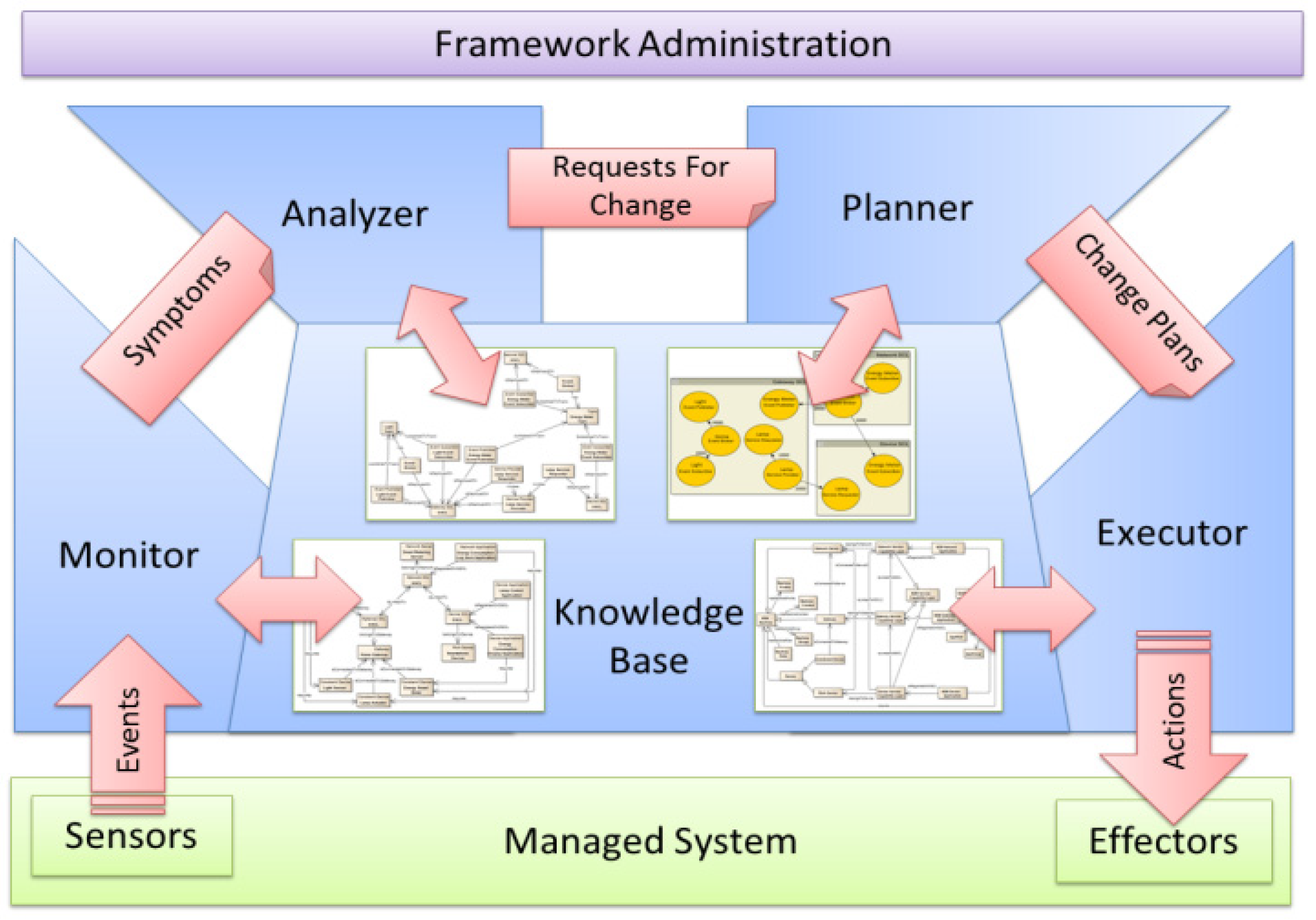
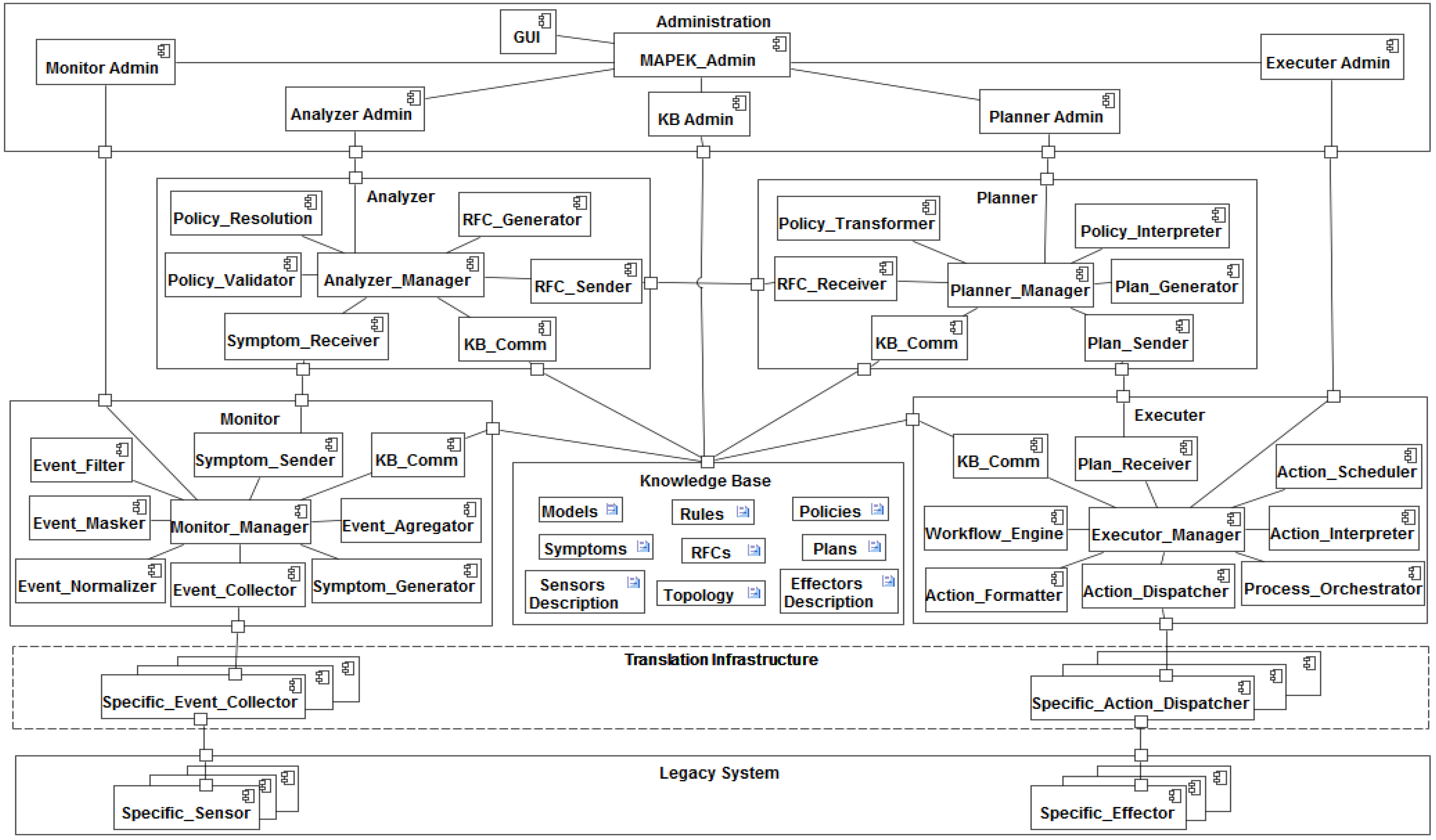
3.1. Autonomic M2M Manager

The autonomic M2M manager is able to monitor the system in information level, analyze the situation, plan the required actions, and execute the control events towards the system automatically or at least semi-automatically, Figure 3. It is a generic and extensible control loop for the self-management of M2M systems [65] based on the IBM MAPE-K control loop model for enabling self-management capabilities such as self-configuring, self-optimizing, self-healing and self-protecting [66]. The control loop operates as an expert system to emulate the decision-making ability of humans and is designed to solve complex problems by reasoning about knowledge.
Figure 3. Autonomic M2M manager.
Futureinternet 06 00261 g003
The control loop consists of modules for monitoring, analyzing, planning and executing, Figure 4. Monitoring module answers to the question “what is happening?” It collects events from sensors from managed resources, updates a model describing the sensors environment and topology located on the knowledge base with relevant information from events, and infers new knowledge about symptom occurrences, then extracts relevant information and sends them to the analyzer.
Analyzing module answers to the question “what to do?” It provides mechanisms that correlate and model complex situation, which mechanisms allow learning about the environment and help predicting changes in the environment. The analyzer receives symptoms as input, uses them to update a knowledge model describing the complex situation. In addition, it generates new knowledge called as RFC, and sends them to the planner.
Figure 4. The component model of the Autonomic M2M Manager [65].
Futureinternet 06 00261 g004
The planner acts as a decision making module, and focuses on the question “how to do?” It saves new knowledge RFCs as goal states, read models of possible actions and facts from the knowledge base and checks policies to guide its work. Then, it selects actions leading to the goal states and sends them to the executor.
The executor receives as input logical description of the sequence of actions to be executed, and consults a model containing actuators description and available operations details. It matches actions with their correspondent concrete operations, then performs the plan using actuators and controls the sequence of actions execution with consideration for dynamic updates. The executor must answer to the question “how is it done?” by generating reports and saving relevant information into the knowledge base.
The knowledge base relies on Web Ontology Language (OWL) [25], which is a semantic an expressive schema language for publishing and sharing ontologies using Resource Description Framework (RDF) extensions. Ontology rules such as the Semantic Web Rule Language (SWRL) [67] provide a way to define behavior in relation to a system.
A translation infrastructure is provided to keep the autonomic manager generic and to facilitate the mapping between the autonomic manager and legacy M2M systems, Figure 4. The administration layer enables to supervise and configure each autonomic module subcomponents for best performance.
An ontology model for M2M is composed of three main classes: M2M_Machine, M2M_Application and M2M_SCL, which enable to represent the most important concepts of the M2M system, Figure 5. An additional class called as Connection is considered to represent potential interactions between M2M applications according to their semantic annotation.
Figure 5. The ontology model of the Autonomic M2M manager [66].
Futureinternet 06 00261 g005
The control loop of autonomic M2M manager is operating in the information level. In addition, it is expected that the ETSI M2M service capabilities are realized as generic components. Therefore, there is need to have means for connecting device management and data interpretation related autonomic service capabilities to connect service capabilities smoothly with autonomic manager and information manager in general. However, it is important to keep the core part of the autonomic M2M manager engines as agnostic as possible towards the M2M information formats, knowledge bases and device management. This is because there are/will be huge amount of different application specific information storages, formats, value representation strategies, metadata structures and ontologies for M2M information. In addition, the device management structures depend strongly on the specific devices, their configuration and related applications.

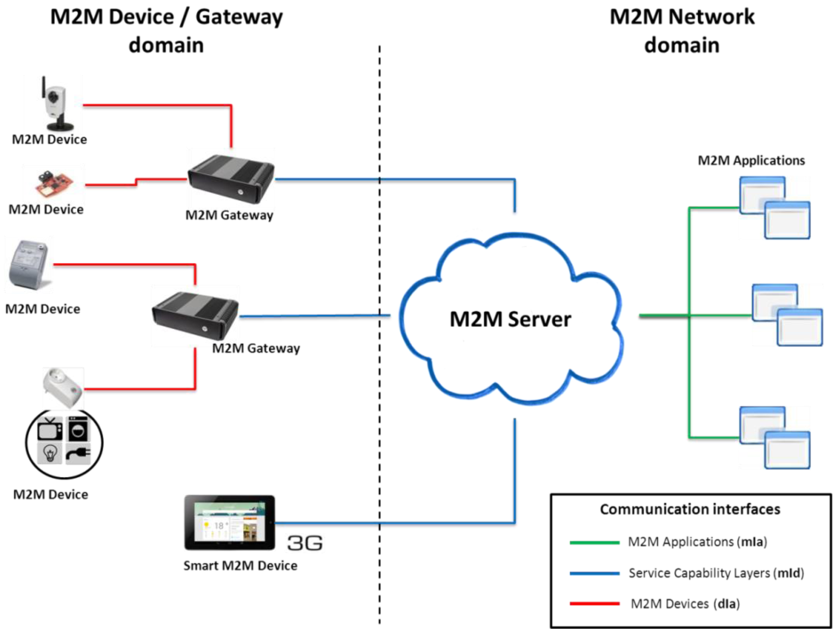
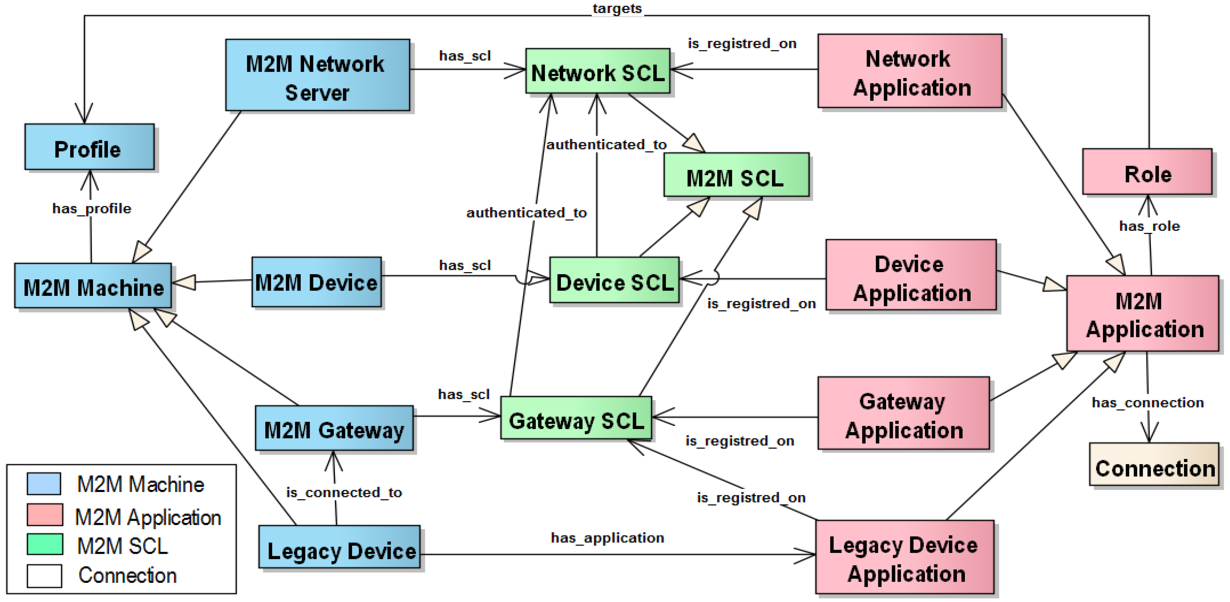
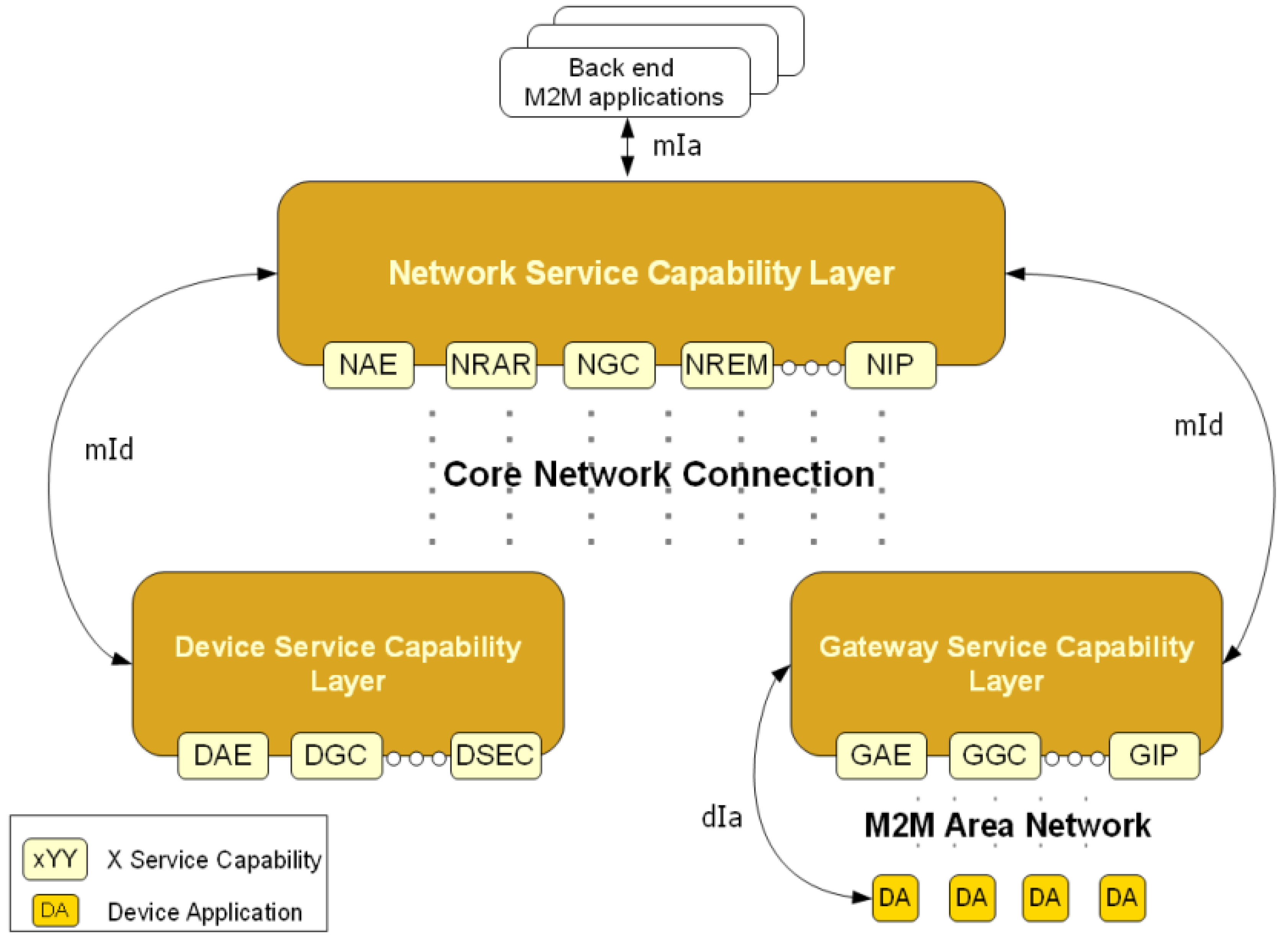
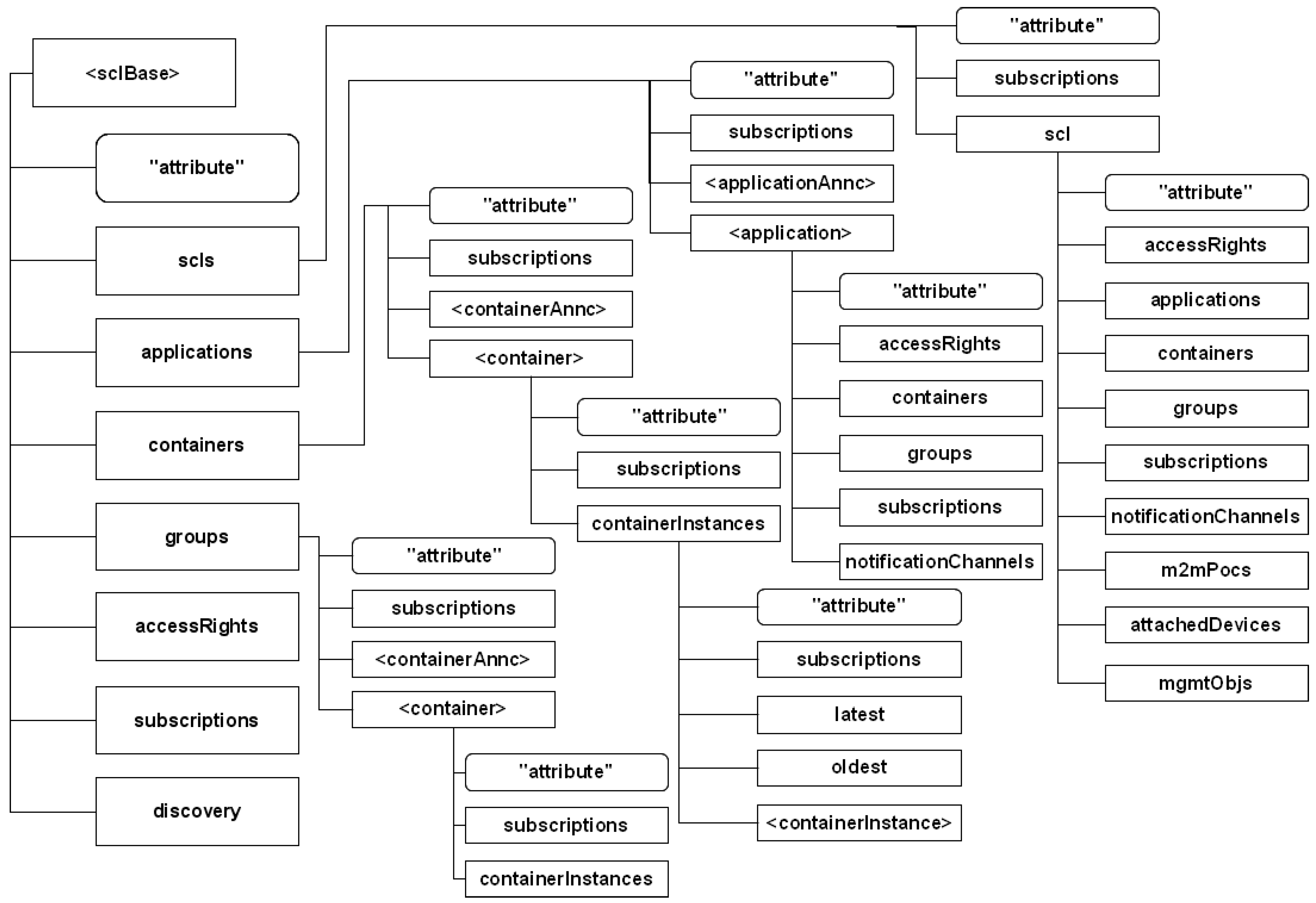
3.2. M2M Service Platform

The ETSI M2M architecture is based on a set of horizontal service capability layers that can be applied to several vertical M2M application domains. These service capability layers are composed of a set of generic services and are deployed in M2M Servers, M2M gateways and smart M2M devices. The different service layers are distinguished by the role they provide in the architecture. Two domains are defined by the ETSI: a local domain with M2M device and gateways called Device and Gateway domain, and a WAN domain with M2M servers, core network access, M2M applications and management functions called Network domain, Figure 6. Data exchange between the different M2M entities in the different domains is done through 3 standardized communication interfaces: dIa, mId and mIa.
  • dIa interfaces devices applications and Gateway or Device Service Capability Layer;
  • mId interfaces the M2M Gateway or Device Service Capability Layer and the M2M Network Service Capability Layer;
  • mIa interfaces backend M2M Applications and the M2M Network Service Capability Layer.
These interfaces aim to be applicable to a wide range of network technology and they are application and access independent [17]. The ETSI has adopted a Restful [68] architecture style for the M2M Applications and/or M2M SCL information exchange [16]. The main advantage of the Restful architecture style is that it’s deployed above the transport layer, so the service capability layer is independent from the underlying networks.
Figure 6. A view to ETSI M2M System.
Futureinternet 06 00261 g006
Each SCL is comprised of several services groups (Figure 7): Application Enablement Capability (AEC) for providing M2M point of contact for using the M2M applications of the corresponding SCL; Generic Communication Capability (GCC) for interfacing between the different SCL available on a given M2M Network; Reachability, Addressing and Repository Capability (RARC) for managing events relative subscriptions and notifications as well as for handling applications registration data and information storage; Communication Selection Capability (CSC) for network selection and alternative communication service selection after a communication failure; Remote Entity Management Capability (REM) for remote provisioning; Security Capability (SECC); History and Data Retention for archiving data (HDR); and Interworking Proxy (IP) for integrating non ETSI compliant systems.
The communication interfaces provided by the ETSI platform allow the following methods: register, deregister, invoke, subscribe and data publish/subscribe. Registered M2M applications/devices can provide their services in two different ways:
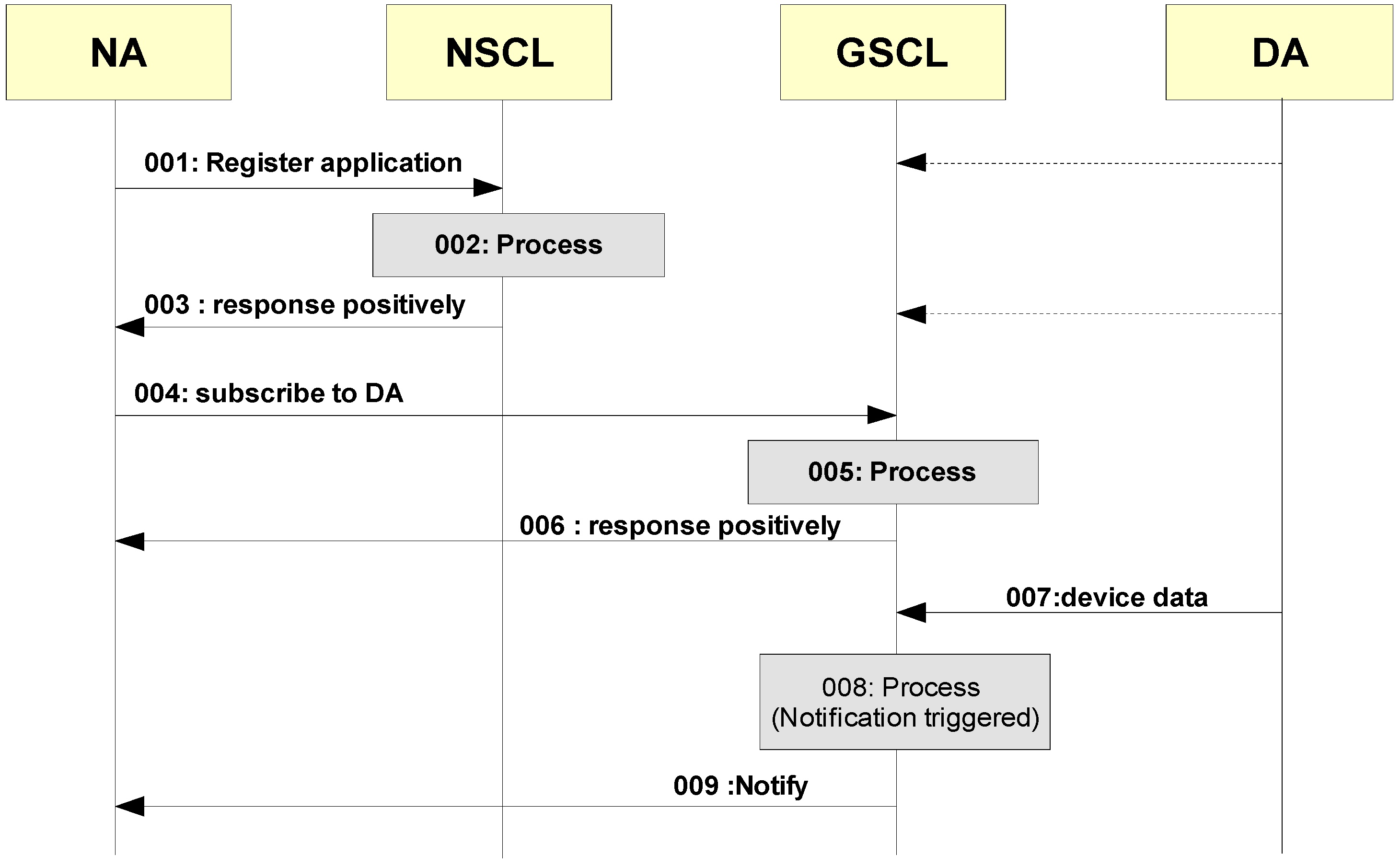
  • Synchronized: Whenever a new value is available, the M2M application shall publish it on the corresponding data resource. This is ideal for a service that only publishes data (a temperature for example);
  • Retargeted: All the operation on the given resource will be retargeted to the corresponding device/application. This is ideal for invocation services such as actuators.
Figure 7. Architecture of ETSI M2M Service Capabilities.
Futureinternet 06 00261 g007
The platform also provides a publish/subscribe mechanism, which can be used to subscribe to data from other applications or to discover other applications (when they register for example). An M2M application can subscribe to one or more ETSI M2M entities. Non-ETSI compliant M2M entities (e.g., existing systems and devices) can be integrated to the architecture using the specified integration points (Interworking Proxy) on the Gateway and Network Service Capability Layers [16]. In the local domain the M2M Gateway acts as a proxy for M2M devices available in the same local area network. Once M2M devices applications are registered, they become available to other registered SCLs and M2M applications; according to the acquired access rights. For example, network applications can subscribe to information produced by a sensor (Device application) registered on a reachable GSCL, Figure 8. We presume that the GSCL is registered to the NSCL and that the Device Application is registered to the GSCL.
Figure 8. Sequence diagram for a network application subscription to device data.
Futureinternet 06 00261 g008
Non-ETSI compliant M2M entities (existing systems and devices) can be integrated to the architecture using the specified integration points (Interworking Proxy) on the Gateway and Network Service Capability Layers [5]. In the local domain the M2M Gateway acts as a proxy for M2M devices available in the same local area network. Once M2M devices applications are registered, they become available to other registered SCLs and M2M applications; according to the acquired access rights. For example, network applications can subscribe to information produced by a sensor (Device application) registered on a reachable GSCL, Figure 8. We presume that the GSCL is registered to the NSCL and that the Device Application is registered to the GSCL. First, the Network application registers to the NSCL (001). Then the Network Application Enablement capability checks if the issuer is authorized to be registered and treats the request (002). The registration information is then stored by the Network Reachability, Addressing and Repository Capability. The Network Application receives a positive answer (003). The Network Application subscribes to the data produced by the desired sensor (Device application) (004). This data can also follow a certain criteria specified by the issue. If the issuer is authorized to subscribe to the given Device Application, the Gateway Reachability, Addressing and Reachability capability treat the request (005). The Network application receives a positive response (006). Device application sends information to the Gateway (007). The Gateway Reachability, Addressing and Repository Capability identify an event that needs to be reported to a subscriber (008). Finally, the GRAR Capability notifies the subscribers (009).
Each element of the ETSI M2M architecture is a resource that can be handled through six functions, the Create, Retrieve, Update, Delete, Notify and Execute. Notify is used for reporting a notification to a subscribed resource. Execute for executing a management command/task which is represented by a resource. An example of ETSI resource tree is visualized in Figure 9. Each part of the tree represents a certain capability of the Service Capability Layer. The notation <resourceName> means a placeholder for an identifier of a resource of a certain type. The actual name of the resource is not predetermined. The notation “attribute” denotes a placeholder for one or more fixed names. The resources without the delimiters < and > or “and”, names appearing in boxes are literals for fixed resource names or attributes. The M2M REST resources can be accessed through URIs (see [5] for more information). M2M REST resources of the tree are mapped to HTTP REST resources and Extensible markup language (XML) data structures. The data types can be mapped to equivalent JavaScript Object Notation (JSON) data structures as well. Each normal HTTP REST resource shall have a representation in XML. One M2M resource corresponds to one XML or JSON data structure. The resource representation shall be carried in create requests (POST), update requests (PUT), successful retrieve (GET) responses and notify (POST) requests. When transported in a HTTP request or HTTP response, the resource representation shall be carried in the body.
Figure 9. An example Service Capability Layer (SCL) resource tree.
Futureinternet 06 00261 g009
ETSI M2M SCL has been specified to enable generic horizontal service capability layer to be applicable for multiple applications. It assumes that M2M applications know all the details of the device installation and data interpretation. This is challenging for M2M application developers, and therefore, autonomic service capabilities for Device Autonomic Capability, Gateway Autonomic capability, Network autonomic capability are being created for SCL, to connect it smoothly with autonomic manager and information management. .

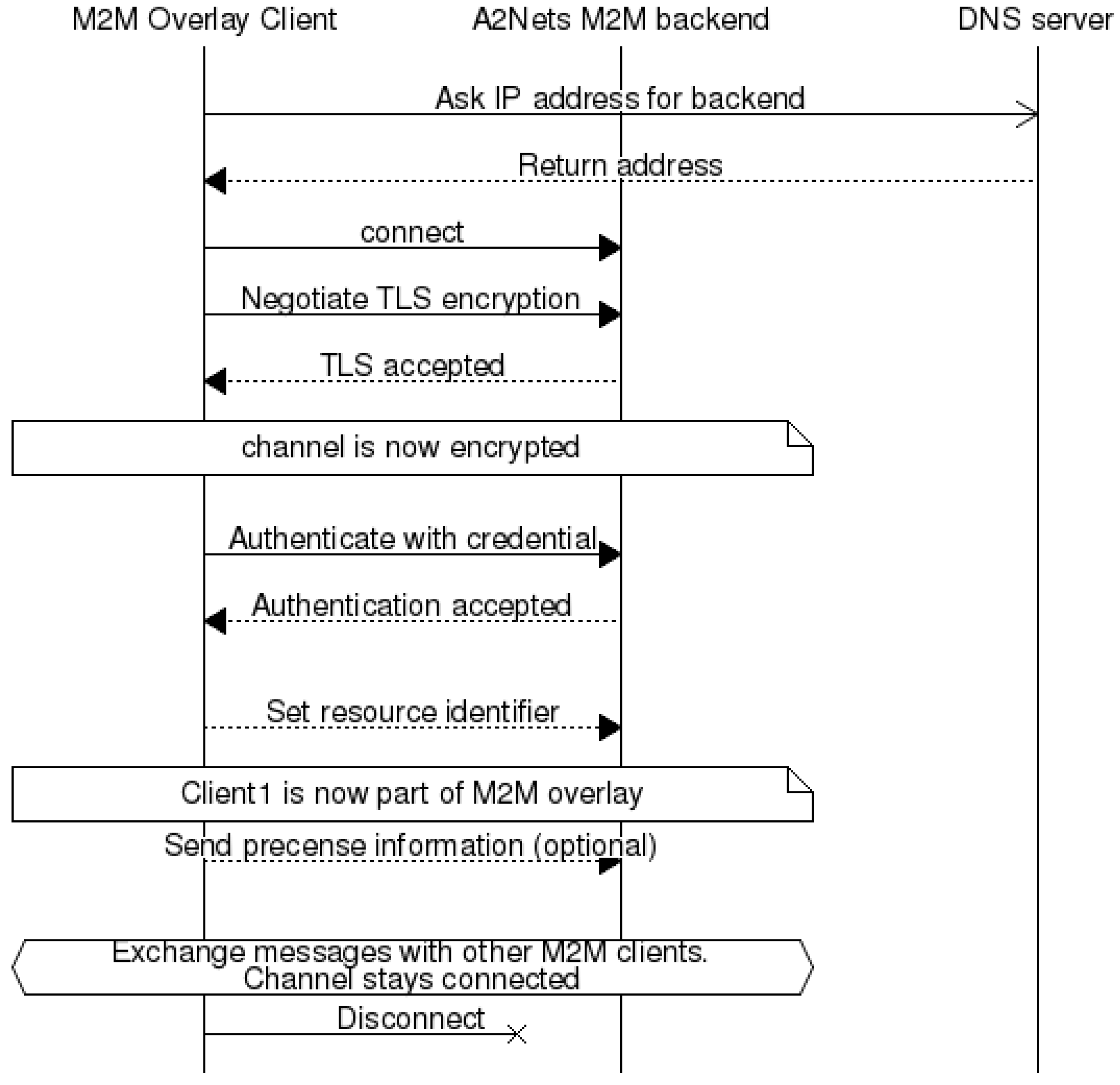
3.3. M2M Communication Overlay

XMPP (Jabber has been developed to enable message oriented communication services applicable in the Internet context. It is an open standard based communication protocol for message-oriented middleware based on XML, which is executed on top of standard Internet TCP/IP protocols. An important feature of XMPP is smooth extensibility, which is seen by the big number of extensions defined by XMPP Standards Foundation (XSF) in XMPP extension XEPs.
The XMPP communication architecture is based on distributed client-server model; however, also server-to-server communication is enabled. The core services of XMPP includes support for presence information, secure messaging (TLS), overlay communication over IP, near real-time messaging, authentication, contact list management, and service discovery. Each XMPP client has an account hosted by a XMPP server, and the client can be addressed by unique Jabber ID (JID). XMPP JID contains three parts: user, domain and resource as shown in Table 1, RFC 6122. In XMPP, network domain-part of JID must be a fully qualified domain name or IP address. Each domain presents one logical groups with one user account database. Each domain may present own user account policies. The device owner is usually considered to be also a user of the M2M domain and an owner of at least one XMPP user id. All devices share same user id (local-part and domain-part) with their owner. Separation of devices is done by examining the resource part of JID.
Table 1. An example of Extensible Messaging and Presence Protocol Jabber ID (XMPP JID).
JID: [email protected]/device12
Local-partDomain-partResource
Johnexample.comdevice12
A client connects to the server to send and receive messages. The procedure for M2M client establishing connection with the XMPP server is shown in Figure 10. Discovery can be done directly using a domain part as a server address or discovering server address with SRV lookup from DNS. All clients connect to only their own server specified by JID. Connections are persistent XML streams over TCP and optionally encrypted by Transport Layer Security (TLS) layer. Encryption of TCP stream is strongly recommended, but not required. An administrator of a domain may specify that encryption is mandatory and it is up to administrator or designer to choose whether TLS certificates should be checked. Most client libraries accepts self-signed certificates, this should be taken into account when considering security aspects of client-to-server connections. The availability of each client can be detected with the aid of presence messages. Presence information is shared only with XMPP user’s that are in roster/address book of client sending the presence information.
Server to server connection is an XML stream over a TCP connection, similar as to client to server connections. Most important difference is that server to server connections are not authenticated because they happen in between different domains that do not share a common user database. This is similar to how email systems work. XMPP servers may use XMPP Dial back, as defined in XEP-0220, to verify the domain of the connecting server. The domain administrator may require stronger identification verification by using TLS certificates and Simple Authentication and Security Layer (SASL). When M2M clients located in different domains would like to exchange messages, routing of messages will be done by the domain specific servers, Figure 11. Then communication link between servers of the domains are negotiated, to enable messaging between the referred M2M clients.
Figure 10. M2M client connecting to XMPP Server.
Futureinternet 06 00261 g010
In practical M2M cases, several extensions XEPs to XMPP have proved to be useful. XMPP Service discovery is used in M2M system for discovering information about clients, servers and publish-subscribe nodes (XEP-0030). XMPP Publish subscribe valuable as base for one-to-many data delivery scenarios in M2M (XEP-0060), which can be used by XMPP entities to subscribe information of the presence of other entities, and receive notifications accordingly. Publish-subscribe support provides also base for Sensor-over-XMPP functionality, which defines basic metadata for M2M devices to describe their sensors and actuators [69]. Sensor-over-XMPP also defines sensor data formats and commands for actuating devices. In publish-subscribe system the interested parties can subscribe the data they are interested in, and subscribers receive the data only when changes occur. A very important extension to XMPP is support for including XML-data (XEP-0315) in data forms specified in XEP-0004. This is estimated to enable transfer of application specific M2M information via XMPP based M2M communication overlay in such a format that it can be applied by autonomic M2M manager. It can be applied in such a way that first, an XML information event is created within M2M asset device. Then it is transferred via XMPP overlay using the XML data forms solution, XMPP interworking proxy concept realization towards ETSI M2M SCL (GIP in Figure 7), and autonomic service capability solution to transfer the event into the autonomic M2M manager. Autonomic M2M manager analyses the content of the event against situation and automatically creates the required response action, based on available rules stored in the knowledge base. After it, the created action will be transferred over the network back to the M2M asset device. When applying the architectural principles, the communication over the XMPP, interworking proxy, and autonomic service capability are transparent to the applications specific information. This enables creation of novel application logic by making changes only into the application domain specific part of the system.
Figure 11. Server to server interdomain communication.
Futureinternet 06 00261 g011

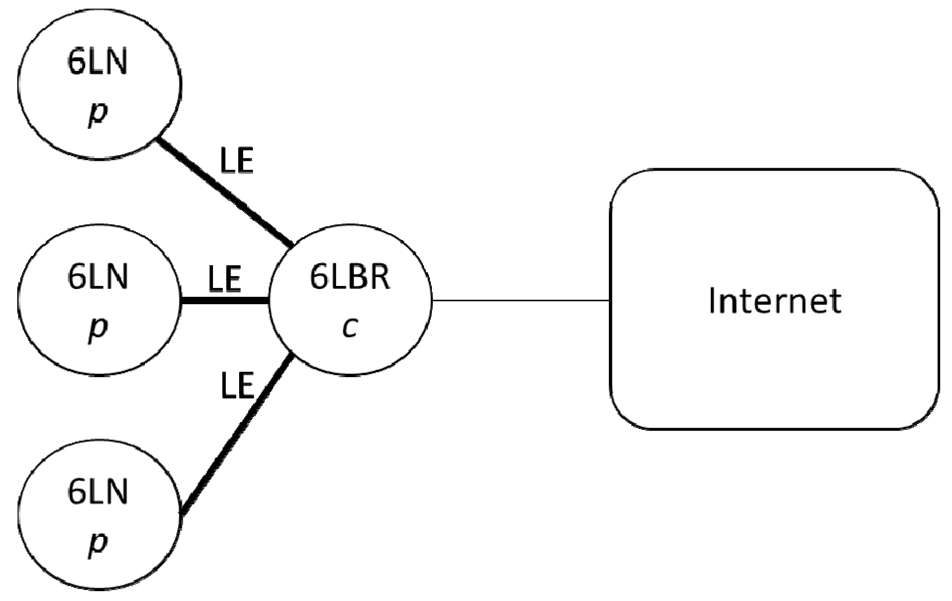
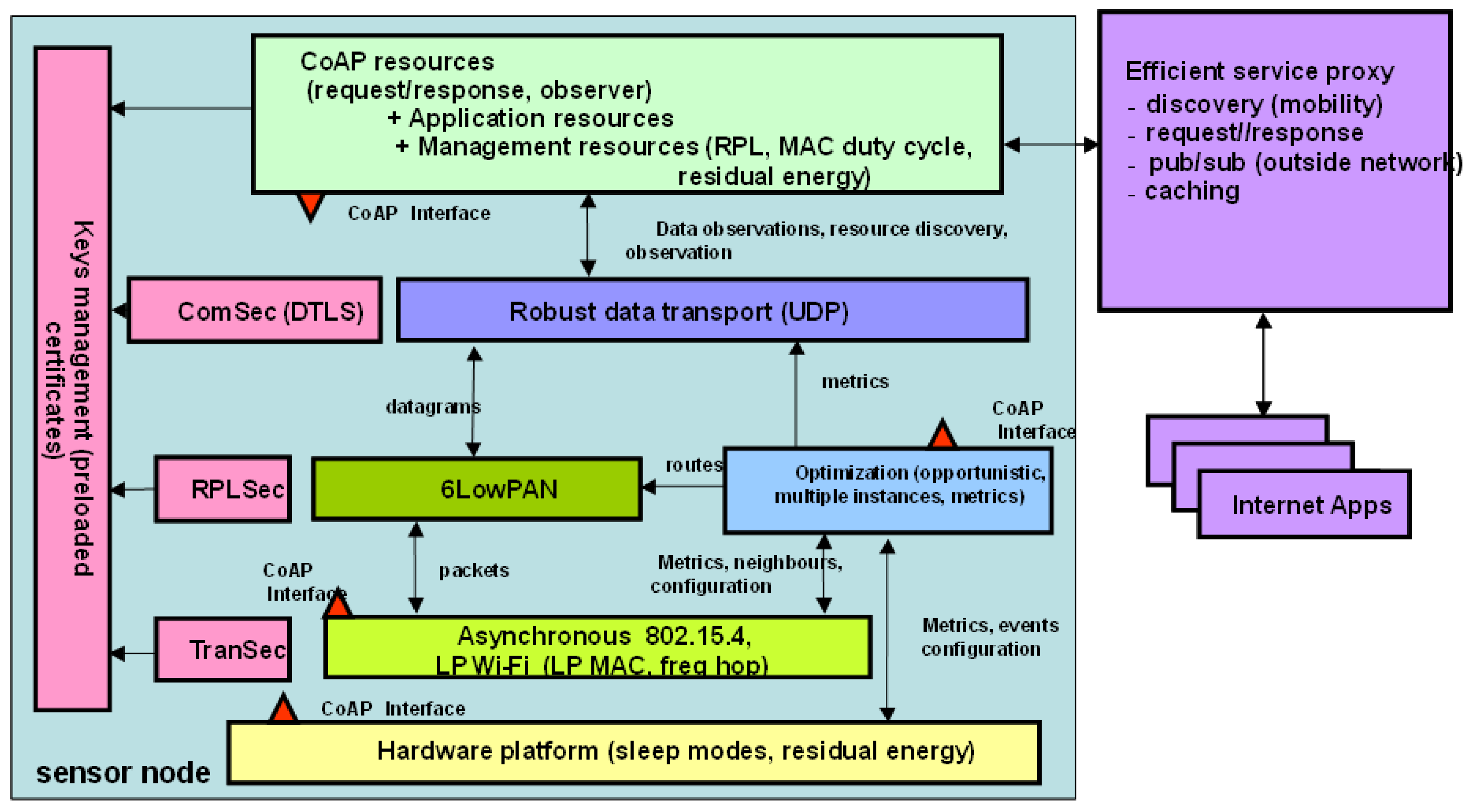
3.4. M2M Gateway with Constrained Devices

Communication with embedded M2M asset devices requires usually protocol conversions and special router/gateway arrangements, because of limited power sources in devices. For example, conversion of HTTP to/from CoAP, conversion of XMPP message content to be transferred via Bluetooth Smart, and conversion of IPv6 messages to 6LowPan, and 6LowPan to Bluetooth Smart.
The IETF CoRE working group [7] has defined the CoAP standard with the goal of supporting REST-like applications inside constrained environments. It defines a binary message structure between CoAP endpoints as well the interaction protocol. By following REST architectural principles [68], CoAP exposes a representation of the information available on a constrained device as a set of identifiable resources. This way, any CoAP endpoint may interact with it remotely using the interaction methods used by the HTTP protocol: GET, POST, PUT, and DELETE. In order to make the resources discoverable, the CoAP protocol standard advises to expose CoAP endpoint’s resource metadata using the CoRE Link Format [8] at a specific Uniform Resource Identifier (URI). UDP will be used instead of TCP, because TCP is inefficient in terms of network resource usage in wireless environment. In order to meet eventual Quality of Service (QoS) requirements, CoAP has introduced the use of confirmation messages, which correspond to an acknowledgement that a CoAP message has been received.
Collection of data from a CoAP-enabled device is achieved by sending a CoAP request message (GET method) to the CoAP server hosted on the device: as soon as the CoAP server receives such a request, it replies with a CoAP response with data requested by the CoAP client or notifies that the response will be sent in a separate response. Another interaction scheme supported by the CoAP protocol is the publish/subscribe paradigm. Instead of sending periodical requests to a CoAP server to be kept updated on the status of a resource, the CoAP client may subscribe, through specific exposed end-points, to a CoAP server, which will be in charge of periodical updating all the subscribed clients of the status of a given resource.
Restful architectures make caching of the data possible within the network. Caching is supported by CoAP and makes it possible to optimize the data delivery over potentially constrained wireless links. For each CoAP observed value a lifetime is defined; if two consecutive requests are received by a CoAP server or proxy in a period of time smaller than that defined by the lifetime parameter, the former request will be sent querying the resource, whereas the latter will be served using the cached value. Using caching, some optimizations can be easily foreseeable for M2M communications. By serving fresh information from a cache instead of querying the endpoint itself, one could experience a shorter delay or a better QoS on a particular request. Also, caching may help reducing the overall consumption of an energy-constrained network by reducing the number of wireless transmissions required for collecting data.
CoAP has been designed for low-power networks and is not applicable for wide-area networks, which mostly rely on HTTP for distributed application. HC (HTTP/CoAP) proxies provides the interworking functionalities for application spanning across low-power networks (potentially running CoAP/UDP/IPv6/IEEE 802.15.4 protocol stack) and the Internet (HTTP/TCP/IPv6). CoAP base specifications identify DTLS [11] and IPsec [12] as mechanisms to offer data origin authentication, integrity and replay protection, and encryption for the CoAP messages. In addition to these, an alternative [13] to IPsec and DTLS has been presented.
IPv6 brings some outstanding benefits such as an addressing scheme which allows identifying billions of devices and the support for point-to-point communications between a device and a PC connected to Internet. However, the IPv6 protocol is inadequate for low power wireless networks because of high overhead. As a consequence, the IETF 6LowPAN WG [14] has proposed adaptations of the IPv6 protocol for constrained wireless networks. For example, standards have been proposed for the transmission of compressed IPv6 packets over IEEE 802.15.4 networks [15]. IPv6 and 6LowPAN network stacks are natively available on common operating systems for embedded devices (e.g., Contiki and TinyOS), therefore making them able to communicate with both Internet and LLNs devices.
Another aspect of low power networks is the strong constraints on routing protocols, which must be different from those used in traditional IP networks. First of all, links conditions may change frequently during time, therefore a routing protocol must react quickly to these changes. Second, the nodes have really strong storage constraints; therefore a routing protocol should work even if a node has not stored all the routes to each other node in the network. Third, since the nodes have severe energy constraints, the exchange of control messages should be kept as low as possible. One solution is provided by the RPL routing protocol. It has been developed to have really limited control traffic, to fit harsh and constrained environments, with limited data rate and potentially elevated error rate. RPL is a distance-vector protocol based on the creation of a routing tree, referred to as Destination Oriented Acyclic Directed Graph (DODAG), where the cost of each path is evaluated according the metrics defined in an objective function. The goal of this protocol is the creation of a collection tree protocol, as well as a point-to-multipoint network from the root of the network to the devices.
Communication with constrained M2M asset devices has been enabled by energy efficient proxy including CoAP, RPL and 6LowPAN, Figure 12. CoAP standard is applied to support REST-style applications in constrained environments. 6lowpan is applied with IEEE 802.15.4, to handle MTU sizes and compress IPv6 headers from 60 bytes to 7 bytes. RPL routing protocol is applied to limit the required control traffic, to enable routing in harsh and constrained environment with limited data rate and low error rate. The proxy component is needed to handle heterogeneity of M2M devices and local M2M asset networks, data delivery over constrained wireless links and interworking functionalities for application messages between local M2M asset network and Internet with ETSI M2M SCL.
Figure 12. M2M communication proxy for energy efficiency.
Futureinternet 06 00261 g012
The proxy can be applied to optimize M2M communications, and it is needed also to enable interworking with ETSI M2M SCL via gateway interworking proxy (GIP), Figure 7. By serving fresh information from a cache instead of querying the endpoint itself, one could experience a shorter delay or a better QoS on a particular request. Also, caching may help reducing the overall consumption of energy-constrained network by reducing the number of wireless transmissions required for collecting data.
In the example case, the CoAP, IPv6 and 6LowPAN network stacks on Contiki platform has been applied [70]. The implementation leverages the ContikiMAC low-power duty cycling mechanism to provide power efficiency. Based on the results of the CoAP request/response cycles are most energy-efficient when each message fits into a single 802.15.4 frame. When messages are bigger than frames, the interoperation of information models, data encoding/decoding, and segmentation/reassembly with constrained M2M capillary networks and M2M asset devices need to be carefully considered together with proxy. In the evaluation environment, it is seen that smart decisions related to querying are able to optimize energy consumption i.e. whether to use cached value or to query over the network. In addition, if several routes are available, smart decisions can be done to minimize energy consumption.

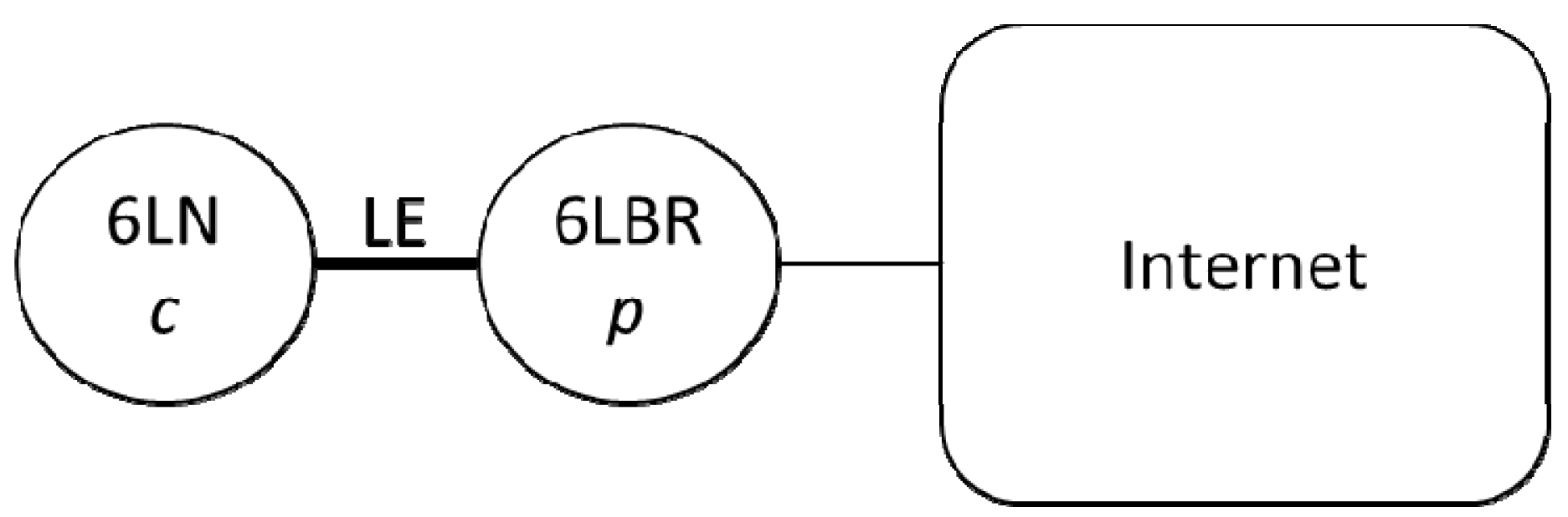
3.5. IPv6 over Bluetooth Smart

Bluetooth SMART v. 4.1 [8,71] is a PAN technology that was introduced to the market by the Bluetooth SIG in 2013. Bluetooth SMART consists of two distinctly different transports called Basic and Enhanced data rate (BR/EDR, collectively named Classic) and Low energy (LE or Smart). Smart supports 2 modes of connection: Non-connected, unidirectional advertisements (broadcast, unicast and scan support); Connected, bidirectional and reliable (maximum theoretical application throughput is 300 kbit/s).
The network topology for connection is scatter net where the collector device is typically a master and sensors are slaves. Bluetooth uses 3 channels for service advertisements and 37 channels for data. One reason for having the master role assigned to the collector is that collocation of multiple radios in a mobile handset requires time sharing between radios. The Bluetooth co-existence controller is specified in Core specification 4.1 is particularly important in combination with 4G networks as LTE TDD that occupies a frequency directly adjacent to Bluetooth. LE also improves robustness and co-existence with nearby networks by using adaptive frequency hopping.
Bluetooth is a hierarchal stack consisting of the following layers and functional units:
  • Radio and link layer (LL) with an AES-128 bit encryption unit;
  • Multiplexer. Logical link control and adaption layer protocol (L2CAP) providing fixed and connection oriented channels together with fragmentation and reassembly (FAR);
  • Security Manager (SM);
  • Host Controller Interface (HCI). Connects application processor and Bluetooth controller;
  • The General Access profile (GAP). Contains a collection of standard procedures;
  • Generic attribute profile (GATT) provides an interoperable framework with service discovery and operation. Bluetooth SIG defined service data is characterized by 16 bit universally unique identifiers (uuids) while proprietary extensions use randomized 128 uuids.
The Bluetooth protocol multiplexor (L2CAP) can be used to add new transport protocols to the Bluetooth SMART stack. L2CAP is a symmetric protocol which implies that any device can create a bidirectional channel to receive or transmit data. A significant constraint on the multiplexor in Bluetooth 4.0 was the limited MTU. As part of Bluetooth 4.1 the multiplexor has added support for connection oriented channels with credit based flow control that allows for exchanging large data packets with MTU up to 64 kBytes. Bluetooth Smart is intended for very memory constrained devices and flow control was considered essential. To receive data on device has to give the other device credits that indicate the amount of data that can be received. The mechanism supports the full process of segmentation-reassembly (SAR) and fragmentation-recombination and (FAR). Other traffic can be scheduled around segments implying that with well selected parameters a system will not hang due to a long data transfers; rather multiple service traffic can coexist on one radio interface.
The architecture of the IP solution will now be shortly described. The IP solution is using Bluetooth merely for two purposes, discovery and transport. Bluetooth is used to either advertise an IP service to other devices/service or finding the service through GATT and as a transport for IP datagrams. Bluetooth 4.1 supports scatter nets, but the most common used topology will be a star where sensors are Peripherals or slaves and e.g., a phone is a Central master, see Figure 13. The architecture can support an IP mesh in the future although the first specification is not expected to allow mesh. The topologie and roles in Bluetooth LE pico net are represented in Figure 13. Sensors are 6LoWPAN nodes (6LN) and the central is a 6LoWPAN Border Router (6LBR), which connects the Pico net into the Internet.
Another topology that may be important is when a central device connects to e.g., a sensor device that advertises a primary Bluetooth service that is not related to IPV6 at all but the sensor supports Internet connectivity, Figure 14. The Central device may still discover that the device supports Internet connectivity by finding the IP Service using GATT service discovery.
One proposed option for the M2M communication is an end-to-end Internet based approach. To enable such end-to-end connectivity also for Bluetooth LE devices, details of IPv6 transmission over Bluetooth LE have been specified in [71]. One of the presented mechanisms of the draft is adapting certain functionalities of 6LoWPAN [14] to Bluetooth LE.
Figure 13. The topology of Bluetooth LE Pico net with roles.
Futureinternet 06 00261 g013
Figure 14. Central device connects to a sensor and discovers an embedded Internet services that was not advertised. The 6LBR may accept connections from many 6LNs.
Futureinternet 06 00261 g014

3.6. M2M Security

The M2M service platform may be privately owned for operation in a closed ecosystem, but it may also be operated by a third party business entity: the “M2M service provider”. Security in such a platform is quite an important issue and typically encompasses two phases: In the first initial secrets are exchanged during an enrolment (or security bootstrap) operation between parties needing to communicate privately. In the second phase, those secrets are actually used to control resource access and secure data communications.
In the case of the ETSI M2M platform those two aspects are being considered and the ETSI M2M security framework addresses the definition of M2M service bootstrap and M2M service connection procedures. It supports mutual authentication, integrity protection, and confidentiality on M2M Device or M2M Gateway-to-Network Interface. Several security bootstrapping methods are supported by the specification, including PKI based methods and techniques relying on the presence of 3GPP network elements typically deployed by Mobile network operators (MNO) such as GBA and SIM/AKA. However little support is provided for security bootstrap when using small and constrained M2M objects such as sensors.
The security model currently proposed by ETSI M2M architecture is a piecewise security model: The data sent between a source device and a recipient application via the M2M service platform are protected from the device to the M2M platform and from the M2M service platform to the destination using different credentials controlled by the M2M service provider as shown on Figure 15. As a consequence, the data are always available in clear at the level of the M2M service platform. This may be a problem when the platform is operated by an M2M service provider which is not involved in dealing with the semantics of the data transmitted. For example, an M2M service provider may carry data originating from health body sensors and simply route this data to the processing center for interpretation. Trust may then be the issue for this type of confidential data. If the platform is privately operated, then having the data available in clear at the level of the platform may require putting in place security measures to minimize the risk of data compromising, thus increasing the operating cost. In both cases, an end-to-end data protection scheme would constitute a better solution.
Figure 15. ETSI M2M Trust model.
Futureinternet 06 00261 g015
Our security contribution is related to the definition of security architecture suitable to achieve end to end data protection and compatible with the ETSI M2M platform architecture. The main concept of the novel architecture is to unbundle the functionality offered by the service platform and separate from it the trust related functions which will be implemented into a separate platform built around an Oauth authorization server, Figure 16.
The architecture shown on Figure 16 involves 4 actors:
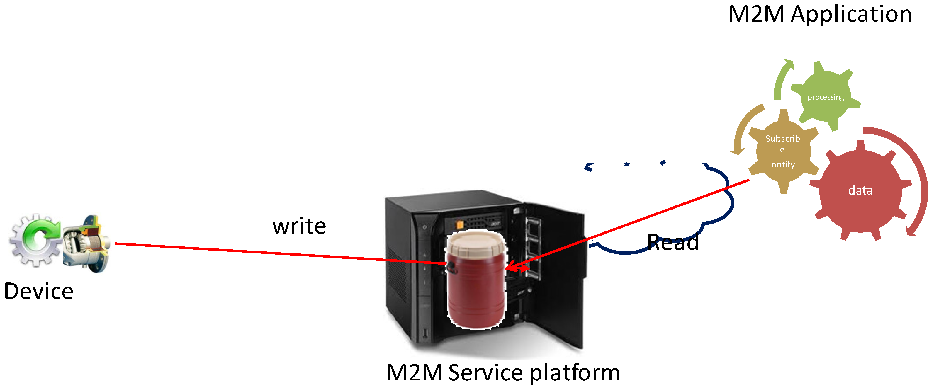
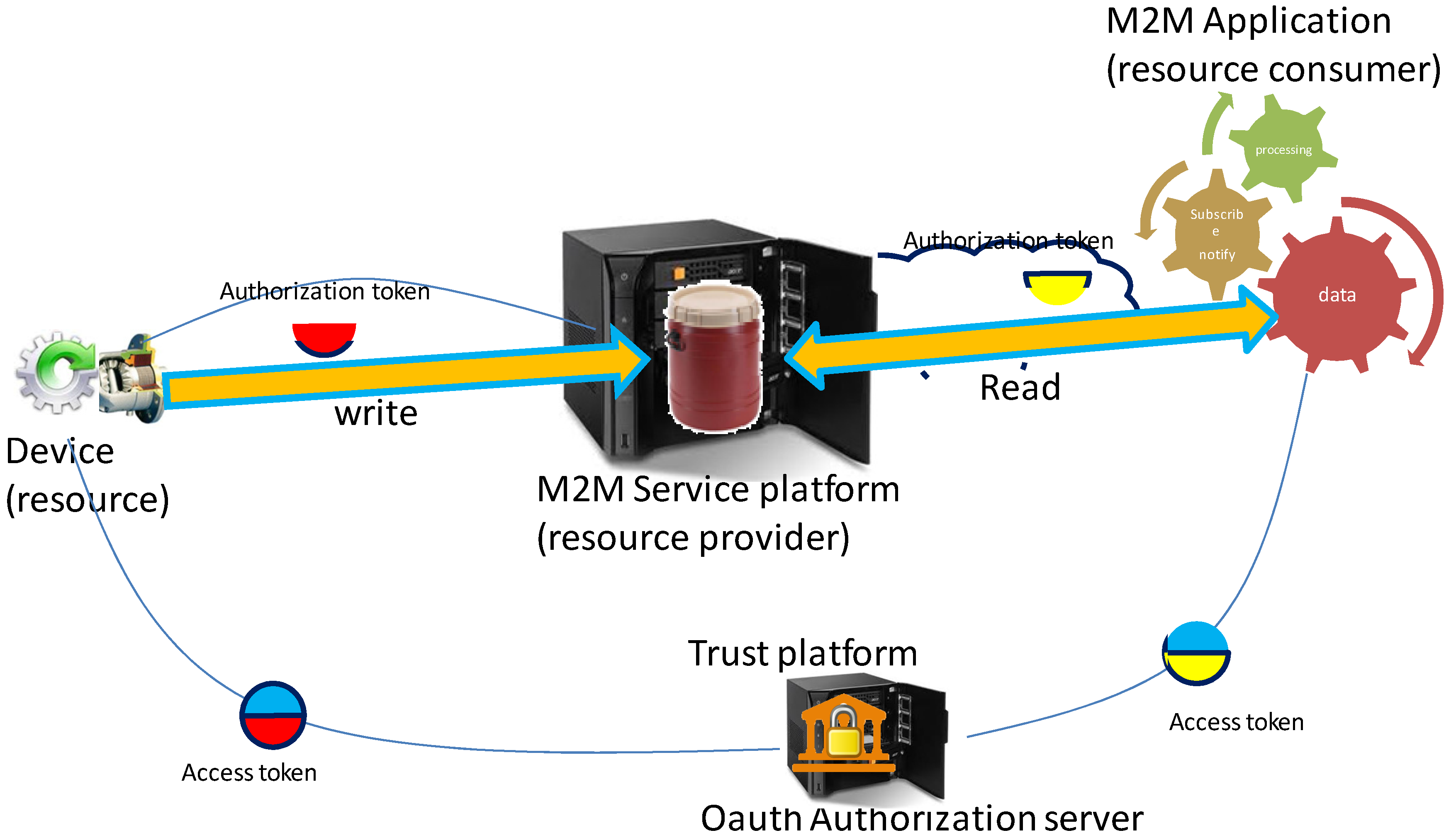
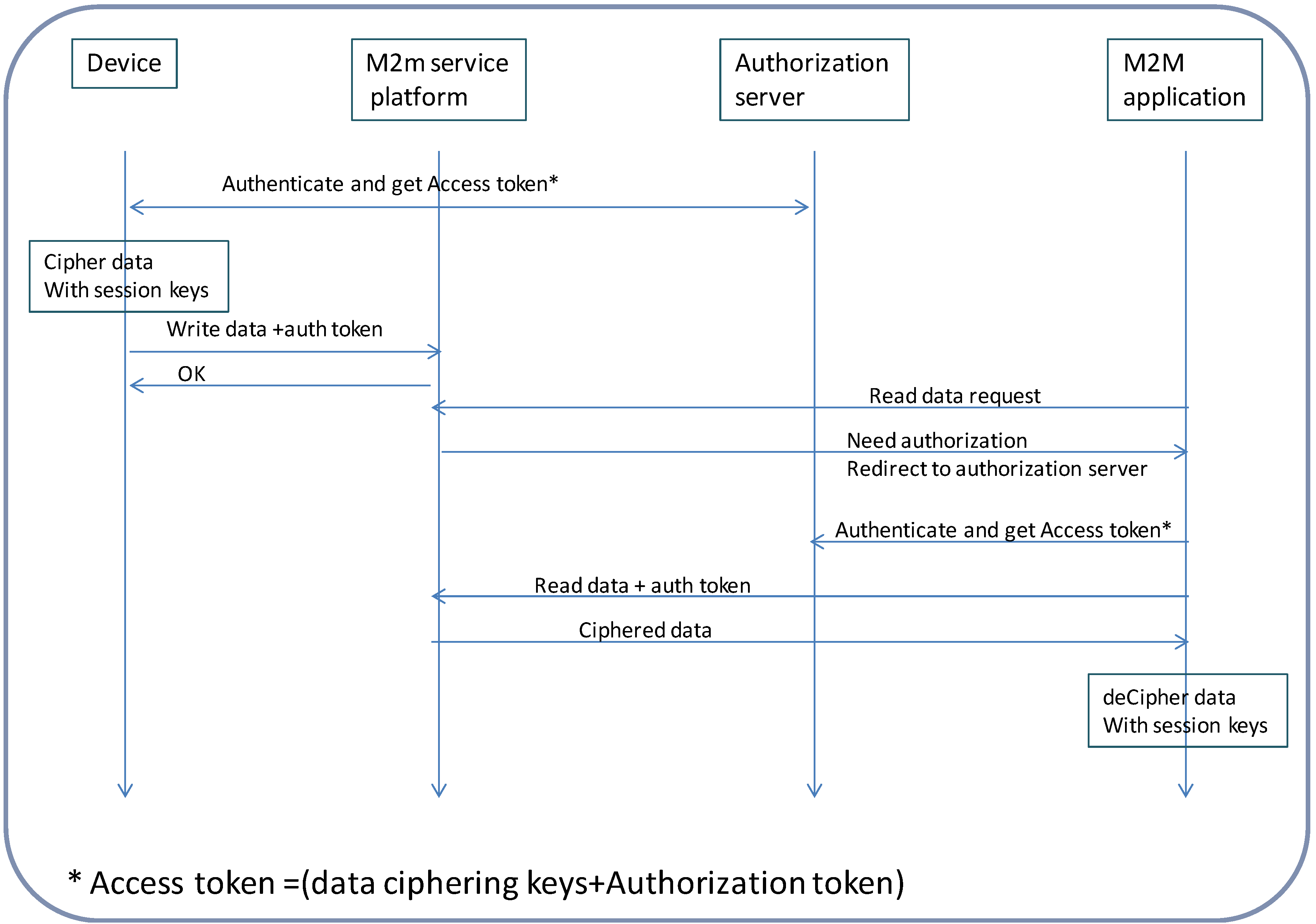
  • The device, exposed here as the “resource” is assumed in this discussion to act as a data generator, i.e., a sensor);
  • The M2M application requiring access to the data sent by the device. The M2M application will act as a “resource consumer”;
  • The M2M service platform enabling the application to read data sent by the device, acts as a “resource provider”;
  • The authorization server implementing the Oauth authorization protocol holds the data access right policies for the device and implements the decision process based upon those policies. The authorization server is a Policy decision point.
Figure 16. Achieving End-to-End security for M2M communications.
Futureinternet 06 00261 g016
Sending data from the device to the M2M application via the service platform will be achieved via the use of a data container located in the platform. Read/write access to this container will also be managed by the platform based upon authorization decisions made by the authorization server. The M2M service platform will enforce policy decisions made by the authorization server acting therefore as a Policy Enforcement point.
In a first step and ahead of any data exchange, an initial enrolment procedure takes place. The owner of the device registers the device with the service platform and with the authorization server and also defines read/write access rights policies to this device. In this phase the owner of the device typically grants read access to the device to the M2M application. This enrolment phase results in the distribution of long term credentials (typical expressed in months or years) for the device and the M2M application making possible for them to authenticate with the authorization server.
When opening a data session the long term credentials are used both by the device and the M2M application to create shorter lifetime credentials used to actually protect data communications during the session time which can typically extend from a few hours to a few weeks. The device, after authenticating with the Authorization server will obtain a digital access token bundling together two distinct credentials:
  • Session encryption keys for private consumption used to cipher/decipher sent/received data( in our scenario, the data sent);
  • Signed authorization token for public usage to be presented to the M2M service platform along with a data write request.
The M2M application, after authenticating with the Authorization server will obtain a similar access token; It will use the Session encryption keys used to cipher/decipher the data sent/received from the device (in our scenario the data received), and will present the authorization token to the M2M service platform in order to gain read access to the container holding the data sent from the device. The flow of operations involved in a typical write/read operation is shown in Figure 17.
Figure 17. Flow of operations when transferring data from device to application.
Futureinternet 06 00261 g017
The M2M Application first issues an initial unsuccessful read request to the M2M service platform and is subsequently redirected towards the authorization server to authenticate and obtain an access token. This token will contain the same data ciphering keys as the one delivered to the device. It will also contain an authorization token to present to the M2M service platform in order to gain read access to the device data.
It should be noted that the ciphering keys are kept private both by the device and the M2M application. This opens the possibility to achieve end to end data protection between the device and the M2M service platform and to benefit from the data distribution services of the M2M service platform without having the data available in clear at the level of the platform. It may happen however that some of the services offered by the M2M service platform require access to the data in clear. Semantic analysis or context awareness is example of such services. In this case, the platform acting as an M2M application, will be registered as a valid data recipient by the device owner, and will obtain the session keys needed to cipher/decipher the device data. Now, M2M applications often involve the need for one to many communication schemes. For example, the data originating from one device may need to be transmitted to several receiving applications, possibly using a publish/subscribe mechanism. The security architecture described here is perfectly suited to support this type of communication. The ciphering/deciphering keys distributed by the Authorization server are in fact group keys to be distributed to all parties involved in the communication scheme.

4. Evaluation

The evaluation of the key enablers has been carried out in three experimental application cases: electric bike, smart metering and car sharing. The autonomic manager, service capability layer and CoAP based communication with low power networks has been evaluated in the smart metering case. The XMPP based communication overlay and Bluetooth smart connectivity has been evaluated in the electric Bike system case. XML based information exchange and M2M Gateway concept has been evaluated in car sharing case.

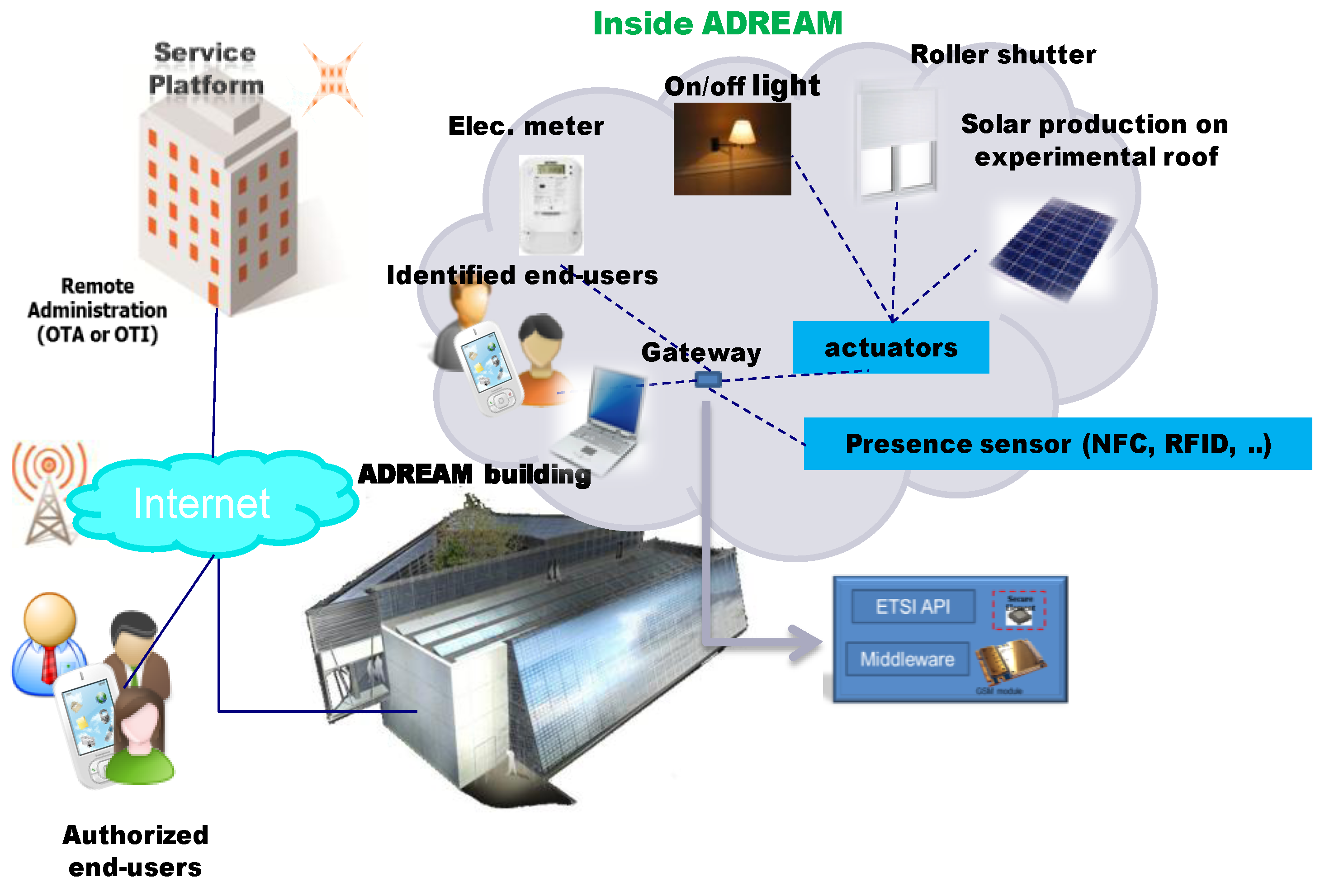
4.1. Smart Metering Experiment

4.1.1. Smart Metering Case Description

The smart metering case has been overviewed in Figure 18.
Figure 18. Smart metering case.
Futureinternet 06 00261 g018
The system has been built around the ADREAM building, and its’ main purpose is related to improvement of energy efficiency. The main components in the smart metering system are pointed out and visualized in the Figure 19. The novel prototyped components are autonomic M2M manager, ETSI M2M service capability layer with autonomic service capabilities; CoAP based communication with local low power network.
Figure 19. The main components of the smart metering system.
Futureinternet 06 00261 g019

4.1.2. Evaluation Results

The main evaluation results are shortly overviewed in the following:
  • The detailed evaluation results of the autonomic M2M manager as a component have been presented in [65], and shortly summarized in the following. The basic mechanism relying on the IBM MAPE-K control loop model seem to work fine in the smart metering use case, however, there are still challenges related to scalability and performance;
  • When considering the semantics of the data conveyed by M2M applications, ETSI has now become a part of the new ONEM2M consortium that intends to address the semantic description of M2M data. However, this is a large task that is very challenging to be handled by a single standardization, body because of multiple application domain specific views to the referred M2M data. Therefore, it is better to apply application domain specific models for the semantics of M2M application data and not to include it into the horizontal service capability layer specifications;
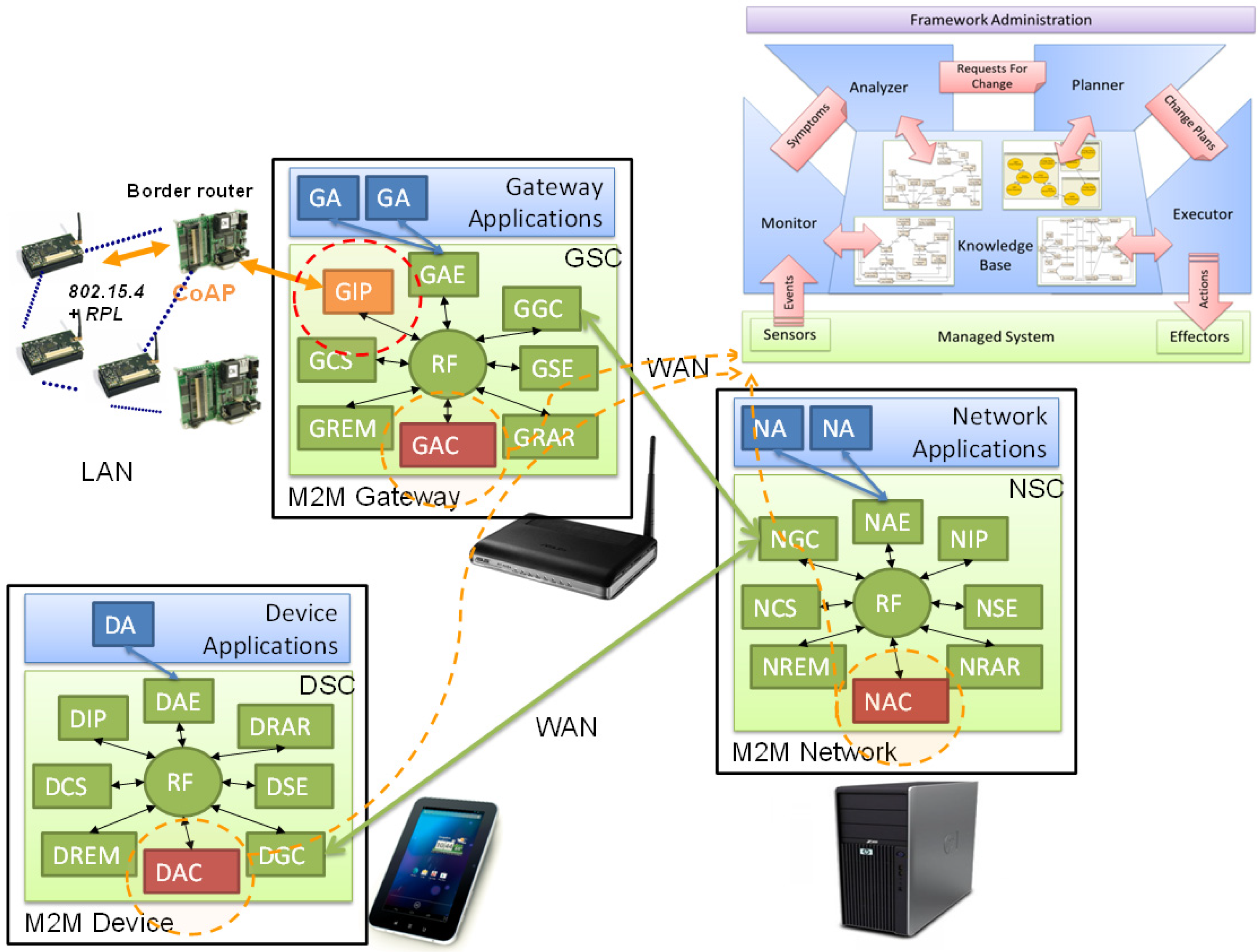
  • Another challenge regarding the place of semantic reasoning services in the Service Capability Layer. The Service Capability Layers were designed in a way so that they only act as serving hatch for information. Certain data may be sensitive and confidential, so they are often encrypted; only emitters and final receivers of this information have the necessary credentials to decrypt it. In this case, the semantic reasoner shall be placed somewhere in the data receiver application otherwise no reasoning can be done. From the implementation point of view, ETSI M2M SCL assumes that M2M applications know all the details of the device installation and data interpretation. This is challenging for M2M application developers, and therefore, autonomic service capabilities for Device Autonomic Capability (DAC), Gateway Autonomic capability (GAC), Network autonomic capability (NAC) are being created for SCL, to connect it smoothly with autonomic manager and information management, Figure 19. However, all the service capabilities are important to keep transparent for the information and let the autonomic M2M manager to enable control loop based on the M2M information;
  • The use of the different Service Capability Layers reduces the complexity of integrating new devices and reduces M2M applications development time. When a new device is deployed, it’s not necessary to readapt the existing systems (M2M Gateways, M2M Servers and backend applications). But the communication interfaces are quite complex to understand, an advanced knowledge of the ETSI M2M standard is necessary in order to develop applications and integrate new devices. Development APIs and frameworks shall be available for non ETSI developers;
  • The detailed evaluation results of the energy efficient caching system for Constrained Application Protocol (CoAP)-HTTP proxy have been presented in [72], and shortly summarized in the following. The simulation results show that the introduction of a caching architecture has energy saving impact in the system on the system performance, since it allows reducing the transmissions inside the WSN;
  • A multi-model, bi-layered framework is proposed in [73] to enhance the self-management of ETSI M2M systems. A graph-based representation built on top of the ETSI M2M standard constitutes respectively the formal and functional layers of the framework. In order to ensure inter-layers coherency, the model also comprises bi-directional communications between these two layers. The graph-based characterization allows the definition of consistency preserving reconfiguration mechanisms. On the other hand, it still possesses the functionalities granted by the standard, such as discovery protocols and machine interoperability;
  • The end-to-end security architecture model has been implemented in a prototype demonstrator using Arduino devices. The initial enrolment of the devices resulting in the definition of the long term credentials was performed using an out of band channel. The HTTP transport protocol was used both for communication with the authorization server and the M2M service platform. The evaluations show the provided architecture enable end to end data protection between devices and M2M/IoT applications and compatible with emerging interoperable M2M service platforms. Such architecture revolves around the use of an Oauth authorization server issuing digital access tokens serving both the purpose of protecting the data from one communication end to the other, and gaining access to the data distribution services offered by the M2M service platform. Apart from offering end to end data protection, this architecture makes possible to avoid data being available in clear at the level of the service platform therefore eliminating the possibility of data compromising at the platform level. In the next step, the prototype will be extended to include smaller devices too constrained to support http protocols. In this case, the CoAP will be used for communication between the device and the M2M service platform. The dialogue between the device and the authorization server take place via an intermediate CoAP/http proxy.

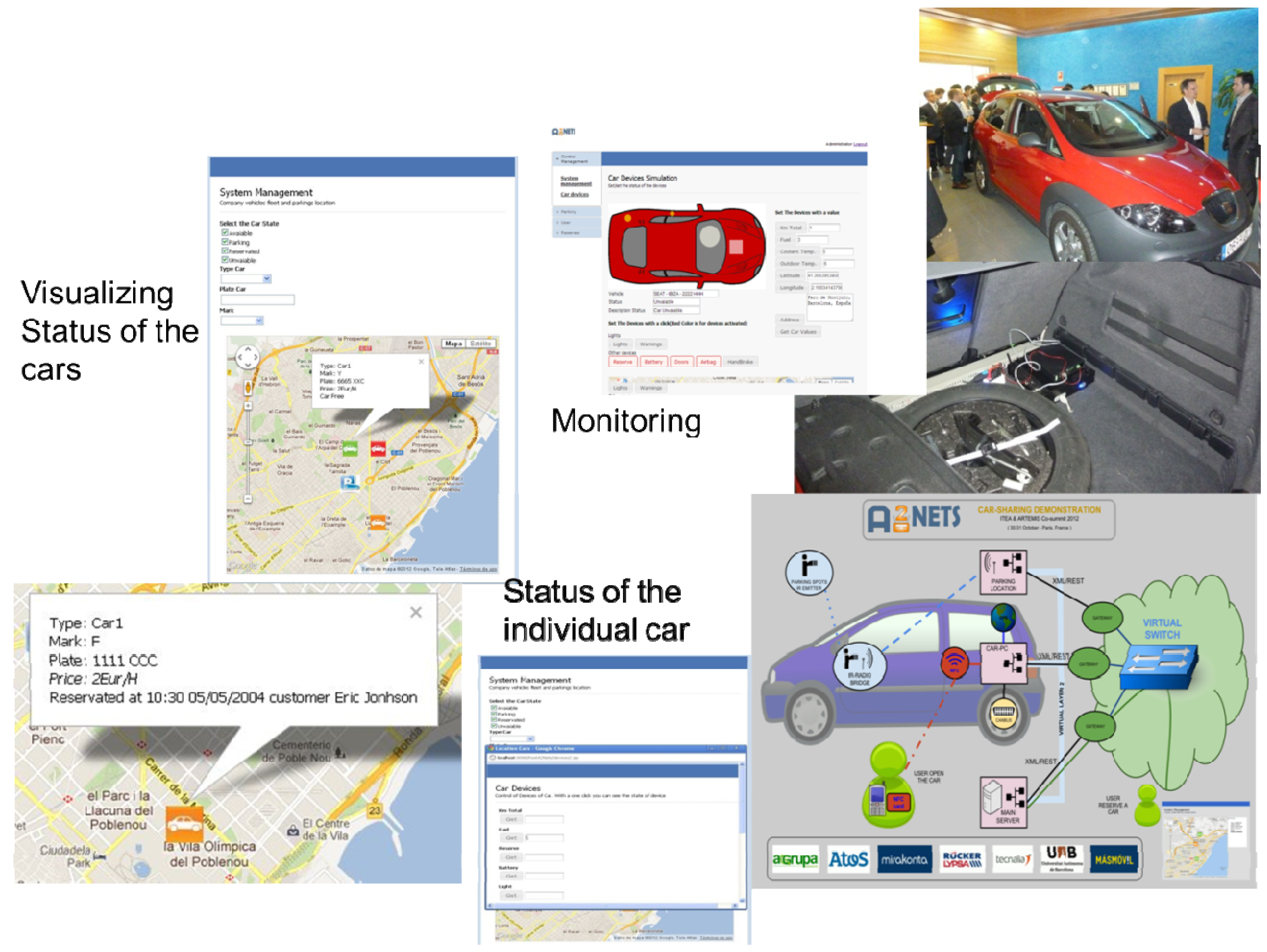
4.2. Car Sharing Experiment

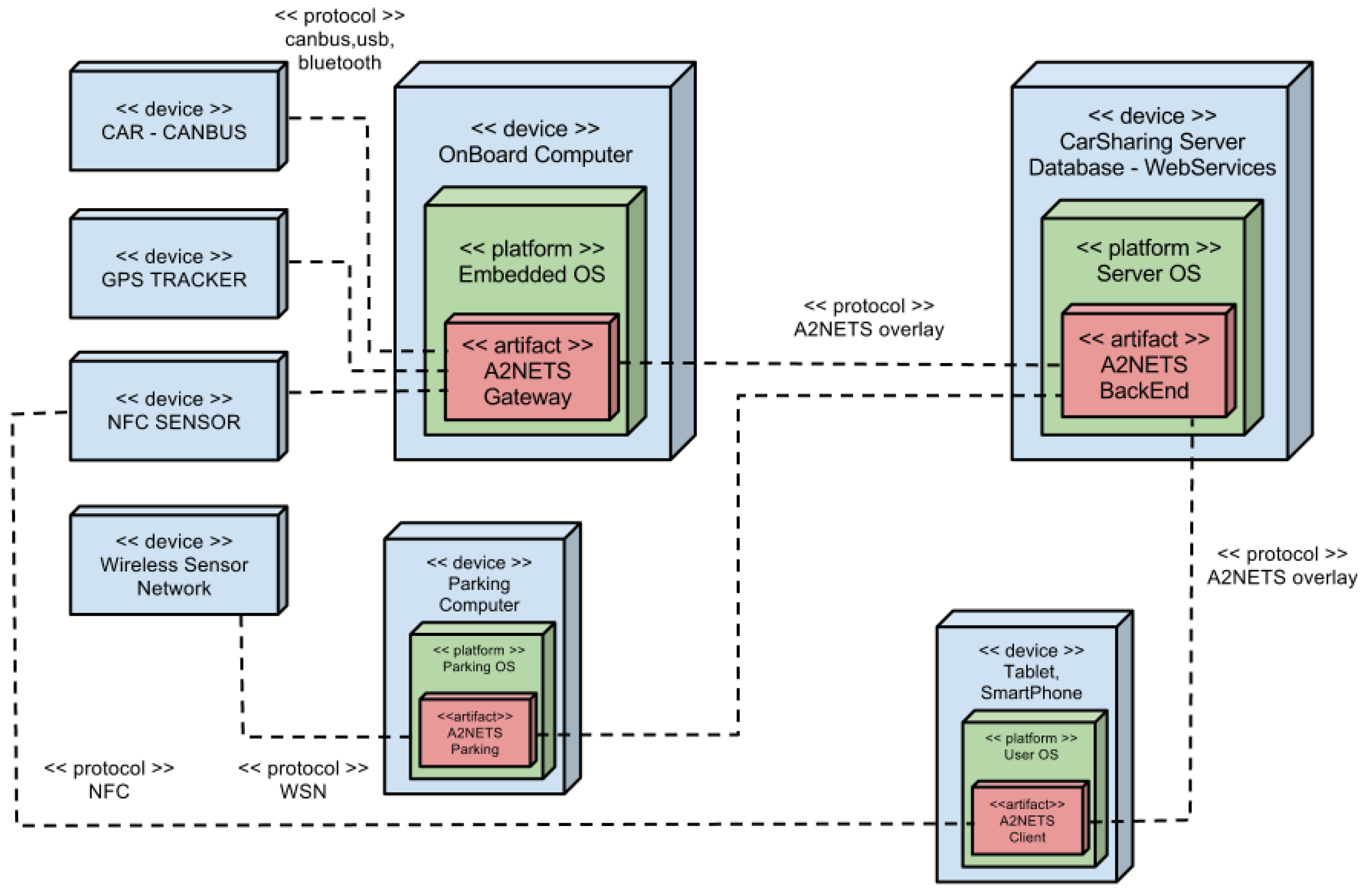
4.2.1. Car Sharing Case Description

The car sharing case has been visualized in Figure 20. The system has been built to provide real-time car sharing services such as e.g., monitoring the status and location of the cars etc. In the experimental system, a car is connected via 3G/GPRS to a Car-sharing web application that shows real time the relevant data that comes from the car. The data is collected by some sensors that can be placed in the car, in the parking spot, or in any other provider of the car sharing scenario. Also the data that manages the application can come from any other external provider of the car sharing business as the car maintenance provider, cleaning company etc.
For example, if the car sharing company wants to know the state of the doors, while the customer is using the car, we click on the button doors in the web application, this application sends (in a standard format) to the car the request of the state of the doors via the M2M gateway, and the car returns the data via standard XML-format. Or a Car-sharing customer wants to make a reservation, a code is sent to the customer for reserving a determinate car, after this the customer will be able to open the car with his mobile phone (NFC system). The idea is that the car is managed and monitored by the car sharing company, providing many services to the customer in order to rent the car whenever is necessary with the maximum flexibility.
Figure 20. Car sharing case.
Futureinternet 06 00261 g020
A key novel component of the system is the A2Nets Gateway functions executed within the on-board computer of the car. The gateway has three different connections to devices: CANBUS gets car values such as speed, fuel status, status of doors and windows, etc.; The GPS sensor provides the car localization; The NFC Sensor authenticates the user's from NFC tag or mobile device to allow open or close the door. In the car also there are wireless devices (IR and RADIO) that communicate with wireless sensors of the parking, so that they know the location of the vehicle inside the parking house. The A2Nets gateway connects the sensors into the back-office server.
The Server contains the general database system and a range of services to interact with other actors. From the car collects data in real time and historical of localization, speed, fuel, etc. From Parking gets the position of the place where is the vehicle to offer the customer who wants to rent it. Sends a customer keys to the car in order to client can open the door by NFC authentication. Also, allows client to make the reservation of a vehicle and know the basic statistics of client trip. When parking a wireless sensor detects the vehicle that is parked in a particular position. The Computer Parking automatically sends the data to the Car-Sharing company. Similarly, when the car leaves the parking, also sends information to the server. An UML deployment diagram for car sharing scenario is shown in Figure 21.
Figure 21. UMP deployment diagram of the car sharing scenario.
Futureinternet 06 00261 g021
The A2Nets gateway consist of components for both M2M service gateway and M2M overlay communication gateway as is shown in Figure 22. The M2M Service Gateway acts as an application level translator of messages between M2M capillary Networks to Overlay Communications protocol. For example, the messages from CANBUS and USB modules (NFC, GPS) needs to be translated to application level messages in formats applied by the back-office server. The M2M overlay communication gateway facilitates communication with all the devices of the system in a virtual network. For this purpose, the Communications Gateway establishes a Layer2 Tunnel to a Virtual switch through IP/SSL, similarly to OpenVPN Layer2 [74] and studies and definitions of L2VPN Working Group [75]. One of basics functions of the Communications Gateway is to establish the WAN connection (GPRS, 3G, xDSL, Satellite), maintain the connection, and change automatically the connection if the active is in failure or constrained. For example, in some cases, when 3G signal is low, the connection is less stable than in GPRS, and is better to change to 2G and communicate with a lower bandwidth but with more stability.
Figure 22. Car-sharing Communication gateway.
Futureinternet 06 00261 g022

4.2.2. Evaluation Results

The main evaluation results are shortly overviewed in the following:
  • Parking service system can be applied without making changes into the existing system as the result from applying A2Nets M2M gateway, which hides the complexity related to local network within a parking lot;
  • The complexity related to the on-board system within a car (CANBUS) and related car sensors applying GPS, NFC etc. is hidden by the A2Nets gateway. This is important because usually different types of cars apply different formats with the CANBUS and sensor devices within the car;
  • Application of XML based communication in the application level M2M information exchange between Web Server, M2M clients, Gateways and Car-PC Unit offer big advantages such as improvements in scalability, simplicity and interoperability because it is an open standard. In addition, thanks to XML, adding and modifying vehicle data has been easy for the car sharing company. An example of xml message between Car-PC Unit and car sharing Web Server is the following:
     <?xml version='1.0' encoding='UTF-8' ?>
        <car>
           <km>5000 </km>
           <fuel> 45 </fuel>
           <reserve> NO </reserve>
           <battery> 12 </battery>
           <lights> ON </lights>
           <doors> CLOSE </doors>
           <coolantTemp> 90 </coolantTemp>
           <outdoorTemp> 20 </outdoorTemp>
           <airbag> OFF </airbag>
           <handBreak> NO </handBreak>
           <lat> 41.355613</lat>
           <long> 2.070432 </long>
        </car>
  • The problems encountered when implementing the localization system, have been how to detect as in spaces so small and contiguous (2 meters width), the positioning of a vehicle, without installation of wiring components. If the location is within a closed parking, parking spaces are contiguous, and the receiver is installed in the windshield of the car, has had to adjust directionality IR emitter parking spots, installed on the roof of the plaza to not detect adjacent places. If the parking is open, it must be installed bars or brackets on each parking space to locate the vehicle, because there is no ceiling to install the IR emitter parking spots. The communication with the backend through the services offered by the Gateway has allowed the integration to proceed in a simple and efficient manner;
  • The A2Nets architectural approach proved to be very useful, because it allows development of service interaction and communication within the car and between different sites in smooth way even if each of them belongs to different domains and the needs arises from different requirements;
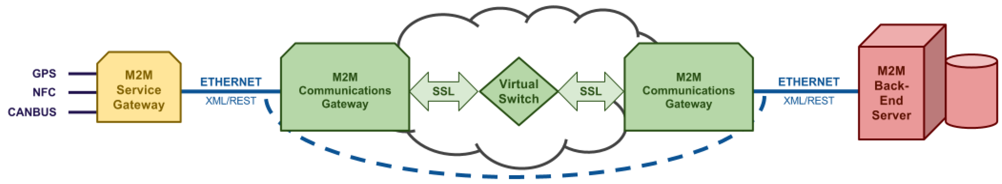
  • The application of virtualization techniques with Layer2 Tunneling has brought a management efficient of IP mobility, which does not affect the upper communication layers, avoiding problems of IP addressing like changes of IP addresses and routing (NAT) that can be found in communication technologies of the different operators;
  • The application of a virtual network with Layer2 Tunneling approach proved to be useful in maintaining WAN connection (GPRS, 3G, xDSL, Satellite), and switching it automatically in failure or constrained situation, without changes in upper communication layers. For example, in some cases, when 3G signal is low and connection is not stable, and is better to change to GPRS and communicate with a lower bandwidth but with more stability;
  • The system performance needs to depend on the coverage and capacity of telecom networks. Some areas may lack of 3G/GPRS coverage and there are also places where capacity is in full use. For example, it was required to change into the GPRS in the exhibition place in Paris (ITEA2 Co-summit event).

4.3. Electric Bike Experiment

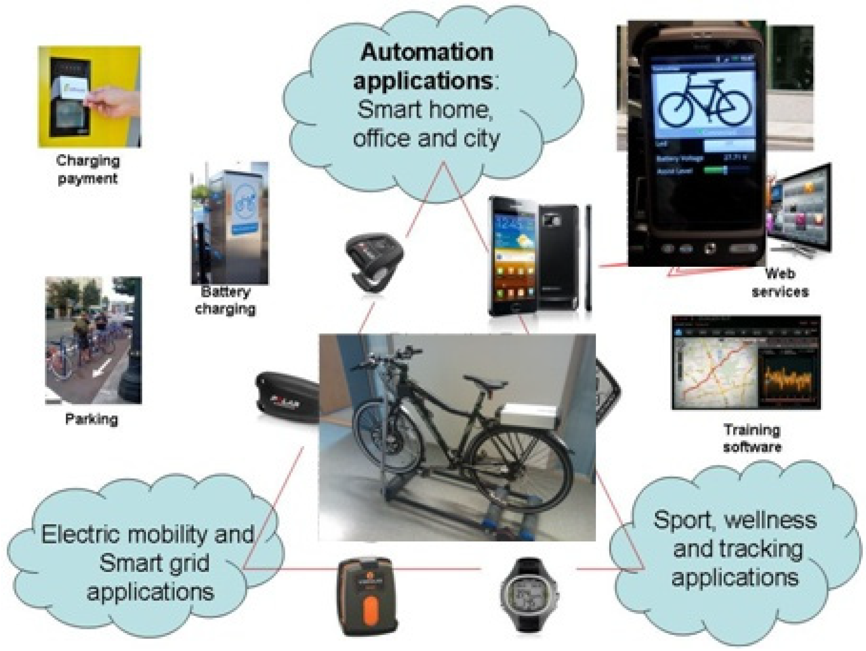
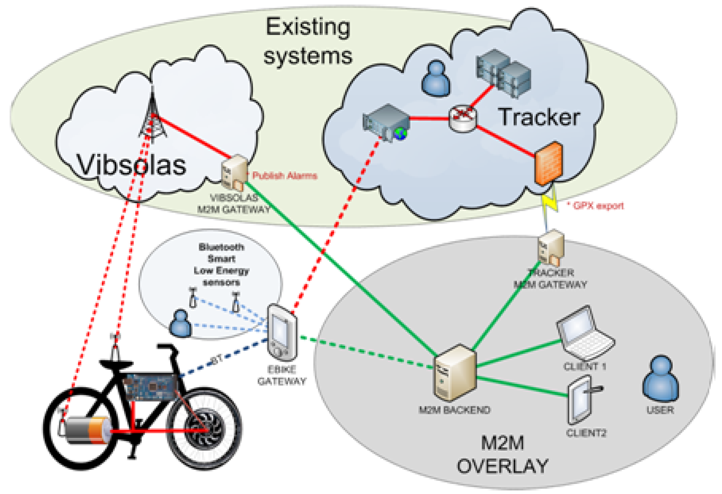
4.3.1. Electric Bike Case Description

A view to the electric bike ecosystem is visualized in Figure 23. The electric bike and its’ user establishes a mobile, dynamic embedded network consisting of sensors and actuators, which can be connected with smart homes/offices, sport and wellness applications and even with smart grids applications. The main components of the electric bike experimental system are shown in Figure 24. The novel prototyped components are service connection with Bluetooth low energy sensors, M2M gateway and its deployment (electric bike, Vibsolas sensor service system and Tracker tracking service system), and M2M communication overlay relying on XMPP.
The deployment diagram of the electric bike system is visualized in Figure 25. The system consists of the following communication links:
Communication links between M2M asset devices and M2M gateway. An example of this link is low power Bluetooth smart link between sensor and mobile phone acting as a M2M gateway.
  • Communication links between M2M gateways and M2M infrastructure. An example of this link is 3G Mobile Internet link between mobile phone (M2M gateway) and M2M back end service infrastructure;
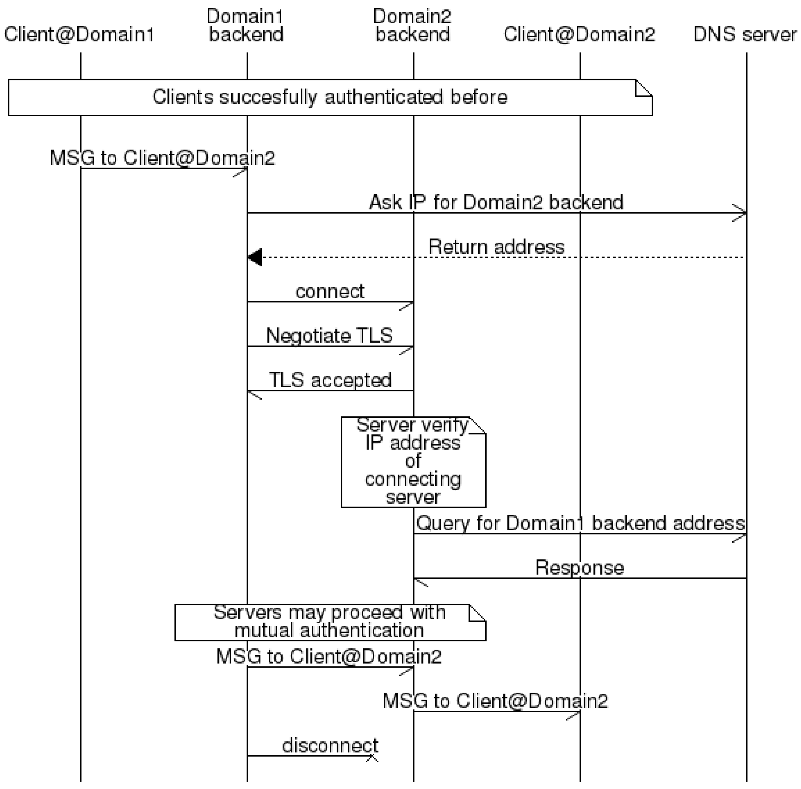
  • Communication links between M2M backend servers. An example of this link is Internet link between different vendors or domains;
  • Communication links between M2M backend servers and clients. An example of this link is link between sport, wellness and tracking application server and user clients.
Figure 23. Electric Bike Ecosystem.
Futureinternet 06 00261 g023
Figure 24. The main components of the electric bike experimental system.
Futureinternet 06 00261 g024
Figure 25. Deployment diagram of electric bike system.
Futureinternet 06 00261 g025
The links between M2M asset devices need to take in concern the limited capabilities of devices. In our experiment, we applied Bluetooth and Bluetooth Smart devices, and relied on standard Bluetooth profiles. The goal was to publish sensor data for multiple users and provide a way for controlling them. The challenge was that the devices didn’t understand any network protocol. Therefore, M2M Gateway is used for transforming sensor data to the format applicable for XMPP communication overlay, and delivering this data trough overlay network to the XMPP back-office server. The first steps of connecting and creating the device metadata are shown in Figure 26.
Mobile M2M client devices need at least one static server to connect to. Here we refer this static central point as XMPP back end server, which needs a static DNS-name or a static IP-address for clients to be able to utilize it. The back end server also provides most of the core communication services that are used by the client devices in order to communicate and interact with each other. The core communication services provided by the back end derive from the M2M communication overlay protocol that is XMPP [32,33]. Standard XMPP server has been applied here to allow faster development time and rich set of enhancement software packages.
An example of such multi-domain communication in the experimental system is deployment of M2M gateway with Tracker tracking service, Figure 24. The Tracker service system works independently using its own logics to collect and store data from the devices into the back-office server of Tracker. Tracker Live system has an application interface (API), which allows third party to request data in GPX format. In the solution, the Tracker M2M gateway acts as “Client of Domain2”, which acts as the third party, request data in GPX format and transform the data messages to be transferred via the XMPP based M2M communication overlay.
Figure 26. Connections of M2M Gateway.
Futureinternet 06 00261 g026

4.3.2. Evaluation Results

The main evaluation results are shortly overviewed in the following:
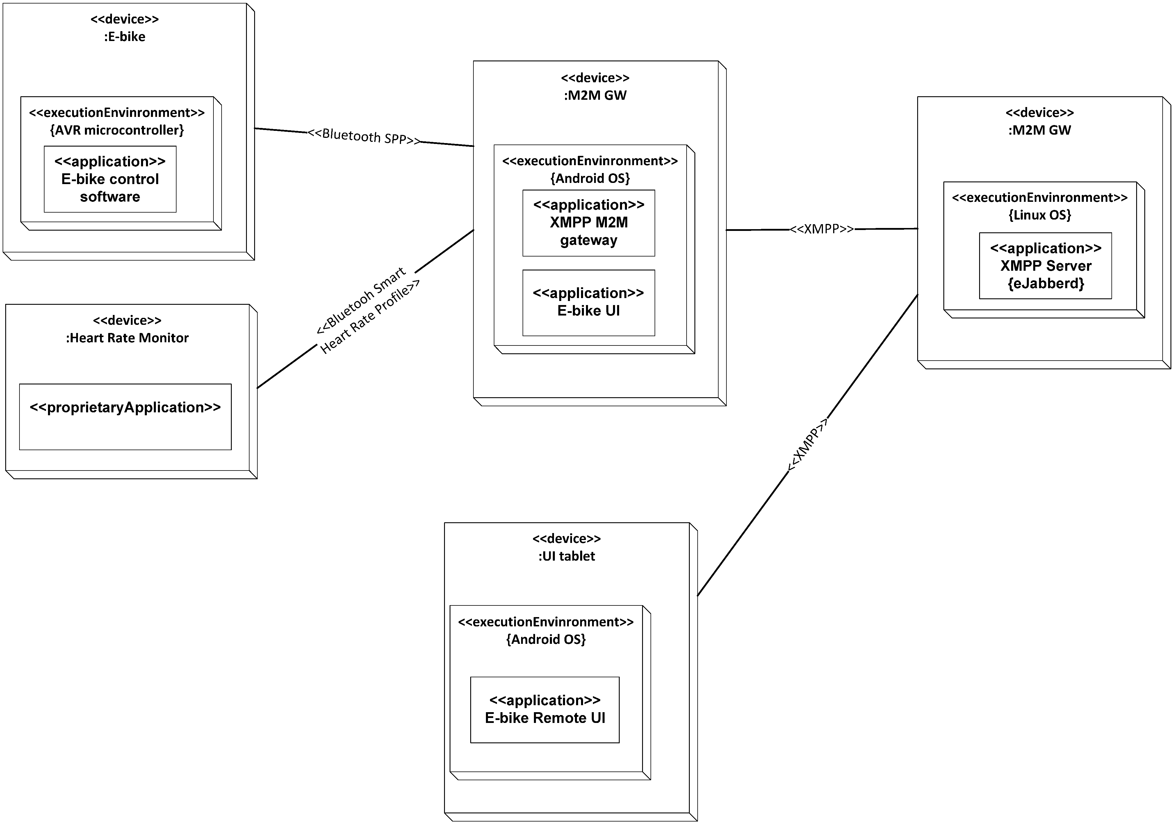
  • In the electric bike experiment, the selected approach relying on the XMPP based communication overlay proved to be good selection, because XMPP provided easily extendable XML based standard solution for e.g., addressing, messaging and publish subscribe methods;
  • XMPP uses distributed client to server architecture, in which the back-end server manages the user accounts. In this kind of a model, handling of user accounts is distributed between domains in such a way that each domain is able to handle it’s’ account policies according to their business model. For example, each machine has its’ own user-ids or that every machine uses its owners account;
  • XMPP provides quite solid background for enabling end-to-end security (“End-to-End Signing and Object Encryption” [76]), however, in this phase of the experiment they have not been evaluated and therefore more studies are needed.
  • In the electric bike experiments, Android mobile phone is applied as the M2M gateway. Realizing a working gateway operating with Bluetooth Smart devices was challenging because of limited support of the Android for Bluetooth Smart at the development time of the experiment;
  • The XMPP feature to support multi-domain communication proved to be very useful, because the service systems connected with electric bike system were mostly developed independently in vendor specific way;
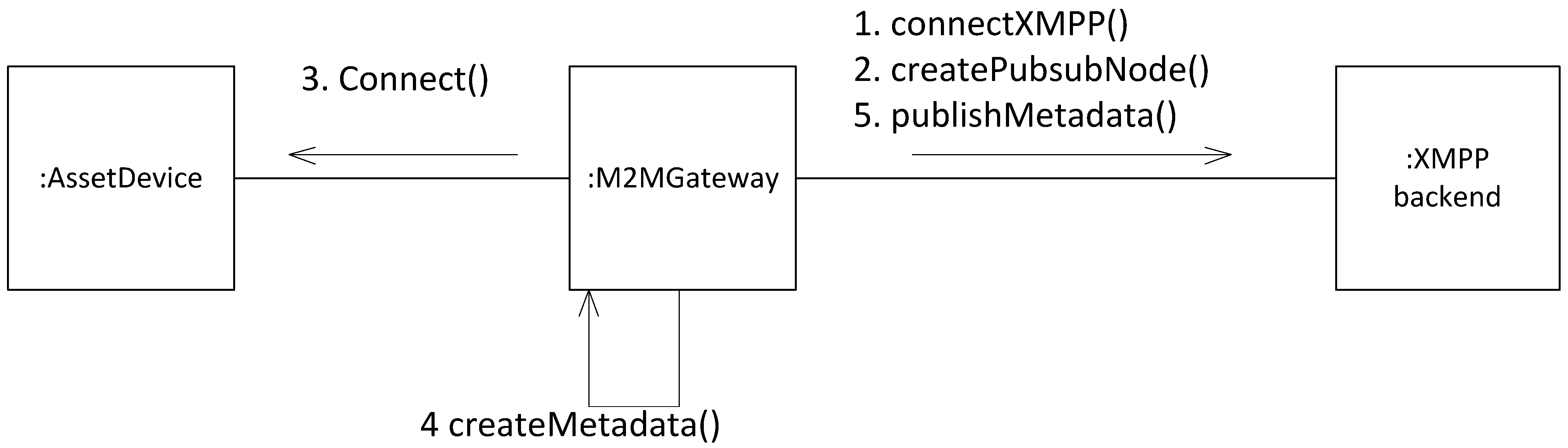
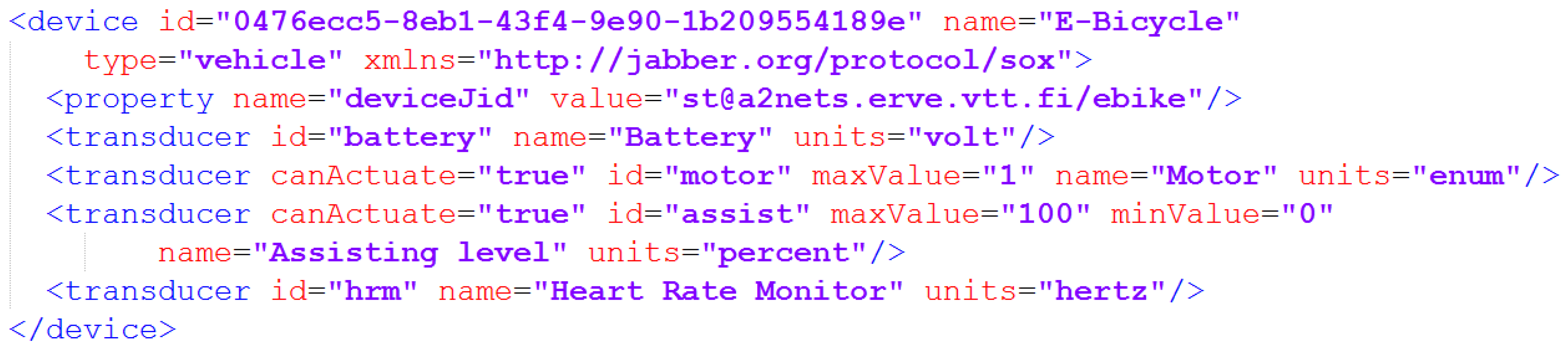
  • The Sensor-Over-XMPP extension was applied in the experiment to describe the metadata of devices in XML. It defines a “<device>” XML element, which may contain unlimited numbers of “<transducer>” elements, Figure 27. These two elements are used for describing properties of the devices, each of which can have multiple sensors and/or actuators. A device shall have a human friendly name, and unique identifier (according to RFC 4122). The Sensor-Over-XMPP proved to be simple way for delivering sensor data and controlling the devices in the experiment. However, interaction with service capabilities layer and autonomic M2M manager may require additional works and usage of other extensions too;
  • A prototype heart rate sensor has been developed with IPv6/COAP on top of a Bluetooth 4.0 stack. It seems that the first generation smart circuit was not an optimal choice, but rather what was available for prototyping. The SAR and FAR operations could not be properly implemented, but it is not affecting into the results significantly. The data was a one byte heart rate value. Particular care must be taken to minimize the data formats as it is easy to trigger FAR due to the small link layer packet size. The system exchanges more information at start but after a few seconds typically 4 packets are exchanged per second. The system could run roughly 90 hours on a CR-2025 coin cell. This can be compared to a standard GATT solution running for 200 hours on the same hardware. Future Bluetooth core optimizations in development are expected to improve the result significantly. However, the overall conclusion is that the architecture is very much feasible for future M2M systems.
Figure 27. Example of device metadata for electric bike.
Futureinternet 06 00261 g027

4.4. Discussion

There are/have been several other initiatives and projects working in the area for creation of a kind of Internet of things architecture such as e.g., Fi-Ware, Hydra, Runes, IoT-A, iCore and Sofia. Each of these projects has had different application cases into which they have focused, the resulting architectures have been interoperable only within the referred project and their approaches have varied from relying on open source solutions, some open API based implementations and own interpretation on applied standards. Here, one of the projects has been selected for comparison, and provided architectural principles are compared in the applicable level with main blocks of generic elements (GE) of FI-Ware architecture [51] in the Table 2. It is seen that the provided architectural principles are quite well in line with Fi-Ware architecture, however, an essential difference seems to be that we rely more on open standards and have an open multiple stakeholder system as the goal, and FI-Ware is more relying on open API based implementations of specific industrial companies. However, it is estimated that there are several lessons to be learned from Fi-Ware architecture and related evaluations, applicability of some parts and GEs related to M2M information management, M2M security and interaction with constrained embedded M2M devices are open areas for future research.
The evaluation of the architecture principles have been carried out in such a manner that main enablers have been developed and evaluated in different experimental systems in parallel as described earlier. This means that the key enablers have not yet been integrated and executed within a single end to end experimental scenario, which means that performance analysis of the complete system has not yet been feasible to be done. However, the aim in the next step is to create a combined experimental system, where the key enablers are executed in an integrated manner. It is planned and expected that in that phase also quantitative results related to performance can be evaluated.
Table 2. Comparison.
GEs of Fi-Ware architectureComparison with provided architectural principles
Cloud hostingIt is seen that the provided architectural principles are agnostic of the cloud hosting, in the sense that it is expected that resulting information and service layer could be executed as the platform within a cloud. However, this kind of hosting has not yet been evaluated.
Data/context managementIt is seen the autonomic M2M manager could apply GEs of data/context management as means for working with the information & knowledge bases. However, it is here estimated that this area is still open area for research, because of heterogeneous M2M application domains
Internet of Things (IoT) services enablementIt is seen that the ETSI M2M service capability layer is quite comparable solution with the generic enablers of Fi-ware related to services enablement. However, we rely in our work more on the open standards based solutions than open API based solutions provided by specific companies.
Application/services ecosystem and delivery frameworkIt is seen that the provided architectural principles are agnostic of the application/services ecosystem and delivery framework, in the sense that it is expected that developed service solutions could be delivered via any delivery framework. However, this kind of application delivery has not yet been evaluated.
SecurityOur contribution to security part is related to enabling end to end security and trust for the M2M system. This is quite limited compared with the Fi-Ware generic enablers for security, and it isn’t possible to compare properly the approaches for end to end security and creation of trust when writing this publication. It is here estimated that this area is still open for research, because of multiple views into the ownership of M2M devices and information, and the related business aspects.
Interface to Networks and DevicesOur contribution relies on the XMPP based M2M communication overlay, which hides the heterogeneity of networks to the services. The relationship of it with the Fi-Ware I2ND GEs is not clear, and a potential overlapping with ETSI M2M service capability layer has been detected. However, any proper evaluation with Fi-Ware I2ND GEs has not yet been done.

5. Conclusions

A set of architectural principles and key enablers for the horizontal architecture have been specified in this work in order to contribute towards solving the grand challenges related to complexity and “vertical silos” limiting the M2M market scale and interoperability. A selected set of key enablers called as autonomic M2M manager, M2M service capabilities, M2M messaging system, M2M gateways towards energy constrained M2M asset devices and creation of trust to enable end-to-end security for M2M applications have been developed. The developed key enablers have been evaluated separately in different scenarios dealing with smart metering, car sharing and electric bike experiments.
The evaluation results show that the provided architectural principles, and developed key enablers establish a solid ground for future research and seem to enable communication between objects and applications, which are not initially been designed to communicate together.. The aim as the next step in this research is to create a combined experimental system in order to evaluate the system interoperability and performance in a more detailed manner. In addition, it is seen that especially the areas related to M2M information management, M2M security and interaction with constrained embedded M2M devices are open areas for future research.

Acknowledgments

This review is related to deliverables of ITEA2 A2Nets project dealing with autonomic M2M service networks. The authors wish to thank all contributors of A2Nets project, and especially the ITEA2 officers, A2Nets reviewers and public research funding organizations in Spain, France, Turkey and Finland for making this work possible.

Conflicts of Interest

The authors declare no conflict of interest.

Author Contributions

Mahdi Ben Alaya has contributed especially into Section 3.1 and Section 4.1.2; Herve Ganem into Section 3.6 and Section 4.1.2.; Bashar Jubeh into Section 3.2 and Section 4.1; Antti Iivari into Section 2.2 and Section 4.3.1; Jeremie Leguay into Section 3.4 and Section 4.1.2; Jaume Martin Bosch into Section 4.2 and Niclas Granqvist into Section 3.5 and Section 4.3.2; Juhani Latvakoski has contributed into all sections.

References

  1. Miorandi, D.; Sicari, S.; de Pellegrini, F.; Chlamtac, I. Internet of things: Vision, applications and research challenges. Ad Hoc Netw. 2012, 10, 1497–1516. [Google Scholar] [CrossRef]
  2. Wu, G.; Talwar, S.; Johnsson, K.; Himayat, N.; Johnson, K. M2M: From mobile to embedded Internet. IEEE Commun. Mag. 2011, 49, 36–43. [Google Scholar]
  3. IPSO Alliance Enabling the Internet of Things. Available online: http://www.ipso-alliance.org/ (accessed on 17 April 2014).
  4. Internet Engineering Task Force (IETF). Available online: http://www.ietf.org/ (accessed on 17 April 2014).
  5. European Telecommunication Standards Institute (ETSI) M2M. Available online: http://www.etsi.org/m2m/ (accessed on 17 April 2014).
  6. Latvakoski, J.; Iivari, A.; Vitic, P.; Jubeh, B.; Alaya, M.B.; Monteil, T.; Lopez, J.; Talavera, G.; Gonzalez, J.; Granquist, N.; Kellil, M.; Ganem, H.; Väisänen, T. A survey on autonomic M2M service networks. Computers 2013. Submitted. [Google Scholar]
  7. Constrained RESTful Environments (CoRE) WG. Available online: http://tools.ietf.org/wg/core/ (accessed on 17 April 2014).
  8. Shelby, Z. Constrained RESTful Environments (CoRE) Link Format. IETF RFC 6690. August 2012. Available online: http://tools.ietf.org/html/rfc6690 (accessed on 20 February 2014).
  9. IETF Routing over Low Power and Lossy Networks (ROLL) WG. Available online: http://tools.ietf.org/wg/roll/ (accessed on 17 April 2014).
  10. Bluetooth SIG. The Bluetooth Core specification, v4.0; Bluetooth SIG: San Jose, CA, USA, 2010.
  11. Rescorla, E.; Modadugu, N. Datagram Transport Layer Security. IETF RFC 4347. April 2006. Available online: http://www.ietf.org/rfc/rfc2779.txt (accessed on 20 February 2014).
  12. Kent, S. IP Encapsulating Security Payload (ESP). IETF RFC 4303. December 2005. Available online: http://tools.ietf.org/rfc/rfc4303.txt (accessed on 20 February 2014).
  13. Yegin, A.; Shelby, Z. CoAP Security Options. IETF Internet-Draft. 14 October 2012. Expired 16 April. Available online: http://tools.ietf.org/html/draft-yegin-coap-security-options-00 (accessed on 20 February 2014).
  14. IETF IPv6 over Low Power WPAN (6LowPAN) WG. Available online: http://tools.ietf.org/wg/6lowpan (accessed on 17 April 2014).
  15. Hui, J. Compression Format for IPv6 Datagrams over IEEE 802.15.4-Based Networks. IETF RFC 6282. September 2011. Available online: http://tools.ietf.org/html/rfc6282 (accessed on 20 February 2014).
  16. Anonymous. Machine-to-Machine Communications (M2M) Functional Architecture. ETSI Technical Specification 102 690, V2.1.1. Available online: http://www.etsi.org/deliver/etsi_ts/102600_102699/102690/02.01.01_60/ts_102690v020101p.pdf (accessed on 20 February 2014).
  17. Anonymous. Machine-to-Machine Communications (M2M) mIa, DIa and mId Interfaces. ETSI TS 102 921, V2.1.1. December 2013. Available online: http://www.etsi.org/deliver/etsi_ts/102900_102999/102921/02.01.01_60/ts_102921v020101p.pdf (accessed on 20 February 2014).
  18. One M2M Forum. Available online: http://www.onem2m.org (accessed on 17 April 2014).
  19. OMA Device Management Tree and Description Serialization Specification. Version 1.2. Open Mobile Alliance Ltd.: San Diego, CA, USA, 2007.
  20. Device Data Model for TR-069; TR-181; Broadband Forum: Fremont, CA, USA, 2010.
  21. Jeronimo, M.; Weast, J. UPnP Design by Example: A Software Developer’s Guide to Universal Plug and Play; Intel Press: Santa Clara, CA, USA, 2003. [Google Scholar]
  22. Jammes, F.; Mensch, A.; Smit, H. Service-Oriented Device Communications Using the Devices Profile for Web Services. In Proceedings of the 3rd International Workshop on Middleware for Pervasive and Ad-Hoc Computing (MPAC ’05), New York, NY, USA, 11–15 July 2005; pp. 1–8.
  23. oBIX 1.0 Committee Specification 01; Organization for the Advancement of Structured Information Standards (OASIS): Burlington, MA, USA, 2006.
  24. Hannelius, T.; Salmenpera, M.; Kuikka, S. Roadmap to Adopting OPC UA. In Proceedings of the 6th IEEE International Conference on Industrial Informatics (INDIN 2008), Daejeon, Korea, 13–16 July 2008; pp. 756–761. [CrossRef]
  25. Martin, D.; Burstein, M.; Mcdermott, D.; Mcilraith, S.M; Paolucci, M.; Sycara, K.; Mcguinness, D.L.; Sirin, E.; Srinivasan, E. Bringing Semantics to Web Services with OWL-S. World Wide Web 2007, 10, 243–277. [Google Scholar] [CrossRef]
  26. Robin, A. OGC SWE Common Data Model Encoding Standard. Available online: http://www.opengis.net/doc/IS/SWE/2.0 (accessed on 20 February 2014).
  27. Cox, A. Observations and Measurements—XML Implementation. Version 2.0. 22 March 2011. Available online: http://www.opengis.net/doc/IS/OMXML/2.0 (accessed on 20 February 2014).
  28. Open Geospatial Consortium. Sensor Model Language (SensorML). OpenGIS Implementation Specification, Version 1.0.0. 2007. Available online: http://www.opengeospatial.org/ (accessed on 17 April 2014).
  29. Open Geospatial Consortium. OpenGIS SWE Service Model Implementation Standard. 2011. Available online: http://www.opengis.net/doc/IS/SWES/2.0 (accessed on 20 February 2014).
  30. Open Geospatial Consortium. Sensor Observation Service Implementation Standard, SOS. Version 1.0. 2007. Available online: http://www.opengeospatial.org/ (accessed on 17 April 2014).
  31. Open Geospatial Consortium. OGC Sensor Planning Service Implementation Standard SPS. 2011. Available online: http://www.opengis.net/doc/IS/SPS/2.0 (accessed on 20 February 2014).
  32. Saint-Andre, P.; Smith, K.; Tronçon, R. XMPP: The Definitive Guide; O’Reilly Media Inc: Sebastopol, CA, USA, 2009; pp. 1–306. [Google Scholar]
  33. Saint-Andre, P. Extensible Messaging and Presence Protocol (XMPP). IETF RFC 6120. March 2011. Available online: https://tools.ietf.org/html/rfc6120 (accessed on 20 February 2014).
  34. Day, M.; Aggarwal, S.; Mohr, G.; Vincent, J. Instant Messaging/Presence Protocol Requirements. IETF RFC 2779. February 2000. Available online: http://www.ietf.org/rfc/rfc2779.txt (accessed on 20 February 2014).
  35. Inhyok, C.; Shah, Y.; Schmidt, A.U.; Leicher, A.; Mayerstein, M.V. Trust in M2M Communications. IEEE Veh. Technol. Mag. 2009, 4, 69–75. [Google Scholar] [CrossRef]
  36. Raza, S.; Chung, T.; Duquennoy, S.; Yazar, D.; Voigt, T.; Roedig, U. Securing Internet of Things with Lightweigth IPsec; SICS Technical Report T2010:08; Lancaster University: Lancaster, UK, 2011. [Google Scholar]
  37. Judge, P.; Ammar, M. Security issues and solutions in multicast content distribution: A survey. IEEE Netw. 2003, 17, 30–36. [Google Scholar] [CrossRef]
  38. Kephart, J.O.; Chess, D.M. The vision of autonomic computing. IEEE Computer Soc. 2003, 36, 41–50. [Google Scholar] [CrossRef]
  39. Garlan, D.; Cheng, S.-W.; Huang, A.-C.; Schmerl, B.; Steenkiste, P. Rainbow: Architecture-based self-adaptation with reusable infrastructure. Computer 2004, 37, 46–54. [Google Scholar] [CrossRef]
  40. Nami, M.R.; Bertels, K. A Survey of Autonomic Computing Systems. In Proceedings of the 3rd International Conference on Autonomic and Autonomous Systems (ICAS’07), Athens, Greece, 19–25 June 2007; IEEE Computer Society: Washington, DC, USA, 2007. [Google Scholar]
  41. Want, R.; Pering, T.; Tennenhouse, D. Comparing autonomic and proactive computing. IBM Syst. J. 2003, 42, 129. [Google Scholar] [CrossRef]
  42. Rhea, S.; Wells, C.; Eaton, P.; Geels, D.; Zhao, B.; Weatherspoon, H.; Kubiatowicz, J. Maintenance-free global data storage. IEEE Internet Comput. 2001, 5, 40–49. [Google Scholar]
  43. Gurguis, S.A.; Zeid, A. Towards autonomic web services: Achieving self-healing using web services. SIGSOFT Softw. Eng. Notes 2005, 30, 1–5. [Google Scholar] [CrossRef]
  44. Appavoo, J.; Hui, K.; Soules, C.; Wisniewski, R.; Silva, D.; Krieger, O.; Marc, D.; Auslander, A.; Gamsa, B.; Ganger, G.; et al. Enabling autonomic behavior in systems software with hot-swapping. IBM Syst. J. 2003, 14, 60–76. [Google Scholar]
  45. Mills, K.; Rose, S.; Quirolgico, S.; Britton, M.; Tan, C. An autonomic failure-detection algorithm. ACM SIGSOFT Softw. Eng. Notes 2004, 29, 79–83. [Google Scholar] [CrossRef]
  46. Qin, F.; Tucek, J.; Sundaresan, J.; Zhou, Y. Rx: Treating bugs as allergies—A safe method to survive software failures. ACM SIGOPS Oper. Syst. Rev. 2005, 39, 1–14. [Google Scholar] [CrossRef]
  47. Kaiser, G.; Parekh, J.; Gross, P.; Valetto, G. Retrofitting Autonomic Capabilities onto Legacy Systems. J. Clust. Comput. 2005, 9, 141–159. [Google Scholar]
  48. Liu, H.; Parashar, M. Accord: A programming framework for autonomic applications. IEEE Trans. Syst. Man. Cybern. 2006, 36, 341–352. [Google Scholar] [CrossRef]
  49. Rossi, M. Initial IoT Protocol Suite Definition. IOT-A_WP3_D3.3. 12 April 2012. Available online: http://www.iot-a.eu/public/public-documents/documents-1/1/1/d3.3/at_download/file (accessed on 20 February 2014).
  50. The Anthill Project. Available online: http://www.cs.unibo.it/projects/anthill (accessed on 17 April 2014).
  51. Fi-Ware Project Architecture. Available online: http://forge.fi-ware.eu/plugins/mediawiki/wiki/fiware/index.php/FI-WARE_Architecture (accessed on 17 April 2014).
  52. Hydra Project. Available online: http://www.hydramiddleware.eu (accessed on 17 April 2014).
  53. Runes Project. Available online: http://www.ist-runes.org (accessed on 17 April 2014).
  54. IoT-A Project. Available online: http://www.iot-a.eu (accessed on 17 April 2014).
  55. ICore Project. Available online: http://www.iot-icore.eu (accessed on 17 April 2014).
  56. Sofia Project. Available online: http://www.artemis-ia.eu/project/index/view?project=4 (accessed on 17 April 2014).
  57. ETSI. Machine to Machine Communications. Available online: http://www.etsi.org/website/technologies/m2m.aspx (accessed on 17 April 2014).
  58. Cisco. Available online: http://www.fiercebroadbandwireless.com/story/cisco-introduces-small-m2m-gateway-businesses/2011-08-25 (accessed on 17 April 2014).
  59. AnyBridge. Available online: http://www.anybridge-m2m.nl/home (accessed on 17 April 2014).
  60. Systech. Available online: http://www.systech.com/ (accessed on 17 April 2014).
  61. Alcatel-Lucent. Available online: http://www2.alcatel-lucent.com/blogs/techzine/2011/getting-ready-for-m2m-traffic-growth/ (accessed on 17 April 2014).
  62. Androutsellis-Theotokis, S.; Spinellis, D. A survey of peer-to-peer content distribution technologies. ACM Comput. Surv. 2004, 36, 335–371. [Google Scholar] [CrossRef]
  63. Zheng, H.; Yan, M. Research and Analysis of the Optimization of the Unstructured P2P Overlay Networks. In Proceedings of the 5th International Conference on Wireless Communications, Networking and Mobile Computing (WiCOM’09), Beijing, China, 24–26 September 2009; IEEE Press: Piscataway, NJ, USA, 2009; pp. 4376–4379. [Google Scholar]
  64. Lua, E.K.; Crowcroft, J.; Pias, M.; Sharma, R.; Lim, S. A survey and comparison of peer-to-peer overlay network schemes. IEEE Commun. Surv. Tutor. 2005, 7, 72–93. [Google Scholar] [CrossRef]
  65. Alaya, M.B.; Monteil, T. Frameself: An ontology-based framework for the self-management of M2M systems. Concurr. Comput. Pract. Exp. 2006, 18. [Google Scholar] [CrossRef]
  66. Manish, P.; Hariri, S. Autonomic Computing: Concepts, Infrastructure, and Applications; CRC/Taylor and Francis Print: Boca Raton, FL, USA, 2007. [Google Scholar]
  67. Compton, M.; Barnaghi, P.; Bermudez, L.; García-Castro, R.; Corcho, O.; Cox, S.; Graybeal, J.; Hauswirth, M.; Henson, C.; Herzog, A.; et al. The SSN ontology of the W3C semantic sensor network incubator group. Web Semant. Sci. Serv. Agents World Wide Web 2012, 17, 25–32. [Google Scholar] [CrossRef] [Green Version]
  68. Fielding, R.T. Architectural Styles and the Design of Network-Based Software Architectures. Ph.D. Dissertation, University of California, Irvine, CA, USA, 2000. [Google Scholar]
  69. Bhatia, G.; Rowe, A.; Berges, M.; Spirakis, C. Sensor-over-XMPP. Prototype XEP, Version 0.0.18; 8 April 2011. Available online: http://xmpp.org/extensions/inbox/sensors.html (accessed on 20 February 2014).
  70. Kovatsch, M.; Duquennoy, S.; Dunkels, A. A Low-Power CoAP for Contiki. In Proceedings of the 2011 IEEE Workshop on Internet of Things Technology and Architectures (IoTech 2011), Valencia, Spain, 17 October 2011.
  71. Bluetooth SIG. Core Specification Addendum 3; Bluetooth SIG: San Jose, CA, USA, 2012. [Google Scholar]
  72. Leone, R.; Medagliani, P.; Leguay, J. Optimizing QoS in Wireless Sensor Networks using a Caching Platform. In Proceedings of the 2nd International Conference on Sensor Networks (Sensornets 2013), Barcelona, Spain, 19–21 February 2013.
  73. Eichler, C.; Gharbi, G.; Guermouche, N.; Monteil, T.; Stolf, P. Graph-Based Formalism for Machine-to-Machine Self-Managed Communications. In Proceedings of the IEEE 22nd International Workshop on Enabling Technologies: Infrastructure for Collaborative Enterprises (WETICE 2013), Hammamet, Tunisia, 17–20 June 2013; pp. 74–79.
  74. Site-to-Site Layer 2 Bridging Using OpenVPN. Available online: http://docs.openvpn.net/how-to-tutorialsguides/virtual-platforms/site-to-site-layer-2-bridging-using-openvpn-access-server/ (accessed on 20 February 2014).
  75. IETF. Layer 2 Virtual Private Networks (l2vpn) Working Group. Available online: http://datatracker.ietf.org/wg/l2vpn/charter/ (accessed on 20 February 2014).
  76. Saint-Andre, P. End-to-End Signing and Object Encryption. IETF RFC3923. October 2004. Available online: http://www.ietf.org/rfc/rfc3923.txt (accessed on 20 February 2014).

