1. Introduction
Cloud computing has drastically changed the way in which we consume IT resources. Unlike traditional data centers, clouds offer elasticity—the ability to reserve and free resources flexibly (often within minutes); pay-as-you-go—users only pay for the resources they actually consume; and standardization—through the use of virtualization and the offering of runtime platforms by providers, application middleware and hardware stacks are commoditized. Because of these new environmental properties, the architecture and management of applications have to be adjusted as well. However, the fast and mostly industry-driven evolution of cloud offerings often obfuscates the common concepts of offered solutions. Due to different requirements of applications and the components they consist of, offerings of different cloud providers have to be integrated in many cases. Using only one cloud provider for the complete application landscape of a company is, therefore, often impossible.
We consider cloud applications to be divided into loosely coupled application components so that individual application components can use different cloud offerings which best fit their requirements. Applications components are developed specifically for one cloud offering and requirements are often not explicitly specified. Exchanging cloud offerings after the initial development of the application, therefore, remains a challenge. To describe requirements of application components in a more generic form, we have abstracted the development guidelines for specific cloud providers. The obtained common architectural principles were compiled into a uniform
pattern format in [
1] and are available online (
http://cloudcomputingpatterns.org). These patterns describe good solutions to common problems in the area of cloud computing as well as clouds and their offerings. Especially, they allow the classification of cloud providers regarding the patterns they support and, thus, ease application development and requirements management.
Building on these patterns, describing architectural concepts of cloud application development, we now focus on the runtime management of cloud applications. The runtime management of applications is often comprised of manual tasks that are performed according to implicit knowledge of application managers. Such tasks are, for example, adequate resource adjustments to changing workloads or reactions to failing system resources. Cloud computing has introduced additional challenges to the runtime management of such applications: (i) its use is often most beneficial, if application management is automated, for example, to exploit pay-as-you-go pricing models more efficiently; (ii) to address the often low availability of individual cloud resources, an automation of resiliency management is required to address resource failure [
2]; and (iii) vendor lock-ins can be avoided if application components can be moved automatically between different environments.
The remainder of this article is structured as follows. In
Section 2, we align the new management challenges of cloud applications with existing IT management approaches and give examples of how today’s cloud providers address and automate them. Existing work on the offering process of cloud application is also covered in this section. We extend this process to incorporate the definition of automated management flows as an integral part of application development. In
Section 3, we then give an overview of existing patterns that we organized in a catalog.
Section 4 introduces a new pattern class for cloud application management patterns to be included in this catalog. Just as architectural patterns are used to guide the implementation of applications, management patterns will guide the creation of automated management processes.
Section 5 covers annotations of implementation artifacts to patterns to guide application developers and application managers. For example, we propose to annotate information about management interfaces to be used during the creation of automated management flows. We argue that this respects the flexibility and speed that cloud computing has introduced to systems management tasks, such as provisioning, deprovisioning, and scaling of resources. Further, it enables application managers to address future challenges, for example, to automate the replacement of a cloud provider with a different one or with an in-house data center during the design time. Such annotations can also help to standardize pattern implementation which enables companies to control the allowed runtime environments. The otherwise deployment of applications on arbitrary hard- and middleware increases the management complexity drastically [
3]. In
Section 6, we employ the proposed approach in an end-to-end example describing the pattern-based development of a web shop application. Especially, we show how patterns can be used to express requirements of application components as part of an architecture diagram. We cover how management flows can be created in a standardized fashion by refining abstract management flows to executable ones. Finally,
Section 7 covers limitations of the approach and gives an outlook on the future research that will address them.
4. Cloud Application Management Patterns
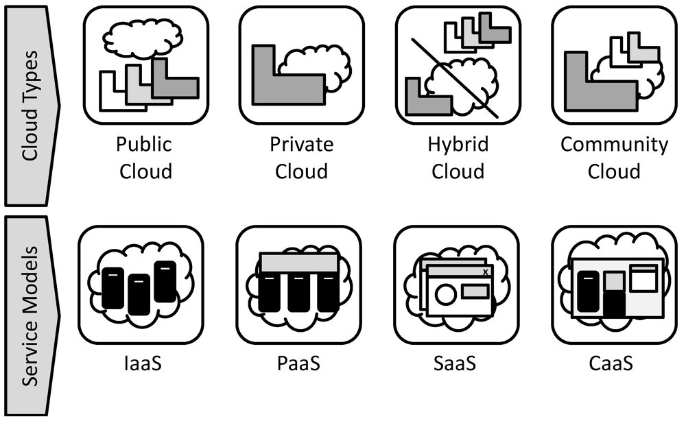
Previously discovered patterns for cloud architectures, cloud offerings, cloud types, and cloud service models have been described in
Section 3. In this section, we introduce a new pattern class,
cloud application management patterns. While cloud architecture patterns mentioned in
Section 3.5 describe how application components shall be designed and interconnected, patterns of this class describe how application components should be managed. Therefore, the patterns of this class describe cross-cutting concerns how to manage cloud applications.
The management patterns follow the same pattern format described in
Section 3.2 to seamlessly integrate into the catalog. The only difference is that the sketch does not depict an abstract architectural diagram but an
abstract management flow using Business Process Model and Notation (BPMN) [
33]. This is due to the fact that management patterns are not implemented as application components but in the form of automated management flows.
In some cases, a specific system architecture is required for a management pattern to be applicable. For example, the following
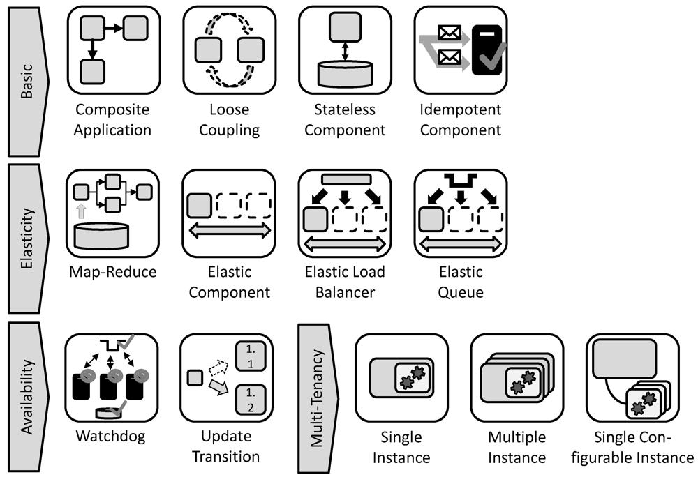
elasticity management pattern is likely to be combined with the application architecture patterns
elastic component,
elastic load balancer, or
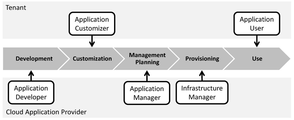
elastic queue. This is expressed through interrelations between the patterns rather than including duplicate descriptions of management flows in every architectural pattern. Another advantage of this separation is that the creation of application components and management processes performed by different roles of the cloud application offering process described in
Section 2.3. In the following, we present management patterns we discovered to handle the cloud-specific management challenges mentioned in
Section 2.2.
4.1. Elasticity Management Pattern
Icon: the icon of the
elasticity management pattern is depicted in
Figure 7.
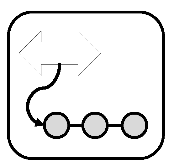
Figure 7.
Icon of the Elasticity Management Pattern.
Figure 7.
Icon of the Elasticity Management Pattern.
Driving Question:How can the number of resources to which application components are scaled-out be adjusted efficiently to the currently experienced workload?
Context: a componentized application is hosted on an elastic infrastructure and comprised of elastic components, elastic queues, or elastic load balancers.
Challenges: the dynamicity of clouds demands automatic scaling of cloud resources. To perform this task, the current resource demand has to be determined and has to be reflected in provisioning and deprovisioning of system resources.
Solution: analyze the current utilization of system resources after certain time intervals, when a user requests it, or based on monitored system events to determine the current workload and adjust resource numbers accordingly.
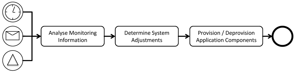
Result: the elasticity management flow can be triggered periodically (every day, month
etc.) depicted by the timer event in
Figure 8. Alternatively, a user of the application can trigger it, for example, because he knows that a number of new employees will start using the application at a certain date. This case is reflected by a message event passed to the management flow. As a third option, the flow can be triggered by signals originating from monitoring. For example, the size of a queue may exceed a certain threshold if this management pattern is combined with the
elastic queue pattern.
Figure 8.
Abstract Management Flow of the Elasticity Management Pattern.
Figure 8.
Abstract Management Flow of the Elasticity Management Pattern.
When the elasticity management flow is triggered, resource utilization is optimized and resource numbers are adjusted to correctly reflect the workload. Critical design decisions in this scope are:
Time interval at which system utilization is evaluated (in case of time-based triggers): if this interval is too large, the system may be underutilized or overloaded without notice.
Reactions to workload analysis: the reaction must be appropriate, for example, if too few resources are added to the system, it takes too long until an increased workload can be handled by the application.
Both design decisions mainly depend on heuristics and prior experiences. When determining the time interval at which utilization is measured, it has to be considered how quickly utilization has changed in the past. Also, the time it takes to provision new resources has to be considered here. This is also an important factor when determining how a change in the utilization should be addressed. Historic information, such as user behavior during holidays may be used to adjust these variables [
34].
Relations to other patterns: the elasticity management pattern can be combined with elastic components, elastic queues, or elastic load balancers. These patterns form the architectural basis for the elasticity management flow by providing the required monitoring information that has to be extracted from the managed application components and their runtime environment.
Variations: manual triggering of the introduced management flow may not only originate from application users. Who is responsible for this task mainly depends on the employed cloud service model. In case of IaaS, the user of the cloud likely performs this task. However, in case of PaaS and SaaS, the configuration of elasticity management may be hidden from the user. In this case, the task instead may be performed by the cloud provider.
Known Uses: [
2] describes how to scale Amazon AWS Resources. Especially, it covers different events and conditions when the elasticity management should be executed. [
35] evaluates the scaling capabilities of Windows Azure, for which [
36] offers a scaling software as a service. The concept to scale-out applications automatically is, however, not only seen in cloud computing and has been used by the industry for quite some time [
31].
Self-adaptive autonomous systems perform a similar management task to adjust their size, structure, communication channels,
etc. regarding environmental conditions. They undergo a so-called monitor-analyze-plan-execute (MAPE) loop [
37] comprised of similar steps as the elasticity management flow.
4.2. Resiliency Management Pattern
Icon: the icon of the
resiliency management pattern is depicted in
Figure 9.
Figure 9.
Icon of the Resiliency Management Pattern.
Figure 9.
Icon of the Resiliency Management Pattern.
Driving Question: How can the availability of a composite application be ensured even if individual components fail?
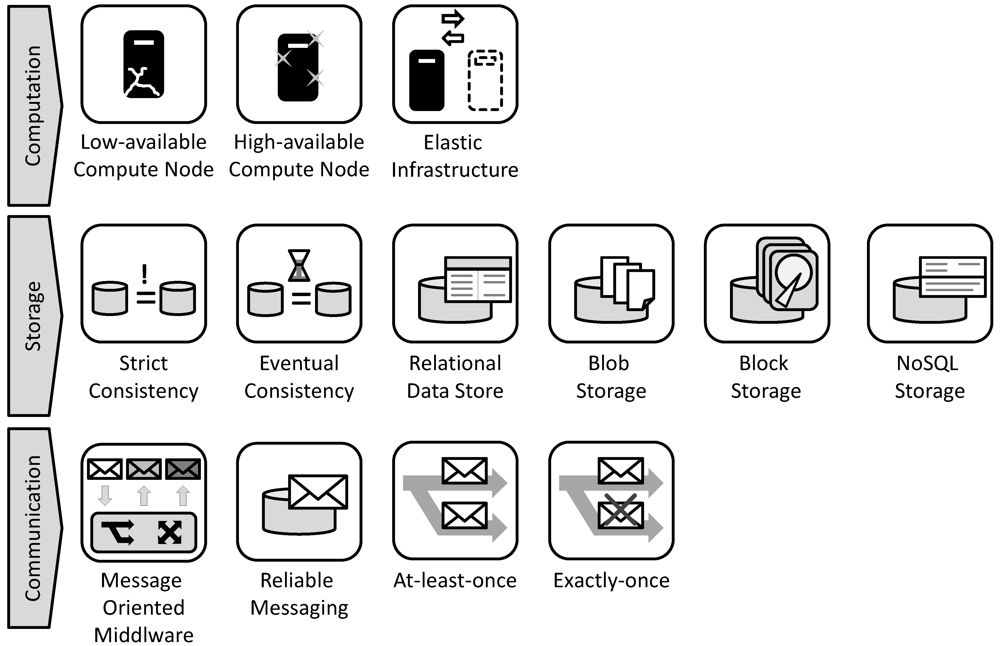
Context: a composite application that distributes application components among different low-availability compute nodes offered by an elastic infrastructure.
Challenges: if an application depends on the availability of many individual resources, the overall availability of the application is may be reduced drastically. This is due to the fact that the chance that at least one of the resources fails is higher, the more resources are used. Therefore, it has to be ensured that individual resources may fail without affecting the availability of the overall application.
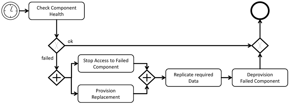
Solution: scale-out application components among multiple resources. Ensure that a sufficient threshold of component instances is provisioned exceeding what the currently experienced workload requires, monitor and react to component instance failures according to the abstract management flow depicted in
Figure 10.
Figure 10.
Abstract Management Flow of the Resiliency Management Pattern.
Figure 10.
Abstract Management Flow of the Resiliency Management Pattern.
Results: the failure of component instances can be detected and automatic reaction is enabled. Critical design decisions in this scope are:
The time intervals mainly depend on the required recovery time and, therefore, have to respect provisioning time of resources. Often, cloud providers do not make assurances for these times and heuristics have to be employed to predict them. To detect a component failure, providers may offer monitoring of network availability, CPU or memory utilization, for example [
11]. The application manager, however, is obligated to interpret these values and deduct information about application component availability from them. Further, none of this information can assure that the component functions correctly on the application level. Such tests have to be implemented manually by the application developer.
Variations: sometimes, failures are hard to detect on the application level. Especially, testing how application components behave after a very long runtime can be challenging. To address these challenges, application components can be randomly treated as failed after certain time intervals and are then replaced by newly provisioned instances.
Relations to other patterns: the components themselves should be implemented as stateless components to simplify their management within the scope of this pattern. The resiliency management pattern may be combined with the elasticity management pattern if elasticity is also an issue.
Known uses: The concept has been used to enable high availability of processes running on a single machine. In this scope, the system component handling the above described management flow is called a watchdog to which system components notify their availability [
38]. Amazon suggests a similar approach to assure fault tolerance in applications using their Elastic Beanstalk service [
39].
4.3. Move/Update Management with Downtime Pattern
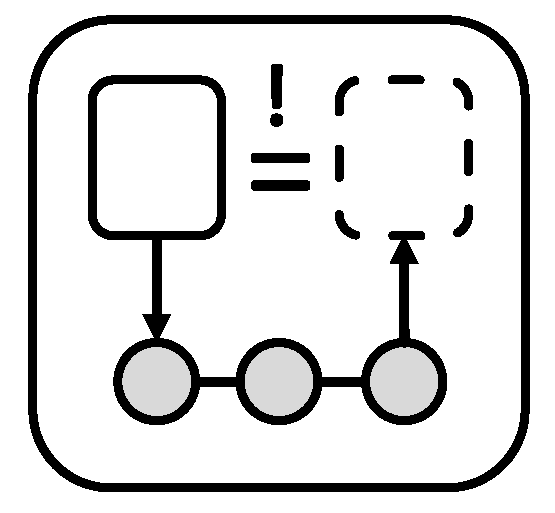
Icon: the icon of the
move/update management with downtime pattern is depicted in
Figure 11.
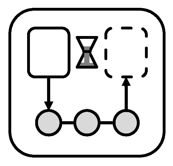
Figure 11.
Icon of the Move/Update Management with Downtime Pattern.
Figure 11.
Icon of the Move/Update Management with Downtime Pattern.
Driving Question:How can an application component be moved to a different environment or updated to a new software, middleware, or hardware version, if downtime is acceptable?
Context: a stateless application component, which has no internal state but, relies on external data and is part of a composite application. This component may be unavailable for the timeframe in which it is updated/moved.
Challenges: during the transition it has to be ensured that application components are idle prior to their deprovisioning. Further, accesses either have to be stopped on the application level or have to be queued during the downtime.
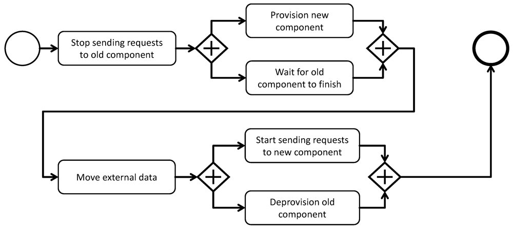
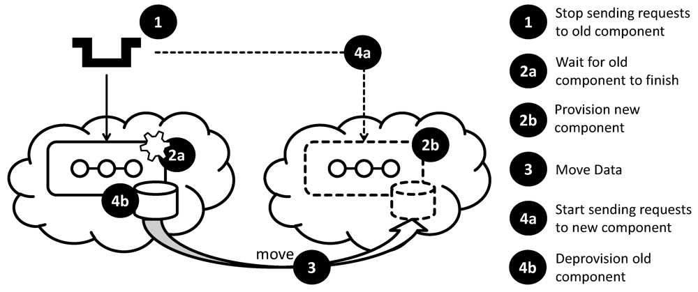
Solution: as depicted in
Figure 12, ensure that no new requests are sent to the component to be moved or updated. Then, provision a new component instance with the new version (update) or in the new runtime environment (move). Send requests to the new component when it becomes available and deprovision the old one once it has finished processing requests.
Figure 12.
Abstract Management Flow of the Move/Update Management with Downtime Pattern.
Figure 12.
Abstract Management Flow of the Move/Update Management with Downtime Pattern.
Result: the provisioning of the new component and the deprovisioning of the old component can partly be parallelized. Problems may arise if the time required for the migration/update is hard to estimate or depends on external factors, such as the behavior of the used cloud provider. This is due to the fact that the acceptable downtime is often fixed, for example, it could be limited to night hours.
Variations: if the stateless component does not rely on external data, concurrently provisioning both versions of the component is likely to be possible ensuring a very timely switchover.
Relations to other patterns: a migration/update can also be realized without downtime as described by the
migration/update management without downtime pattern. The managed components are often accessed via messaging queues [
19].
Know Uses: Peecho [
40], offering printing as a service, is based completely on Amazon AWS. An overview how it handles updates with minimal downtime is given by [
41]. Kununu [
42] also automated this management flow based on Amazon AWS [
43].
4.4. Move/Update Management Without Downtime Pattern
Icon: the icon of the move/update management without downtime pattern is depicted in
Figure 13.
Figure 13.
Icon of the Move/Update Management without Downtime Pattern.
Figure 13.
Icon of the Move/Update Management without Downtime Pattern.
Driving Question:How can an application component be moved to a different environment or updated to a new software, middleware, or hardware version, if downtime is inacceptable?
Context: A stateless application component, which has no internal state, but relies on external data and is part of a composite application. The component must not be unavailable for the timeframe in which it is updated/moved.
Challenges: due to the provisioning time of the new component and the time it takes the old component to finish processing request, both components must be operated during the switch from one environment/version to the other. This is especially challenging, if the application component depends on external data that has to be shared by the old and the new components.
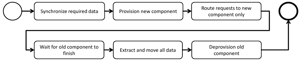
Solution: as depicted in
Figure 14, replicate and synchronize required data to be accessed by the old and the new component and provision and operate both versions concurrently. Then, instantly switch from the old to the new version of the component.
Figure 14.
Abstract Management Flow of the Move/Update without Downtime Pattern.
Figure 14.
Abstract Management Flow of the Move/Update without Downtime Pattern.
Result: because the data accessed by both components is synchronized, a consistent component behavior is ensured. The switch between both versions is done instantly. The old component is given time to finish any processing that may have been assigned to it prior to the switch. Then, additional data that was not needed directly in the beginning, for example, log information or archived data, is moved. Finally, the old component is no longer needed and can be deprovisioned.
Variations: if the managed component does not access external data, the corresponding activities in the management flow to replicate and synchronize the data accessed by the managed application component can be omitted.
Known uses: Significant efforts are being made to migrate virtual machines between multiple runtime environments without downtime [
44,
45]. [
46] gives an overview of the tasks that have to be covered and their order to achieve this.
5. Cloud Patterns and Implementation Artifacts
Patterns describe good solutions to a developer, but often they have to be implemented individually for each cloud environment used in an application. In [
18], we covered conceptually how a list of implemented application components, concrete products, and their configuration options can be annotated to patterns in order to assist and standardize these efforts. These annotations can be used to ensure a homogenization of the runtime environments. This reduces the management effort, which is one of the major cost factors of IT systems, significantly [
47].
In a similar form as architectural patterns are refined to a set of implemented software artifacts that are hosted on a standardized and restricted infrastructure, we now propose that the abstract management flows shall be refined for implemented application components. In
Section 4, we gave examples how to abstractly make an application component elastic, how to make it resilient regarding system failures, and how to move it to a different environment or update it. In this section, we show how these abstract management flows may be refined in a structured fashion through the annotation of application component implementations, middleware, hardware, and descriptions of management interfaces. We argue that this annotation will lead to a similar standardization of application management efforts as other patterns have introduced to cloud applications.
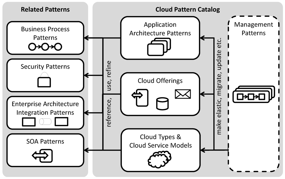
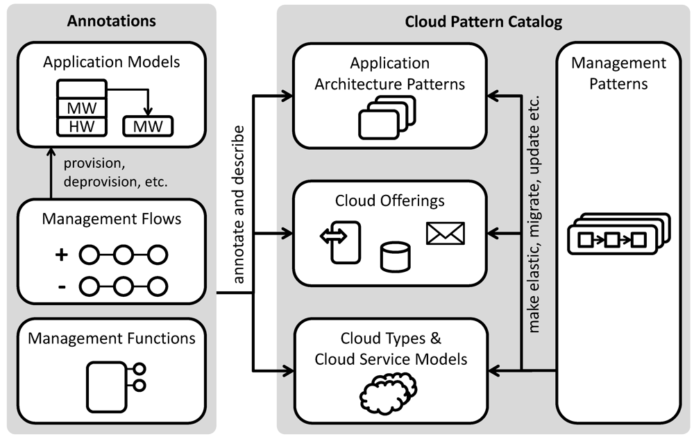
Figure 15 depicts the structure of the presented cloud pattern catalog together with proposed annotations. The new pattern class of management patterns covered in
Section 4 abstractly describes how implementations of the other pattern classes can be managed. In the following, we first describe the annotated artifacts in greater detail and then give an end-to-end example how they can guide the implementation of management patterns. We described the implementation of other patterns classes is in greater detail in [
18].
Implementation artifacts subsume application models, management functions, and management flows. Depending on the pattern class to which these artifacts are annotated, they assist the pattern instantiation to application components, cloud offering subscriptions, or management flows. Application models have been introduced by [
48,
49]. They describe the deployment dependencies among application components and used middleware. Here, we will use them to describe the dependencies among application components and cloud offerings provided by certain clouds. For example, an application component may be implemented as a Business Process Execution Language (BPEL) [
50] Process. This BPEL Process is then an entity in the application model that has a deployment dependency on a BPEL engine component. This component may then again specify a dependency on a virtual machine with an installation of Linux. Components in this model which are
provider supplied have no dependency on other components but are provided, for example, in the form of a cloud offering. [
48,
49] consider each of these components to have a standardized
component interface offering functionality to instantiate components and, in case of middleware components, to deploy other components on them. This standardized interface is used to automate the provisioning of applications modeled in the application diagram. Here, we generalize this approach and allow custom management interfaces for annotated to application components. For example, a cloud provider may offer a management interface to add users, create security credentials
etc. Management flows may then orchestrate said management functionality to automate management tasks,
i.e., those described in
Section 2.2.
Figure 15.
Organization of Cloud Patterns in the Catalog and Annotated Implementation Artifacts.
Figure 15.
Organization of Cloud Patterns in the Catalog and Annotated Implementation Artifacts.
We now give examples for annotations to a cloud type, a cloud offering, and an application component as well as show how they can be combined during the application development process.
5.1. Exemplary Annotations of a Cloud Provider
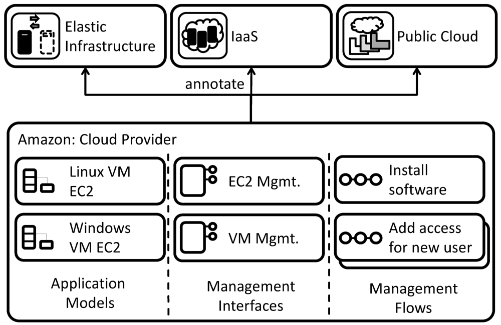
In the exemplary annotation depicted in
Figure 16, the users of the catalog wants to use Amazon EC2 as a cloud provider for the hosting of pre-configured Linux and Windows virtual machines. Further, the management functionality of these virtual machines to install software packages is made available via Web services. The provider is, therefore, described by two application models, one for the Linux and one for the Windows virtual machine. As management interfaces, the Web service interface of Amazon EC2 may be used to start and stop the virtual machines. Further, a VM management interface is provided that is offered by a Web service running on the custom virtual machine images. It offers functionality to install and uninstall software packages on instances of the virtual machines, start and stop a service, upload configuration files,
etc. The functionality of these management interfaces is used in annotated management flows to install software via the VM management interface or add access for a new user to the virtual machine.
Figure 16.
Implementations Artifacts of Amazon EC2.
Figure 16.
Implementations Artifacts of Amazon EC2.
The set of implementation artifacts associated with Amazon EC2 are annotated to the patterns provided by the EC2 cloud offering. These are: (i) the elastic infrastructure pattern, because virtual machines may be added flexibly; (ii) the Infrastructure as a Service pattern, because it is the cloud service model that Amazon follows; and (iii) the public cloud pattern as services offered by Amazon are available to everyone. Whenever a developer selects one of these annotated patterns from the catalog, these annotations are, thus, recommended to him.
5.2. Exemplary Annotations of a Cloud Offering
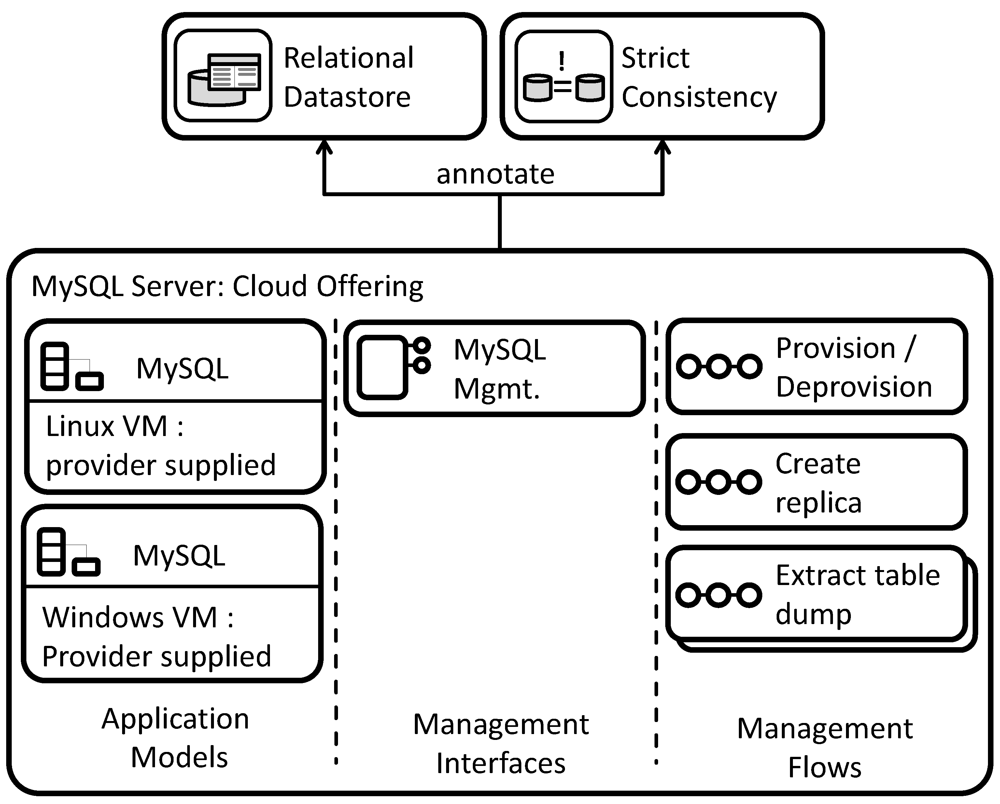
A cloud offering for a MySQL server shall be described by annotated implementation artifacts as depicted in
Figure 17. Again, multiple application models are available. In difference to the cloud provider, these application models cannot be instantiated independently but include a dependency on either a Linux or a Windows virtual machine. The MySQL offering therefore requires a virtual machine of either type providing a management interface to deploy the MySQL installation. To automate this functionality, it offers a management flow for its provisioning/deprovisioning that accesses the management interface of a running virtual machine in order to install/uninstall the MySQL server. The management functionality of MySQL itself is again encapsulated behind a management interface. This interface is further used in annotated management flows to create a replica of the MySQL server, extract a table dump,
etc.
Similar to the cloud provider, the implementation artifacts describing this cloud offering are annotated to the patterns they implement. These are (i) the relational data store pattern, which describes how the MySQL offering behaves during the access of the database; and (ii) the strict consistency pattern, which describes the data consistency model followed by the MySQL offering.
Figure 17.
Implementation Artifacts of a MySQL Cloud Offering.
Figure 17.
Implementation Artifacts of a MySQL Cloud Offering.
6. End-to-End Example for Pattern-Based Application Development and Management.
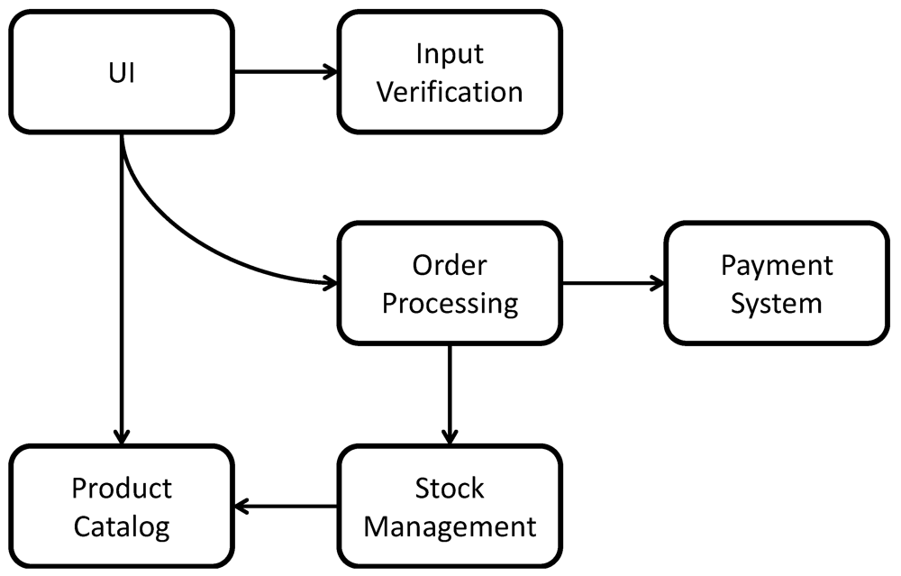
Consider the architecture diagram of a componentized application depicted in
Figure 18. It is created by an application architect and shall now be passed to an application developer to undergo the
cloud application offering process described in
Section 2.3. The used notation is similar to that of UML Component Diagrams [
51], thus, each box depicts a component and arrows show which other components are used by it. The application realizes a Web shop offering arbitrary products. Customers access the application through a web-based user interface to browse products in a product catalog. This catalog is periodically updated from a stock management component to respect item availability. Once customers decide to order an item, they are asked to input their contact and payment information. Input is first verified for consistency
i.e., to check if the zip code fits the street and city. Then, the ordering information is passed to the order processing component handling the billing and shipping process. For these tasks, the component accesses functionality of a payment system and a stock management system.
Figure 18.
Components of Web Shop Applications and their Dependencies.
Figure 18.
Components of Web Shop Applications and their Dependencies.
In the following, we show how the requirements of application components (box) and usage dependencies (arrow) on each other and on the runtime environment can be expressed through enriching the architecture diagram by pattern annotations. Based on these annotations, we discuss how application developers concretize the application components during the development phase by creating application models for each component. Finally, the annotated information is used to identify suitable management patterns during the management planning phase that are concretized by application managers using annotated implementation artifacts. In this example, we assume that the application is only developed and deployed once. Therefore, the optional application customization phase of the cloud application offering process is omitted. We show how cloud patterns may be used for expressing the requirements of the example application and the desired behavior and management of implemented application components. The architecture diagram is enriched using these patterns to guide the communication between application architects, application developers and application managers.
6.1. Requirements Management Through Pattern-Based Diagram Enrichment
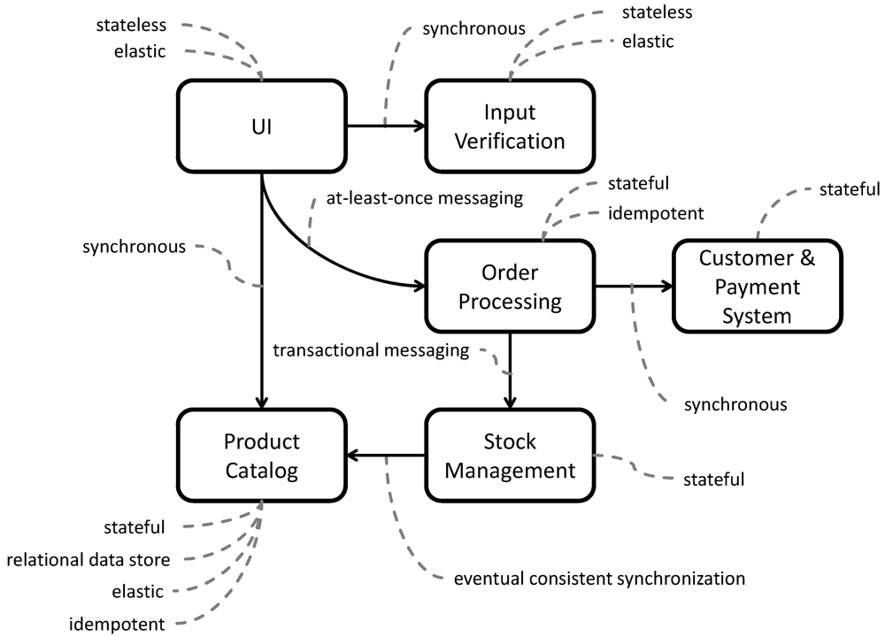
To express the behavior expected from application components and communication channels, pattern names are annotated to entities in the architecture diagram as depicted in
Figure 19. This enables application developers to identify suitable cloud offerings and middleware components that the implemented application components may use as runtime. Application components holding an internal state are characterized as implementing the
stateful component pattern, while those relying completely on external states are annotated with the
stateless component pattern. Further, the order processing component is required to be
idempotent, which means it has to be able to handle duplicate messages as it is accessed via
at-least-once-messaging. To address changing workload on the application, the application components that are needed for synchronous user interaction, UI, input verification, and product catalog, are required to be
elastic. Once the order is issued to the order processing component timely responsiveness of the application is less critical with respect to the time it requires to ship the ordered products. Finally, the product catalog reflects the items handled by the stock management component and provides it to the user interface. No real-time information is required, thus, the availability of products does not have to be reflected directly in the product catalog. The synchronization between the stock management and the product catalog is, therefore, characterized as
eventual consistent.
Figure 19.
Enriched Diagram of the Web Shop Application.
Figure 19.
Enriched Diagram of the Web Shop Application.
6.2. Concretization of Architecture Diagrams During the Development Phase
Based on the annotated pattern information, an application developer may identify potential cloud offerings and cloud providers to be used during the implementation of the application components. The pattern-based expression of requirements and desired component behavior thus enables the application architect and the application developer to use a common language and diagram format. Lengthy textual descriptions with unclear semantics are reduced. We argue that this will lead to fewer communication errors regarding requirements specification. Here, we discuss this selection of implementation artifacts and the resulting concretization of the application architecture diagram for the order processing and the product catalog component.
To implement the process ordering component, the developer decides to manage the state of individual orders in a BPEL process ensuring the implementation of the
stateful component pattern. The resulting application model is depicted in the right of
Figure 20. To address duplicate messages, he decides to implement a message filter as a Web service as suggested by the
idempotent component pattern. This message filter accepts messages send to the process ordering components and forwards it to the BPEL process. For these implementation components the application developer then requires to find an appropriate runtime environment. He identifies an application model with the Apache ODE BPEL process engine [
52], and the Apache Tomcat application server [
53], because it is annotated to both, the idempotent component and the stateful component patterns, as possible runtime. The application model then expects the availability of a Linux virtual machine. Since the order component handles business critical data, the developer decides to host it in a
private cloud. Annotated with this cloud type, he finds an application model providing a Linux virtual machine in a private cloud based on VMware [
54]. He combines this application model with the application components and the cloud offering application model to complete the application stack.
Figure 20.
Concretization of the Order Processing Component.
Figure 20.
Concretization of the Order Processing Component.
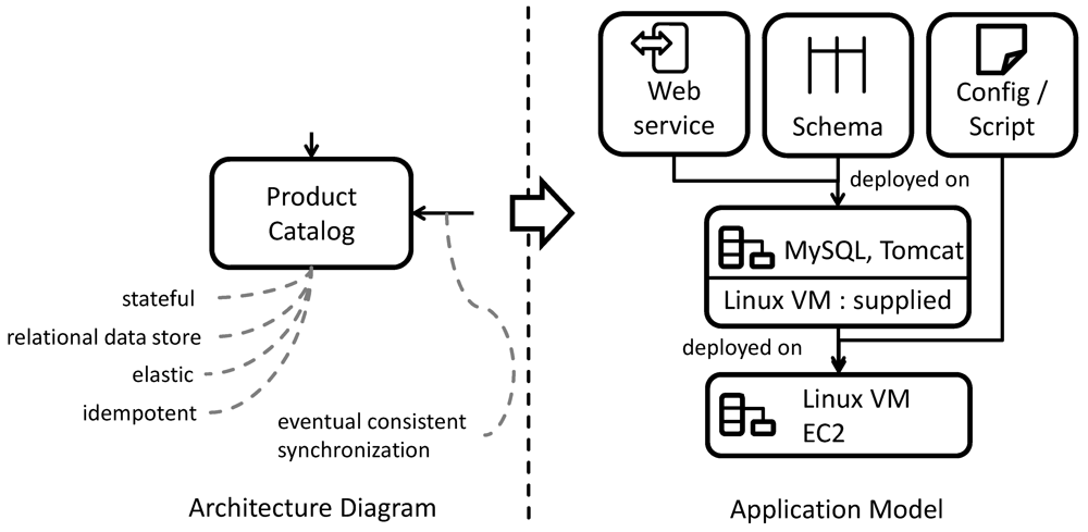
Figure 21 depicts the concretization of the product catalog component from the architecture diagram to the application model. To implement this component, the developer decides to realize it as Java Web service [
55] that accesses a MySQL database [
56]. He finds an application model for a MySQL server and an Apache Tomcat application server, a runtime for Web services, annotated to the
relational data store pattern and the
stateful component pattern. He decides to use this application model as runtime for the Web service and data base schema. As the product catalog component has to be elastic and hosts data that is publicly available, the developer further identifies a
public cloud as suitable hosting environment and finds an annotated application model for hosting the required Linux virtual machine on Amazon EC2. To implement the desired eventual consistent synchronization with the stock management component, the developer creates a shell script and configuration for the Linux virtual machine. This script is executed after certain time intervals as specified in the configuration file. It accesses the local MySQL server and issues a poll of catalog data from the stock management component. Because this synchronization is only performed after certain intervals, the desired eventual consistent synchronization is guaranteed.
Figure 21.
Concretization of the Product Catalog Component.
Figure 21.
Concretization of the Product Catalog Component.
6.3. Pattern-Based Modeling of Management Flows During the Management Planning Phase
Through the interrelation of abstract management flows with pattern-based descriptions of application architecture patterns, cloud types, cloud service models, and cloud offerings, application mangers can identify management patterns that are applicable to the created application models. Now, we briefly discuss the provisioning of application components, because extensive work exists on this subject. Further, we give detailed examples how the management patterns for component migrations described in
Section 4, can be concretized for the order processing component and the product catalog component. Again, this task is performed based on the enriched application diagram and the annotated implementation artifacts.
Provisioning of application components
Application components are provisioned through execution of provisioning management flows that are associated with them. The order in which individual provisioning flows must be executed can be obtained from dependencies between the application components. In [
57], a method is described how this order may be computed automatically. Alternatively, complete provisioning flows may be generated from the application model if an additional variability model [
49] describing component interdependencies in greater detail is also provided.
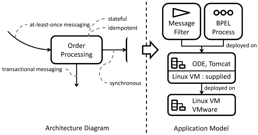
Moving the Order Processing Component with Downtime
Figure 22 depicts the deployment of the ordering processing component that is accessed through a messaging queue on the very left. The queue provides asynchronous access to the order processing component. Its application model has been identified for use in this setup through an annotation to the
at-least-once messaging pattern. We now cover the modeling of an automated management flow to move this component to a different cloud environment depicted in the center of the figure. On the right, the steps of the abstract management flow handling the move of application components with downtime are listed. The complete flow can be obtained from
Figure 12 part of
Section 4.3. The first activity in the abstract management flow is firstly to stop sending requests to the old process management component. To perform this activity in the management flow, the application manager refines this first activity to access the management interface of the messaging queue and to stop the delivery of messages. Since no more messages are processed now, the process ordering component is unavailable to the rest of the application. The second activity of the management flow (2a) waits for the running process ordering component to finish handling requests that were already assigned to it. The application manager refines this activity to periodically poll the management interface of the process engine to check the number of running process instances. Simultaneously, (2b) the new component is provisioned. This activity is handled by refining it to execute the corresponding provisioning flows for the used BPEL engine and then accessing its management interface to install the process model. In a similar fashion, the Web service handling the message filtering can be automatically setup in the new environment. When there are no more active ordering process instances running on the old process engine, the (3) process data,
i.e., information about completed instances is moved to the new ordering process component. The application manager enables this by refining this abstract activity to access the management functionality offered of the process engine in order to extract the data about the completed instances. Then, the functionality of the same interface at the new process engine is accessed to store the extracted data. When the new order processing component is ready to handle requests and all data has been moved, the next management flow activity (4a) ensures that requests are started to be send to the new component. This is enabled by accessing the management interface of the queue and starting message delivery again. At the same time, the deprovisioning management flow of the old order processing component is called to implement the abstract activity (4b) handling the deprovisioning of the old component.
Figure 22.
Steps to Move the Order Processing Component.
Figure 22.
Steps to Move the Order Processing Component.
Moving the Product Catalog Component Without Downtime
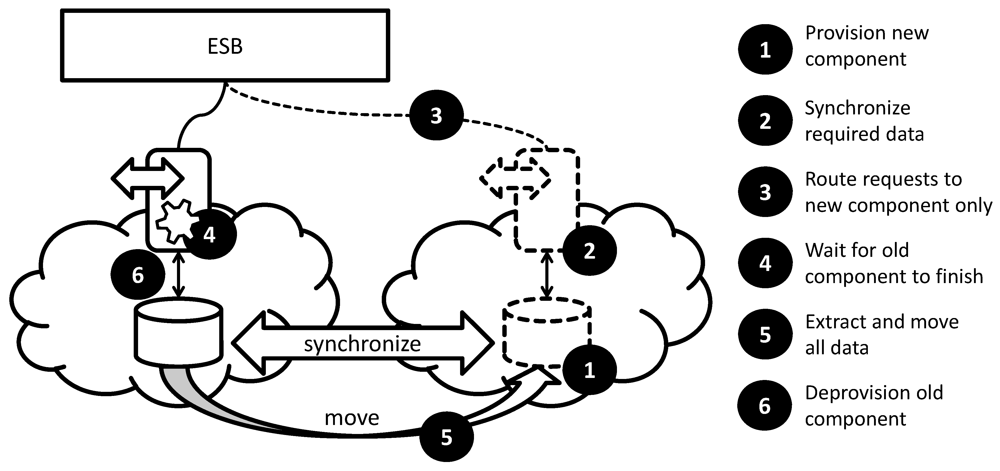
The move of the product catalog component implemented as the Web service depicted in the left of
Figure 17 shall also be automated using a management flow. The component is accessed synchronously through an enterprise service bus (ESB) [
58]. Because the product catalog is required by the user interface for application users, its migration management flow shall ensure that there is no downtime. The steps of the abstract management flow introduced in
Figure 14 of
Section 4.4 shown on the very right of
Figure 23 must therefore be concretized by the application manager. First, (1) the product catalog component is provisioned in the new environment by using its provisioning flow. Then, the application manager has to specify how (2) the required data shall be synchronized. He does so by accessing the management interface of the database residing in the old cloud environment to obtain a table dump and also models its replay to the new database component using its management interface. Because the data synchronization between the stock management component and the product catalog is eventually consistent and is also handled by a script running on the new product catalog component, this initial data replication is sufficient. The developer now refines the next abstract activity (3) to route requests to the new component by changing the configuration of the ESB using its management interface. The management flow then (4) has to wait for the old component to stop processing requests. However, the product catalog does not offer a management interface to obtain this information. The application manager, thus, refines this abstract activity to use management functionality of the cloud provider to check CPU utilization of the underlying virtual machine periodically. The following step (5) to extract and move all data can be omitted in this example, because during the remaining processing of the old component data is not created or altered. It can therefore be (6) deprovisioned by including its corresponding management flow.
Figure 23.
Steps to Move the Product Catalog Component.
Figure 23.
Steps to Move the Product Catalog Component.
6.4. Triggering of Automated Management Flows
In [
59], we present a framework handling the event-based execution of provisioning and deprovisioning flows annotated to application components. Based on application model events can be specified, which are generated by each component or by the user of the application. Additionally, for each application component it can be specified if it should be provisioned or deprovisioned if a specific event was observed. For example, a queue can throw an event when a certain threshold of messages stored in it is exceeded. The necessary provisioning and deprovisioning flows are then triggered by the framework through iteration of the application components in the application model. Those, whose provisioning or deprovisioning flows are triggered by this event are then added or removed from the application respectively. In scope of the queue example, the framework can, therefore, ensure that additional components are provisioned to handle messages in case the queue is filling up. The refined automated management flows, proposed by this paper, seamlessly integrate into this framework through their correlation to events generated by users and application components to specify under which conditions they shall be executed.
7. Summary and Outlook
We have seen how the pattern catalog may guide application developers during the creation of application components. The patterns implemented by individual application components also guided the application managers during the identification of management patterns that he could use to manage the application component. We have defined such abstract management flows in a pattern format to handle elasticity, resiliency, and for moving application components between different environments or updating them to a new version. Using the proposed pattern catalog and annotated implementation artifacts, we have further shown how these abstract management flows could be refined for different components of an exemplary web shop application. Future use of patterns in architecture diagrams will have to be further refined to handle a larger catalog of patterns and have to be integrated into architecture modeling tools. An extension of architecture modeling languages, such xADL [
60], could be one solution. The general challenge that needs to be addressed is the creation of a composition language to connect the icons of architectural patterns in a structured and well-defined manner. To extend tool support, patterns should further be associated with properties of the application that they enable, for example, high-availability, privacy,
etc. With an increasing size of the catalog, such annotations provide an easier accessibility of the patterns.
A limitation of the presented approach is that the management flows currently consider isolated application components. While such isolated management of application components can be helpful during the runtime management of the application, considering the complete application would be even more powerful. For example, based on the architectural diagram of the example Web shop application seen in
Figure 18 of
Section 6 management tasks may be automated for the overall application as well. Conceptually, this would result in a management flow that executes the individual management flows of application components in a particular order. This order can likely be determined automatically by a graph-analysis of the dependencies expressed in the application architectural diagram. Therefore, future research will investigate how the dependencies between application components can be evaluated automatically to compose individual management flows of application components into management flows handling the complete application. In [
57] such computations have already been investigated based on similar architecture diagrams and descriptions of variability. However, these models only consider deployment dependencies of application components on middleware and hardware to compute the order of provisioning tasks. To incorporate the links of architecture diagrams, these models and corresponding algorithms need to be extended respectively.
Another limitation is that individual components are refined to use separate middleware and hardware stacks, thus, each application component is individually combined with cloud offerings by the application developer. However, in practice, application components often share middleware and hardware due to performance and licensing issues. In [
61], we proposed a method, how application architecture diagrams can be used to optimize the assignment of application components to different middleware installations, virtual machines, and clouds. The above mentioned management flows considering the complete application, therefore, have to respect the impact of shared middleware, hardware, and cloud offerings as well. The challenge to merge redundant middleware and hardware also arises if outsourced IT resources are moved back into a company or two companies merge. Therefore, approaches targeting these challenges may be applicable in the domain of pattern-based development and management of cloud applications. Recently, [
62] started to capture these concepts.
