Multi-Topology Routing Algorithms in SDN-Based Space Information Networks


Science and Technology on Complex Electronic System Simulation Laboratory, Space Engineering University, Beijing 101416, China
*
Author to whom correspondence should be addressed.
Future Internet 2019, 11(1), 15; https://doi.org/10.3390/fi11010015
Submission received: 2 December 2018
/
Revised: 27 December 2018
/
Accepted: 8 January 2019
/
Published: 12 January 2019
Abstract
:Aiming at the complex structure of the space information networks (SIN) and the dynamic change of network topology, in order to design an efficient routing strategy, this paper establishes a SIN management architecture based on Software-defined Networking (SDN). A routing algorithm flow of the spatial information network based on a snapshot sequence is designed. For different spatial tasks with different Quality of Service (QoS) requirements, the concept of integrated link weight is proposed. The Warshall–Floyd algorithm is used to design the optimal routing strategy. A Task-oriented Bandwidth Resource Allocation (TBA) algorithm is proposed for multiple spatial tasks in the same link. Simulation results show that the algorithm can effectively guarantee the priority transmission of important tasks and avoid the unnecessary waste of bandwidth resources.
1. Introduction
The space information networks (SIN) is a network system that acquires, transmits, and processes spatial information in real time using various spatial platforms (such as synchronous satellites or medium and low-orbiting satellites, stratospheric balloons and manned or unmanned aerial vehicles) as carriers [1]. Because of its unique spatial location advantages, compared with the ground network, SIN plays an irreplaceable role in earth observation, emergency communications, air transport, space measurement and control and the expansion of national strategic interests, and has gradually become a high frontier of national strategic interests [2]. Because of the wide coverage of the SIN, remote users often cannot communicate directly and need a multi-hop relay to transmit data. Therefore, in order to improve the efficiency of the use of spatial information resources and complete different types of spatial tasks, it is necessary to design efficient routing strategies.
The SIN mainly has the following problems in the design of routing algorithms: (1) Medium and low-orbit satellites move very fast, which leads to frequent dynamic changes of the SIN topology and inter-satellite links. (2) Compared with the terrestrial network, the propagation delay of the space network part is large, and the bandwidth resources are very limited. (3) Because the design of satellite-based equipment is different from that of ground-based equipment, the power, size, and weight of satellite-based equipment are strictly limited, which affects the operation and storage capacity of satellite-based equipment. Therefore, the on-board routing algorithm of the SIN should be relatively simple. The difficulties of routing algorithms in the SIN mainly come from the spatial network, and the routing algorithms in terrestrial networks have been relatively mature [3].
At present, there are few researches on routing algorithms for the SIN. According to different solutions, these algorithms can be divided into two categories, spatial virtualization method and temporal virtualization method [4].
The method of spatial virtualization is to virtualize the area covered by the whole satellite network or to virtualize the constellation of satellites by using the structure characteristics of the satellite network itself. The idea of spatial virtualization routing algorithm is to divide the ground area covered by satellite into several blocks, and then assign each region an independent logical address. The logical location of the satellite is determined by the logical address. With the operation of the satellite, the logical location is updated periodically. Such methods require relatively high on-satellite processing capacity, and may not be able to obtain optimal routing because of the use of local information for routing calculations [5].
Time virtualization mainly uses the predictability and periodicity of satellite motion to divide the whole operation period of the SIN into several time slices in a certain way and virtualize the topology of SIN from time. Therefore, the topology of the network can be approximately considered to be fixed in each time segment, so static topology can be used for routing calculation in advance.
The snapshot sequence (SSS) algorithm proposed by Gounder et al. [6], the Virtual Path (VP) algorithm proposed by Werner, and the Finite State Machine Algorithm (FSA) algorithm proposed by Hong et al. [7] are typical routing algorithm under the time virtualization idea [8].
Among them, the SSS algorithm proposed by Gounder et al. is the most feasible and simple routing algorithm for the SIN. The algorithm divides the dynamic topology of the SIN into several discrete static topologies in a period, each of which is called a snapshot. When the link of the SIN changes, that is, when the network topology changes, a new snapshot is produced, then the periodic topology of the SIN can be transformed into a set of topology snapshot cycle, and the cycle is the operation cycle of SIN.
In this paper, we propose a routing algorithm based on snapshot sequence. However, the number of static topologies increases dramatically with the increase of network size. As a complex network, the number of nodes in the SIN is very large, which overburdens the computing and storage capacity of onboard devices. In addition, the traditional satellite network control architecture cannot effectively recalculate the routing when the satellite link fails or the load is too heavy. Therefore, this paper first proposes a SIN management framework based on SDN. The routing calculation, configuration generation and resource management of the whole network are all handled by the SIN resource scheduling and management center and controller on the ground, which cannot only reduce the burden of satellite nodes, but also benefit the overall unified management.
The existing routing algorithms based on SDN can be divided into four categories, a routing algorithm based on QoS, a routing algorithm based on energy aware, a routing algorithm based on load balancing, and a routing algorithm based on application/service aware [9].
QoS refers to the ability to provide better services for specific businesses in heterogeneous networks. The goal of QoS is to improve priority services for different businesses. Intuitively speaking, QoS represents meeting some specific needs of users, such as transmission rate, waiting time, error rate, packet loss rate, etc. In order to improve the efficiency of the SIN and satisfy the transmission requirements of different spatial tasks, this paper studies the multi-topology routing algorithm based on QoS routing algorithm. By calculating the link comprehensive weight of SIN, the Warshall–Floyd algorithm is used to select the best transmission path [10]. Based on the selection of transmission links, this paper proposes a TBA algorithm to ensure the priority transmission of special users and important tasks.
The main contributions of this paper are as follows.
- (1)
- The SIN management architecture based on SDN is established, which realizes the unified management of spatial resources and provides sufficient storage and computing space for the routing algorithm of the SIN based on snapshot sequence.
- (2)
- On this basis, according to different space tasks’ QoS requirements, a method of calculating integrated link weights of the SIN is designed, so that space tasks with different QoS requirements can get their optimal routing strategy.
- (3)
- In view of the transmission of multiple space tasks on the same link, the proposed TBA algorithm can effectively guarantee the timely transmission of important tasks, thereby improving the quality of service of the SIN.
The rest chapters of this article are arranged as follows: Section 2 firstly introduces the related concepts of SDN, and analyzes the advantages of the SIN based on SDN. Section 3 establishes SIN management framework based on SDN, and on this basis, designs a snapshot sequence-based SIN routing algorithm process. Section 4 designs the multi-topology routing algorithm, calculates the initial link weight and integrated link weight of the SIN, and proposes a TBA algorithm. Section 5 firstly designs the optimal routing strategy by using Warshall–Floyd algorithm on the basis of Section 4.2, and then simulates the TBA algorithm proposed in Section 4.3. Section 6 discusses and summarizes the full text.
2. Related Work
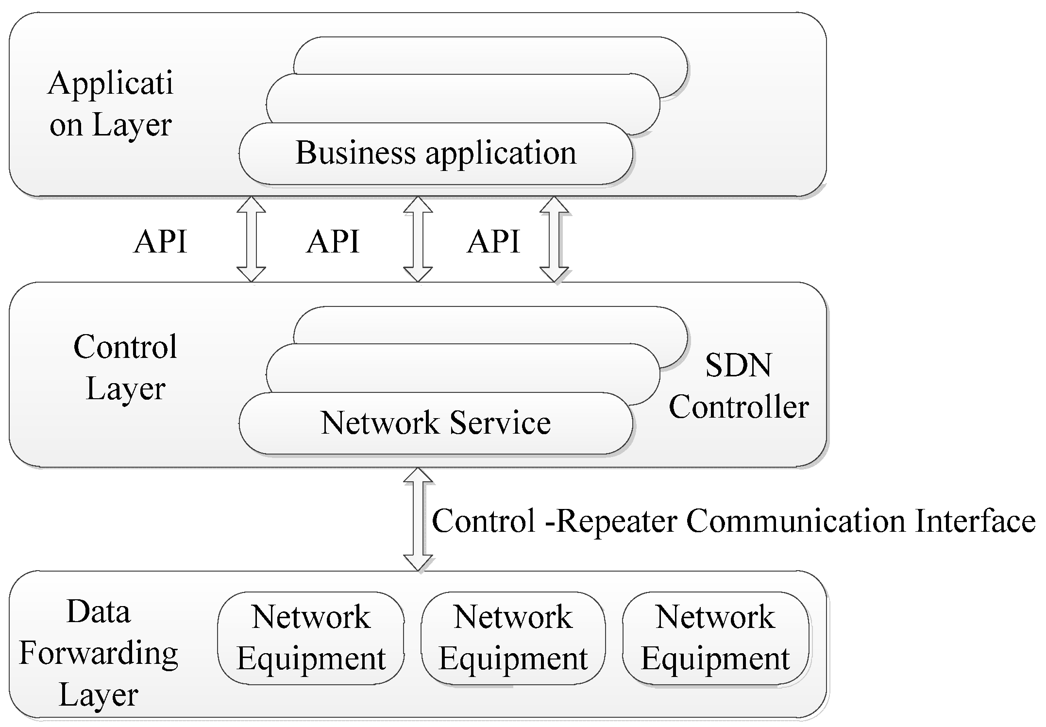
SDN is a network architecture that decouples the control functions in the network from the physical forwarding device. Its control plane implements logical centralized control of the data forwarding device by introducing a centralized controller, while the data forwarding device is only responsible for performance data processing and forwarding. At the same time, its application layer can shield the difference of the underlying physical network hardware devices, and realize the network architecture of specific needs through application programming [11].
The design architecture of SDN mainly includes a data forwarding layer, control layer, an application layer, and the interface between adjacent planes [12]. The SDN structure is shown in Figure 1.
- (1)
- Data forwarding layer. Data forwarding layer is composed of the underlying forwarding device of the network. Data forwarding layer is responsible for data processing, forwarding and status collection based on the traffic flow table, and executes the fast forwarding of data according to the instructions issued by the control layer.
- (2)
- Control layer. Control layer is responsible for dealing with the abstract information of the data forwarding plane resources. On the one hand, using the southbound interface, the control layer can control the forwarding behavior of the underlying network devices, abstract the resources of the underlying network devices, obtain the information of the underlying network devices, and then generate a global network Abstract view. On the other hand, a control layer provides the abstract model of the underlying network to the upper network application through the northward interface.
- (3)
- Application layer. Application layer mainly includes network applications for various network services in the control layer. It is mainly responsible for managing and controlling the network forwarding/processing strategies for applications [13].
At present, some scholars at home and abroad have proposed to apply SDN technology to the SIN, mainly focusing on the architecture and controller deployment strategy. Document [14] proposes an OpenSAN model, which is a typical SDN-based satellite network structure. Document [15] presents a space integrated multi-layer satellite communication network based on software definition network and virtualization of network functions. Documents [16,17] focus on the controller deployment of the SIN based on SDN. Current research lacks specific analysis of the SIN routing algorithm based on SDN.
Applying SDN to the SIN has the following advantages:
- (1)
- The operation of the SIN has periodicity and regularity. SDN controller can make full use of these information to calculate and manage the network.
- (2)
- Satellite nodes in the SIN run fast, so their topology is highly dynamic. According to this topological information, the SDN controller can perform real-time and efficient operation in order to make the network run efficiently and increase the stability of the network.
- (3)
- SDN network architecture is a centralized network, and SDN controller monitors and manages the whole network uniformly. Therefore, combined with the idea of SDN, the ground SDN controller has the information and real-time data flow of all satellite nodes in the whole network. In this way, the SDN controller can find the optimal transmission path according to the data flow distribution of the whole network, which is conducive to saving the bandwidth resources of satellite communication and avoiding the cost.
- (4)
- In a traditional distributed network, when a new network protocol is deployed or a new algorithm is verified, each server needs to be updated, so that the labor cycle and human resources are enormous. However, combined with the SDN idea, only need to carry out protocol deployment or algorithm migration in the control layer of the network, and then unified calculation by the controller. The network nodes only need to execute the instructions of the controller to verify the performance of the algorithm or protocol. This makes the research and verification of communication network technology more convenient and fast [18,19].
- (5)
- Data plane network equipment in SDN only realizes forwarding function, which can simplify the design of network equipment, facilitate the startup and maintenance of equipment, reduce the cost of equipment, and bring great convenience to on-board equipment.
- (6)
- The global network view of the controller and the open northbound interface in SDN can realize automatic and rapid configuration and response for different dynamic requirements of tasks, and meet the dynamic and fast networking requirements of the SIN.
3. SDN-Based SIN Management Architecture
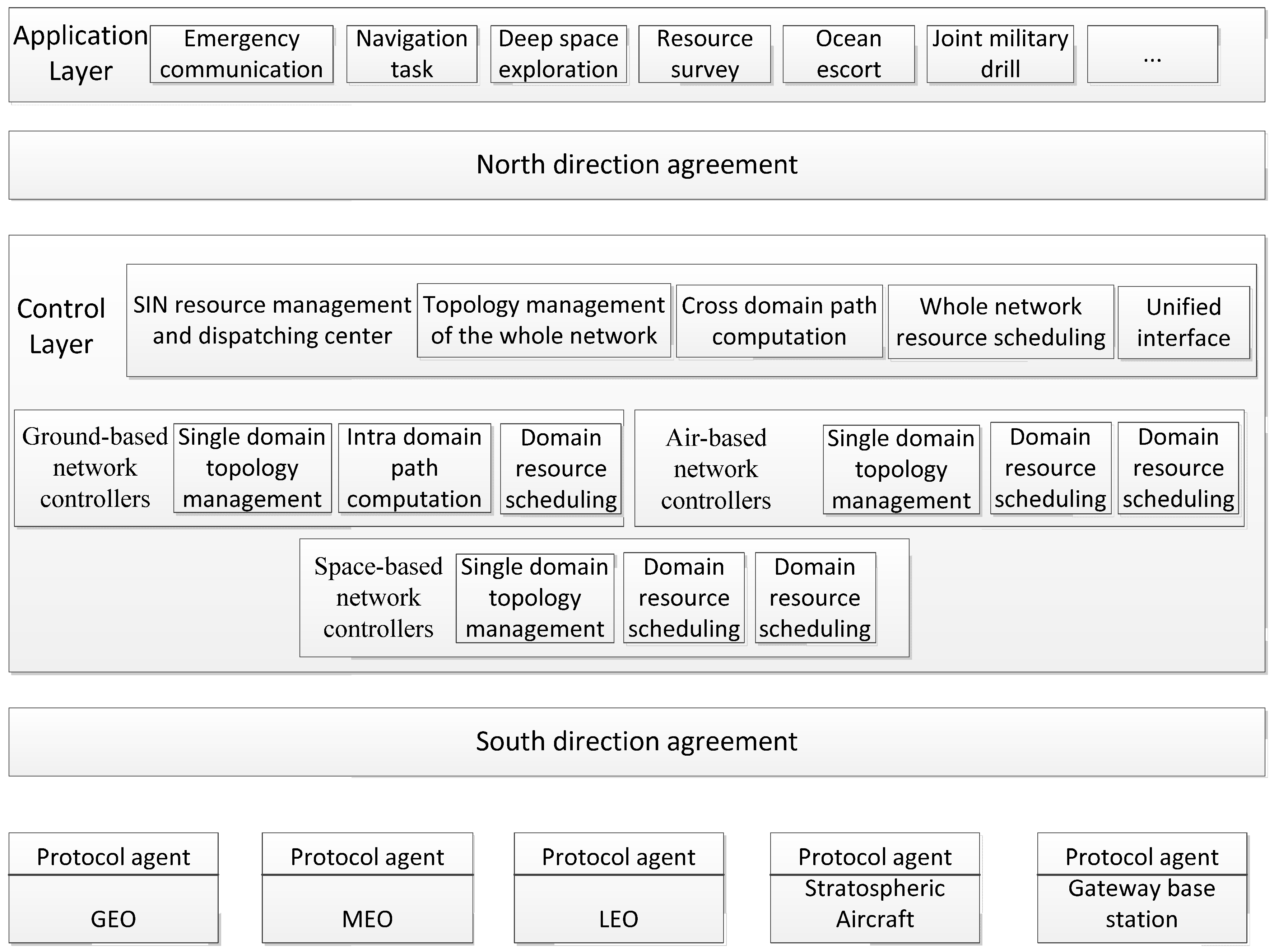
This paper first establishes a SDN-based SIN management architecture. Based on SDN, this paper divides the architecture of the SIN into three parts: space-based network, air-based network and ground-based network. Three kinds of network controllers, space-based network controllers, air-based network controllers and ground-based network controllers, are established on the ground to control space-based network, air-based network, and ground-based network respectively. At the same time, according to the geographical area, the ground-based network, air-based network, and space-based network can be further divided into several domains, each domain is controlled by a single domain controller. Space-based network is mainly composed of a variety of satellites with different orbits. The satellites from far to near are geostationary orbit satellites (GEO), medium orbit satellites (MEO), and low orbit satellites (LEO). The air based network is mainly composed of stratospheric airships, balloons, manned or pilotless aircraft. The ground-based network part is mainly composed of gateway control center, large gateway station and ground public communication network [20]. A SIN resource management and dispatching center is established on the ground, which is responsible for the link calculation of the whole SIN and the control and allocation of the whole network resources. The architecture of the SIN management based on SDN is shown in Figure 2 [21].
SDN-based SIN management architecture is divided into three layers: application layer, control layer, and infrastructure layer. The top layer is the application layer, which refers to a series of tasks such as emergency communication and deep space exploration completed by the SIN. At the bottom is the infrastructure layer, which includes satellites in different orbits, stratospheric vehicles, gateway base stations and other facilities serving the SIN. In the middle is the control layer, which is composed of network controller and the SIN resource management and scheduling center.
In the control layer, the single-domain controller collects topology information of each node in the domain. When the intra-domain traffic arrives, the single-domain controller calculates the intra-domain links, controls the nodes by sending down the flow table, and realizes path building and traffic processing. The SIN resource management and scheduling center is responsible for the control and allocation of the whole network resources. It obtains the topological resources of each domain from the single domain controller and establishes the whole network topology. When cross domain resources come, SIN resource management and scheduling center is responsible for cross domain routing computation and cross domain transmission. In addition, due to the heterogeneity of different inter-domain networks, SIN resource management and scheduling center is also responsible for the unification of heterogeneous device interfaces to achieve cross-domain interconnection of heterogeneous devices.
In the SIN management architecture based on SDN, north-oriented and south-Oriented protocols play an important role. North-oriented protocol is a series of interfaces between application layer and control layer. There is no unified standard for its interface protocol. Therefore, the control layer provides many extensible API interfaces for different users in the application layer, each API interface corresponds to a corresponding application, so the control architecture can implement a variety of application services. A typical southbound protocol is OpenFlow [22], which is responsible for the interaction between the control layer and the underlying implementation switches to complete the forwarding of infrastructure layer data. In the OpenFlow protocol, an OpenFlow switch can connect multiple network controllers, but at the same time, only one controller has control over it, and other controllers have read-only function. In the SDN-based SIN management architecture, all switches in each single domain can only be managed by its single domain controller.
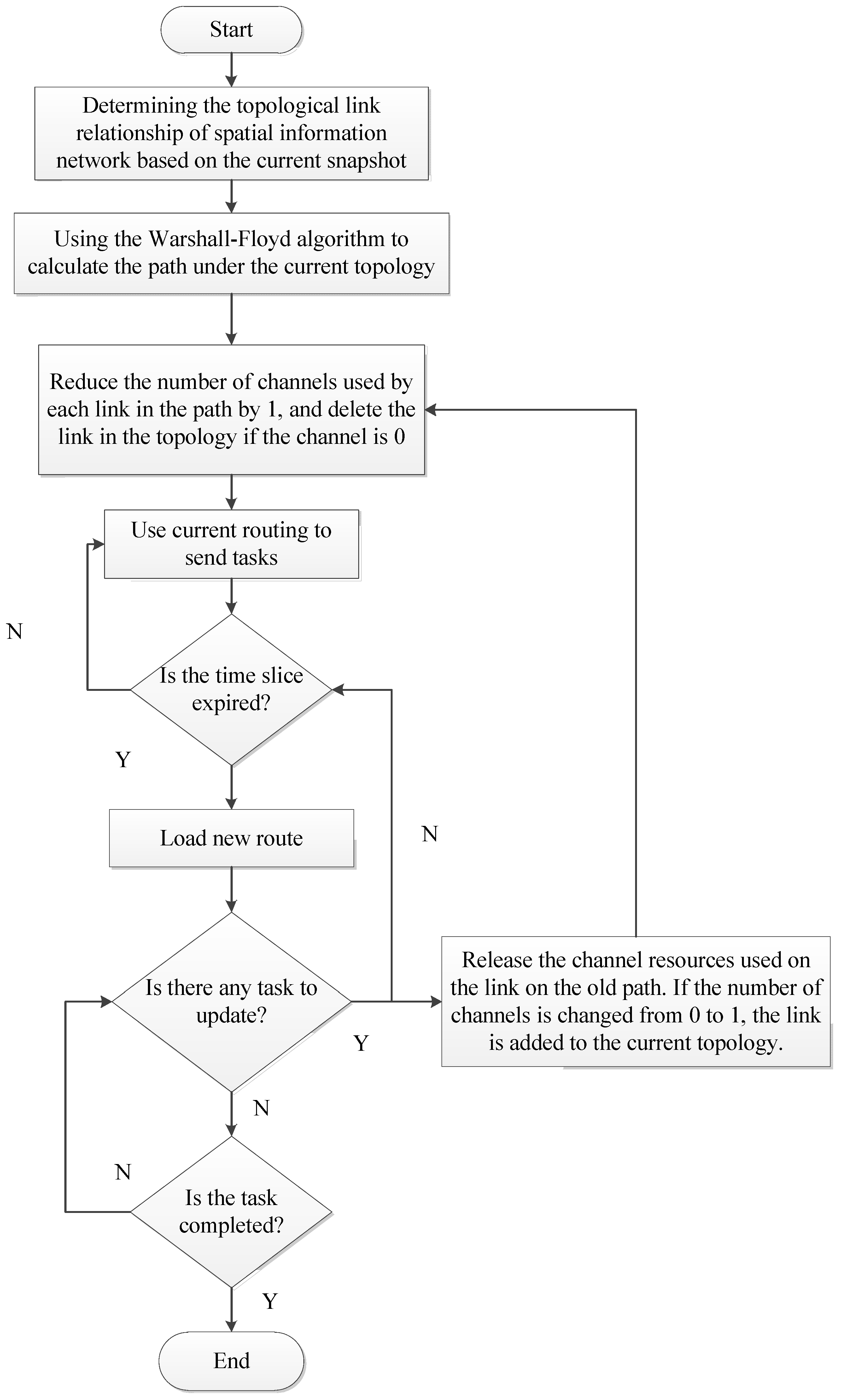
Based on the establishment of SDN-based SIN management architecture, the routing algorithm flow of spatial information network based on a snapshot sequence is designed as shown in Figure 3.
Let the topological period of the SIN be T, and the topological structure of the network after time T is consistent with that before. The cycle T is divided into a series of time slices , … . The time slot of the time slice is small enough, so it can be assumed that the slot is a static topological structure, and the topological structure only switches at the time point. After time T, the network repeats its original state. Thus, the whole dynamic network topology is divided into several static topologies. We only need to analyze the static routing in each slot and the routing handover strategy in the link handover [23].
When the time slice is switched, due to the high dynamic characteristics of SIN nodes, the link changes, and the routing needs to be recalculated. If the recalculated routing strategy is different from the original, only the original transmission link is cut off, and then a new transmission link is re-established, which requires a certain delay. The original data transmission will be interrupted, which is intolerable for tasks with high delay requirements, which is not tolerated for the task with high delay requirements. Therefore, a soft handoff strategy is needed. When two time slices are switched, the original transmission path is cut off after the new routing strategy is established and run to avoid the interruption of data transmission.
4. Multi Topology Routing Algorithm
In the SIN, different spatial tasks have different QoS requirements. Spatial tasks can be divided into three categories:
- (1)
- Delay sensitive service. Such services mainly include language services, real-time video interactive services, which allow a certain packet loss rate, but have certain requirements for transmission delay and delay jitter.
- (2)
- Throughput sensitive service. Such services mainly include a large number of data file transfer services. They do not require real-time performance, but they require a certain bandwidth guarantee. Usually, the packet loss rate is required to maintain a constant transmission rate.
- (3)
- Best effort service. Such services have no special requirements for delay, bandwidth, packet loss rate and so on [24].
4.1. Initial Link Weight
According to the above classification of spatial tasks, QoS optimization objectives usually include the following: dedicated bandwidth, end-to-end delay, delay jitter and packet loss rate. According to the above optimization objectives, E is used to represent the initial link weight, s and d are used to represent the source and destination nodes of a path respectively, (i, j) represents a link between node and destination node, from node i to node j, band (i, j) represents the residual bandwidth of the link (i, j), delay (i, j) represents the end-to-end delay of link (i, j), jitter (i, j) represents the delay jitter of link (i, j), loss (i, j) represents the packet loss rate of the link (i, j). B, D, J and L respectively represent the requirements of spatial tasks on residual bandwidth, end-to-end delay, delay jitter and packet loss rate. The end-to-end delay consists of four parts: propagation delay on the link, processing delay on the node, transmission delay on the node port and queuing delay on the node. The remaining bandwidth, end-to-end delay, delay jitter and packet loss rate constraint formulas are as follows:
The initial link weight is calculated according to the business requirement, and the initial link weight calculation model is:
The constraints of various performance parameters are
represent the calculation coefficients of residual bandwidth, end-to-end delay, delay jitter and packet loss rate respectively, and the initial link weight formula is as follows.
Here, .
The SIN is large in scale and complex in structure. Different tasks have different attributes, different requirements for link attributes and different parameter settings. Therefore, the initial link weights for different tasks are different.
4.2. Integrated Link Weight
After assigning the initial link weight to the link in the SIN, the routing algorithms is executed, the following situations may occur: although the selected link is of high quality, the two ends of the link are already performing other tasks and have a high degree of busyness, which will cause the burden of space nodes to increase, resulting in poor transmission quality and even failure of tasks. Therefore, in order to ensure the transmission efficiency of the SIN, a variable N is proposed to describe the busy degree of the SIN nodes, which is defined as the ratio of the acceptance rate of the spatial node (the rate of receiving packets) to the transmission rate of the spatial node (the rate of sending packets). The transmission state of space node is described according to the situation of receiving data packets by space node. Sending data packets will reduce the busy degree of the space node, while receiving data packets will increase the busy degree of the space node. Therefore, the larger the value of N, the larger the busyness of the spatial node, the busy the spatial node, and the weaker the ability to accept the load, the smaller the value of N, the stronger the ability of the spatial node to accept the load [25].
Let N represents the node busy degree of a segment, and the formula of node busy degree is
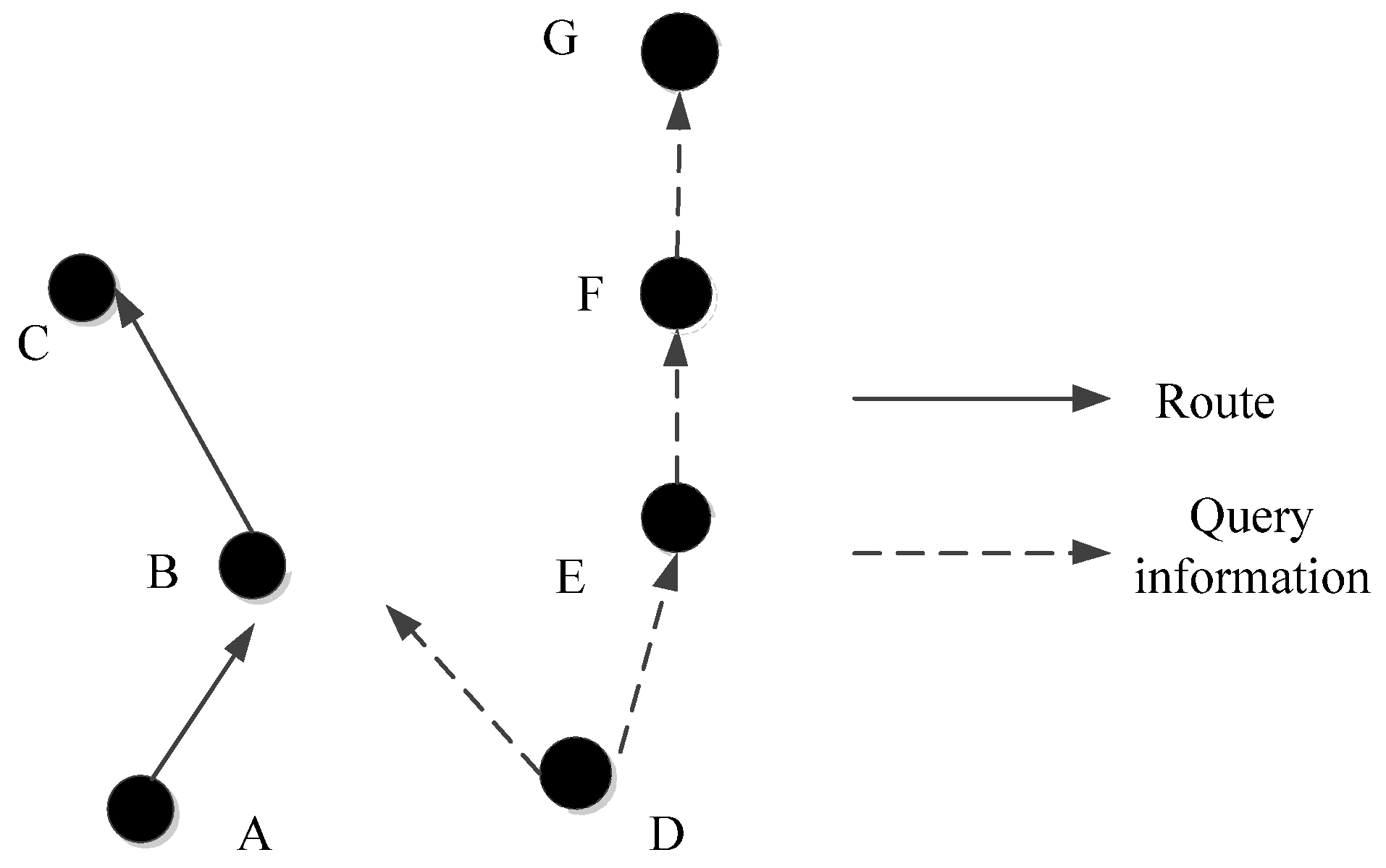
In addition, when the nodes in the SIN are busy, after receiving the new routing query message, according to their busy degree, the nodes set a certain delay forwarding routing query time to reduce the possibility of competition and congestion. The delay forwarding routing query time is shown in Table 1.
The schematic diagram of the SIN nodes using delayed forwarding routing strategy is shown in Figure 4.
When the routing from point A to point C is established, if point D wants to establish a routing to point G, when the routing query is initiated, the routing from point D to point E will be established prior to the routing from point B under the same initial link weight of the BD link and the ED link.
Let IIW to indicate the comprehensive transmission weight of the link, t represents the delay forwarding routing query time of neighbor nodes. respectively represent the calculation coefficient of the initial weight of the link, the busyness of the spatial node, and the delayed forwarding route query time. The formula for calculating the integrated link weights is
4.3. TBA Algorithm
As a complex system, SIN have different spatial tasks running at the same time. Therefore, we need to study the routing algorithms when multitasking is performed simultaneously.
First, choose the shortest path. When different priority tasks have a common shortest path, the higher priority task flow takes the shortest path first. Low priority task flow depends on the shortest path: (1) When the shortest path has available bandwidth, it should choose the shortest path, otherwise it will take the sub shortest path. (2) The scheduling is performed in real time during the running process to ensure that different tasks meet the QoS requirements.
But there are also possible special cases, that is, in the same node or link only one, different users of different tasks at the same time in a link transmission, and the total link bandwidth does not meet all the tasks of the application bandwidth. At this point, the bandwidth allocation strategy needs to be determined according to the priority of different tasks, so that different levels of tasks negotiate the use of bandwidth resources. Therefore, this paper proposes a TBA algorithm [26].
First, we propose a concept of bandwidth resource allocation factor. There are users with different priorities in the SIN, which are divided into ordinary users and special users. At the same time, there are spatial tasks with different priorities. Therefore, in the design of the SIN, it is necessary to consider user priority and task priority to determine the allocation factor of bandwidth resources.
User priority is defined as follows.
Task priority mainly depends on the importance of the task, maximum delay tolerance and other parameters. ’s priority is defined as follows.
Here, represents the importance of , represents the maximum end-to-end delay allowed by , represents the maximum time delay jitter of , represents the maximum packet loss rate allowed by . That is, the higher the importance of the task, the smaller the maximum end-to-end delay and delay jitter allowed, and the smaller the maximum allowed packet loss rate, the higher the priority of the task.
In summary, the bandwidth resource allocation factor of spatial information tasks can be defined as the product of user priority and task priority, and the expression is as follows:
Suppose there are three spatial tasks on a selected link: , , . Task assignment factor is , s and d represent the source node and the destination node of a path respectively, the path is represented as path, define as the available bandwidth of each hop on the selected path of the routing algorithm, is the available bandwidth of hop r in the path. The path bandwidth allocated by the system to is:
Here, represents the bandwidth allocated to the r-hop of the selected path of . Define the bandwidth set for application:
Here, indicates the bandwidth requested by the in the r-hop of the path. Similarly, the allocation bandwidth and application bandwidth of and can be obtained. When the link bandwidth does not meet the bandwidth requirements of all tasks, you need to allocate bandwidth in different proportions according to the size of different task allocation factors.
Of course, on the r-hop link, the sum of the allocated bandwidth of the three tasks cannot exceed the total bandwidth of the r-hop, that is:
In addition, there is a certain minimum bandwidth requirement for delay-sensitive services, throughput-sensitive services and best-effort services. If the minimum bandwidth is not satisfied, the transmission of the task is terminated and the transmission bandwidth of the remaining tasks is reallocated. The link condition is detected in real time. When the link bandwidth meets its minimum requirements, the task is re-transmitted. The minimum path bandwidth required by is:
where denotes the minimum bandwidth required by in r hop. Similarly, the minimum path bandwidth of , can be obtained.
Suppose that the order of arrival of the three tasks is , , , when arrives, the and are should be checked first. If the bandwidth applied by and is less than the available bandwidth, it is proved that the link has available bandwidth. Then determine whether the remaining bandwidth meets the request of , if it is satisfied, the bandwidth it requests is provided, if it is not satisfied, the allocation bandwidth of all three tasks is verified to be greater than the minimum bandwidth, and then the bandwidth resources are allocated according to the bandwidth resource allocation factor. If the bandwidth requested by and is larger than the available bandwidth, the allocation bandwidth of all three tasks is verified directly to be larger than their minimum bandwidth, and then the bandwidth resources are allocated according to the bandwidth allocation factor [27].
The basic flow of TBA Algorithm is shown in Algorithm 1:
| Algorithm 1. TBA Algorithm |
| Input: The path has been selected; Output: Bandwidth resource allocation strategy in the SIN; |
| 1: The bandwidth resource allocation factor of , , are obtained; 2: for New arrives 3: if 4: ; 5: if 6: ; 7: else if 8: Calculate , , according to Formulas (15) and (16). Reallocating bandwidth resources; 9: if , , 10: , , ; 11: else if or or 12: To terminate the transmission of the task that is not satisfied, and recalculate the bandwidth allocation factor for the rest of the tasks; 13: end if 14: end if 15: else if 16: Repeat step 8–12; 17: end if 18: end for |
5. Design and Experiment Results
5.1. Optimal Routing Strategy
After obtaining the comprehensive weights of each link in the SIN, the optimal routing strategy of the SIN is analyzed. The classical shortest path algorithms mainly include Warshall–Floyd algorithm and Dijkstra algorithm. Dijkstra algorithm mainly calculates the shortest path from a single source to multiple target nodes. It is mainly used when the nodes and links are not fully understood. Warshall–Floyd algorithm can be used to calculate the shortest path of multiple sources, and is more suitable for the situation that the whole network has been mastered. Therefore, this paper intends to use Warshall–Floyd algorithm. The Warshall–Floyd algorithm calculates the optimal path between two nodes as follows:
- (1)
- The graph is , and the vertex set is , calculate the integrated link weight fee of each side of G, where represents the weight of edge , and if and are not adjacent, then .
- (2)
- The basic idea of dynamic programming algorithm is used. For any vertex , the shortest path from vertex to vertex passes through vertex or without vertex . Let be the shortest distance from vertex to , be the shortest distance from vertex to , is the shortest distance from vertex to vertex without vertex .
- (3)
- If , then .
- (4)
- Repeat (3) to search all vertices , is the shortest distance from vertex to vertex [28].
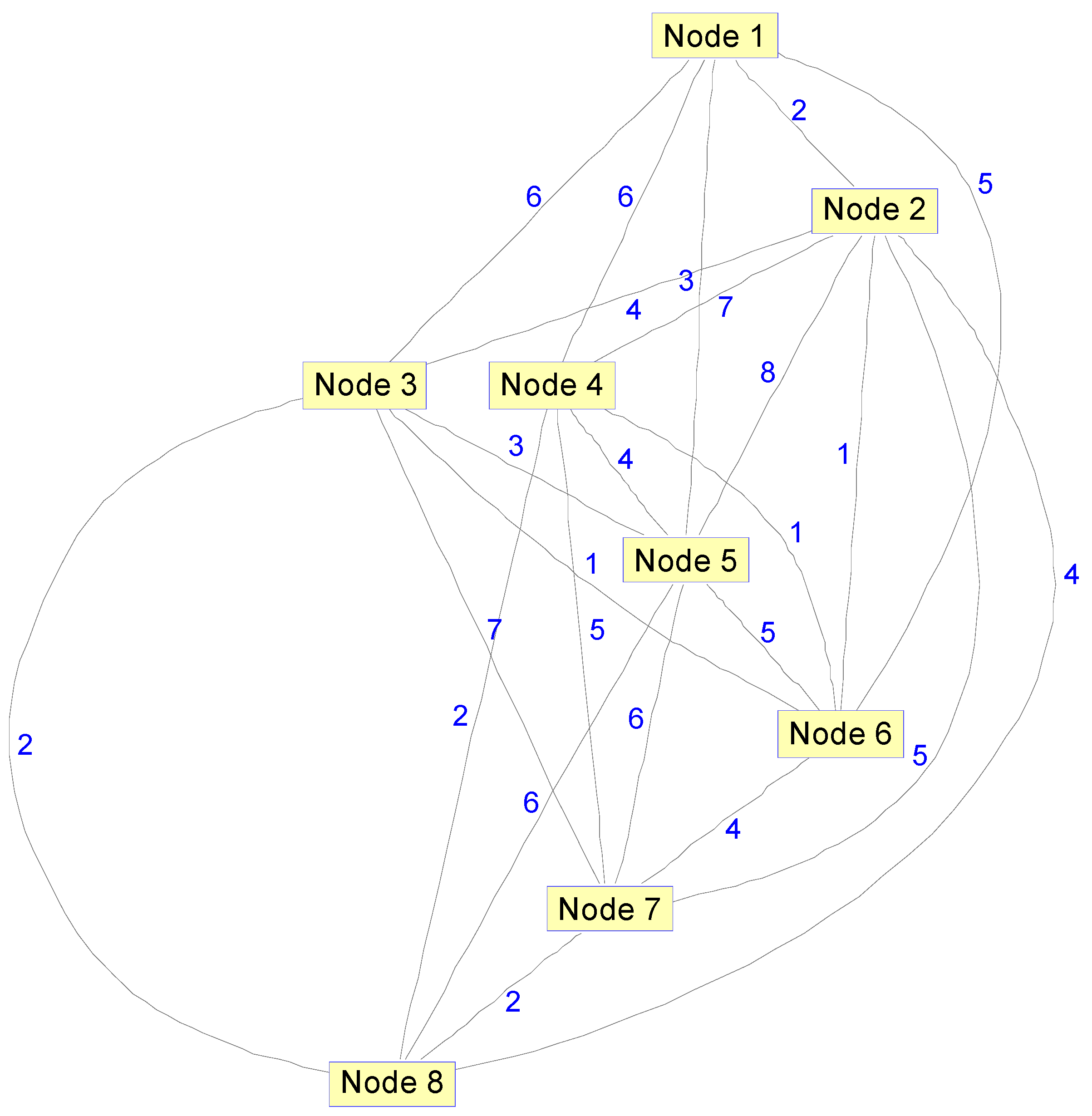
Suppose there are eight nodes in the SIN. For Task1, after the parameters are set, using the algorithm proposed in Section 4, the weight of the integrated link between any two nodes can be obtained as shown in Figure 5.
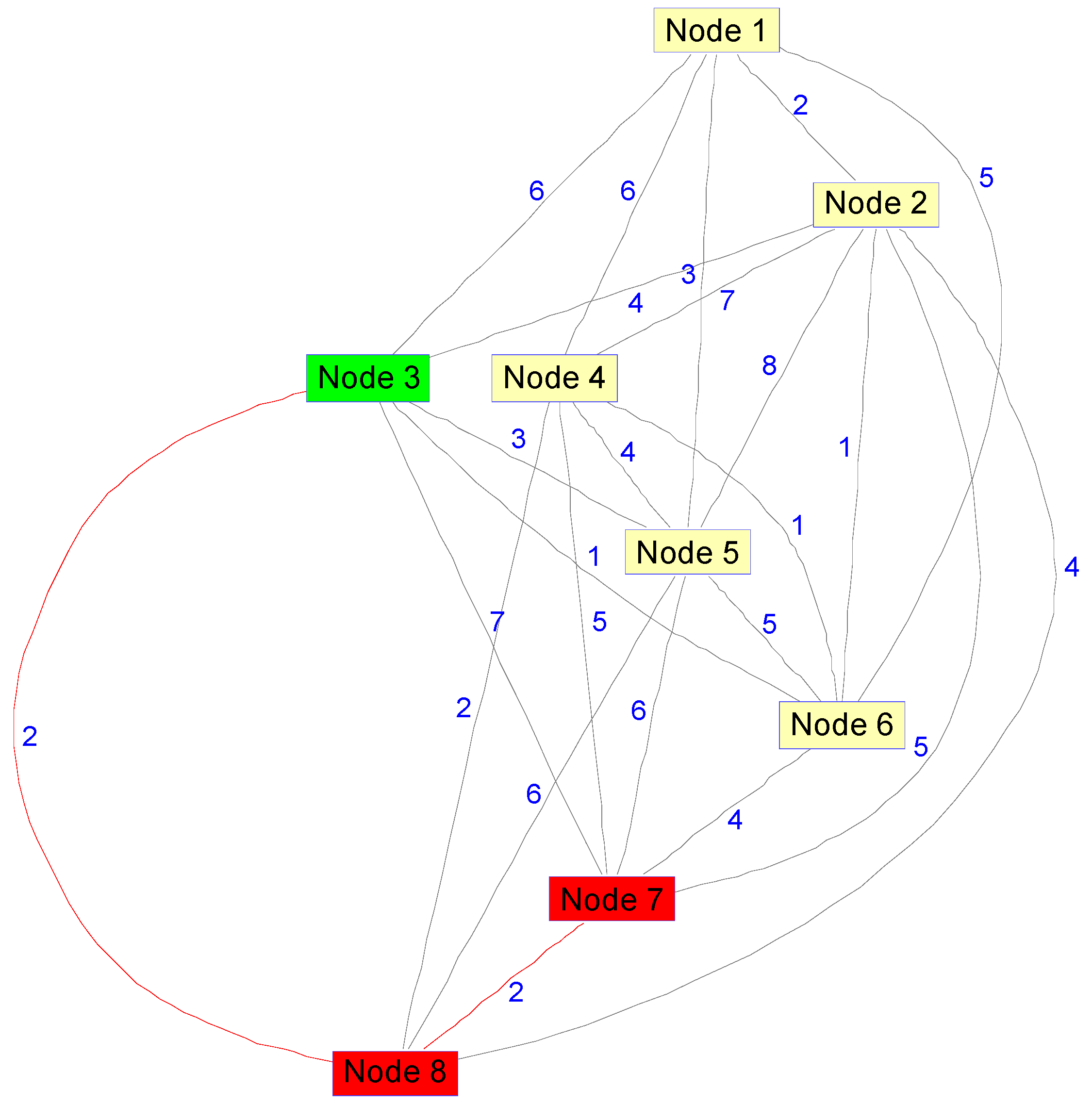
Taking Node 3 to Node 7 as an example, for Task1, the Warshall–Floyd algorithm is used to obtain the optimal path between two nodes as shown in Figure 6.
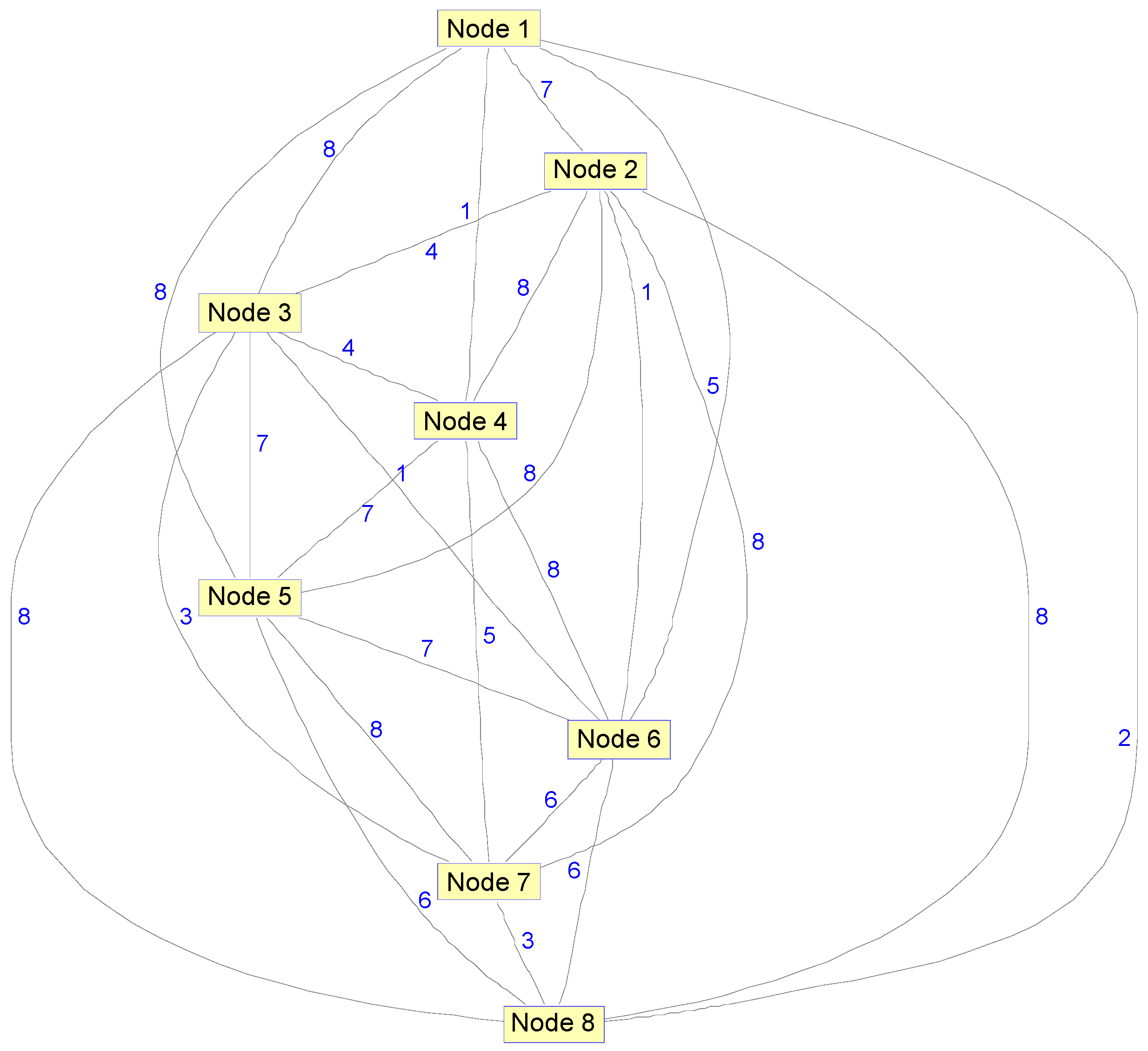
For Task2, after the parameters are reset, using the algorithm proposed in Section 4, the weight of the integrated link between any two nodes can be obtained as shown in Figure 7.
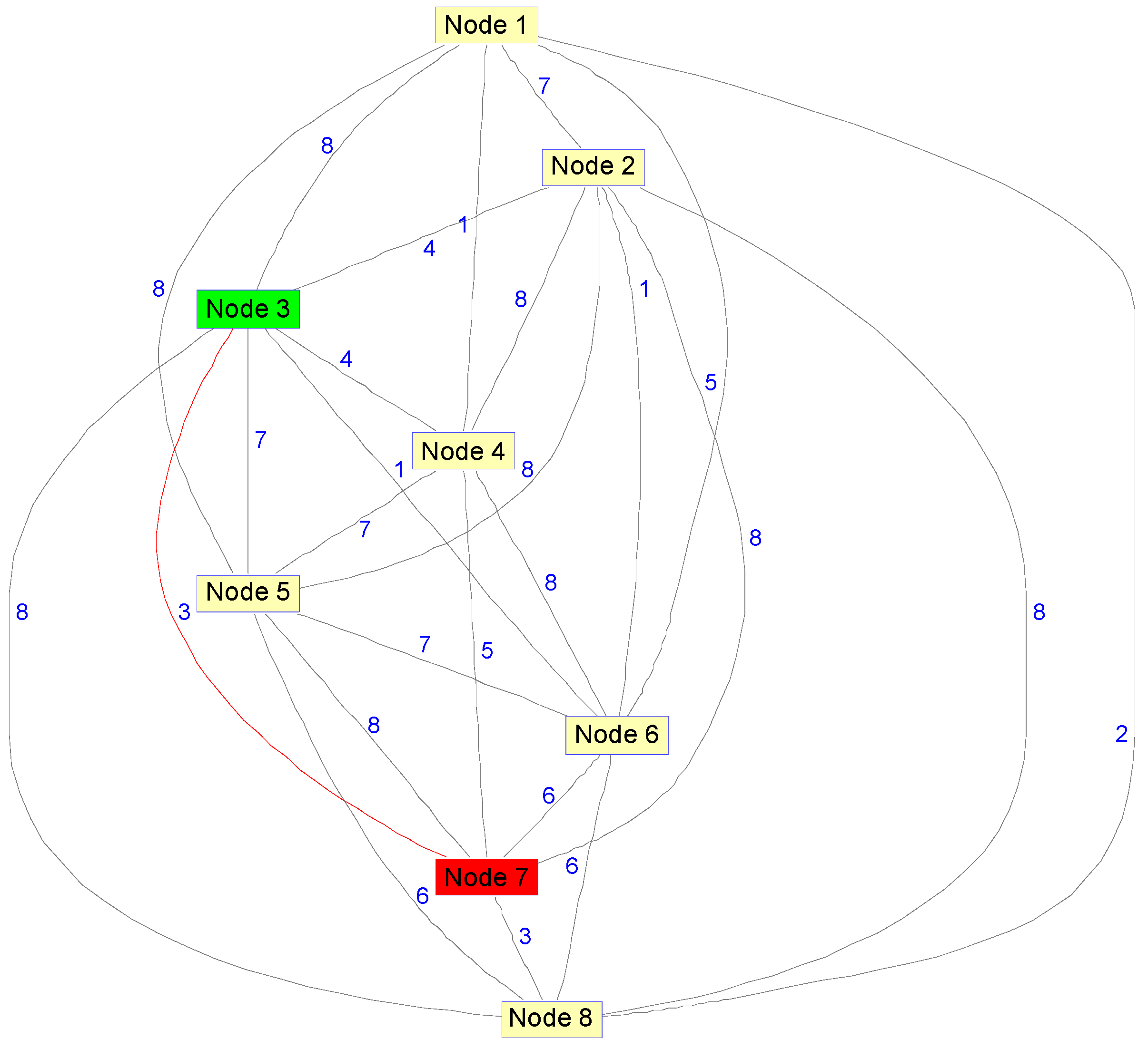
For Task2, the best path from Node 3 to Node 7 can be obtained by Warshall–Floyd algorithm as shown in Figure 8.
According to the simulation, the integrated link weights of the same link are different for different spatial tasks, and different tasks choose the path with the smallest integrated link weights to transmit, forming a multi-topology routing transmission, which can effectively improve the resource utilization efficiency of the SIN and meet the multi-task requirements of the SIN.
5.2. TBA Algorithm Simulation
In the experiment, the hardware environment is: Intel Core i7-8750CPU, 8 G memory, 1 TB hard disk space. The software environment includesSTK9.0 and MATLAB R2014a. Walker constellation is implemented in STK. The constellation parameters of Walker constellation are shown in the Table 2.
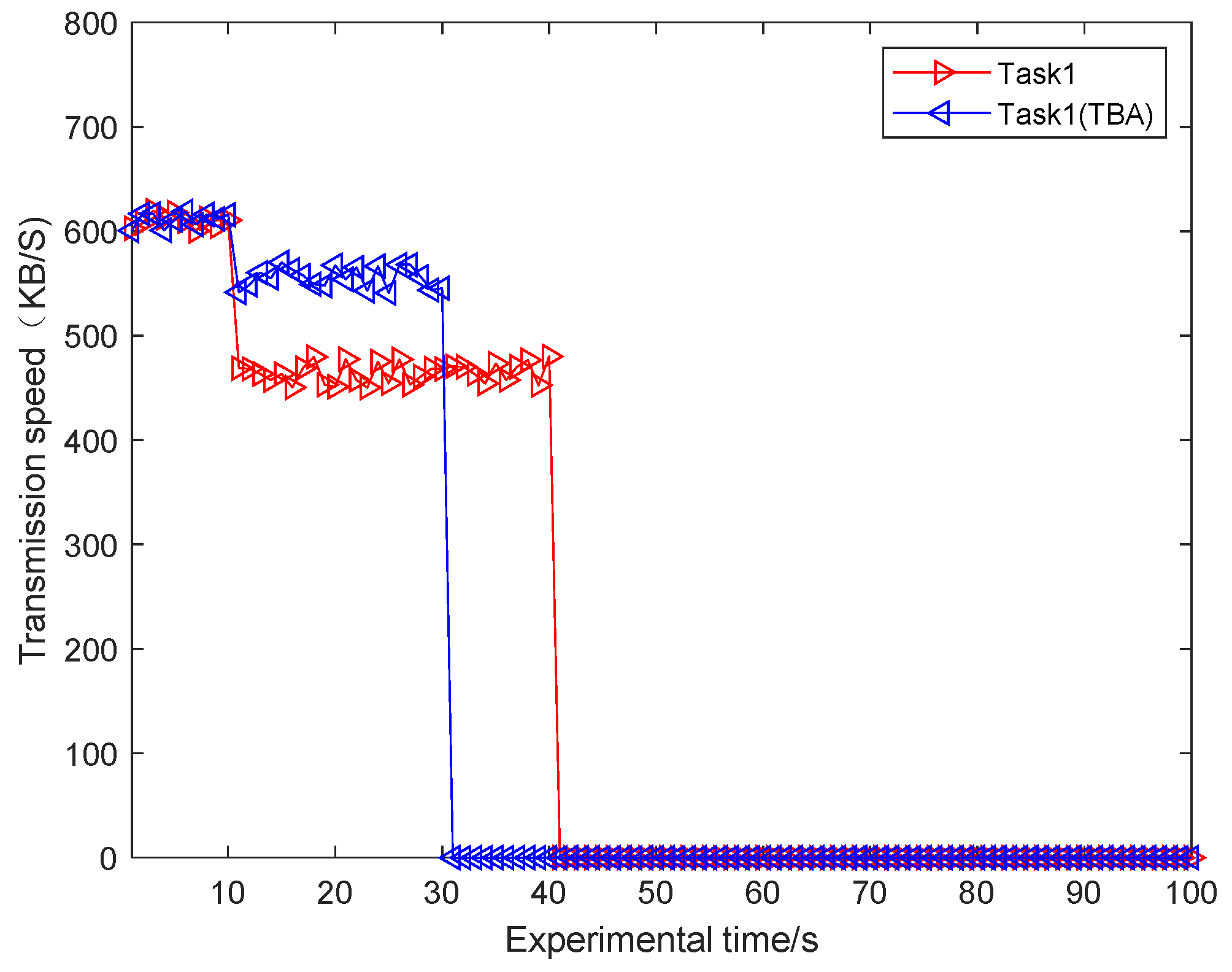
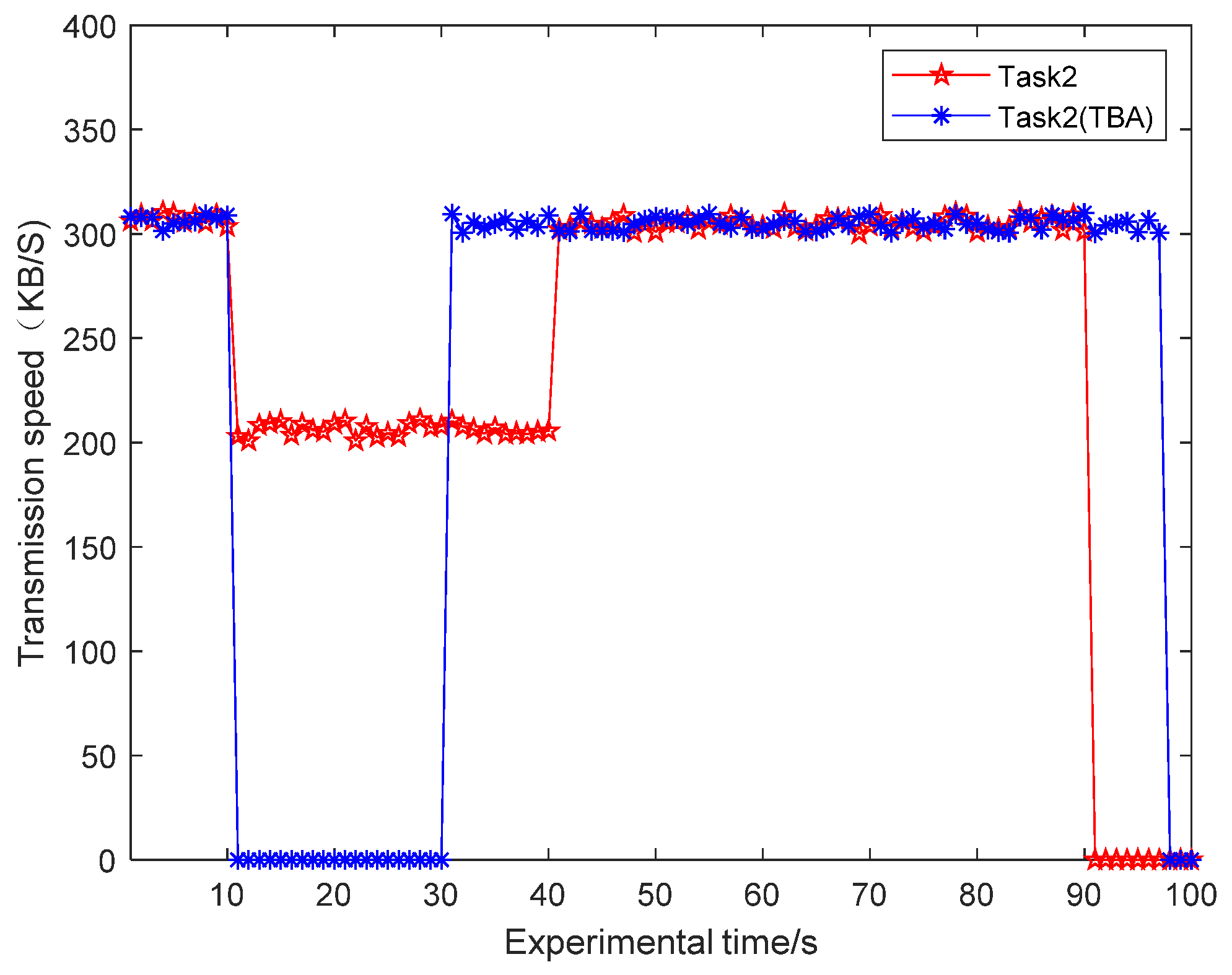
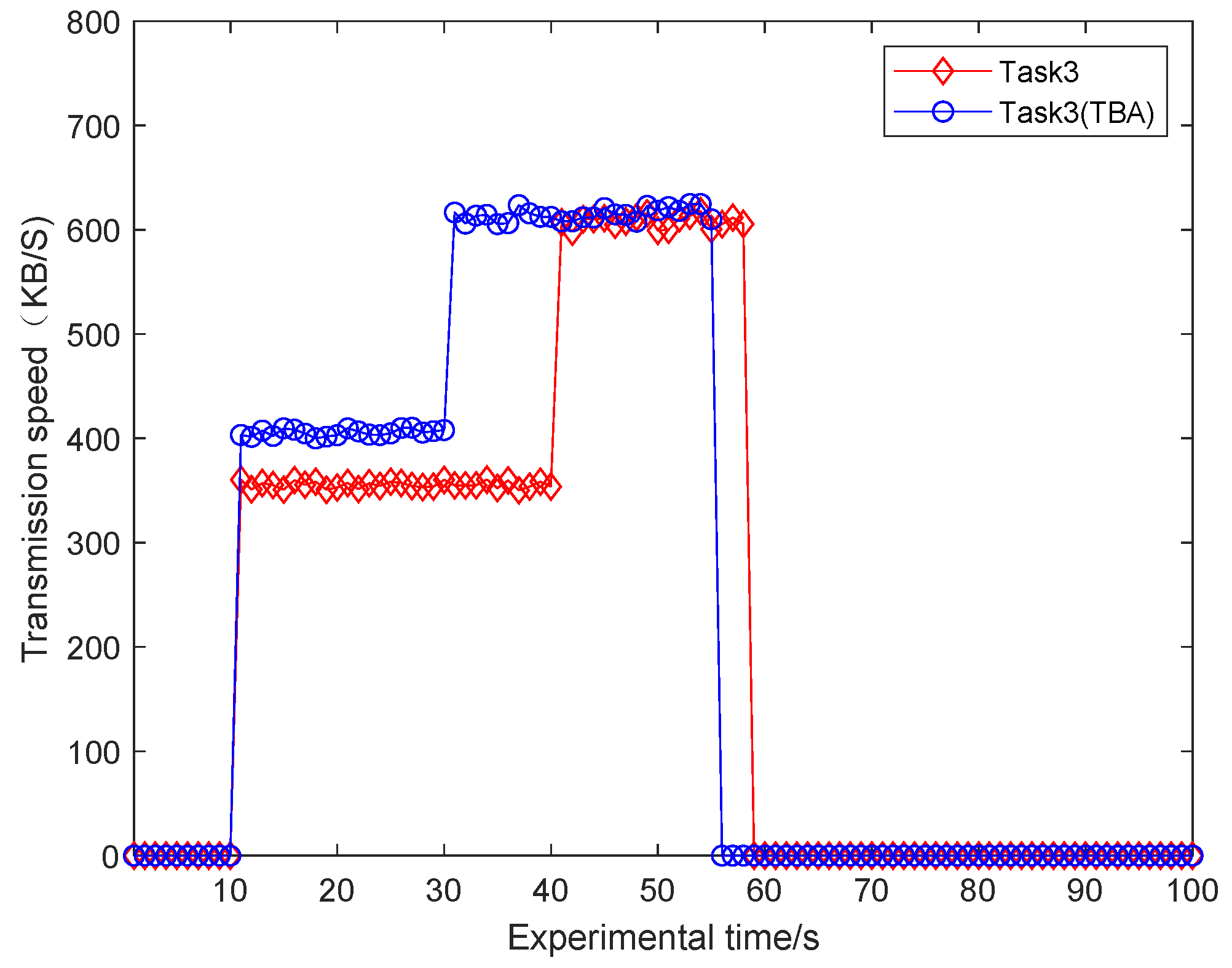
To verify the TBA algorithm, we only select two LEO satellites in the Walker constellation, the total bandwidth of the link is 1000 KBps. Packet loss rate is randomly selected between 0.5% and 1%. First, the data of Task1 and Task2 are transmitted at 600 KBps and 300 KBps respectively. Ten seconds later, Task3 data is sent at a rate of 600 KBps, with the sending rate of the three tasks as its request bandwidth. The minimum required bandwidth of Task1, Task2, and Task3 are 400 KBps, 100 KBps and 300 KBps respectively. The bandwidth allocation factors of Task1, Task2 and Task3 are 0.9, 0.1 and 0.67, respectively. Here, we define a new variable, Bandwidth Satisfaction Ratio (BSR), to allocate the ratio of the actual bandwidth to the requested bandwidth . The BSR expression for the r-hop in the physical link is as follows.
For Task1, Task2, and Task3, the simulation results without TBA algorithm and using TBA algorithm are shown Figure 9, Figure 10 and Figure 11 respectively.
The experimental results show that for Task1, it can transmit at full speed at the beginning of transmission. After 10 s, the data transmission rate of Task1 decreases to about 450 KBps without TBA algorithm because of the start of Task3 data transmission, when using TBA algorithm, the data transmission rate of Task1 decreases to about 573 KBps. For Task2, it can transmit at full speed at the beginning of transmission. After 10 s, the data transmission rate of Task2 decreases to about 200 KBps without TBA algorithm because of the start of Task3 data transmission, when using TBA algorithm, Task2 can only share the bandwidth of 60 KBps, so it cannot effectively transmit information and terminate its transmission. For Task3, the transmission rate is 350 KBps without TBA algorithm, and 427 KBps with TBA algorithm.
The simulation results show that the bandwidth satisfactions of Task1, Task2 and Task3 are 75%, 66.7% and 58.3% respectively without TBA algorithm. With the proposed TBA algorithm, Task1 and Task3 are more important and have higher bandwidth allocation factor. Their bandwidth satisfactions are 95.5% and 71.2%, which are increased by 20.5% and 12.9% respectively. Therefore, the TBA algorithm proposed in this paper is conducive to ensuring the timely transmission of important task data for special users, and can terminate the transmission of users who do not meet the transmission conditions, thus avoiding the waste of resources.
6. Discussion and Conclusions
Aiming at the complex structure of the SIN and the dynamic change of network topology, this paper firstly established a SIN management framework based on SDN. By establishing three kinds of network controllers and resource management and dispatching centers of the SIN on the ground, the burden of satellite nodes is reduced, which is beneficial to the unified management of global resources. On this basis, the implementation steps of the SIN routing algorithm based on a snapshot sequence are designed. Aiming at the different QoS requirements of different spatial tasks in the SIN, taking full account of dedicated bandwidth, end-to-end delay, delay jitter, packet loss rate, node busyness and delay forwarding time, the calculation methods of the initial link weight and integrated link weight are studied. Then the Warshall–Floyd algorithm is used to design the optimal routing strategy for different spatial tasks. Finally, a TBA allocation algorithm is proposed for different spatial tasks running on the same link at the same time, which effectively guarantees the timely transmission of important task data. The research content of this paper provided a scheme for efficient and reliable transmission of the SIN. The research in this paper is based on the condition that the resource requirement of space task is unchanged, and lacks the consideration of the dynamic characteristics of the SIN. In the follow-up study, the dynamic routing algorithm of the SIN will be analyzed.
Author Contributions
X.M., L.W., and S.Y. completed the overviews and methods; X.M. structured the evolution model; X.M. accomplished the theory and simulation verification; X.M. wrote the paper.
Funding
This work was primarily supported by China Equipment Named Research Funded Project with grant number 6142010010301.
Conflicts of Interest
The authors declare no conflicts of interest.
References
- Yu, Q.Y.; Meng, W.X.; Yang, M.C.; Zheng, L.M.; Zhang, Z.Z. Virtual multi-beamforming for distributed satellite clusters in space information networks. IEEE Wirel. Commun. 2016, 23, 95–101. [Google Scholar] [CrossRef]
- Zhang, W. Topological Control Theory and Method of Space Information Network; PLA University of Science and Technology: Nanjing, China, 2016; pp. 1–5. [Google Scholar]
- Tang, Q. Research on Routing Strategy Based on QoS in Aerospace Environment; Harbin Institute of Technology: Harbin, China, 2016; pp. 30–50. [Google Scholar]
- Yang, S.Q. Research on Software-Defined Satellite Network Architecture; University of Electronic Science and Technology of China: Chengdu, China, 2016; pp. 20–24. [Google Scholar]
- Ekici, E.; Akyildiz, I.F.; Bender, M.D. A distributed routing algorithm for datagram traffic in LEO satelitte networks. IEEE/ACM Transac. Netw. 2001, 9, 137–147. [Google Scholar] [CrossRef]
- Gounder, V.V.; Prakash, R.; Abu-Amara, H. Routing in LEO-based satellite networks. In Proceedings of the 1999 IEEE Emerging Technologies Symposium on Wireless Communications and Systems, Richardson, TX, USA, 12–13 April 1999; pp. 221–226. [Google Scholar]
- Min, S.L.; Kim, D.N.; Kim, C.S.; Chang, H.S.; Kim, B.W.; Lee, C.G.; Min, S.L.; Choi, Y.; Yang, H.S. FSA-Based Link assignment and routing in Low-Earth orbit satellite networks. IEEE Transac. Veh. Technol. 1998, 8, 1037–1048. [Google Scholar]
- Lu, Y.; Zhao, Y.; Sun, F.; Li, H.; Ni, G.; Wang, D.J. Routing Techniques on Satellite Networks. J. Softw. 2014, 25, 1085–1100. [Google Scholar]
- Li, H.P. Joint Route Selection and Resource Allocation Algorithms in Software-Defined Networking; Chongqing University of Posts and Telecommunications: Chongqing, China, 2017; pp. 11–14. [Google Scholar]
- Aini, A.; Salehipour, A. Speeding up the Floyd–Warshall algorithm for the cycled shortest path problem. Appl. Math. Lett. 2012, 25, 1–5. [Google Scholar] [CrossRef] [Green Version]
- Zhu, S.Y. Research on Routing Algorithm of Space Network Based on SDN; Harbin Institute of Technology: Harbin, China, 2017; pp. 1–19. [Google Scholar]
- Nguyen, V.G.; Do, T.X.; Kim, Y.H. SDN and Virtualization-Based LTE Mobile Network Architectures: A Comprehensive Survey. Wirel. Pers. Commun. 2016, 86, 1401–1438. [Google Scholar] [CrossRef]
- Akhunzada, A.; Khan, M.K. Toward Secure Software Defined Vehicular Networks: Taxonomy, Requirements, and Open Issues. IEEE Commun. Mag. 2017, 55, 110–118. [Google Scholar] [CrossRef]
- Bao, J.; Zhao, B.; Yu, W.; Feng, Z.; Wu, C.; Gong, Z. OpenSAN: A software-defined satellite network architecture. ACM SIGCOMM Comput. Commun. Rev. 2014, 44, 347–348. [Google Scholar] [CrossRef]
- Li, T.; Zhou, H.; Luo, H.; Xu, Q.; Ye, Y. Using SDN and NFV to Implement Satellite Communication Networks. In Proceedings of the 2016 International Conference on Networking and Network Applications (NaNA), Hokkaido, Japan, 23–25 July 2016; pp. 131–134. [Google Scholar]
- Ren, R.W. Research on the SDN-Based Controller of Space-Sky Information Network; Beijing University of Posts and Telecommunications: Beijing, China, 2015; pp. 23–33. [Google Scholar]
- Jing, Y.G. Design of Distributed Controller and Reliability Research on Software Defined Space-Sky Information Network; Beijing University of Posts and Telecommunications: Beijing, China, 2017; pp. 15–32. [Google Scholar]
- Gardikis, G.; Koumaras, H.; Sakkas, C. Towards SDN/NFV-enabled satellite networks. Telecommun. Syst. 2017, 66, 1–14. [Google Scholar] [CrossRef]
- Bertaux, L.; Medjiah, S.; Berthou, P.; Abdellatif, S.; Hakiri, A.; Gelard, P.; Planchou, F.; Bruyere, M. Software defined networking and virtualization for broadband satellite networks. IEEE Commun. Mag. 2015, 53, 54–60. [Google Scholar] [CrossRef] [Green Version]
- Yu, Q.; Wang, J.C.; Bai, L. Architecture and critical technologies of space information networks. J. Commun. Inf. Netw. 2016, 1, 1–9. [Google Scholar] [CrossRef] [Green Version]
- Tian, R. Research on Control Protocol and Routing Algorithms of Software Defined Space-Terrestrial Network; Beijing University of Posts and Telecommunications: Beijing, China, 2017; pp. 9–16. [Google Scholar]
- Nguyen, X.-N.; Saucez, D.; Barakat, C.; Turletti, T. Rules Placement Problem in OpenFlow Networks: A Survey. IEEE Commun. Surv. Tutor. 2016, 18, 1273–1286. [Google Scholar] [CrossRef]
- Huang, J.; Su, Y.; Huang, L.; Liu, W.; Wang, F. An Optimized Snapshot Division Strategy for Satellite Network in GNSS. IEEE Commun. Lett. 2016, 20, 1. [Google Scholar] [CrossRef]
- Yan, D.; Guo, J.; Wang, L.; Zhan, P. SADR: Network status adaptive QoS dynamic routing for satellite networks. In Proceedings of the 2016 IEEE 13th International Conference on Signal Processing (ICSP), Chengdu, China, 6–10 November 2016; pp. 1186–1190. [Google Scholar]
- Qi, X.H. Research on Key Networking Technologies Based on Multiple Satellites Collaboration in Space Information Network; Beijing University of Posts and Telecommunications: Beijing, China, 2015; pp. 35–40. [Google Scholar]
- Li, T.; Zhou, H.; Luo, H.; Yu, S. A Software Defined Framework for Integrated Space-Terrestrial Satellite Communication. IEEE Trans. Mob. Comput. 2018, 17, 703–716. [Google Scholar] [CrossRef]
- Li, T.X. Research on Modeling and Resource Adaptation Methods in Smart Collaborative Network Based Space Networks; Beijing Jiaotong University: Beijing, China, 2018; pp. 83–99. [Google Scholar]
- Muholzoev, A.V.; Masyagin, V.B. Probabilistic Calculation of Tolerances of the Dimension Chain Based on the Floyd-warshall Algorithm. Proc. Eng. 2016, 150, 959–962. [Google Scholar] [CrossRef] [Green Version]
Figure 1.
Software-defined Networking (SDN) structure.

Figure 2.
Space information networks (SIN) management framework based on SDN.

Figure 3.
Routing algorithm flow based on snapshot sequence.

Figure 4.
Schematic diagram of delay forwarding routing.

Figure 5.
Schematic diagram of integrated link weight of Task1.

Figure 6.
Task1 best route diagram.

Figure 7.
Schematic diagram of integrated link weight of Task2.

Figure 8.
Task2 best route diagram.

Figure 9.
Task1 transmission rate comparison schematic diagram.

Figure 10.
Task2 transmission rate comparison schematic diagram.

Figure 11.
Task3 transmission rate comparison schematic diagram.


Table 1.
Delay Forwarding Routing Query Schedule.
| Busy Degree | Delay Forwarding Routing Query Time (s) |
|---|---|
| [0, 0.3) | 0 |
| [0.3, 0.5) | 0.3 |
| [0.5, 0.8) | 0.6 |
| [0.8, 1) | 1 |
Table 2.
Walker constellation parameter.
| Number of Satellites | Orbital Altitude/km | Orbital Inclination | Orbital Period/s | Orbit Number | Link State | Minimum Elevation | |
|---|---|---|---|---|---|---|---|
| MEO | 12 | 10,355 | 55.0 | 21,600 | 3 | Permanent | 22 |
| LEO | 48 | 1400 | 52.0 | 6840 | 8 | Permanent | 10 |
© 2019 by the authors. Licensee MDPI, Basel, Switzerland. This article is an open access article distributed under the terms and conditions of the Creative Commons Attribution (CC BY) license (http://creativecommons.org/licenses/by/4.0/).
Share and Cite
MDPI and ACS Style
Meng, X.; Wu, L.; Yu, S. Multi-Topology Routing Algorithms in SDN-Based Space Information Networks. Future Internet 2019, 11, 15. https://doi.org/10.3390/fi11010015
AMA Style
Meng X, Wu L, Yu S. Multi-Topology Routing Algorithms in SDN-Based Space Information Networks. Future Internet. 2019; 11(1):15. https://doi.org/10.3390/fi11010015
Chicago/Turabian StyleMeng, Xiangli, Lingda Wu, and Shaobo Yu. 2019. "Multi-Topology Routing Algorithms in SDN-Based Space Information Networks" Future Internet 11, no. 1: 15. https://doi.org/10.3390/fi11010015
Note that from the first issue of 2016, this journal uses article numbers instead of page numbers. See further details here.