Development of a Social DTN for Message Communication between SNS Group Members


1
Department of Information Systems Science, Faculty of Engineering, Soka University, 1-236 Tangi-cho, Hachioji-shi 192-8577, Japan
2
Information Systems Science Major, Graduate School of Engineering, Soka University, 1-236 Tangi-cho, Hachioji-shi 192-8577, Japan
*
Author to whom correspondence should be addressed.
Future Internet 2018, 10(4), 32; https://doi.org/10.3390/fi10040032
Submission received: 22 March 2018
/
Revised: 1 April 2018
/
Accepted: 3 April 2018
/
Published: 4 April 2018
Abstract
:Smartphones have the ability to communicate with other terminals through ad hoc connections. A variety of applications have been developed to exploit this ability. The authors have developed an Android OS (operating system) application (called “social DTN manager”) that builds a DTN (delay, disruption, disconnection tolerant networking) among members of a social networking service (SNS) community using a community token. The members can exchange messages over this network. Control messages for building a DTN are forwarded to only those nodes that use the same community token in order to reduce flooding of message copies. When a source node sends a communication request to its destination node, they exchange control messages to establish a communication route. Relay nodes use these messages to create and hold routing information for these nodes in their routing tables. Thereafter, relay nodes can forward data messages based on their routing tables. This again reduces flooding of message copies. The social DTN manager incorporates these functions, Facebook Graph API and Google Nearby Connections API. The authors have installed it in Android terminals and confirmed that a social DTN can successfully be built using this application and that data messages can be exchanged between terminals via reactive routes.
1. Introduction
Today, people at almost any place can access the Internet using mobile terminals by subscribing to a mobile communication carrier. They can also access the Internet via public wireless local area networks (LANs) that are provided at public places. Thus, pervasive social networking (PSN) [1] environments, in which people can access social network services (SNS) anytime from anywhere, are gradually expanding. However, public wireless LANs are not yet widely available in Japan and thus visitors from abroad can exchange messages via the Internet only in limited places.
Smartphones, which are highly sophisticated, have the ability to set up an ad hoc connection. A variety of applications are being studied to exploit this ability. The authors proposed to use a social MANET (mobile ad hoc network) [2], which is constructed by identifying terminals that belong to a certain SNS community, to expand the area where Internet access is possible beyond public wireless LAN areas.
DTN (delay, disruption, disconnection tolerant networking) [3,4,5,6,7,8,9,10,11] has been studied to achieve reliable data transfer even in an inferior communication environment in which network interruptions or long delays occur frequently. However, if a malicious node participates in a DTN, it can disturb the network operation. Therefore, it is necessary to study how to limit nodes that participate in a DTN.
We have developed an Android OS (operating system) application that enables members of an SNS community to build a DTN and exchange messages through it. A community token is used to identify members of the same group. We proposed methods of creating and sharing a community token to identify community members in [2]. Use of this token can limit terminals that participate in a DTN and thus ensure network security. To reduce flooding of message copies for constructing a DTN, control messages are forwarded to only those nodes that hold the same community token. In addition, when a source node sends a communication request to its destination node, these nodes exchange control messages to establish a communication route. Relay nodes use these messages to create and hold routing information for these nodes in their routing tables. Thereafter, relay nodes can forward data messages based on their routing tables. This again reduces flooding of message copies. We have developed a social DTN manager that incorporates these functions, Facebook Graph API [12] and Google Nearby Connections API [13], and installed it in Android terminals and confirmed that a social DTN can successfully be built. Section 2 presents related studies and the position of the method proposed in this paper. Section 3 describes how a social DTN can be built. Section 4 explains the experimental social DTN manager we have built. Section 5 verifies that the experimental social DTN manager operates as expected and evaluates route establishment time in a DTN that was built with Android terminals in which the experimental social DTN manager was installed. Section 6 presents conclusions and future issues.
2. Related Studies
This section presents related studies of DTN routing, the creation of a routing table and how to build an ad hoc network among Android terminals. It also describes the position of the proposed method.
2.1. DTN Routing
Well-known DTN routing methods include epidemic routing [4], Spray and Wait [5], location-based routing [6], and the motion vector scheme (MoVe) [6]. Epidemic routing attempts to send a message to the destination node by propagating copies of a bundle to surrounding nodes unconditionally and without restrictions. In contrast, Spray and Wait suppresses resource depletion by setting an upper limit to the number of copies that can be created. Location-based routing assumes that all nodes involved in message relaying are informed of the location of the destination node. It makes each of these nodes forward a message to an adjacent node that is located closer to the destination node than itself until the message reaches the destination. Although this routing principle of selecting the next relay node based on location information is the simplest, there is no guarantee that the bundle-relaying node moves close to the destination node. MoVe uses motion vectors (i.e., moving speed vectors) instead of location information in order to raise the probability at which the relaying node moves towards the destination node. In these methods, no node holds a routing table, a table which contains information about the relaying nodes that forward messages between the source node and destination node.
Existing routing methods that use dedicated relay nodes include message ferry [7] and routing based on traveling route information [8]. In the former, “ferry nodes”, which are dedicated relay nodes, travel through clusters, are places where some or all nodes are likely to come together. Ferry nodes have routing tables for all nodes or all clusters. In routing based on traveling route information, dedicated relay nodes have routing tables, but no routing tables for routing inside a local area because epidemic routing is applied there.
Other routing methods intended to reduce flooding of message copies include a method that creates routing tables from encounter history [9], a method that calculates the probability at which messages reach their destination nodes based on encounter probability and uses routing tables that hold this information [10], and a method that creates routing tables based on the profiles and behavior history of individuals (called “social-context-awareness” [11] in this paper).
However, these methods do not use node identification information to select nodes that participate in a DTN and thus permit all nodes to participate. In the method proposed in this paper, only those nodes that hold a community token are permitted to participate in a DTN and these nodes have routing tables.
2.2. Creation of a Routing Table
DTN routing tables can be created either proactively or reactively. In a proactive method, a routing table containing information about all nodes or dedicated relay nodes is created before communication is actually made between nodes. There are two types of proactive method: fixed type and encounter information sharing type. In the former, routing tables are created based on planned node contact patterns. In the latter, routing tables that contain information about all those nodes that have encountered each other accidentally or about all dedicated nodes are created. The sharing type is further divided into periodic sharing and passing-by sharing. In the former, nodes periodically exchange route information messages to share route information. In the latter, nodes share route information only when they pass by each other. On the other hand, in a reactive method, the source node sends a route establishment request message to the destination node when it wants to communicate with the latter. When a response message is sent back to the source node, relay nodes involved create routing tables for this connection.
Message ferry [7] and routing based on traveling route information [8] are proactive methods and are both the fixed type. There is a method in which information about a node located two hops away from the encountered node is exchanged as meta information [9,10]. Passing-by methods include PRoPHET [11] and HiBOp [14].
The proposed method is a reactive type because a route is established only when the source node wants to communicate with the destination node. Some routing tables have information about only those relay nodes that are within a limited number of hops to the destination node or that have an encounter probability within a certain range. No such restrictions are applied to the proposed method.
2.3. How to Build an Ad Hoc Network among Android Terminals
In existing methods, an ad hoc network is established among Android terminals as follows. Normal Android OS does not permit the use of ad hoc mode. Either of the following two methods is used to get around this problem. One method is to apply a patch for permitting the use of ad hoc mode to a custom Android OS, build a kernel and implement routing software that supports multiple hops [15,16]. The other method is to implement a virtual environment called Debian on an Android OS and additionally implement routing software that supports multiple hops [17]. However, these methods cannot be used with the user privilege. It is necessary to acquire the administrator privilege. Moreover, it is necessary to modify the OS of all terminals that participate in an ad hoc network.
2.4. Position of the Proposed Method
Table 1 classifies DTN routing methods according to the criteria used to determine flooding of message copies as described in Section 2.1 and according to routing table creation methods as described in Section 2.2. The proposed method identifies community members, uses routing tables to determine whether to flood message copies, and creates routing tables reactively. There are three different routing table creation methods: table format type, encounter probability calculation type and social-context-awareness type.
Table 2 compares the proposed method with existing routing methods of establishing an ad hoc network with Android terminals, as described in Section 2.3. The proposed method builds ad hoc connections between Android terminals using Nearby Connections API [13], which is independent of OS. Both Bluetooth and Wi-Fi Direct can be used.
3. How to Build a Social DTN
This section presents an overview of a service that uses a social DTN, and the functional configuration of the system that we have developed as an application for Android terminals. It also describes the procedures for creating and sharing a community token, which is a distinctive feature of this system, and a reactive route establishment method.
3.1. Service Overview
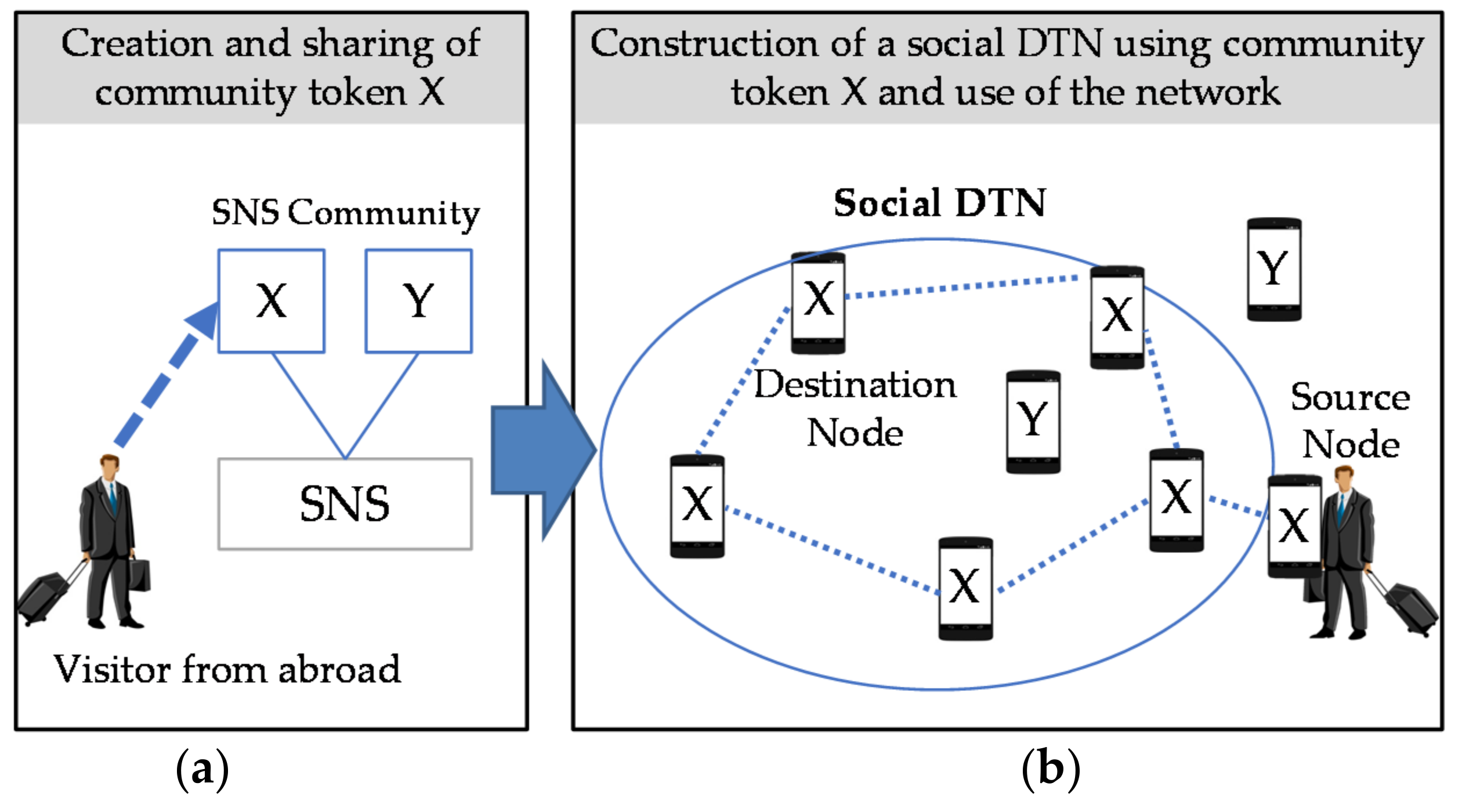
Members of an SNS community can exchange messages over an ad hoc network, a social DTN built with the terminals of these members, without using the SNS. An example of using this network is shown in Figure 1.
The authors proposed a method in which people (who are assumed to be visitors from abroad) use a community token by interacting with an SNS in [2]. The user creates a community token and uploads it to an SNS. Relay nodes that periodically search for community tokens download uploaded community tokens via the SNS and hold them. After that, users can use a community token to identify terminals that belong to the same SNS community. They can participate in an ad hoc network in the background and use DTN communication.
In the proposed social DTN and message communication, ad hoc communication between terminals and mobile carrier communication do not always need to operate simultaneously. The current research assumes that the users are visitors from abroad and that they access only public wireless LANs. As shown in the left image in Figure 1, a user in an airport or a hotel can access the Internet and browse SNSs or post messages there. As shown in the right image in Figure 1, a user touring on the street cannot make message communication with other members of the group unless there happens to a public wireless LAN. The proposed social DTN is useful in such a case. People, such as students, who subscribe to a mobile carrier but want to reduce the amount of data communication to decrease communication costs can also be candidate users of the social DTN. Even when users who have none of the above-mentioned requirements become relay nodes, there are no restrictions on simultaneous use of ad hoc communication and mobile carrier communication.
3.2. DTN Architecture
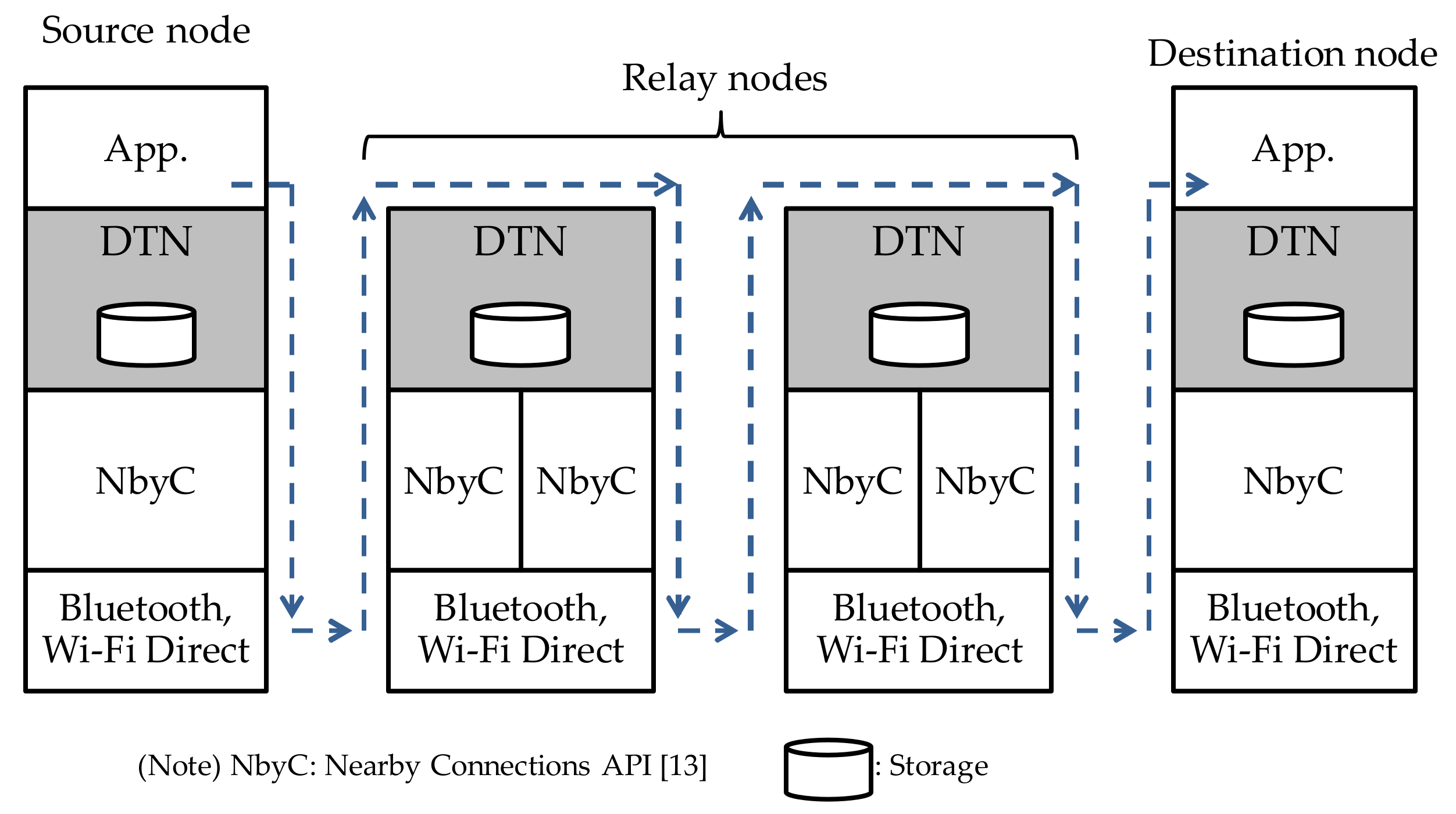
The proposed DTN architecture is shown in Figure 2. The ad hoc communication function uses Nearby Connections API [13] as well as Bluetooth and Wi-Fi Direct to establish a communication link between terminals that share the same community token. After that, a route is established and data communication is started based on the DTN routing protocol.
Nearby Connections API [13] provides several strategies. We have selected “P2P_STAR,” which is a one-to-many P2P strategy and offers high communication speed. We have used a mode in which there are N Discoverers (children) for each Advertiser (parent). The Advertiser broadcasts a communication request message, specifying two parameters: Strategy and Service ID. Service ID is an application-unique value used to identify communication made by the same application at Nearby Connections API [13]. It is set by the application developer. The Discoverer receives a broadcast message that has the same Strategy and Service ID parameters as those specified by the Advertiser. It also sends a communication request message. Both the Advertiser and the Discoverer check the communication request and Service ID sent from the other terminal, and if they both give permission, a communication link is established between the two terminals. The communication phase moves to the phase in which data, such as text and file, can be exchanged. After that, data exchange can continue until one of the two terminals disconnects the communication.
3.3. How to Create and Share a Community Token
3.3.1. How to Create a Community Token
Use of a community token was already proposed in [2]. The contents of the community token used in this system are shown in Table 3. Group ID identifies an SNS group. Token ID is a character string used to determine which community token is new. Its initial value is the MAC (Media Access Control) address of the terminal that has created the community token. The value is incremented by one each time the community token is updated. Updating of a community token becomes necessary when a member newly joints or leaves an SNS group. The above-mentioned updating mechanism discriminates between old and new token IDs to prevent an old community token from being used by mistake. Max-Battery of Device (MBoD) is the maximum level of battery power consumption permitted when a terminal operates as a relay node.
3.3.2. How to Obtain Group Information and Share a Community Token
Facebook has been used as an SNS for sharing a community token. An application that incorporates Facebook Graph API [12] has been developed. Nodes obtain Facebook group information, create a community token and manage (i.e., post and delete) it. A community token is created from a user-unique access token issued by Facebook. Therefore, users obtain a Group ID publicized in each Facebook group. Specifically, a node sends a GET request to the Facebook group node via Facebook Graph API [12]. The Facebook group node sends group information back to the user as a response. The application that has received it extracts a Facebook group ID from it. The sequence of steps needed for a node to obtain group information is shown in Figure 3a.
To share the created community token with other participants, the user posts a message with a message ID added to the group. The message ID indicates that the message contains a community token. The character string “Token” is used as the message ID. When a group is created in Facebook, a Facebook group ID is assigned to it. It is a 16-digit number unique to the group. It is used to indicate which group the community token has been created for. The sequence of steps needed for a group to share information is shown in Figure 3b.
3.4. DTN Routing Protocol
A reactive routing protocol has been designed by referring to the AODV (Ad-hoc On-Demand Distance Vector) protocol [18], which is a representative MANET (mobile ad-hoc network) protocol. The aim of this design was that, since nodes that make up the DTN are mobile terminals, we wanted to reduce the consumption of their resources as much as possible. In other words, a route is established between nodes only when there is a request for message communication between these nodes. Only during communication, relay nodes need to hold resources for that communication. However, unlike MANET, mesh-network-based communication is not possible because Nearby Connections API [13] is used. Only ad hoc communication is possible. Therefore, we describe a function that stores, carries and forwards a message through repetitive connections and disconnections of an ad hoc communication link.
3.4.1. Routing Message Type and Creation of a Routing Table
Route establishment operation starts when the source node sends a route establishment request (rreQ_m) to the destination node. A relay node that has received this request creates a routing table entry with the destination node address (DA) in the message as the terminal node address (TNA), and the address of the adjacent node that forwarded this message as the relay node address (RNA). It then forwards the message. The destination node that has received the route establishment request (rreQ_m) creates a route establishment response (rreP_m) with the source node (SA) as its destination and sends it back to the adjacent node from which it has received the route establishment request. A node that has received this message completes the routing table with the source node address as the terminal node address, and the address of the adjacent node that has sent the message as the relay node address. Relay nodes repeat this routing table creation until the route is established up to the source node. After that, the source node sends data messages (dsnD_m), which contain text, image, etc., to the destination node. A relay node selects a relay node with an RNA whose TNA is identical to the DA in the received message (dsnD_m) as the relay node to which it will forward the message. This is repeated until the message reaches the destination node.
The message types and message elements described above are shown in Table 4. The route establishment request ID is a message used to indicate which route establishment request is new. Its initial value is “1”. It is incremented by one each time the source node sends a route establishment request. The MAC address of each terminal is used as the DA and SA for that terminal. The structure of a routing table is shown in Table 5.
3.4.2. Algorithm for Sending Messages
This subsection describes the algorithm used by the Advertiser when the user requests the application to send a message. The Advertiser uses the Algorithm 1 to select the node to which it will forward the message.
| Algorithm 1. Algorithm for Sending Messages |
|
3.4.3. Algorithm for Receiving Messages
This subsection describes the Algorithm 2 used by the Discoverer to selectively receive a message from the Advertiser. The acceptance analysis tree in Step 3 is shown in Figure 4.
| Algorithm 2. Algorithm for Receiving Messages |
|
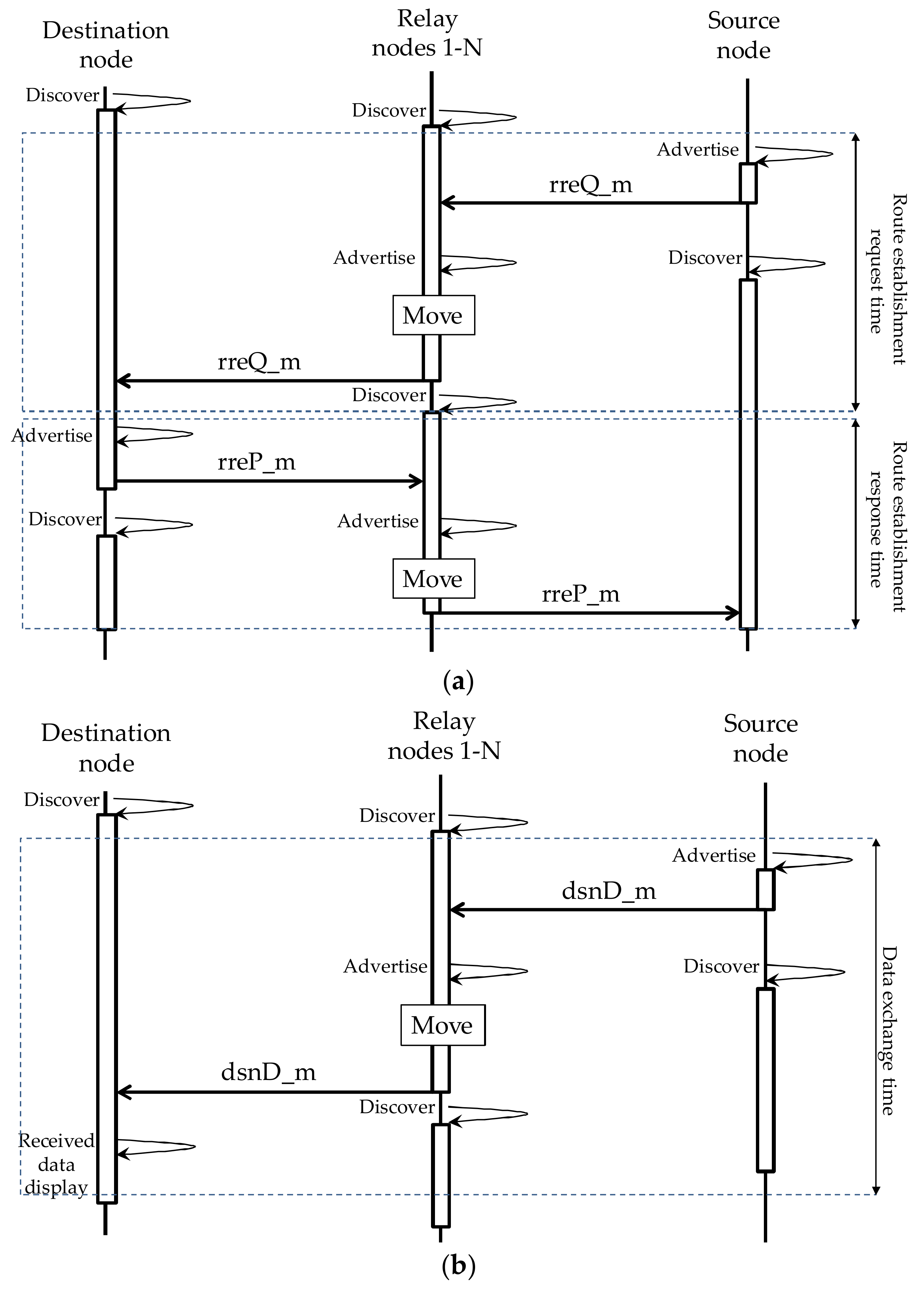
3.5. Message Sequence for Establishing a Route
The sequence of message exchanges for establishing routes and exchanging data is shown in Figure 5. Since Nearby Connections API [13] is used, the discovery phase and the advertising phase are also shown. Message transmission takes place in the advertising phase while message reception takes place in the discovery phase. “Move” means moving to one of the relay nodes 1 to N. The definitions of route establishment request time, route establishment response time, and data exchange time are also shown in Figure 5.
4. Development of an Experimental Social DTN Manager Application
We have developed an experimental system application, called “social DTN manager.” The functions implemented and the development environment used are described below. Some of the graphical user interfaces (GUIs) used in the experimental system are also shown.
4.1. Functions Implemented in the System
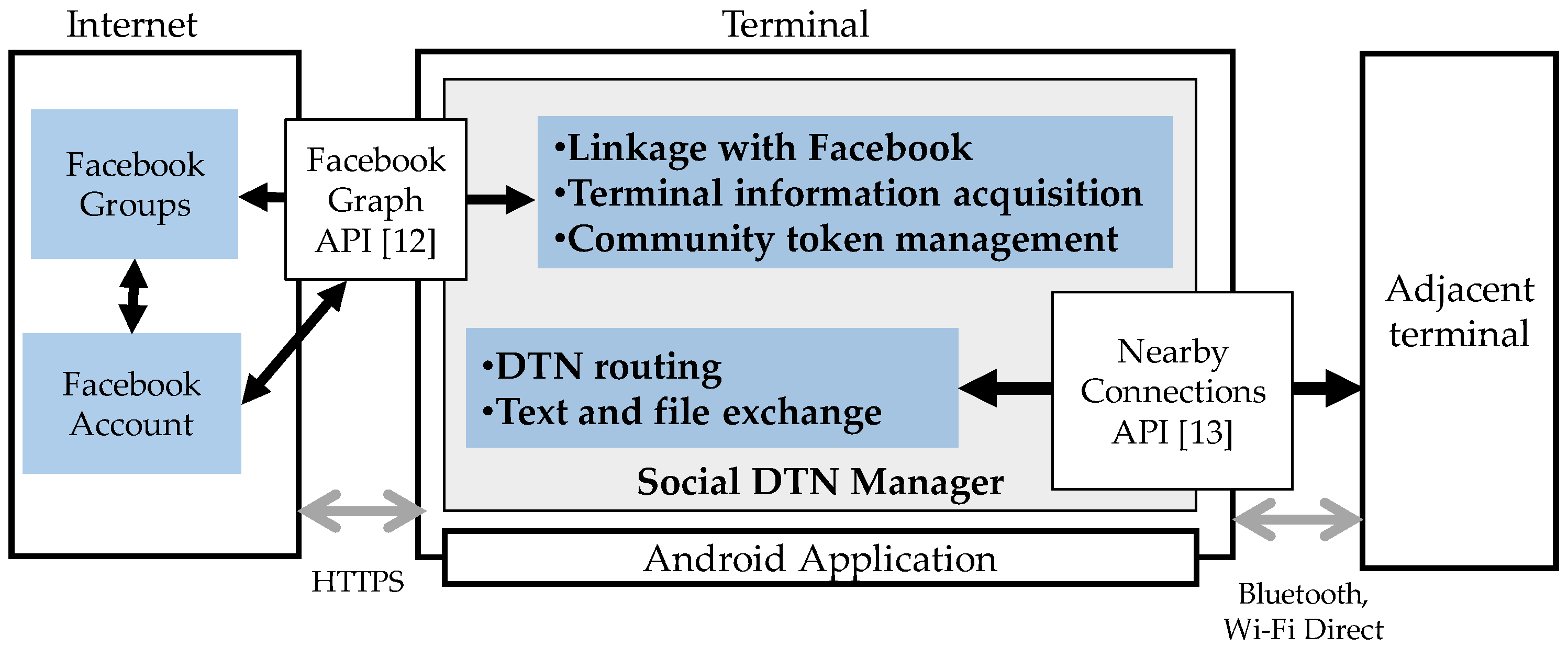
The system configuration of the application is shown in Figure 6. This Android application is mainly written in Java JDK 8. It obtains account information, information about the group the user belongs to and messages generated within the group from Facebook via Facebook Graph API [12]. It also posts or deletes messages. In addition, it makes DTN communication with the social DTN managers on other terminals via Nearby Connections API [13] using Bluetooth or Wi-Fi Direct. Service ID, which is used to authenticate an ad hoc communication link, consists of application package name, Group ID of the community token, and the source node address of the community token.
4.2. GUI of the Social DTN Manager
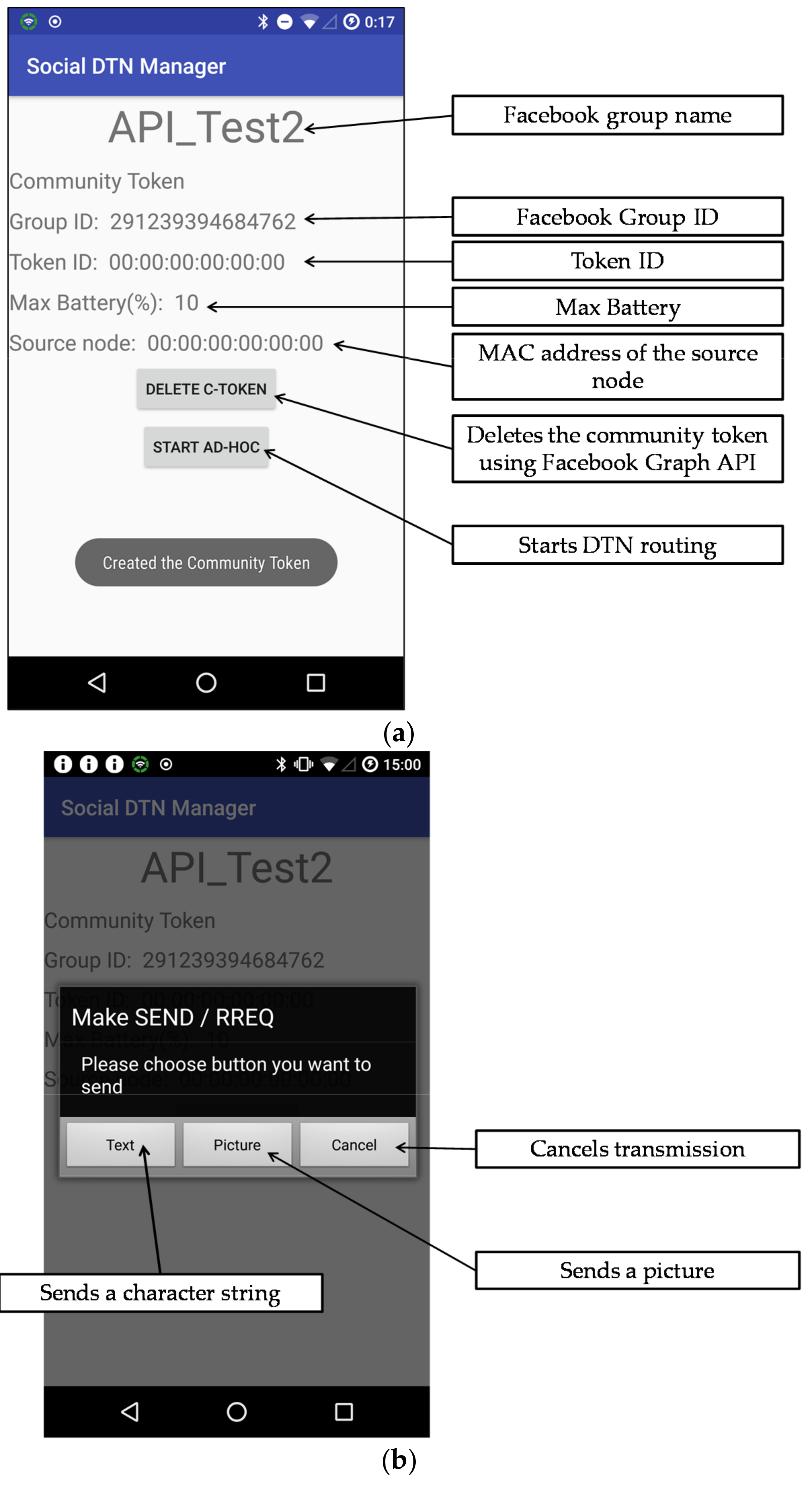
We developed two or three GUIs for each function listed in Table 6. The GUI for Linkage to Facebook and that for text and file exchange are shown in Figure 7. Figure 7a shows the GUI layout for a case where there exists a community token created by the user. The user can confirm the Facebook group name and the community token through this GUI. Icons for deleting a community token and starting a connection are provided. Figure 7b show the GUI layout used by the user to select the type of message he/she wants to create.
5. Evaluation
This section presents the results of the operation test of the experimental application, and measurements of route establishment time and data transmission time as well as measurement conditions.
5.1. Operation Test of the Social DTN Manager
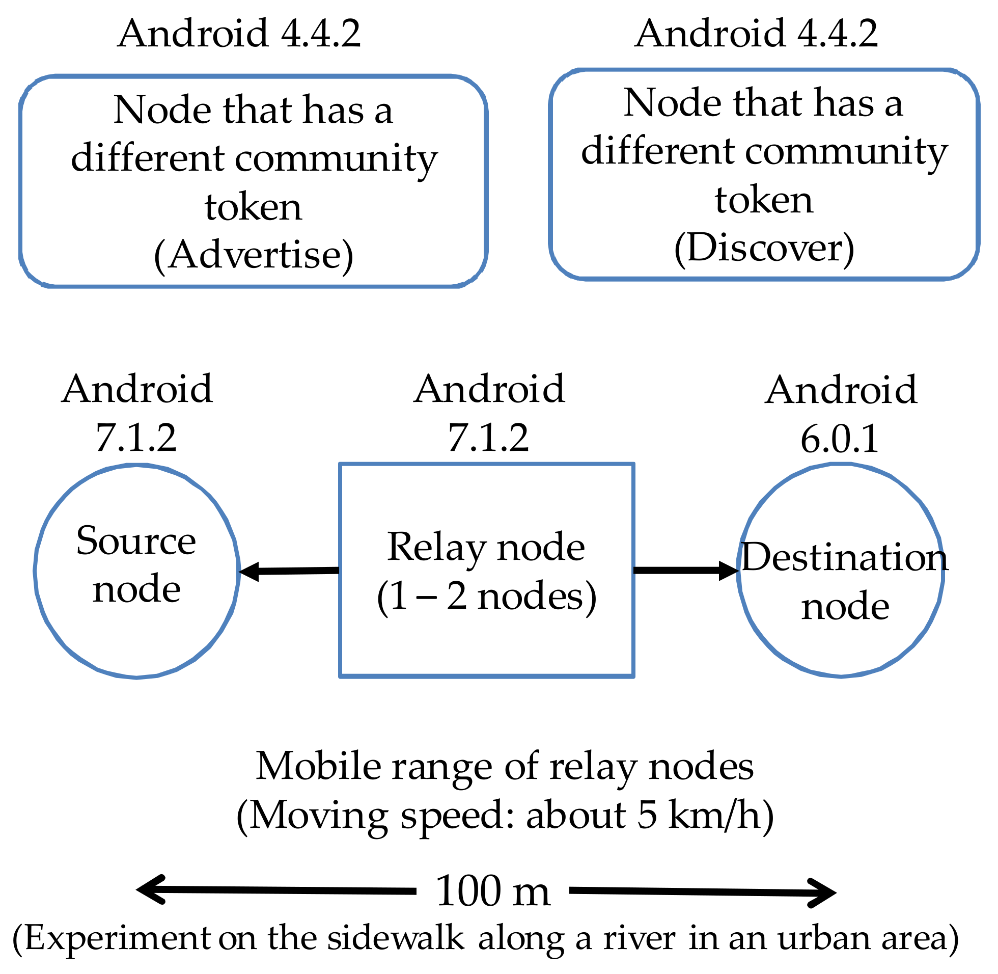
To verify the operation of the experimental application, we created and shared a community token through linkage with Facebook and established a route between the source node and the destination node. A character string or an image file registered by the source node was sent to the destination node. The specifications of the terminals used in the experiment are shown in Table 8. The structure of the experimental network is shown in Figure 8. The source node, the destination node and 1 to 4 relay nodes were laid out along a line 100 m long or 250 m long. All terminals had the same community token. The source node and the destination node were fixed, and relay nodes were carried by persons, who walked at a speed of about 5 km/h. A 55-kilobyte-character string was created at the source node and sent to the destination node. A 1-Mbyte image file was also sent.
An example of sending text from the source node for the first time is described below along with terminal display images.
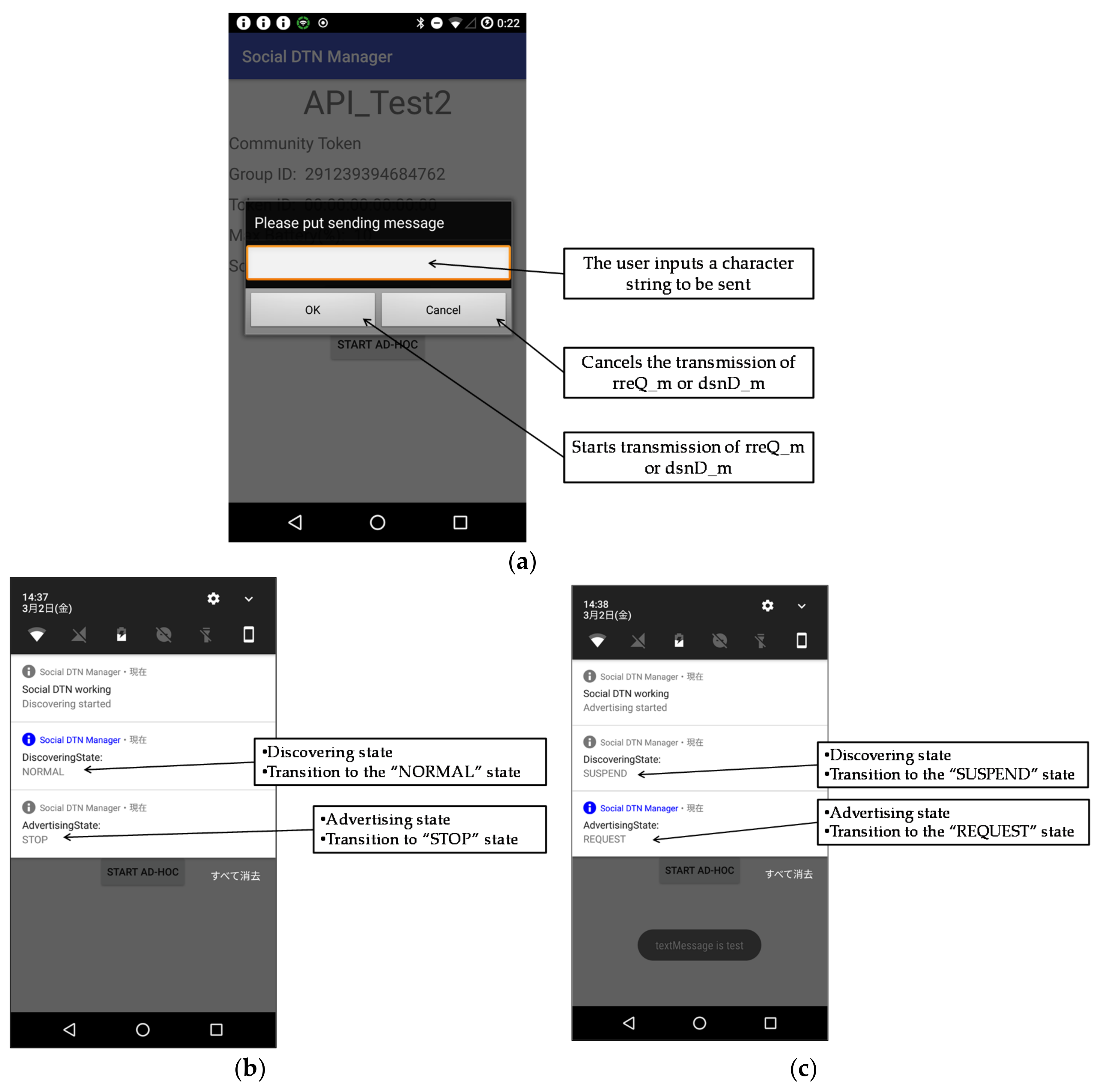
The user taps “Text” on the screen shown in Figure 7b. The user enters a character string on the screen in Figure 9a, and taps “OK.” If the routing table of the source node has no information about the destination node address, the source node suspends discovery operation and starts advertising operation. Thus, an rreQ_m is broadcast.
When a relay node starts the application and starts discovery operation, the screen shown in Figure 9b is displayed. When the relay node discovers the rreQ_m, it attempts to set up a connection to the terminal that has sent the rreQ_m. After this connection is set up, the relay node receives the rreQ_m and recognizes that it is a relay node. To forward the rreQ_m, the relay node starts advertising operation as shown in Figure 9c.
When the destination node starts the application and starts discovery operation (Figure 9b), it discovers the rreQ_m being broadcast, and attempts to set up a connection to the relay node. After this connection is set up, the destination node receives the rreQ_m, recognizes that it is the destination node, creates an rreP_m, and starts advertising operation (Figure 9c).
When the relay node discovers rreP_m (Figure 9b), it checks whether its routing table has information about the destination of that message. If it has, it establishes an ad hoc connection to the terminal that has sent the rreP_m. After that, it receives the rreP_m, recognizes that it is a relay node, and starts advertising operation to forward the rreP_m (Figure 9c).
When the source node receives the rreP_m, it sends to the destination node a dsnD_m that contains the text input by the user. We confirmed that the destination node successfully received that message.
5.2. Route Establishment Time
We measured the time it takes between the time when the source node transmits an rreQ_m and the time when it receives an rreP_m. The route establishment request time is defined as a period between the time when the source node starts advertising operation and the time when the destination node has received the message and confirms that the communication with the relay node has been discarded, as shown in Figure 5. The route establishment response time is defined as a period between the time when the destination node completes the creation of an rreP_m based on the rreQ_m it has received and the time when the source node has received the rreP_m and starts advertising operation to send data, as shown in Figure 5. These two types of time were calculated from stored log data.
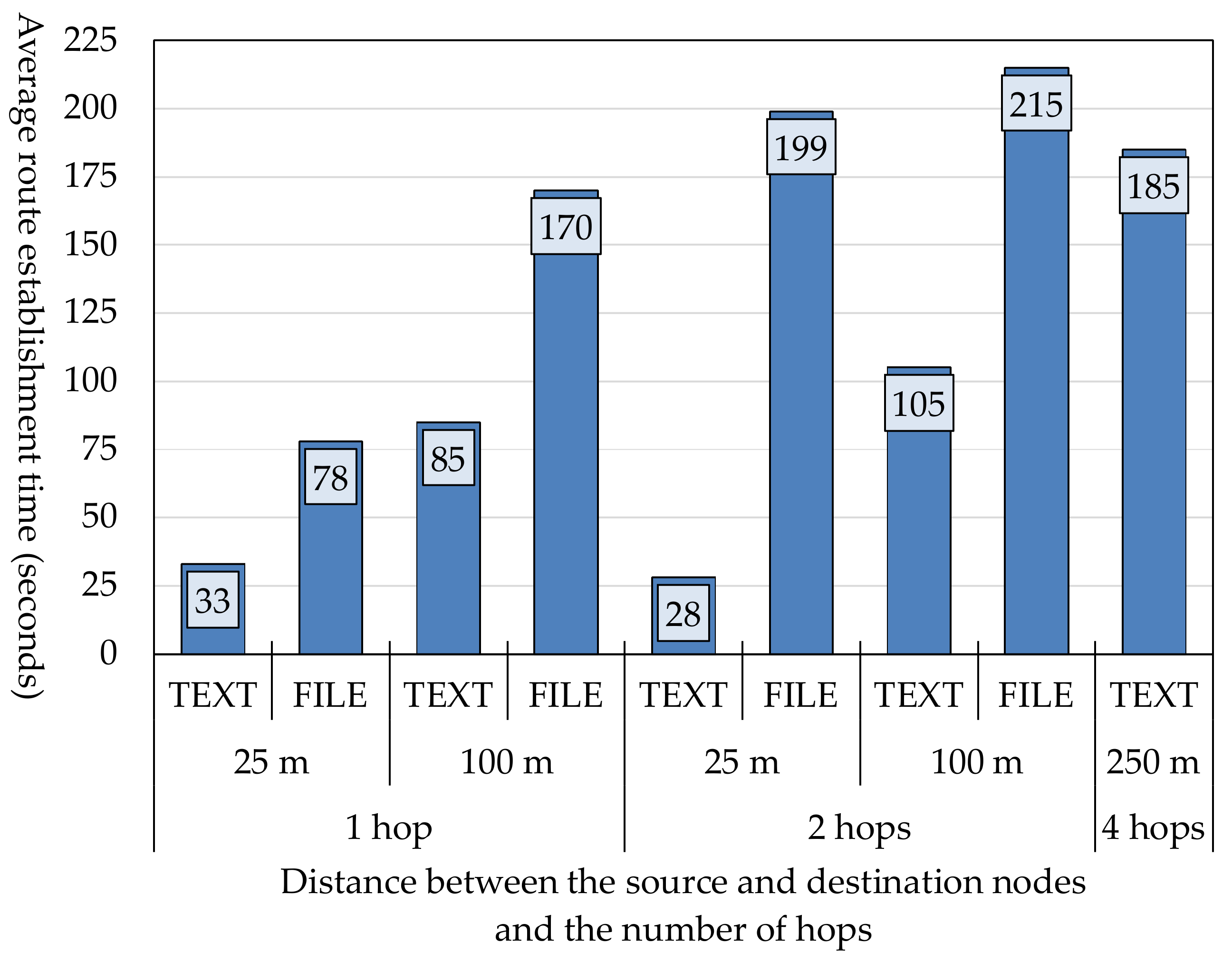
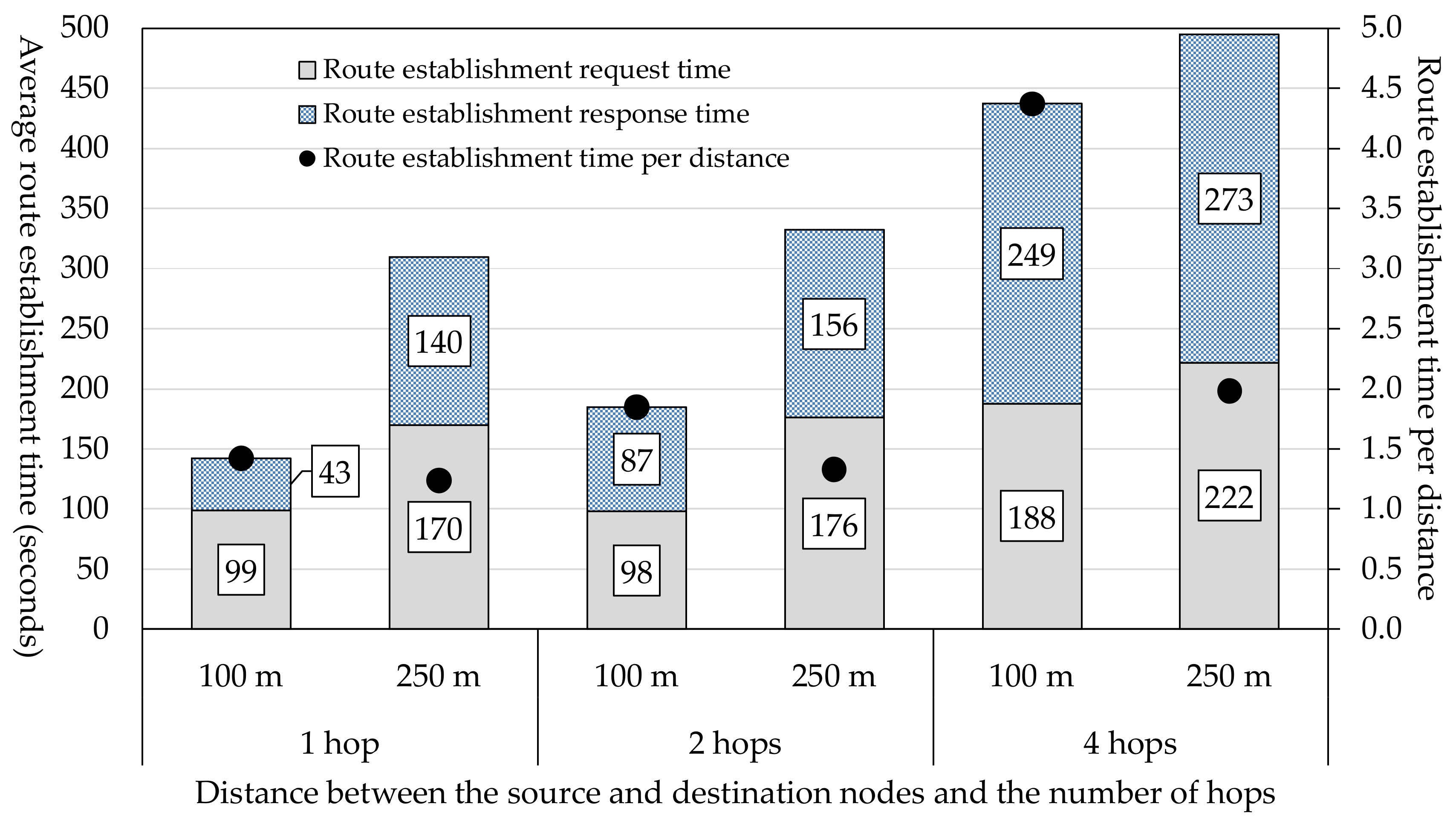
Using the terminals shown in Table 6 and the network structure shown in Figure 8, we measured the route establishment time three times for each of the three patterns (three different numbers of hops). Detailed experimental conditions are shown in Table 9. Relay nodes were located between the source node and the destination node. When a relay node received a message from the source node, the person who held the relay node began to walk. The average values of the measurements are shown in Figure 10.
In cases where the distance was 100 m, as the number of hops was increased from one to two, the average route establishment time increased moderately from 142 s to 185 s but when the number of hops was increased to four, the average route establishment time jumped to 437 s. In cases where the number of hops was two, the route establishment time for a distance of 100 m was much shorter than that for a distance of 250 m. However, in cases where the number of hops was four, the route establishment time for a distance of 250 m was 495 s, which was only slightly longer than the route establishment time for a distance of 100 m, which was 437 s. In spite of the fact that the difference in distance was 150 m, the difference in route establishment time was only 58 s. This difference was very small considering that it takes 108 s for a person to walk 150 m at a speed of 5 km/h. The route establishment time per distance for the case of 100 m was much longer than that for the case of 250 m. This indicates that, when there are many other terminals in an area within which a terminal can communicate with another terminal, the route establishment time increases.
More specifically, according to the specifications of Nearby Connections API [13], a communication is established when the Advertiser broadcasts a message and the Discoverer receives that message. If there are many Advertiser terminals, it takes a longer time for the Discoverer to receive messages. Specifically, even if a terminal sets up a connection with another terminal, it rejects reception of messages from this terminal if it finds that it does not have information about this terminal in its routing table. In other words, a terminal cannot decide whether to permit message exchange with another terminal until after it has set up a connection with that terminal. This means that, the more terminals there are in an area within which a terminal can communicate with other terminals, the more processing load it takes for the terminal to receive messages. This results in an increase in the time needed to establish a route.
In addition, Nearby Connections API [13] uses a cool time at the phase when a terminal sends communication link requests to other terminals. A Discoverer may discover an Advertiser that is not listed in its routing table and try to communicate with it. In such a case, communication is ultimately not established and discarded. However, according to the specifications of Nearby Connections API [13], the Discoverer must wait for a certain time (about 30 s) after this attempted communication was discarded before it can start discovery operation again. During this cool time, the Discoverer cannot discover other nodes. This is one of the reasons why it took a long time to establish a communication. As in the previous case, the more Discoverers there are in an area within which the Advertiser can communicate with another node, the more frequently this type of event occurs.
5.3. Route Establishment Time When There Are Terminals Belonging to Different Groups
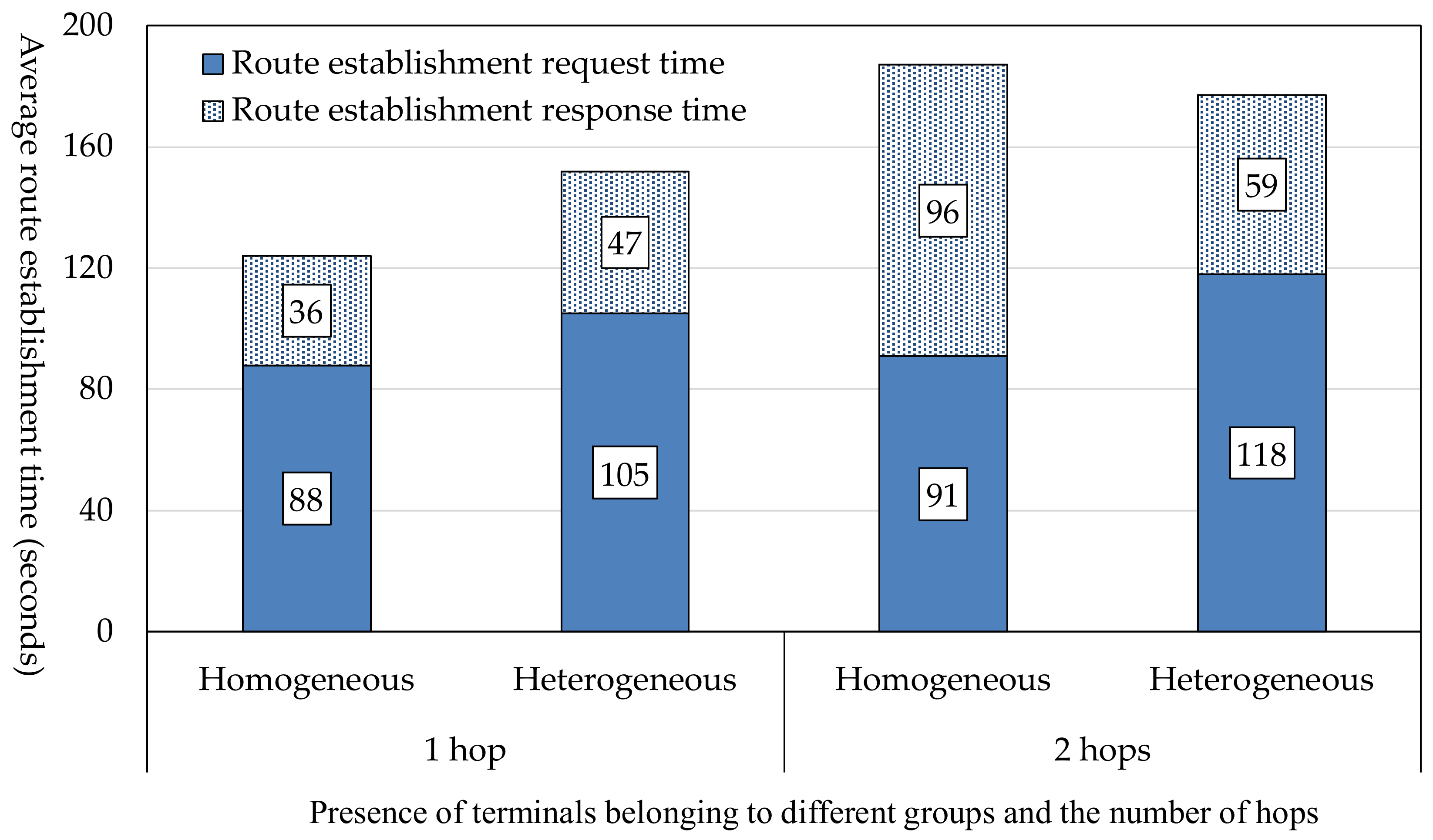
We made experiments to examine whether route establishment time changes if multiple terminals try to establish routes and if there are terminals nearby that have community tokens different from that of a particular terminal. The network structure used in this experiment is shown in Figure 11. The conditions for this experiment are shown in Table 10.
The results of the experiment are shown in Figure 12. In the case of one hop, the route establishment time was shorter when all terminals belonged to the same group (homogeneous). However, in the case of two hops, the route establishment time was shorter when there were terminals that belonged to different groups (heterogeneous). This is because the time needed to start communication varies because of the specifications of Nearby Connections API [13], as mentioned in Section 5.2. However, terminals belonging to another group hardly affected the route establishment time. The reason is that, in this system, a terminal decides whether to establish a communication with another terminal successively based on both community tokens and information in its routing table.
5.4. Data Exchange Time
We measured the time needed for a number of terminals to exchange information after they have established routes. The network structure used is the same as shown in Figure 8. The experimental conditions are shown in Table 11.
The results of the experiment are shown in Figure 13. The data exchange time is the time needed to execute everything in Figure 5b. It increases as the number of hops increases or the distance between the source node and the destination node increases. For the reason explained in Section 5.2, the data exchange time increases when there are many terminals in the area concerned. However, when an image file is to be sent, Nearby Connections API [13] automatically decides whether Bluetooth or Wi-Fi Direct is used. The user cannot make a selection. Therefore, we were not able to know which of the two was used.
6. Conclusions
The authors have developed an Android OS application that enables members of an SNS community to build a DTN by sharing a community token and to exchange messages. When the source node wants to establish a communication to the destination node in the DTN, they exchange control messages for route establishment. These messages are also used by relay nodes to create their routing tables. This can reduce flooding of message copies. The developed application is a social DTN manager that incorporates these functions and Facebook Graph API [12] and Nearby Connections API [13]. We have installed it in Android terminals and confirmed that a social DTN can successfully be built and that nodes can exchange data.
A problem with the above implementation was that the communication speed was not stable because of the restrictions imposed by the API specifications. To further improve the performance, it is necessary to devise a way to resolve hardware restrictions. It is also necessary to study the implementation of a function that enables the source node to access the Internet via the destination node that is connected to a Wi-Fi access point. Furthermore, it is necessary to verify updating of the token ID of a community token when the number of SNS group members change and the method of discriminating between new and old token IDs.
Author Contributions
Hidenori Takasuka and Koichi Hirai designed the proposed method, developed the software prototype of the evaluation system, collected the evaluation data and wrote the initial draft of the paper. Kazumasa Takami provided the direction for their research activities and refined the proposed method, the analysis of the evaluation results and the writing of the paper.
Conflicts of Interest
The authors declare no conflict of interest.
References
- Papadopoulou, E.; Gallacher, S.; Taylor, N.K.; Williams, M.H.; Blackmun, F.L.; Ibrahim, I.S.; Lim, M.I.; Mimtsoudis, I.; Skillen, P.; Whyte, S. Combining Pervasive Computing with Social Networking for a Student Environment. In Proceedings of the Twelfth Australasian Symposium on Parallel and Distributed Computing, Auckland, New Zealand, 20–23 January 2014; pp. 11–19. [Google Scholar]
- Hirai, K.; Takami, K. Building a Social MANET based on an SNS Community Token. In Proceedings of the 13th International Symposium on Frontiers of Information Systems and Network Applications (FINA-2017), Taipei, Taiwan, 27–29 March 2017. [Google Scholar]
- Tsuru, M.; Uchida, M.; Takine, T.; Nagata, A.; Matsuda, T.; Miwa, H.; Yamamura, S. Delay tolerant networking technology: The latest trends and prospects. IEICE Commun. Soc. Mag. 2011, 2011, 57–68. [Google Scholar] [CrossRef]
- Vahdat, A.; Becker, D. Epidemic Routing for Partially-Connected Ad Hoc Networks; Technical Report CS-2000-06; Duke University: Durham, NC, USA, 2000. [Google Scholar]
- Spyropoulos, T.; Psounis, K.; Raghavendra, C.S. Spray and Wait: An Efficient Routing Scheme for Intermittently Connected Mobile Networks. In Proceedings of the ACM SIGCOMM’05 Workshops, Philadelphia, PA, USA, 22–26 August 2005. [Google Scholar]
- LeBrun, J.; Chuah, C.; Ghosal, D.; Zhang, M. Knowledge-Based Opportunistic Forwarding in Vehicular Wireless Ad Hoc Networks. In Proceedings of the IEEE Vehicular Technology Conference (VTC 2005-Spring), Stockholm, Sweden, 30 May–1 June 2005. [Google Scholar]
- Zhao, W.; Ammar, M.; Zegura, E. A Message Ferrying Approach. In Proceedings of the 5th ACM International Symposium on Mobile Ad Hoc Networking and Computing (MobiHoc’04), Tokyo, Japan, 24–26 May 2004; pp. 187–198. [Google Scholar]
- Okamoto, K.; Takami, K. Routing Based on Information about the Routes of Fixed-Route Traveling Nodes and on Destination Areas Aimed at Reducing the Load on the DTN. Future Internet 2016, 8, 15. [Google Scholar] [CrossRef]
- Ippisch, A.; Graffi, K. Infrastructure Mode Based Opportunistic Networks on Android Devices. In Proceedings of the IEEE 31st International Conference on Advanced Information Networking and Applications (AINA 2017), Taipei, Taiwan, 27–29 March 2017. [Google Scholar]
- Ippisch, A.; Sati, S.; Graffi, K. Device to device communication in mobile Delay Tolerant networks. In Proceedings of the 21st International Symposium on Distributed Simulation and Real Time Applications (DS-RT), Rome, Italy, 18–20 October 2017; pp. 91–98. [Google Scholar]
- Lindgren, A.; Doria, A.; Schel’en, O. Probabilistic Routing in Intermittently Connected Networks. ACM SIGMOBILE Mobile Comput. Commun. Rev. 2003, 7, 19–20. [Google Scholar] [CrossRef]
- Facebook for Developers. Available online: https://developers.facebook.com/docs/graph-api/overview/ (accessed on 6 January 2018).
- Google Developers. Available online: https://developers.google.com/nearby/connections/overview (accessed on 6 January 2018).
- Boldrini, C.; Conti, M.; Jacopini, J.; Passarella, A. HiBOp: A History Based Routing Protocol for Opportunistic Networks. In Proceedings of the IEEE International Symposium on World of Wireless, Mobile and Multimedia Networks (WoWMoM’07), Helsinki, Finland, 18–21 June 2007; pp. 1–12. [Google Scholar]
- Cyanogenmod. Available online: http://web.archive.org/web/20160410142436 (accessed on 26 February 2018).
- Thinktube Inc. Available online: http://www.thinktube.com/android-tech/46-android-wifi-ibss (accessed on 26 February 2018).
- Debian Kit for Android. Available online: http://sven-ola.commando.de/repo/debian-kit-en.html (accessed on 26 February 2018).
- RFC 3651—Ad Hoc On-Demand Distance Vector (AODV) Routing. Available online: https://www.ietf.org/rfc/rfc3561.txt (accessed on 21 March 2018).
- Android Studio, SDK Platform Tools Release Notes. Available online: https://developer.android.com/studio/releases/platform-tools.html (accessed on 4 March 2018).
- Facebook Android SDK. Available online: https://developers.facebook.com/docs/android?locale=en_US (accessed on 4 March 2018).
- Google Play Service API (Nearby). Available online: https://developers.google.com/android/guides/setup (accessed on 4 March 2018).
- Github Google-Gson. Available online: https://github.com/google/gson (accessed on 4 March 2018).
Figure 1.
Example of using a social DTN (delay, disruption, disconnection tolerant networking). (a) The left figure shows an environment, such as an airport, where the user (e.g., a visitor from abroad) can access the Internet; (b) The right figure shows an environment, such as on the street, where the user cannot access the Internet.

Figure 2.
Proposed DTN architecture.

Figure 3.
Sequences for group information acquisition and community token sharing. (a) Group information acquisition; (b) Community token sharing.
Figure 3.
Sequences for group information acquisition and community token sharing. (a) Group information acquisition; (b) Community token sharing.
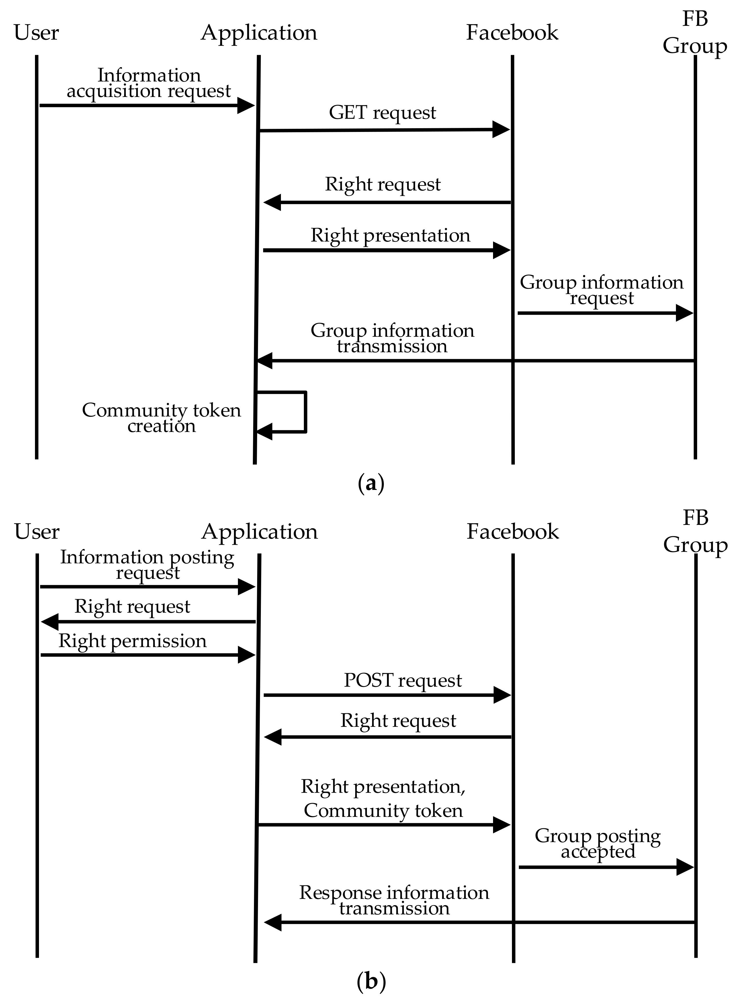
Figure 4.
Analysis tree to decide whether to accept the received message.
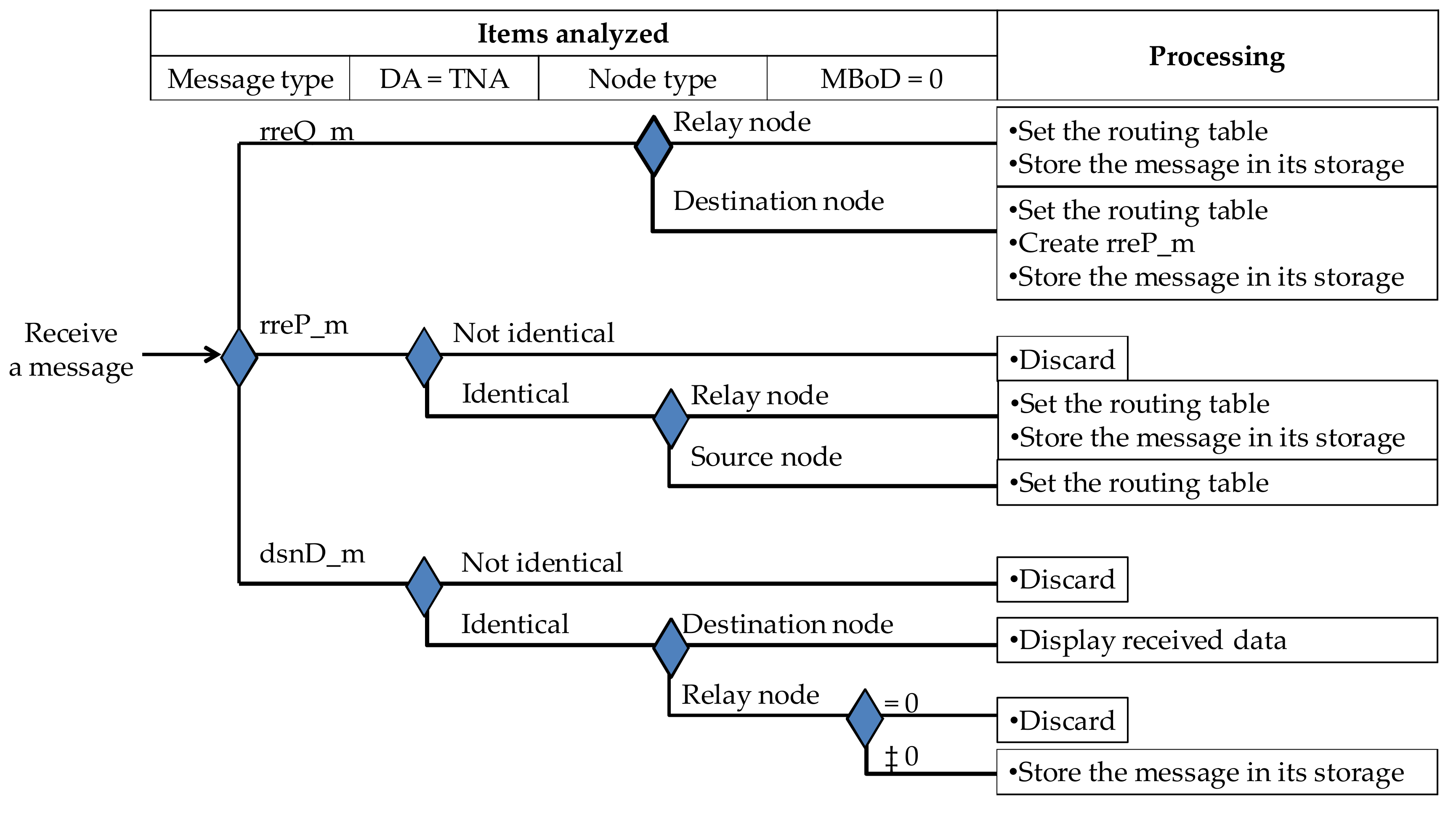
Figure 5.
Sequence of message exchange for DTN communication. (a) Route establishment; (b) Data exchange.
Figure 5.
Sequence of message exchange for DTN communication. (a) Route establishment; (b) Data exchange.

Figure 6.
Configuration of the experimental system.

Figure 7.
Graphical user interface (GUI) examples of the social DTN manager application developed. (a) GUI layout for linkage to Facebook after a community token has been created; (b) Message type selection dialog for sending text or files.
Figure 7.
Graphical user interface (GUI) examples of the social DTN manager application developed. (a) GUI layout for linkage to Facebook after a community token has been created; (b) Message type selection dialog for sending text or files.

Figure 8.
Structure of the experimental network.
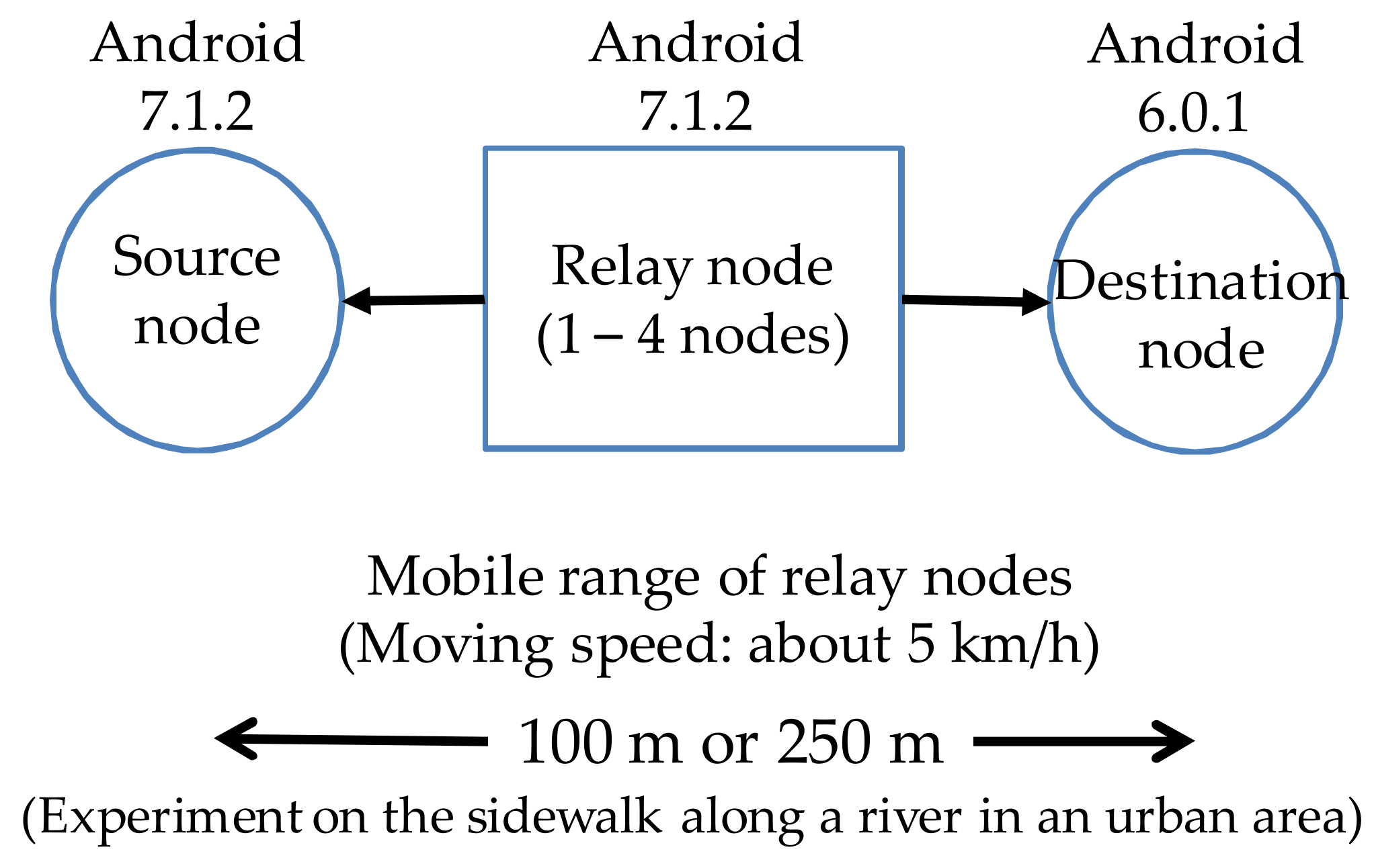
Figure 9.
Text data transmission screen. (a) Text input screen; (b) Screen when discovery operation has been started; (c) Screen when advertising operation has been started.
Figure 9.
Text data transmission screen. (a) Text input screen; (b) Screen when discovery operation has been started; (c) Screen when advertising operation has been started.

Figure 10.
Required route establishment time.

Figure 11.
Network structure used in the experiment for a case where terminals belonging to different groups exist.
Figure 11.
Network structure used in the experiment for a case where terminals belonging to different groups exist.

Figure 12.
Route establishment time when there are terminals belonging to different groups.

Figure 13.
Data exchange time.

Table 1.
Classification of routing methods according to the criteria used to determine flooding and according to routing table creation methods.
Table 1.
Classification of routing methods according to the criteria used to determine flooding and according to routing table creation methods.
| Community Identification | Routing Table | Routing Table Creation | Criteria Used to Determine Flooding | Routing Method | |
|---|---|---|---|---|---|
| None | None | None: flooding of messages to all adjacent nodes | Epidemic [4] | ||
| Flooding of messages to nodes up to a certain number of hops (a certain number of copies) | Spray and Wait [5] | ||||
| Distance to the destination node | Location-based [6] | ||||
| Motion vector to the destination node | motion vector scheme (MoVe) [6] | ||||
| Used | Proactive | Fixed | Routing table (includes encounter probability calculation type, social-context-awareness type) | Message ferry [7], Routing based on traveling route information [8] | |
| Encounter information sharing | Meta information exchange [9,10], PRoPHET [11], HiBOp [14] | ||||
| Present | Reactive | Proposed method | |||
Table 2.
Methods of building an ad hoc network with Android terminals.
| Implementation | Detailed Method | Usage Conditions | Position |
|---|---|---|---|
| OS modification | Custom operating system (OS) + patches [15,16] |
| Existing methods |
| Building a virtual environment called “Debian” [17] | |||
| Application | Google Nearby Connections API [13], which is independent of OS |
| Proposed method |
Table 3.
Contents of a community token.
| Name | Overview | Usage |
|---|---|---|
| Group ID | The ID used in the social networking service (SNS) is used. | This is used to identify a group. |
| Token ID | The initial value is the MAC (Media Access Control) address of the source node. The value is incremented by one each time the community token is updated. | This is used to determine which community token is new. |
| Max-Battery of Device (MBoD) | This is the maximum level of battery power consumption in communication. This is reduced by the level of battery power consumed during the DTN communication. | If the value of a node becomes “0”, the node is eliminated from routing in order to avoid excessive use of resources. |
| Source node address | This is the MAC address of the source node that has created the community token. | This is used for routing. (See Section 3.4 for detail). |
Table 4.
Message types and elements route establishment request (rreQ_m); route establishment response (rreP_m); data messages (dsnD_m).
Table 4.
Message types and elements route establishment request (rreQ_m); route establishment response (rreP_m); data messages (dsnD_m).
| Type | rreQ_m | rreP_m | dsnD_m | |
|---|---|---|---|---|
| Element | ||||
| Message type m_type (1 byte) | Yes | Yes | Yes | |
| Route establishment request ID (8 bytes) | Yes | Yes | Yes | |
| Destination node address DA (17 bytes) | Yes | Yes | Yes | |
| Source node address SA (17 bytes) | Yes | Yes | Yes | |
| Transmitted data (n bytes) | No | No | Yes | |
Table 5.
Structure of a routing table.
| Element | Remarks |
|---|---|
| Terminal node address (TNA) | DA and SA, which are elements in each message |
| Relay node address (RNA) | The address of the adjacent node that has received rreQ_m or rreP_m that contains TNA. The SA of that message is set in TNA. The address of the adjacent node is set in RNA. |
Table 6.
Main functions implemented.
| Function Name | Program Size | Functional Overview |
|---|---|---|
| Linkage with Facebook | 853 lines | Enables the user to use his/her own Facebook account to browse, post or delete messages in the group he/she belongs to as the administrator. |
| Terminal information acquisition | 191 lines | Obtains the terminal’s MAC address and MBoD. |
| Community token management | 639 lines | Uploads or downloads a community token created using terminal information to or from the Facebook group. |
| DTN routing | 2087 lines | Establishes an ad hoc communication link and performs routing. |
| Text and file exchange | 244 lines | Exchanges text and files with terminals to which a communication link has been established. |
Table 7.
Development environment and application execution conditions.
| Classification | Item | Contents |
|---|---|---|
| Development environment | Machine | DELL OptiPlex 3040 |
| OS | Windows10 Pro | |
| Application development software | Android Studio 3.0 (Gradle version 4.1) | |
| Build tool | API 26.0.2: Android8.0 (Oreo) [19] | |
| Application execution conditions | Application name | Social DTN Manager |
| Operating environment | Android sdk 15 (Android 4.3) or higher | |
| Application type | Android SDK, Java | |
| Third-party plug-ins | Facebook Android SDK [20] Google Play Service API (nearby) [21] Google gson [22] |
Table 8.
Specifications of the terminals used in the experiment.
| Terminal Model | OS Version | Usage |
|---|---|---|
| Nexus5 | Android 7.1.2 | Source node |
| HUAWEI Y6 SCL-L02 IMEI:861105030008770 | Android 7.1.2 | Relay node |
| HUAWEI Y6 SCL-L02 IMEI: 861105030097666 | Android 7.1.2 | Relay node |
| BLUEDOT BNP-500 Serial: ZLY5CUNNQS6HUWK7 | Android 4.4.2 | Relay node |
| BLUEDOT BNP-500 Serial: OVTSEY79QO4HZT8D | Android 4.4.2 | Relay node |
| NEC PC-TE507FAW | Android 6.0.1 | Destination node |
Table 9.
Experimental conditions for the measurement of the route establishment time.
| Item | Value |
|---|---|
| Number of terminals | 3, 4 or 6 |
| Number of hops (i.e., number of relay nodes) | 1, 2 or 4 |
| Number of experiments | 3 experiments per pattern |
| Use of different community tokens | None |
Table 10.
Experimental conditions for a case where terminals belonging to different groups exist.
| Item | Value |
|---|---|
| Number of terminals | 5 or 6 |
| Number of hops | 1 or 2 |
| Number of experiments | 2 per pattern |
| Number of terminals belonging to a different group | 1 advertising terminal and 1 discovering terminal |
| Number of different types of community token | 3 |
Table 11.
Experimental conditions for measuring data exchange time.
| Item | Value |
|---|---|
| Number of terminals | 3, 4 or 6 |
| Number of hops | 1, 2 or 4 |
| Number of experiments | 3 per pattern |
| Distance between the source node and the destination node | 25 or 100 m (250 m only in the case of 4 hops) |
| Exchanged data | Character string (TEXT = 55 bytes), Image file (FILE = 1 Mbytes) |
| Presence of different community tokens | None |
© 2018 by the authors. Licensee MDPI, Basel, Switzerland. This article is an open access article distributed under the terms and conditions of the Creative Commons Attribution (CC BY) license (http://creativecommons.org/licenses/by/4.0/).
Share and Cite
MDPI and ACS Style
Takasuka, H.; Hirai, K.; Takami, K. Development of a Social DTN for Message Communication between SNS Group Members. Future Internet 2018, 10, 32. https://doi.org/10.3390/fi10040032
AMA Style
Takasuka H, Hirai K, Takami K. Development of a Social DTN for Message Communication between SNS Group Members. Future Internet. 2018; 10(4):32. https://doi.org/10.3390/fi10040032
Chicago/Turabian StyleTakasuka, Hidenori, Koichi Hirai, and Kazumasa Takami. 2018. "Development of a Social DTN for Message Communication between SNS Group Members" Future Internet 10, no. 4: 32. https://doi.org/10.3390/fi10040032
Note that from the first issue of 2016, this journal uses article numbers instead of page numbers. See further details here.